

Page 1
NCB LINE
HORIZONTAL CLOSED COUPLED
CENTRIFUGAL PUMPS
INSTALLATION, USE AND MAINTEINANCE MANUAL
Page 2

CONTENTS
1. general ................................................................................................................. 3
1.1. guarantee ..................................................................................................... 3
1.2. testing .......................................................................................................... 3
1.3. rating plate ................................................................................................... 3
2. description ............................................................................................................ 4
2.1. construction .................................................................................................. 4
2.2. shaft sealing stuffing box ................................................................................ 4
2.3. shaft sealing – mechanical seals....................................................................... 6
2.3.1. single unbalanced mechanical seal ................................................................ 6
2.3.2. Single mechanical seal with quench ............................................................... 7
2.3.3. External mechanical seal .............................................................................. 7
2.4. double mechanical seal ................................................................................... 8
2.4.1. Double tandem Mechanical seal .................................................................... 8
3. erection of the pump ............................................................................................. 9
3.1. INSTALLATION ............................................................................................... 9
3.2. Control ......................................................................................................... 9
3.3. piping ......................................................................................................... 10
4. operation of the pump ........................................................................................ 11
4.1. Starting up .................................................................................................. 11
4.2. Shutdown .................................................................................................... 11
4.3. Supervision and maintenance ........................................................................ 11
4.4. Operating troubles and their possible causes ................................................... 11
5. Inspection and Renewal of Wear Parts ............................................................... 13
5.1. General ....................................................................................................... 13
5.2. Dismantling the Pump ................................................................................... 13
5.3. Reassembly of the Pump ............................................................................... 14
APPENDIX A – SECTIONAL DRAWING – standard execution ..................................... 15
APPENDIX E – RECOMMENDED SPARE PARTS ........................................................... 17
APPENDIX F – ALLOWABLE FORCES AND MOMENTS ................................................. 18
Page 3
SAFETY NOTICE
Before starting the pump carry out the following operations
Install and operate the pump according to the instruction indicated
in this manual
Make sure that the pump lay on a stable foundation and that the
alignment between pump and motor is correct before and after
fixing baseplate and piping
Fill the bearing house with the reccomended oil
Make sure that the coupling guard is correctly and safetely installed
Make sure that all the external connections to the pump and to the
shaft seal are connected properly
Never operate the pump when dry
Page 4
1. GENERAL
3
TYPE
SERIAL No.
ITEM
RPM kW
H [m]
YEAR
1. GENERAL
1.1. GUARANTEE
We undertake to guarantee the construction materials only if the pump is operated
according to the conditions of service given in our order confirmation.
The operating and maintenance personnel should study these operating instructions
before erecting the pump.
In accordance with our terms of delivery we cannot accept responsibility for damages
resulting from the failure to follow these instructions.
1.2. TESTING
Before leaving our works all pumps are subjected to performance test. Only pumps in
perfect working order which meet the design performance figures leave our works. By
observing the following instructions the pump will give trouble-free operation and meet
the specified design performance.
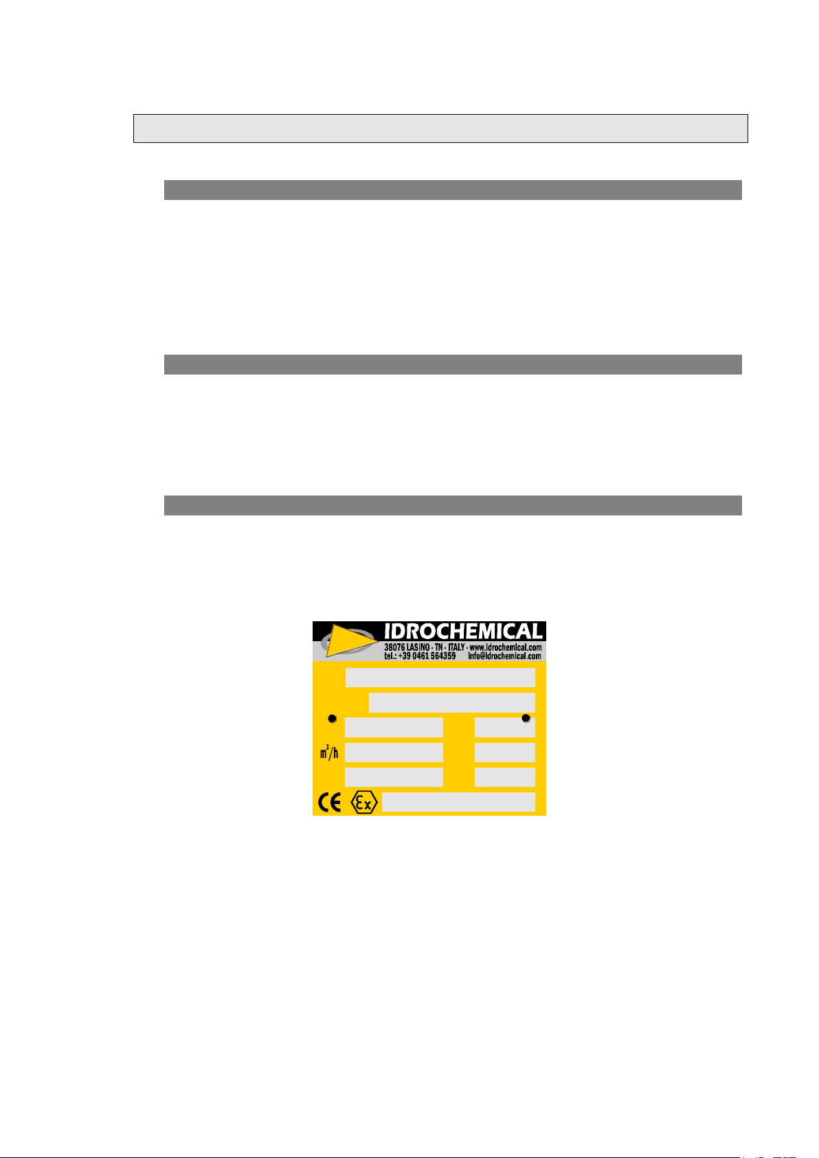
1.3. RATING PLATE
The work and item numbers are stamped on the rating plate. When ordering spare parts,
you are required to provide these numbers as well the exact description of the part and
its number as listed in the component list.
Figure 1 Rating Plate
Page 5
2. DESCRIPTION
4
2. DESCRIPTION
2.1. CONSTRUCTION
The NCB chemical pump is a single stage volute casing pump of process form
construction with axial suction and radial discharge nozzles. The one piece volute casing,
opening onto the discharge side, which has sturdy integrally cast feet, can remain
attached to the piping during maintenance work.
With pump ends conforming to ISO 2858 dimensional and technical standards and to ISO
5199 design criteria, the NCB provides a compact, space-saving arrangement ideal for
industrial processes or installations when space is at a premium. NCB pumps are fitted
with standard, readily available electric motors so the user can choose an enclosure to
suit the application.
The axial thrust is hydraulically balanced by means of back vanes on the impeller. The
back vanes are left or trimmed according to suction pressure, so that the pressure on the
stuffing box/mechanical seal can be balanced.
The clearance between the impeller and wear ring is determined by the temperature of
the fluid and the construction materials.
The impeller is located on the shaft by means of parallel key and retained by a cap nut.
If the pump handles a corrosive liquid, to prevent the medium coming into contact with
the shaft, sealing rings of suitable material are fitted between the impeller nut, impeller,
shaft sleeve and flinger ring.
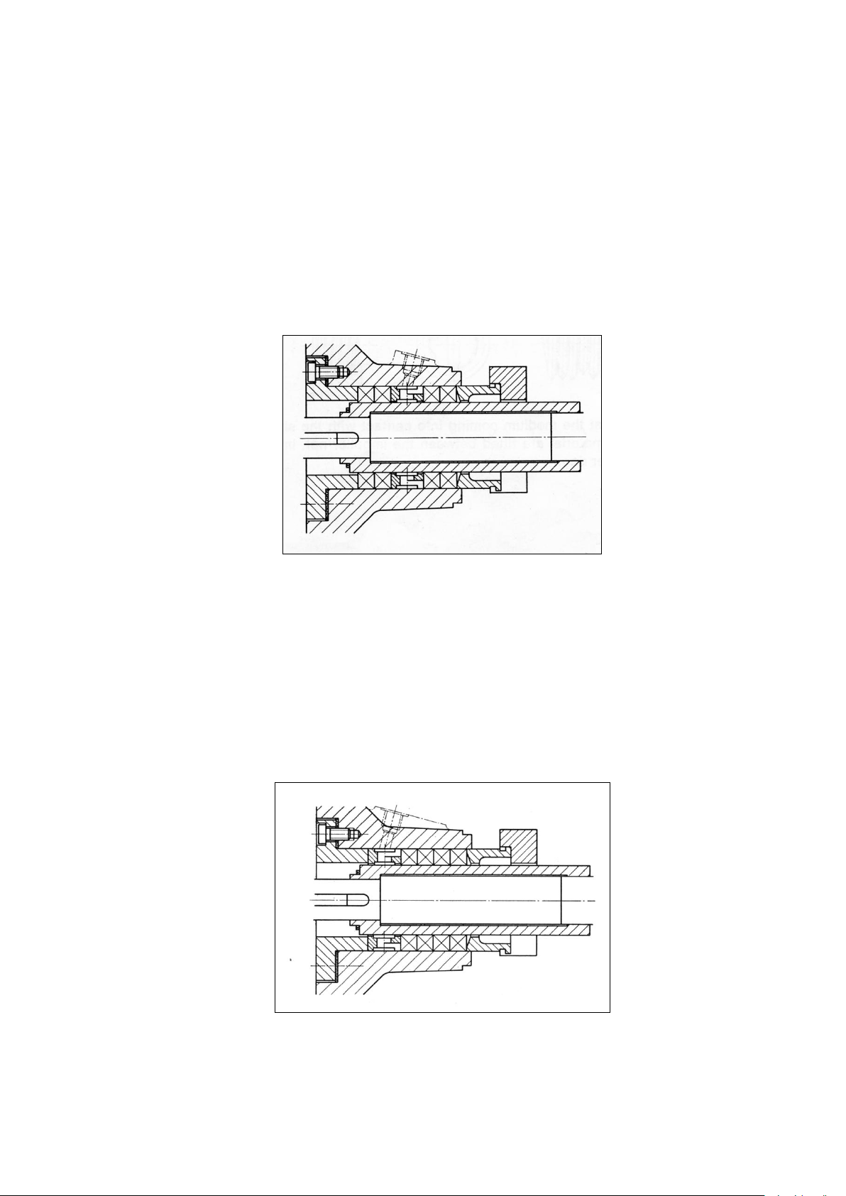
2.2. SHAFT SEALING STUFFING BOX
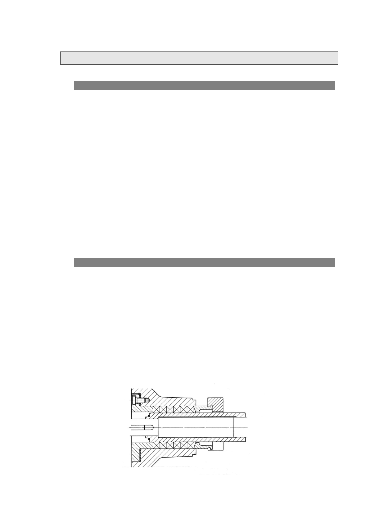
The pump shaft is sealed at the casing back plate by soft stuffing box packing. The
stuffing box is normally packed with 4 packing rings and a lantern ring, or 6 packing
rings if the lantern is not required.
To repack the stuffing box the lantern ring, gland ring and gland can be removed as the
gland is open at the bottom and the lantern and gland rings are split.
Fluid is fed to the lantern ring when:
The packing must be cooled or lubricated
The packing must be flushed because the medium contains solids which can
damage the packing
The medium is toxic or pungent so that it does not leak out to the atmosphere
The medium evaporates at atmospheric pressure
Arrangement a) stuffing box without lantern ring
Page 6
2. DESCRIPTION
5
Figure 2 Arrangement a) stuffing box without lantern ring
The medium should be clean and free from impurities and have a good lubricating
properties and a moderate temperature.
The suction pressure must be somewhat greater than the atmospheric pressure so that
small quantities of the medium are forced out through the stuffing box packing to ensure
that the gland is adequately lubricated.
Arrangement b) Stuffing box with lantern ring between 4 packing rings
Figure 3 Arrangement b) Stuffing box with lantern ring between 4 packing rings
For fluids with poor lubricating qualities and a high temperature but clean and free from
abrasive impurities.
The suction pressure must be less than atmospheric pressure and the sealing fluid must
be fed in at a pressure of 1-2 atmospheres greater than the suction pressure. As small
quantities can penetrate into the pump, the sealing fluid must be compatible with the
pumped fluid.
Arrangement c) Stuffing box with lantern ring at bottom end of stuffing box
Figure 4 Arrangement c) Stuffing box with lantern ring at bottom end of stuffing
box
Page 7
2. DESCRIPTION
6
12
P
PP
ai
seal
body
grain
flushing
stationary
gasket
stationary
ring
pin
rotating
ring
rotating
gasket
spring(s)
This arrangement is recommended for fluids with high temperatures that contain
abrasive solids or tend to crystallize
2.3. SHAFT SEALING – MECHANICAL SEALS
The advantage of a mechanical seal over a stuffing box is that the seal face which is
subjected to wear, is at right angles to the surface of the shaft. Sealing takes place in the
radial gap between finely lapped stationary and rotating faces which are forced together
by a spring. While the pump is in operation the mechanical seal requires no servicing and
seals so that no leakage occurs.
In a short time a film of fluid penetrates between the seals faces which removes the
frictional heat by its circulatory effect. The circulating fluid depends on the liquid
pumped. It can be the liquid pumped provided it is clean or a compatible fluid introduced
from an external source.
The choice of seal depends on the conditions of service.
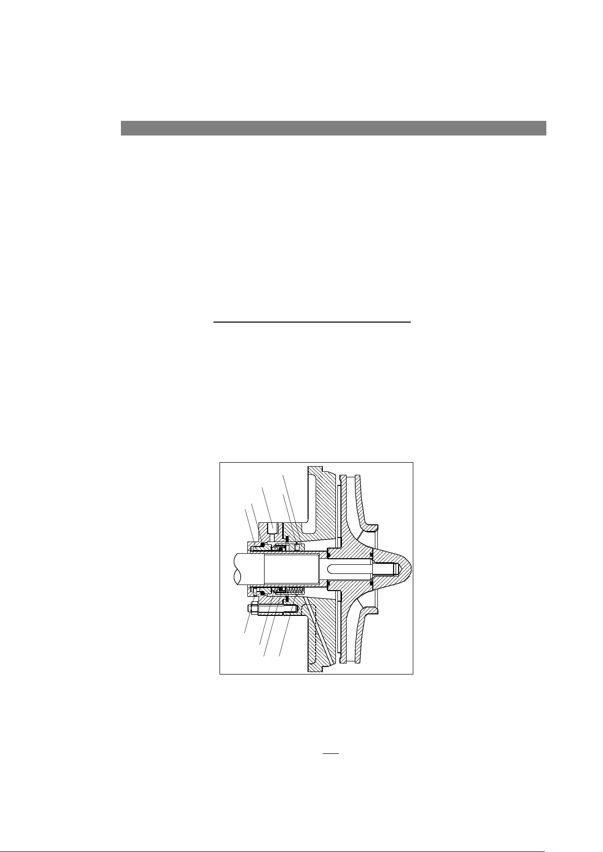
2.3.1. single unbalanced mechanical seal
This seal can only be employed when the fluid pumped is free from solids and does not
crystallise. The maximum permissible stuffing box pressure varies depending on the seal
manufacture. The circulating fluid is introduced at the seal faces by means of a
recirculation harness from the discharge nozzle to the sealing cover plate and drawn back
into the suction side of the pump by means of the impeller back vanes. The required flow
of the recirculating fluid depends on the fluid pumped and its temperature and can be
regulated by an orifice or a valve in such a way that the temperature at the sealing cover
plate is not appreciably higher than elsewhere in the pump.
Figure 5 Single unbalanced mechanical seal
The flushing liquid inlet pressure is generally given by the following equation:
Page 8
2. DESCRIPTION
7
sal body
grain
flushing
stationary
gasket
rotating
ring
rotating
gasket
spring(s)
stationary
ring
quench
inlet
lipseal
seal
body
grain
flushing
stationary
ring
rotating
ring
rotating
gasket
spring(s)
where Pi is the inlet pressure in bar, Pa the maximum pump suction pressure in bar and
ΔP the pump head in bar.
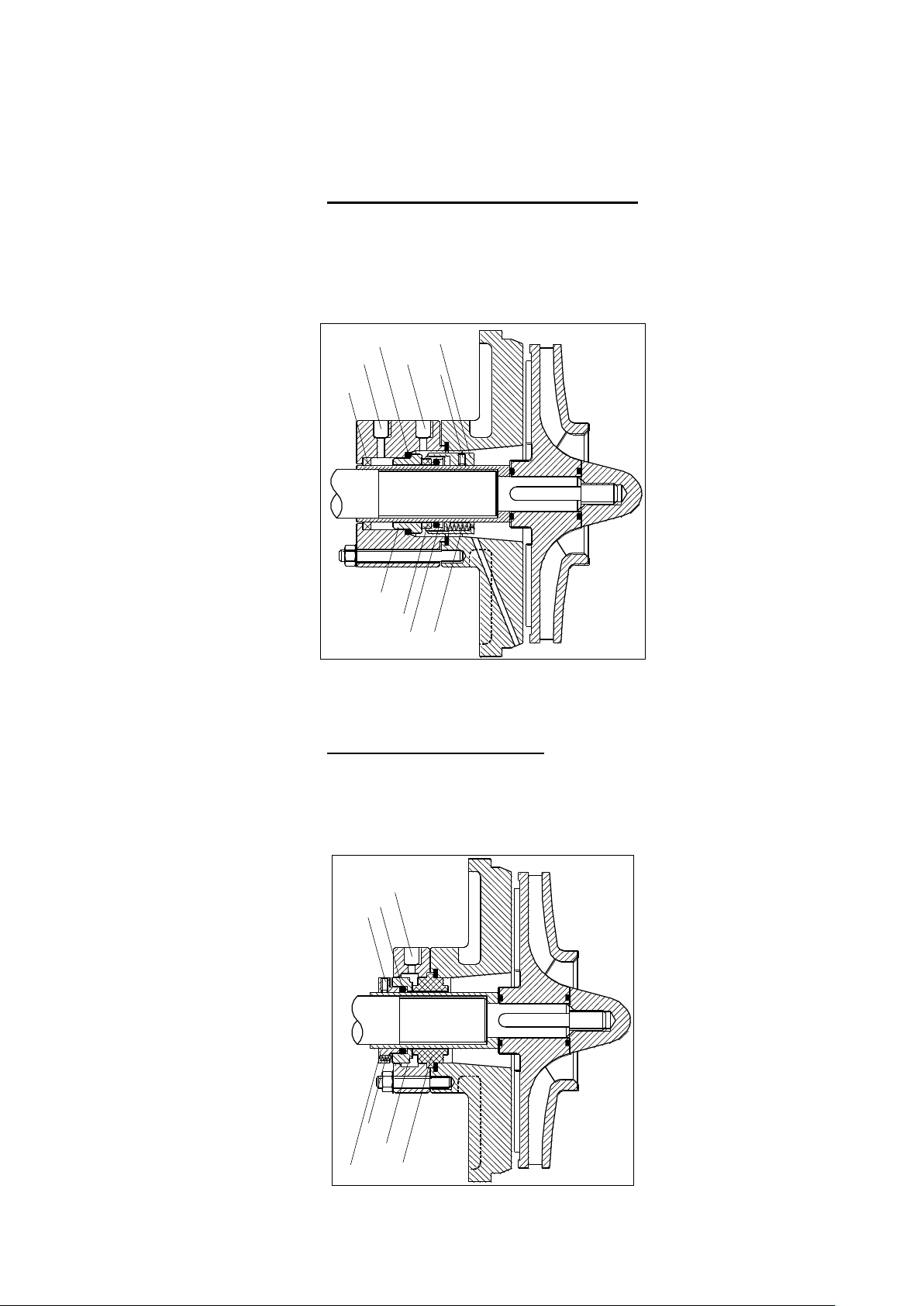
2.3.2. Single mechanical seal with quench
The quench is recommendable when medium forms solid deposits or crystalizes when it
comes in contact with the atmosphere or low temperature. Quench is normally applied
conveying steam or clean liquid at a pressure not exceeding 1 bar. Quench is helpful to
recover occasional leakages, or, in case of under vacuum, to avoid dry- running.
Figure 6 Quench
2.3.3. External mechanical seal
The media is inside the seal. The outer seal is generally used to handle corrosive or toxic
liquids. Springs and all the metallic parts are not in contact with the pumped fluid.
Page 9
2. DESCRIPTION
8
seal
body
grain
flushing
outlet
stationary
gasket
stationary
ring
pin
rotating
ring
rotating
gasket
spring(s)
seal
body
grain
flushing
inlet
spring(s)
stationary
ring
rotating
gasket
rotating
ring
seal
body
grain
flushing
stationary
gasket
stationary
ring
pin
rotating
ring
rotating
gasket
spring(s)
Seal
Body
grain
flushing
stationary
gasket
rotating
ring
rotating
gasket
spring(s)
stationary
ring
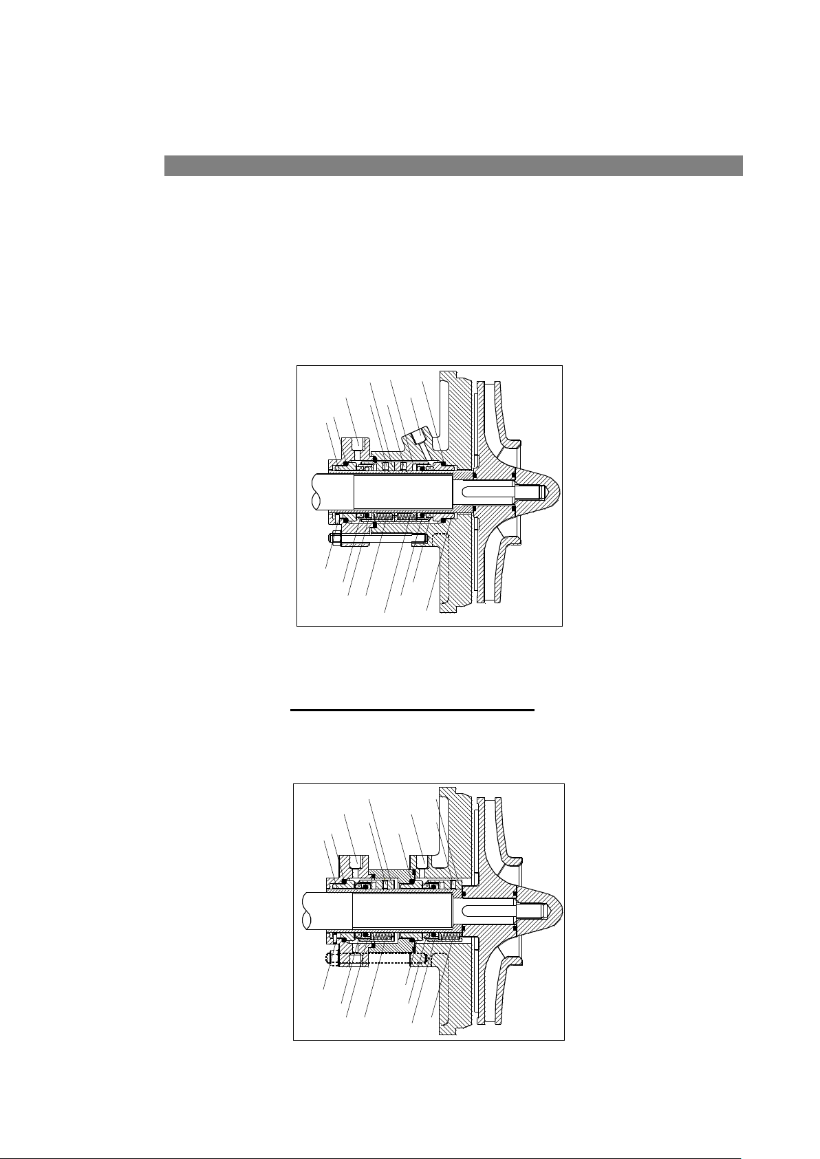
Figure 7 External mechanical seal
2.4. DOUBLE MECHANICAL SEAL
This arrangement is employed when the liquid contains solids, gels or crystallises when
cooled, is toxic or is near saturation and the danger of evaporation exists.
A compatible sealing fluid must be chosen as small quantities penetrate into the pump.
The sealing fluid is externally introduced into the seal housing through the casing
backplate and emerges through a connection in the sealing cover plate. The pressure of
the sealing fluid must be 1—2 bars above the internal pressure at the in-board seal face
but should not exceed a certain given design pressure. The flow of the sealing fluid can
be regulated by an orifice or a valve in such a way that the temperature at the sealing
cover plate is not appreciably higher than elsewhere in the pump.
Figure 8 Double mechanical seal (back to back)
2.4.1. Double tandem Mechanical seal
The inner seal works like a single seal while the secondary seal is set up for safety to
prevent leakages induced from a damage of the principal one.
Figure 9 Double tandem mechanical seal
Page 10
3. Erection of the pump
9
3. ERECTION OF THE PUMP
3.1. INSTALLATION
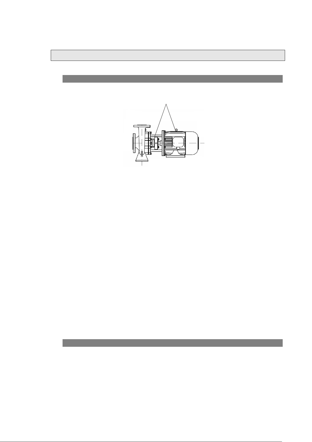
Lift and transport the pump-motor units, as indicated in figure 10
Figure 10
The suction pipe, whose internal diameter should never be smaller than the suction port,
should be arranged in accordance with the suction conditions and consider product and
temperature’s characteristics. Make sure that connections in the suction pipe are
perfectly airtight. Moreover, the suction pipe, in the horizontal sections must have a
positive slope towards the pump to avoid that air pockets occur inside the pipeline.
Should the pump run with a positive slope, pipe is descendant towards the pump. Should
the pump run with a negative slope in the suction pump, install a foot valve at the end of
the pipe, to allow and keep priming of the pump. Fit a check-valve in the delivery pipe to
protect the pump from too high counterpressures or reverse rotation (after each stop).
Suction and delivery pipes have to be supported aside from the pump but as close to it
as possible. Be sure that the pipes are installed to allow the perfect mating of flanges and
counterflanges, avoiding stress transmission to the pump. A compensation bellows is also
necessary to absorb expansions caused by hot liquids.
Electrical connection must be carried out by a qualified electrician in accordance with
local regulation. Make sure that the supply voltage corresponds to the voltage on the
motor plate. It will be the local responsible’ s task to make sure earthing is carried out
first and all the installation operations are performed in compliance with the applicable
regulation. Provide a device to disconnect each phase from the supply with a break of
3mm between the contacts in the open position. Regarding motor protection, install a
switch or a thermal relay for the current indicated on the motor plate, plus 5%.
3.2. CONTROL
After the pump has been erected the pump and driver should be examined to see if they
are standing true. A quiet running coupling prevents premature wear on the bearings.
The complete set should be easily turned by hand at the coupling.
The direction of rotation of the driver must be the same as that of the pump —see arrow
on the bearing house or casing. To check this the uncoupled motor should be switched on
for a short period.
The direction of rotation can be altered by changing the poles of two phases.
Page 11

3. Erection of the pump
10
2
3
1
36001mAh
m
Q
s
m
v
For a constant and efficient check, install a gauge on the discharge pipe and a vacuum
gauge on the suction pipe.
3.3. PIPING
The bore of the piping should not be smaller than the respective pump nozzles and free
from scale, welding beads and other foreign bodies. The piping should be so laid that it
transmits no stress to the flanges and nozzles when connected.
The piping bore at the discharge side should be so sized that a flow velocity not greater
than 2,5—3,0 m/sec. results so as to minimize friction loss in the piping. A control valve
should be incorporated into the discharge line as close to the pump discharge nozzle as
possible so that the flow and head can be regulated. Sharp bends, abrupt cross-sections
etc. should be avoided.
The suction line should be so arranged that air locks cannot form.
Eccentric reducers should be used to bridge the difference between piping of larger bore
and the suction and discharge nozzles. A stop valve should be incorporated in the suction
line which should be fully opened when the pump is operating and not used as a
regulating valve to control the flow.
The flow velocity in the suction line should not, if possible, exceed 2,5 m/sec. The flow
velocity can be calculated using the following equation:
Where v is the flow velocity, Q the capacity and A the pipe cross section.
Page 12

4. operation of the pump
11
4. OPERATION OF THE PUMP
4.1. STARTING UP
Turn on the sealing/flushing fluid supply and check its flow.
When the pump has the double back to back mechanical seal the pressure in
the seal chamber must be always higher then the pressure in the pump (see
Section 2.4).
Open the stop valve in the suction line and close the valve in the discharge line. Start the
driver and slowly open the valve in the discharge line until the pump has attained the
required discharge head.
4.2. SHUTDOWN
First close the discharge valve, then switch off the driver, close the valve in the suction
line and finally turn off the sealing/flushing fluid.
4.3. SUPERVISION AND MAINTENANCE
The chemical centrifugal pump requires little supervision after it has been run-in. The
following points should, however, be observed:
Stuffing box
If pump is provided with stuffing box read the following instructions.
During operation the stuffing box should weep slightly.
Initially the stuffing box should only be very lightly tightened and then evenly tightened
up over a prolonged period after running in.
Trouble free sealing depends upon the choice of the packing material and the careful
supervision of the stuffing box.
Before fitting new packing the stuffing box housing and gland should be carefully
cleaned. If the shaft sleeve is worn it should be replaced. When inserting the packing
rings care should be taken to ensure that the lantern ring is correctly placed under the
sealing fluid inlet. See sectional drawing of the pump.
4.4. OPERATING TROUBLES AND THEIR POSSIBLE
CAUSES
If the capacity of the pump drops it may traced to one of the following causes:
1. Driver speed too low
2. Increase in the discharge pressure resulting in a smaller capacity. This can be deviated
by increasing the speed of the pump or fitting a larger impeller.
Page 13

4. operation of the pump
12
3. Cavitation of the pump sets in. This can be caused by a drop in the pressure in the
suction line or by too low a discharge pressure. This can be remedied by throttling the
discharge or raising the suction pressure.
4. Excessive wear of wear ring and impeller boss:
a) By pumps with shrouded impellers fit new wear ring and if necessary refurbish
impeller
b) By pumps with open impellers adjust clearance between impeller and wear plate.
Renew worn parts
5. Ingress of air into the stuffing box when the pump is operating under suction lift
conditions. Provide sealing fluid to the stuffing box.
6. If the mechanical seal leaks:
The seal faces have been worn by normal use, or damaged by running dry or by solids in
the fluid.
The seal faces should be replaced or a new mechanical seal fitted.
Page 14
5. inspection and renewal of wear parts
13
5. INSPECTION AND RENEWAL OF WEAR PARTS
5.1. GENERAL
When dismantling the pump all parts should be handled with care and knocks and blows
be avoided.
5.2. DISMANTLING THE PUMP
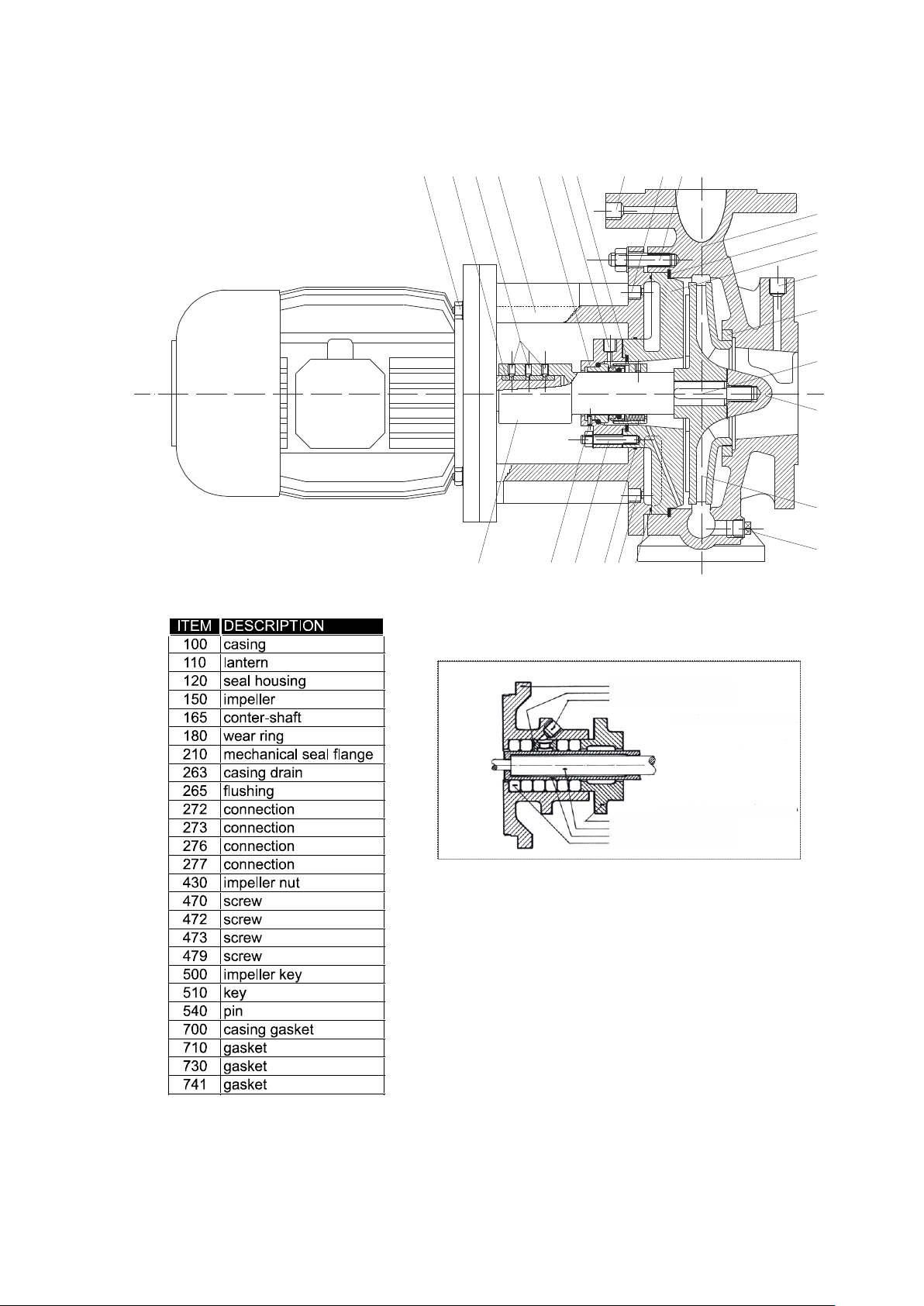
With the help of the cross-sectional drawing in the Appendix A the pump can be
dismantled as follows:
1. close discharge valve
2. close suction valve
3. avoid the possibility off turning on the pump
4. drain pump by opening drain plug (POS. 263)
5. undo auxiliary piping for cooling/flushing fluid.
6. dismantle the coupling guard
7. undo Nuts (POS: 472) on casing.
8. extract rotating assembly from casing.
9. remove the casing gasket (POS. 700)
10. check wearing rings if provided (POS. 180) and remove them if damaged
11. bring rotating parts in a clean place
If mechanical seal arrangement is double continue to point 15 otherwise skip to point 20
12. loose the 4 nuts of mechanical flange (POS. 473). Remove very carefully the seal
flange (POS: 210) using two levers
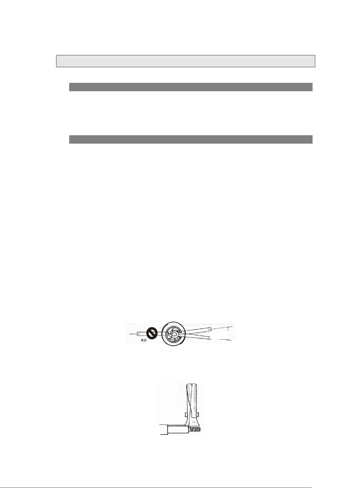
13. loose impeller nut (POS. 430) by means of two lever as shown in the following
picture:
14. remove the gasket (POS 720), and remove the impeller by means of an extractor
positioning the jaws on impeller blades
15. remove the impeller key (POS. 500) as shown in the following picture
16. remove the gasket (POS. 710)
Page 15

5. inspection and renewal of wear parts
14
17. In case of single mechanical seal arrangement without mechanical seal flange
(POS. 210), remove carefully the stuffing box (POS. 120) and the mechanical seal
by means of 2 levers. If the mechanical seal is double the stuffing box in
independent from mechanical seal. Remove then the mechanical seal, the shaft
sleeve and the mechanical seal flange.
5.3. REASSEMBLY OF THE PUMP
The reassembly of the pump is carried out in the reverse order. To ensure trouble free
running the pump should be reassembled with the greatest of care.
The following points should be carefully observed.
a) Take care not to damage the mechanical seal when fitting.
b) The shaft sleeve of soft packed pumps should be free from wear grooves and
remnants of old packing.
c) Carefully fit keys and shaft sealing rings, making sure that the gaskets and sealing
faces are clean.
d) By pumps with open impellers the clearance between the impeller and wear plate
must be adjusted to approx. 1 mm by means of screws
Page 16
15
2
6
3
1
5
0
4
3
0
5
0
0
1
8
0
2
7
6
1
0
0
4
7
2
7
3
0
2
6
5
1
1
0
5
3
1
1
6
5
5
4
0
4
7
3
2
1
0
7
4
1
2
7
3
1
2
0
7
4
0
7
0
0
2
7
7
2
7
2
4
7
9
5
1
0
Packing Gland Execution
lantern ring execution
standard execution
flushing
lantern ring
stuffing box
packing seal
shaft sleeve
shaft
gland
APPENDIX A – SECTIONAL DRAWING – standard execution
Page 17

16
Page 18

17
RECOMMENDED SPARE PARTS FOR 2 YEARS WORKING
POS.
DESCRIPTION
No. OF PUMPS
1 2 3 4 5/6
7/8
9
10 (+)
150
IMPELLER
0 1 1 2 2 2 3
30%
180190
WEARING RINGS (IF
PROVIDED)
1 2 2 2 2 3 4
50%
170
SHAFT SLEEVE (IF
PROVIDED)
1 1 1 1 1 2 2
20%
700710720730
GASKET SET
2 5 7 9 10
10
12
120%
-
MECHANICAL SEAL
1 2 3 4 5 7 9
100%
APPENDIX E – RECOMMENDED SPARE PARTS
Page 19
18
P
x
P
y
P
z
M
x
M
z
P
y
M
y
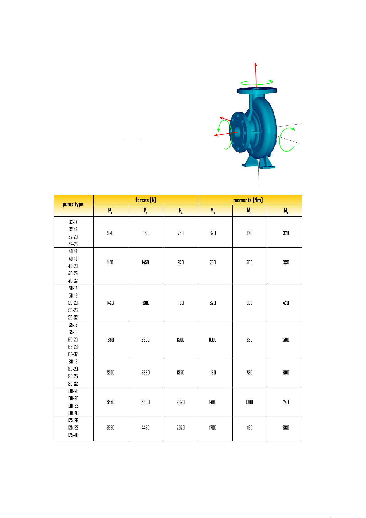
Forces and moments acting on the pump flanges due to pipe loads may induce
misalignment of pump and driver shafts, deformation and over stressing of
pump casing, or over stressing of the fixing bolts between pump and
baseplate.
Following table value are referred to steel construction, for different
materials than steel the corrective factor is given by:
200
)(TE
Km
where E (T) is Young modulus of the material in GPa at the considered
temperature
m
APPENDIX F – ALLOWABLE FORCES AND MOMENTS
Page 20

19
Page 21

POMPE IDROCHEMICAL
ZONA INDUSTRIALE
38076 LASINO – TRENTO – ITALY
TEL.: +39 0461 564359
FAX: +39 0461 564785
e-mail: [email protected]
www.idrochemical.com
 Loading...