

Page 1
2014-03-24
Color ID Card Printer
-Technical Manual
Page 2

2014-03-24
Copyright Notice
Users must respect the copyright laws applicable in their country.
This manual must not be photocopied, translated, reproduced or transmitted in whole
or in part for any reason and by the means that might be, albeit electronic or mechanical,
without the express, written authorization of IDP Corporation.
All information contained herein may be subject to modification without prior notice.
IDP Corporation accepts no liability for any possible errors herein, nor for any
accidental damage or damage caused through the dissemination or the use of this manual.
Trademarks
SMART is a trademark and IDP Card Printer is a registered trademark of IDP Corporation.
Windows is registered trademarks of Microsoft Corp. All other trademarks or
registered trademarks are marks of their respective holders. Smart Design is a trademark of
IDP Corporation.
Page 3

2014-03-24
3
1. Introduction
1.1 Printer Basic Information
◦ 1.1.1 Printer Outside Features
◦ 1.1.2 Printer Inside Features
◦ 1.1.3 Ribbon Cartridge Feature
◦ 1.1.4 LED Status and Button Operation
1.2 Printer Installation and Instructions
◦ 1.2.1 Ribbon Installation
◦ 1.2.2 Card Thickness Adjustment
◦ 1.2.3 Cards Load
1.3 Printer Specifications
2. Main Parts
2.1 Sensors
2.2 Thermal Head and Rollers
2.3 Motors
2.4 PCBs
2.5 Wired Diagram
Page 4

2014-03-24
4
3. Parts Replacement
3.1 Covers
◦ 3.1.1 Side Cover Right / Left
◦ 3.1.2 LED-Button Unit
◦ 3.1.3 Stacker Unit
◦ 3.1.4 Front Cover
◦ 3.1.5 Rear Cover
3.2 Top Cover Unit
◦ 3.2.1 Thermal Print Head
◦ 3.2.2 Top Cover
◦ 3.2.3 Cooling Fan
◦ 3.2.4 Top Cover Frame
3.3 Main PCBs
◦ 3.3.1 Main Board
◦ 3.3.2 PCB Ribbon RF
Page 5

2014-03-24
5
3.4 Drive Unit
◦ 3.4.1 Main Drive
◦ 3.4.2 Belt Tension Setting
◦ 3.4.3 Ribbon, Head Down_Up Drive
3.5 Rollers
◦ 3.5.1 Cleaning Roller / Cleaning Roller Fixed
4 Administration
4.1 Setup
◦ 4.1.1 Overview
4.1.1.1 Function
4.1.1.2 Start
◦ 4.1.2 Printer Setup
4.1.2.1 Basic Setup
4.1.2.2 Expansion Setup
◦ 4.1.3 Printer Setup Adjustment
4.1.3.1 Printing Location
4.1.3.2 Printing Density
4.1.3.3 Ribbon Operation
4.1.3.4 Flipper
Page 6

2014-03-24
6
4.1.3.5 Magnetic Stripe
4.1.3.6 Thermal Print Head Replacement
4.1.3.7 Security
4.1.3.8 Etc.
4.2 Test
◦ 4.2.1 Overview
◦ 4.2.2 Basic Operation
4.2.2.1 Select
4.2.2.2 Control
4.2.2.3 Print
4.2.2.4 Allocation
4.2.2.5 Status
4.2.2.6 Message
◦ 4.2.3 Encoding
4.2.3.1 Magnetic Stripe
4.2.3.2 Contact SMART Card
4.2.3.3 Contactless (PC/SC) SMART Card
Page 7

2014-03-24
7
◦ 4.2.4 Status
4.2.4.1 Printer Status Code
4.2.4.2 Printer Error Code
4.3 Firmware
◦ 4.3.1 Overview
◦ 4.3.2 Automatic Update
◦ 4.3.3 Manual Update
5. Trouble Shooting
6.Appendix
A. Service Parts List
B. Expanded View
C. Option Unit Placement & Wiring
Page 8
2014-03-24
8
1.1 Printer Basic Information
1.1.1 Printer Outside Features
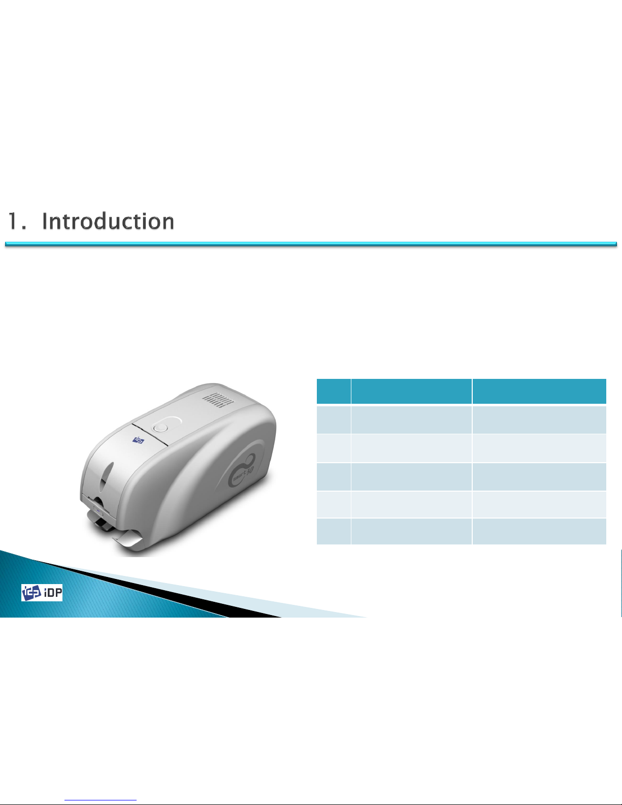
This SMART-30 Card Printer takes a power via the adaptor provided with the printer. Using USB port, it
communicates with user’s PC. For the user’s convenience, the printer working status can be seen by LED and most of
the operations can be controlled by buttons.
The following shows the external functional features found on your Smart Printer
1.1 Printer Basic Information
Fig.1-1 Printer Front/Side Features
No. Name Function
①
TOP COVER OPEN
BUTTON
Open Top Cover.
②
HOPPER COVER
Load the cards for
printing.
③
LED & BUTTON
Display printer status and
control printer
④
SIDE COVER
⑤
STACKER Enable to remove Stacker
①
③
②
④
⑤
Page 9
2014-03-24
⑧ ⑨ ⑩
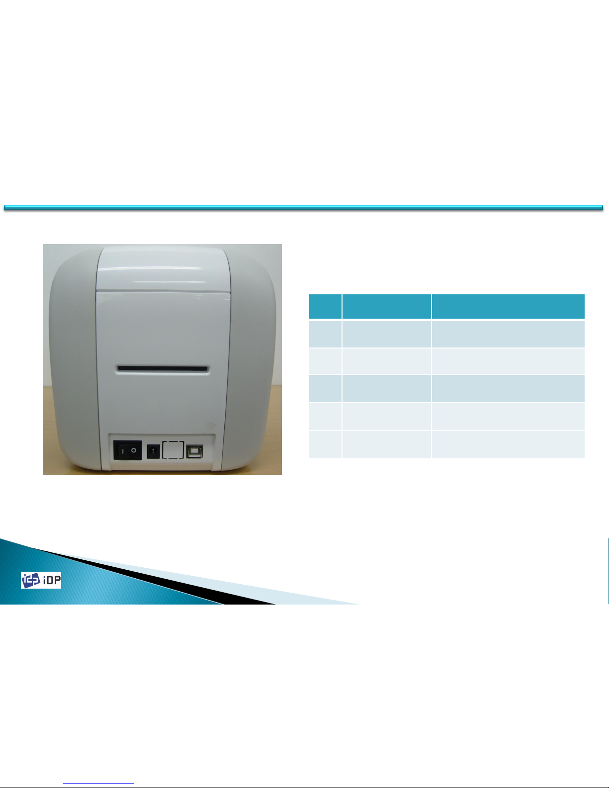
Fig.1-2 Printer Read Features
No. Name Function
⑥
REAR CARD
OUTLET
Eject Error Card
⑦
POWER SWITCH Printer On/Off
⑧
DC POWER
CONNECTOR
Connect DC power (Adapter)
⑨
USB PORT
Communicate with PC using
USB cable
⑩
ETHERNET PORT
(OPTION)
Use it after removing the
ethernet port protector
9
⑥
⑦
1.1 Printer Basic Information
Page 10
2014-03-24
10
1.1.2 Printer Inside Features
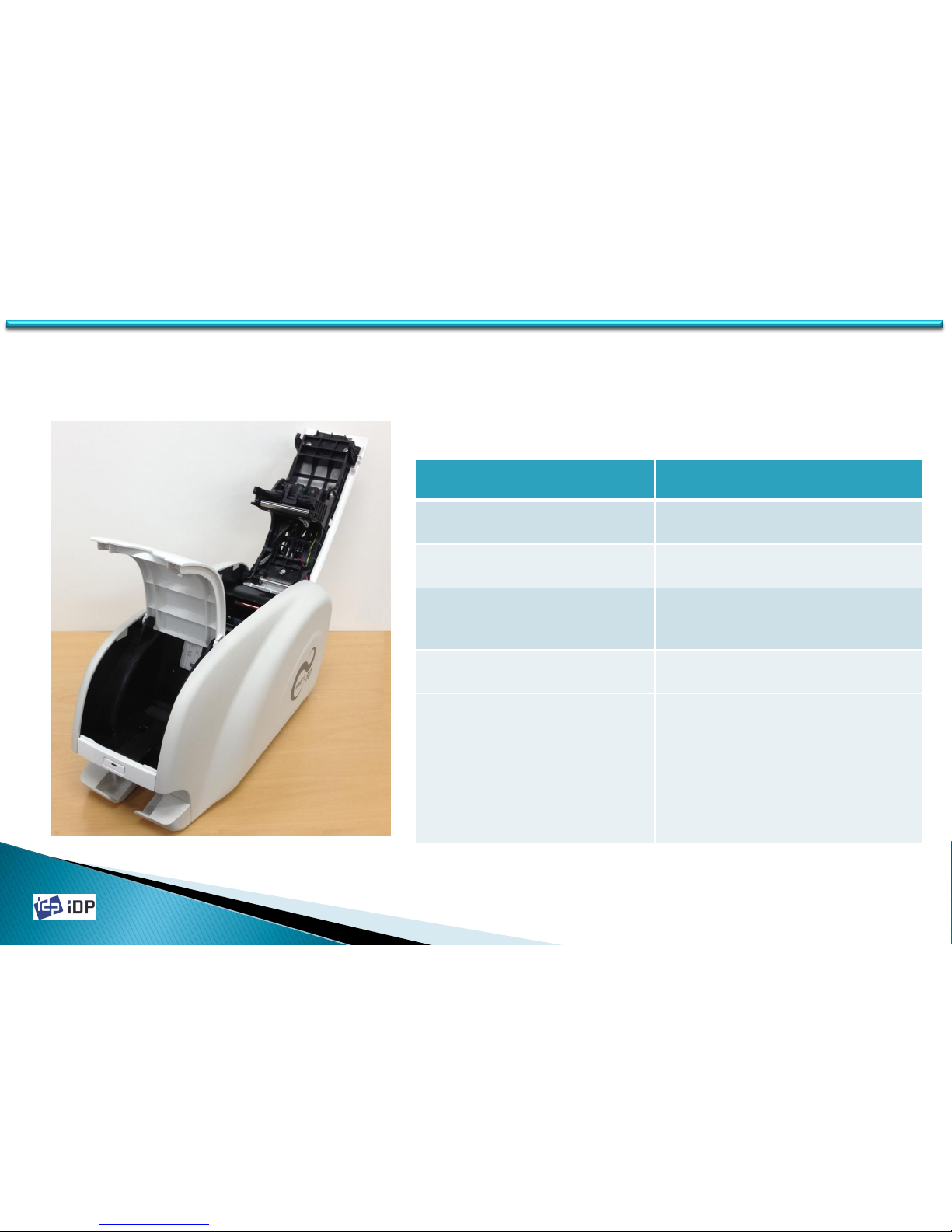
Smart Printer adopts a semi-permanent cartridge to install a Ribbon. The following shows the internal components
and functional features found on your Smart Printer.
No. Name Function
①
STACKER
Stack printed cards and can be
removed.
②
HOPPER
Load new cards for printing and
encoding.
③
CARD THICKNESS
CONTROL BRACKET
Loosen screws and adjust bracket
according to card thickness.
④
RIBBON CARTRIDGE Install ribbon and cleaning roller
⑤
THERMAL PRINT HEAD
This enables the Cards to be
printed.
Caution! Do not contact the
surface of the printer head with
fingers or a sharp metal object to
avoid degrading print quality or
damaging printer head
permanently.
⑤
①
Fig.1-3 Printer Inside Features
②
③
④
1.1 Printer Basic Information
Page 11
2014-03-24
11
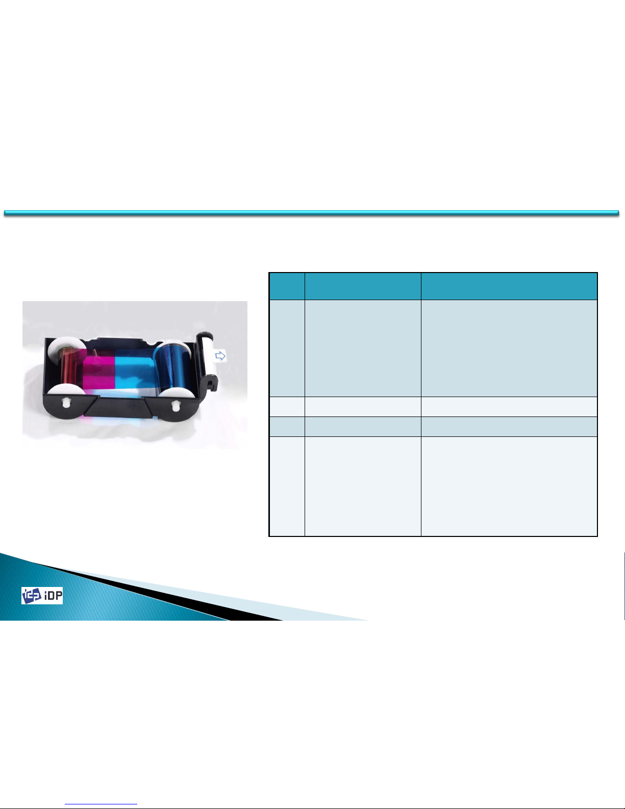
1.1.3 Ribbon Cartridge Feature
①
②
③
④
1.1 Printer Basic Information
No. Name Function
①
Ribbon Cartridge
Install a Ribbon and a disposable
cleaning roller provided with the
Ribbon. (Important! This semipermanent ribbon cartridge is a
component of the printer. Printer
does not operate if it is broken or
damaged. In this case, please
contact printer reseller.)
②
Ribbon Take-Up Core Collect the ribbon used in printing
③
Ribbon Supply Core Provide the ribbon for printing
④
Disposable
Cleaning Roller
It removes dust in the surface of
card to improve print quality before
the card is printed. It should be
changed together with the Ribbon.
(Caution! This disposable cleaning
roller is provided with the Ribbon. If
this is not changed, print quality
mighty be degraded. )
Fig.1-4 Ribbon Cartridge
Page 12
2014-03-24
12
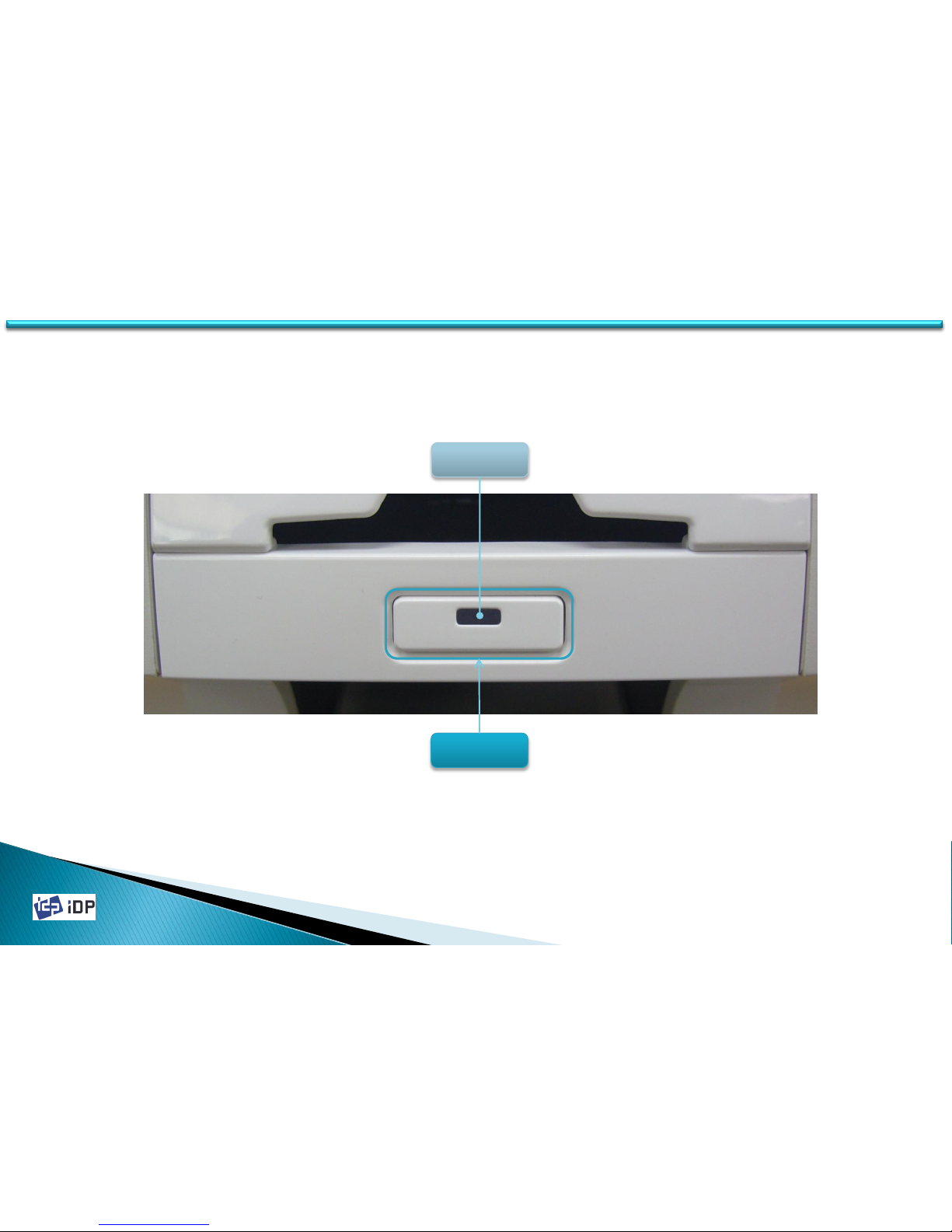
1.1.4 LED Status and Button Operation
SMART-30 Printer shows the real-time working status to user using LED and can be controlled by button according
to each working status.
BUTTON
LED
1.1 Printer Basic Information
Page 13
2014-03-24
13
Please refer LED status and button operation. SMART-30 shows status messages on watchman that installed with
printer driver.
No
Watchman LED
Button
State
상세 설명
1
INIT Error xx
< Retry >
RED
Blink
Retry Error occur in initializing
Error code is displayed when SMART-30 can’t be initialized . Please press
button to re-initialize.
2
SMART - 30
System Ready
BLUE
On
Power System Ready Status SMART-30 is ready. If you press button, power is turned on or off.
3
S m a r t
Unlock Please..
BLUE
On
Printer Locked Status
When activating Physical Key option and SMART-30 is locked by the key,
or activating Root/User authentication option and SMART is locked by the
password. Printer is locked so can’t be operated
4
S m a r t
Verify your PC
BLUE
On
Need to Verify using
Authenticated PC.
When activating PC authentication option and using SMART-30 in other
PC. Printer can’t be operated
5
S M A R T
Printing!
BLUE
On
In Printing SMART-30 is in printing.
6
Print Error xx
< Cancel >
RED
Blink
Cancel
Error occur in printing or
Moving card
Error occur in printing or moving card. If pressing button,, printing will
be canceled.
7
Top Cover Open
< Eject >
RED
Blink
Moving
Card
Top Cover Open Top cover is opened. If pressing button, SMART-30 eject card.
1.1 Printer Basic Information
Page 14
2014-03-24
No Watchman LED
Button
State
상세 설명
8
Check Please..
Ribbon Not Found
RED
Blink
Ribbon
Research
Ribbon is not installed or
not searched
Fail to ribbon search. Check the ribbon installed status and if there is nor ribbon,
please reinstall ribbon in printer.
9
Check Please..
Ribbon Zero
RED
Blink
Ribbon
Research
All ribbons are used
Ribbon remains is zero. Need to change the ribbon. If pressing button, SMART30 search ribbon again.
10
Check Please..
TPH Not Found
RED
Blink
Thermal Print Head is
not installed
When the thermal Print Heat is not installed or disconnected to head cable, this
message is displayed. Please power off SMART printer and check the thermal
head installation status.
11
Card Out Error
< Cancel >
RED
Blink
Initializing
Card Out Error
(Check card in Printer)
When there is printing error , the card is not ejected after pressing button.
12
Board Test Mode
Wait
RED
Blink
Printer Test Mode SMART-30 is on test mode that the sensors and motors of printer are tested.
14
1.1 Printer Basic Information
Page 15
2014-03-24
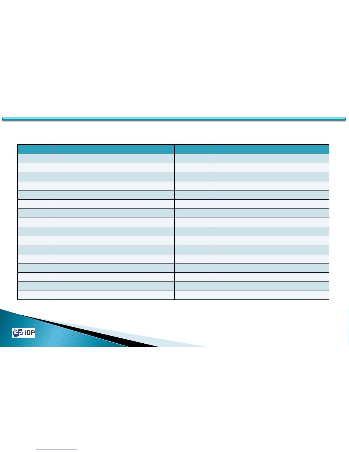
Printer Error Code
15 15
1.1 Printer Basic Information
Error Code Details Error Code Details
00 Card In Error 16 Ribbon Search Error
01 Card Move Center Error 17 Ribbon Move Error
02 Card Out Error 18 No Thermal Print Head Installed
03 Card Move Magnetic Error 19 Thermal Print Head Overheat
04 Card Move IC Contact Error 20 No Ribbon Installed
05 Card Move RF Error 21 Printing Data Error
06 Card Move Error from Printer to Flipper 22 Card Back Out Error
07 Card Move Error from Flipper to Printer 23 Magnetic Data Removing Error
08 Thermal Print Head Up Error 24 Wrong Printer Password
09 Thermal Print Head Down Error 25 Magnetic Track 1 Read Error
10 IC Contactor Up Error 26 Magnetic Track 2 Read Error
11 IC Contactor Down Error 27 Magnetic Track 3 Read Error
12 Flipper Top Error 28 Printer Lock State
13 Flipper Bottom Error 29 Printer Spool Full
14 Error in Printing 30 Undefined
15 Magnetic R/W Error 31 Undefined
Page 16
2014-03-24
16
1.2 Printer Installations and Instructions
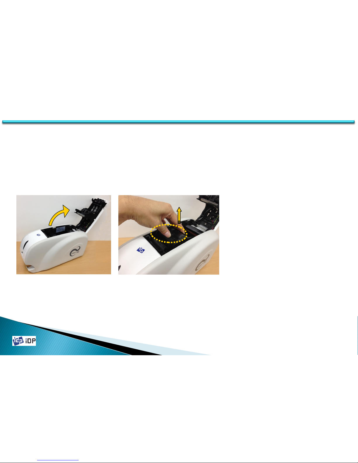
1.2.1 Ribbon Installation
Before printing, prepare the related items such as a card, a ribbon and a cleaning roller. In this section, we invite you
to know the proper method to install the ribbon and the cleaning roller into the printer.
1.2 Printer Installation and Instructions
Fig.2-1 Open Top Cover Fig.2-2 Take out ribbon cartridge
1. Turn off the power of printer
2. Open the top cover of printer by
pressing the top cover open button
(Refer to Fig.2-1).
3. Take out the ribbon cartridge (Refer to
Fig.2-2).
Page 17
2014-03-24
17
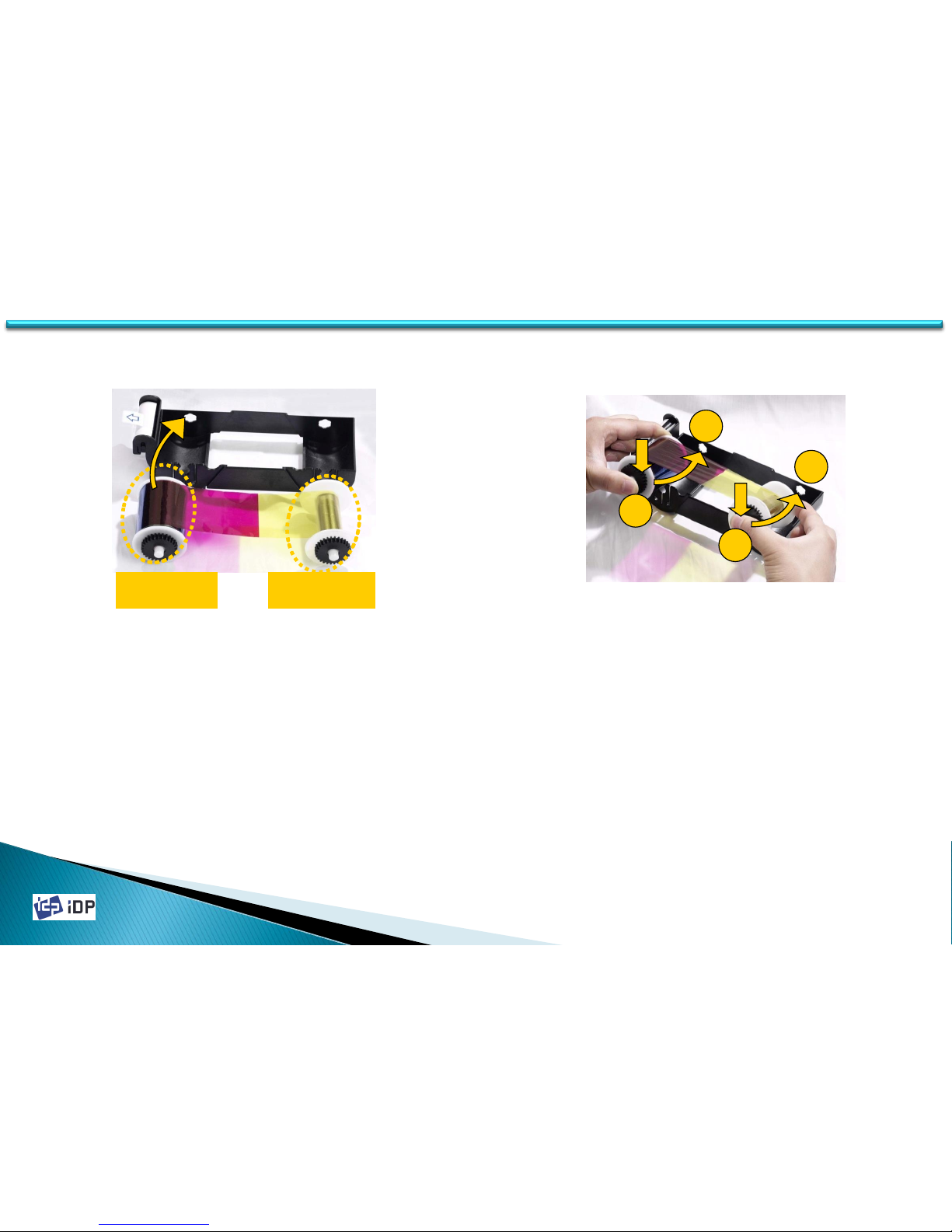
Ribbon Supply
Core
Ribbon Take-up
Core
Fig.2-3 Prepare the ribbon
1
2
3
4
Fig.2-4 Install the ribbon]
5. Insert the supply side of the ribbon to
no.1 hole and press the opposite(no.2)
until it clicks. Insert the take-up side of
the ribbon to no.3 and no.4 by the same
way. And fasten the ribbon.
※ Caution! If the ribbon is not fastened, a
rolling up error might happen.
4. Prepare the ribbon before inserting it into
the ribbon cartridge.
※ Refer to the illustration on the inside of the
cartridge.
1.2 Printer Installation and Instructions
Page 18
2014-03-24
18
1.2 Printer Installation and Instructions
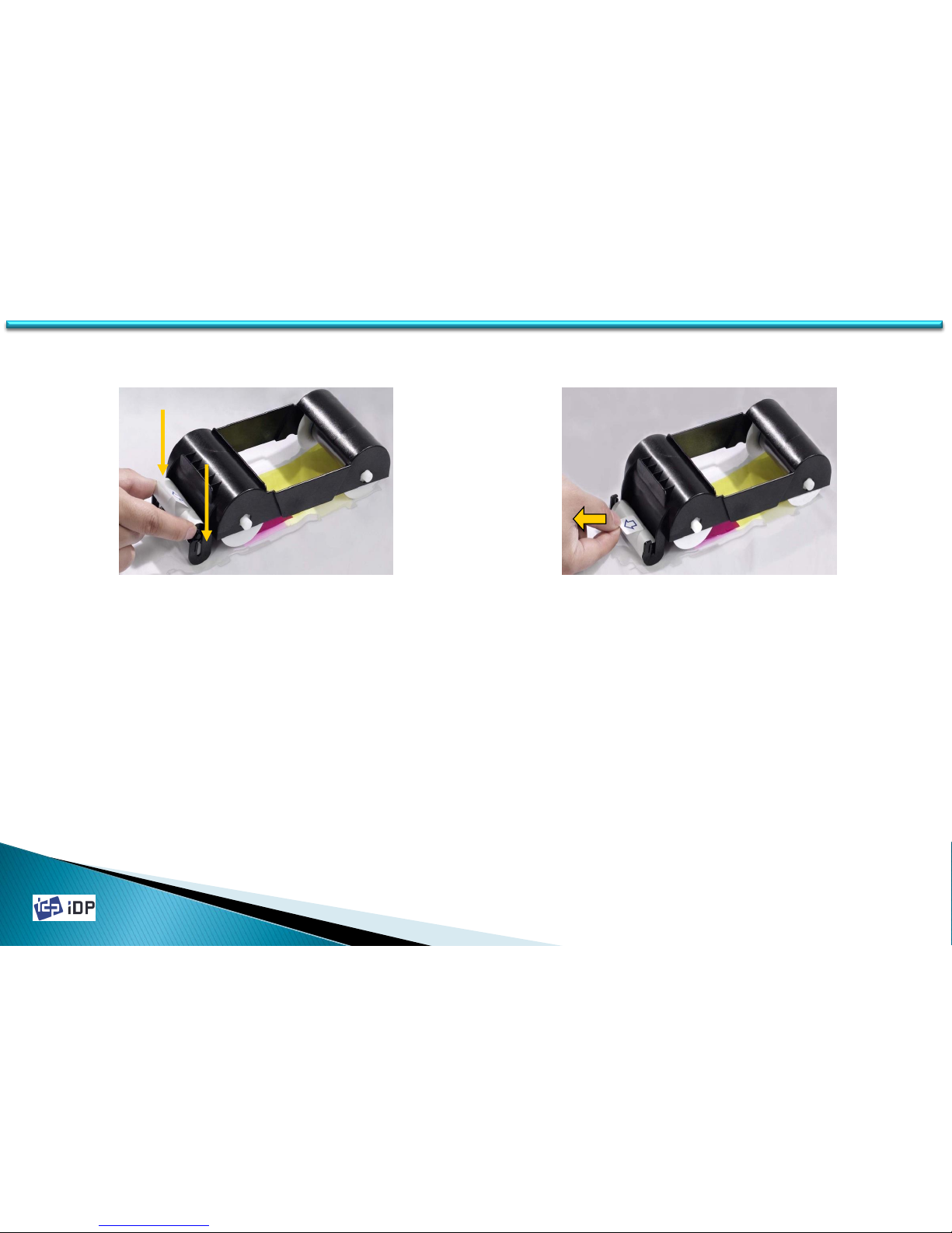
6. Install the disposable cleaning roller to
the ribbon cartridge.
Fig.2-5 Install the cleaning roller
Fig.2-6 Peel the protective wrapper
7. Peel the protective wrapper from the
cleaning roller.
To avoid contamination, always hold the
cleaning roller. Be careful to touching,
dust and contamination because it is
adhesive.
※ Caution! Do not use without peeling off the
protective wrapper. The cleaning roller do
not perform its function.
Page 19
2014-03-24
19
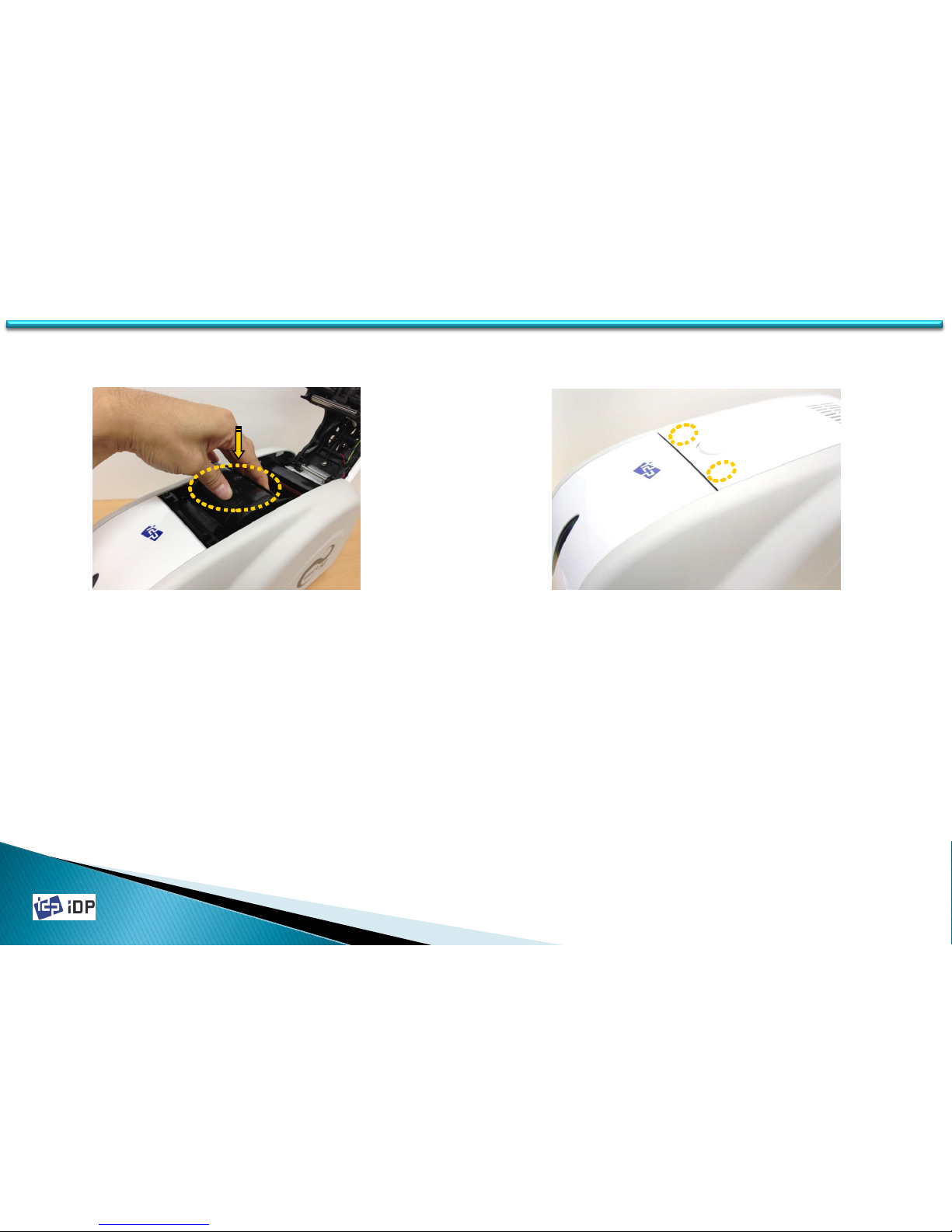
Fig.2-7 Install the ribbon cartridge
Fig.2-8 Close Top Cover
1.2 Printer Installation and Instructions
8. Install the ribbon cartridge to the printer
after install the ribbon and cleaning roller
to the cartridge.
9. Close the top cover until it clicks.
(If it is not closed, check the installation
state of the ribbon cartridge.)
Page 20
2014-03-24
20
1.2.2 Card Thickness Adjustment
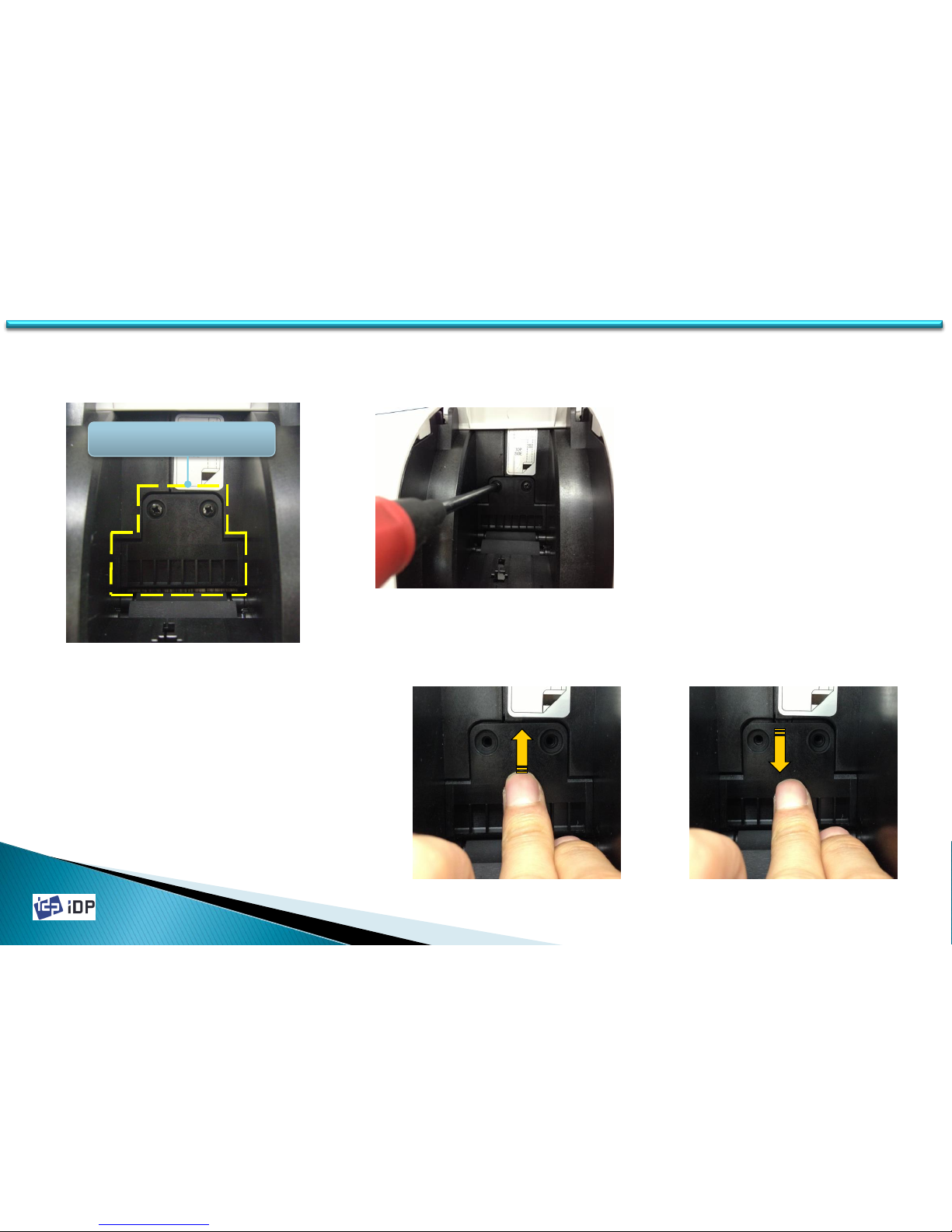
This session shows how to adjust the card thickness for taking a card into printer properly.
1. If the hopper cover is closed, please open it.
2. Please check the Hopper Gate is properly
adjusted to your card’s thickness.
(Caution! If the adjusted card thickness is
thinner than your card’s thickness, SMART-30
can’ take a card into printer. If the adjusted card
thickness is thicker than your card’s thickness,
several cards may be taken into printer at the
same time and error occur.)
Fig.2-9 Card Thickness Adjustment 1
Card Thickness Adjustment
(HOPPER GATE)
3. For Adjusting card thickness,
please loosen two screws with a
phillips screwdriver, and push up
or down the HOPPER GATE, and
tighten the crews(Fiz.2-10).
(Card Thickness 0.76mm is default)
3. For 0.76mm(30mil) cards, please
push up the HOPPER GATE and
tighten the screws(Fig.2-11)
4. For 0.38mm(15mil) cards, please
push down the HOPPER GATE and
tighten the screws(Fig.2-12)
Fig.2-10 Card Thickness Adjustment 2
Fig.2-11 For 0.76mm Cards Fig.2-12 For 0.38mm Cards
1.2 Printer Installation and Instructions
Page 21
2014-03-24
21
1.2.3 Cards Load
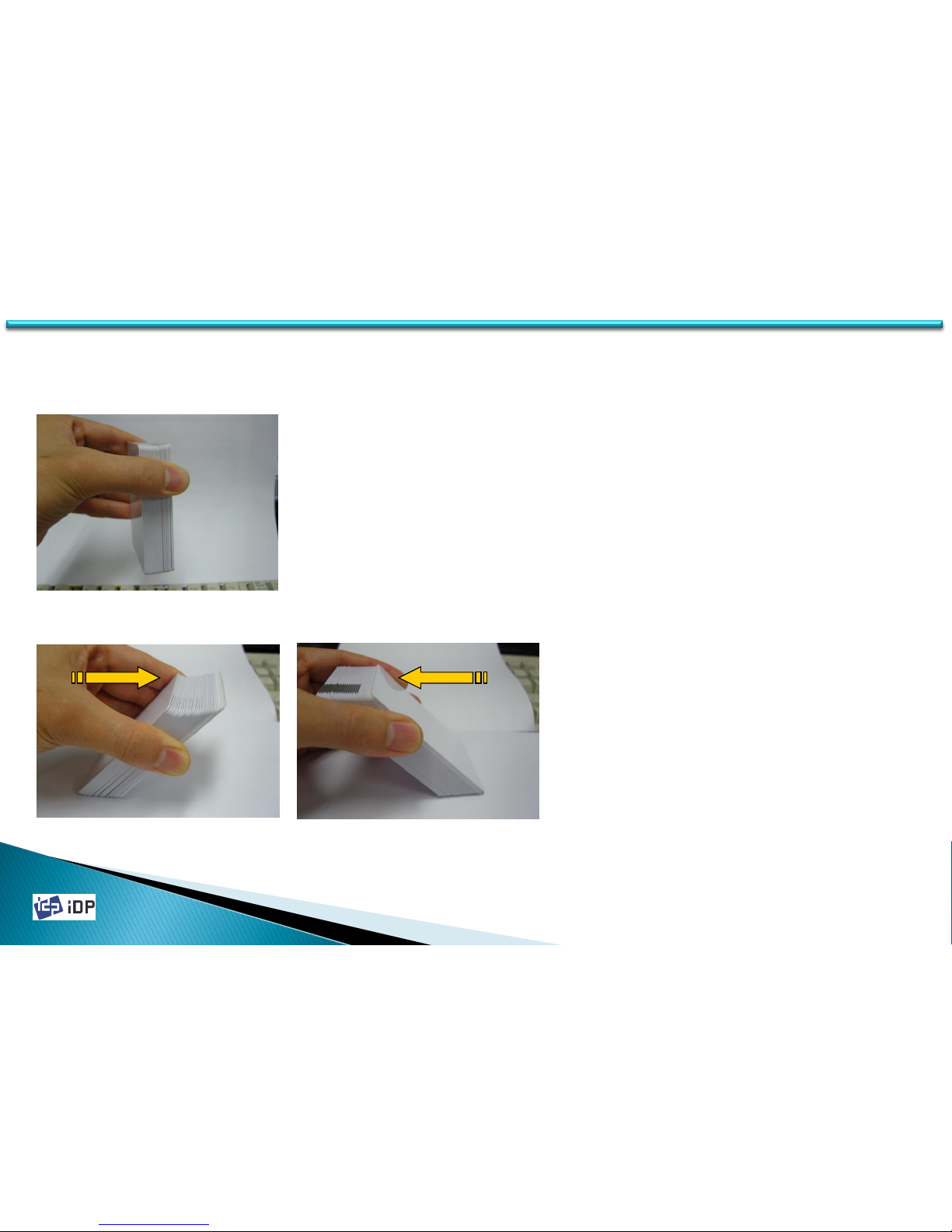
This section shows how to load plastic cards into the Smart Printer.
2. Push the stack back and forth to an angle
of about 45° vertically.
※ Caution! Static charge makes cards stuck
with significant adhesive force. These
cards must be physically separated from
each other before inserted into the feeder.
If not separated, feeding or printing
problems may occur.
Fig.2-14 Prepare cards 2
Fig.2-15 Prepare Cards 3
1. Properly hold cards by sides (Fiz.2-13).
※ Caution! Do not bend the cards and do not
touch the surface of the cards.
Fig.2-13 Prepare Card 1
1.2 Printer Installation and Instructions
Page 22
2014-03-24
22
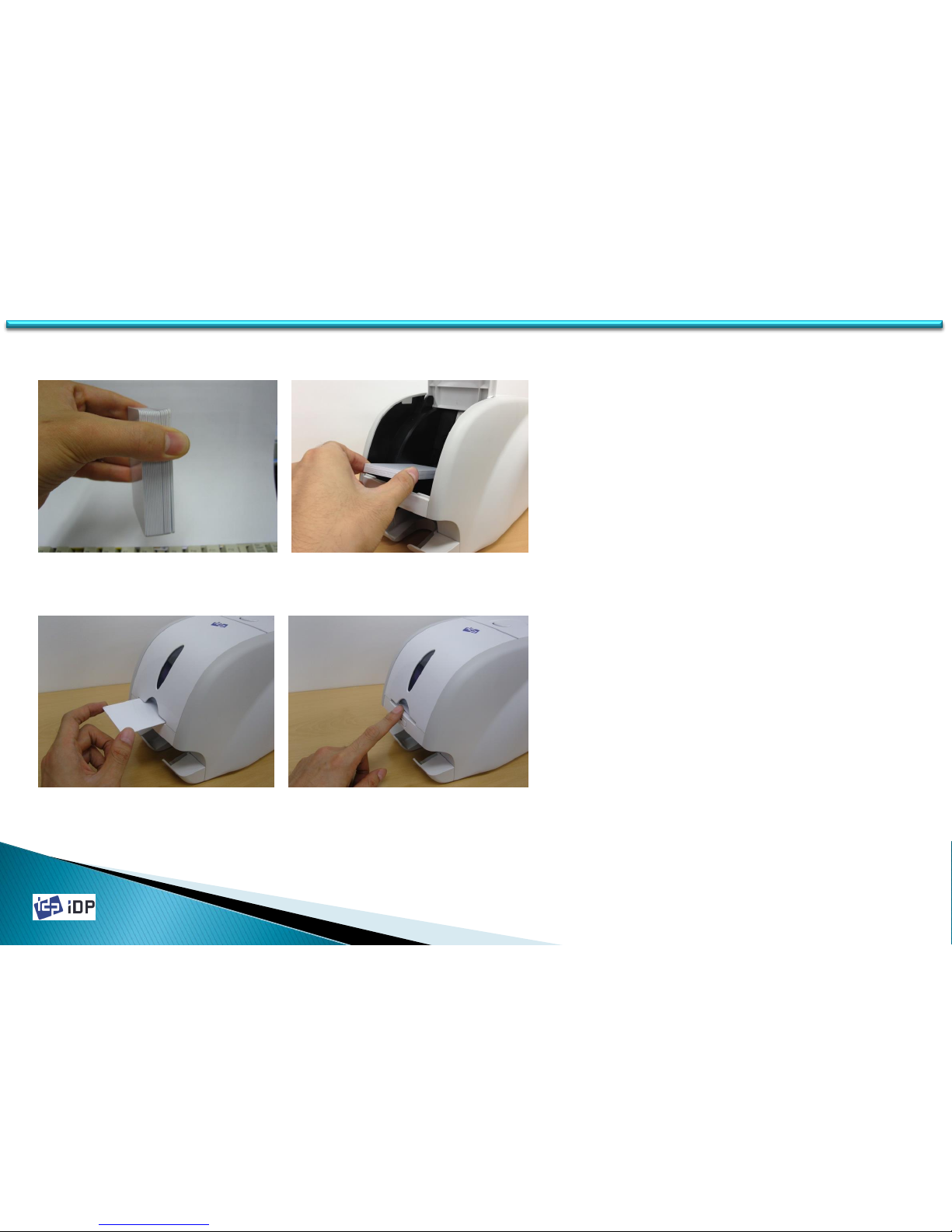
5. In case of one card insert, refer to Fig.218 and Fig.2-19, and insert the card into
the hopper.
(Please push a card until you can’t push it
any more.)
Fig.2-18 Cards Load 3
Fig.2-19 Cards Load 4
3. Restore the cards stack to its original
condition.
4. Place the cards to the hopper and close the
hopper cover.
Fig.2-16 Cards Load 1 Fig.2-17 Card Load 2
1.2 Printer Installation and Instructions
Page 23
2014-03-24
23
1.3 Printer Specifications
1.3 Printer Specifications
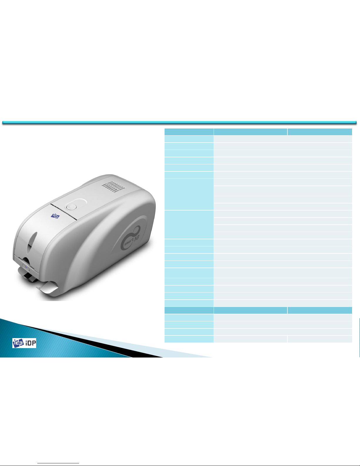
Product Specification
SMART-30S
SMART-30D
Card Types
PVC, Polyester Cards with polis hed PVC finish
Printing Method
Dye-Sublimation / Resin Thermal / Edge-to-Edge
Card Format
ISO CR80 (54mm x 86mm)
Card Thickness
0.38mm(15mil) ~ 0.76mm(30mil)
Resolution
300 dpi
Memory
32MB
Printing Speed
Color (YMCKO ) : 128 card/hour
Color (YMCKOK) : 100 card/hour
Black Overlay (KO) : 300 cards/hour
Mono (Black) : 600 cards/hour
Ribbon Capacity
Color (YMCKO) : 250 cards/roll
Color (YMCKOK) : 200 cards/roll
Black Overlay (KO) : 600 cards/roll
Mono : 1200 cards/roll (Black, Gold, Silver)
Hopper & Stacker
Hopper : 100 cards, Stacker : 25 cards
Interface
USB
Display
1 LED Button
Power
Free Voltage (110/240V AC), 50~60 HZ, 45W
Dimension
172mm(W) x 190mm(H) x 377mm(D)
Operating Environment
Temperature : 20~35 ℃, Humidity : 20~80%
Weight
3.4 Kg
Agency Listing
MIC, CE, FCC
Printer Driver
Microsoft Windows 2000/2003/XP/Vista/7/8, Mac OS, Linux
Option
M/S Encoding Moudule
ISO 7811 (Track I,II,III Read / Write) Hico/LoCo
IC(Contact)Encoding Module
ISO 7816 (ID - 1)
RF Encoding(Internal)
ISO 14443 (Type A / B), ISO 15693, MIFARE
Flipper
Option
Default
Page 24
2014-03-24
24 24
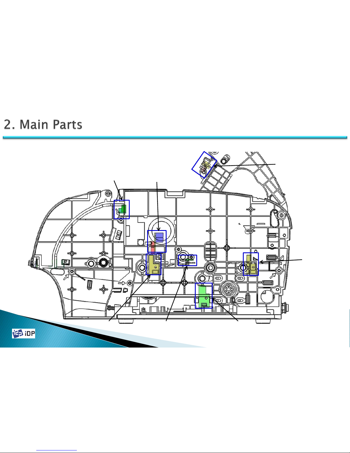
2.1 Sensors
2.1 Sensors
CASE OPEN
SENSOR
COLOR IN
SENSOR
CARD IN
SENSOR
ENCODER
SENSOR
HEAD UP-DOWN
SENSOR
COLOR OUT
SENSOR
CARD OUT
SENSOR
Page 25
2014-03-24
25 25
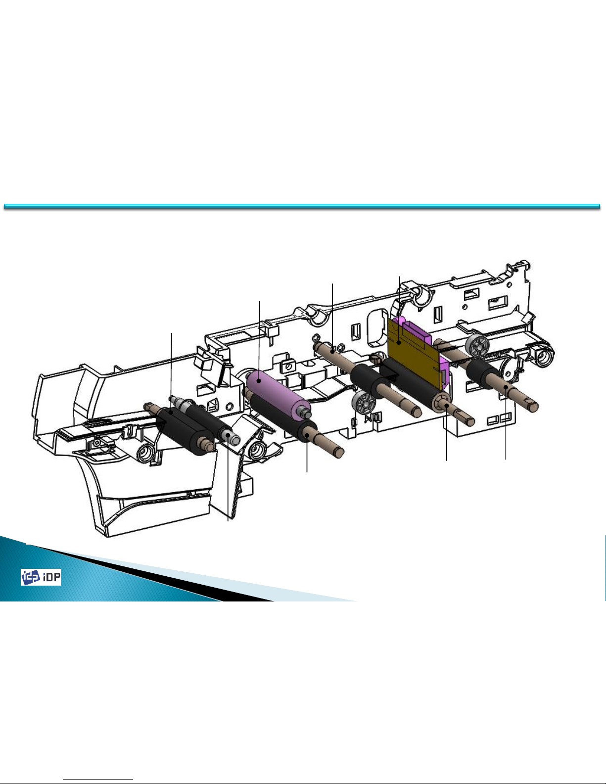
2.2 Thermal Head and Rollers
2.2 Thermal Head and Rollers
Cleaning Roller
Fixed
Cleaning
Roller
Card Supply
Roller
MS Roller
Thermal
Head
IC Roller
Printing
Roller
Card In
Roller
Page 26
2014-03-24
26 26
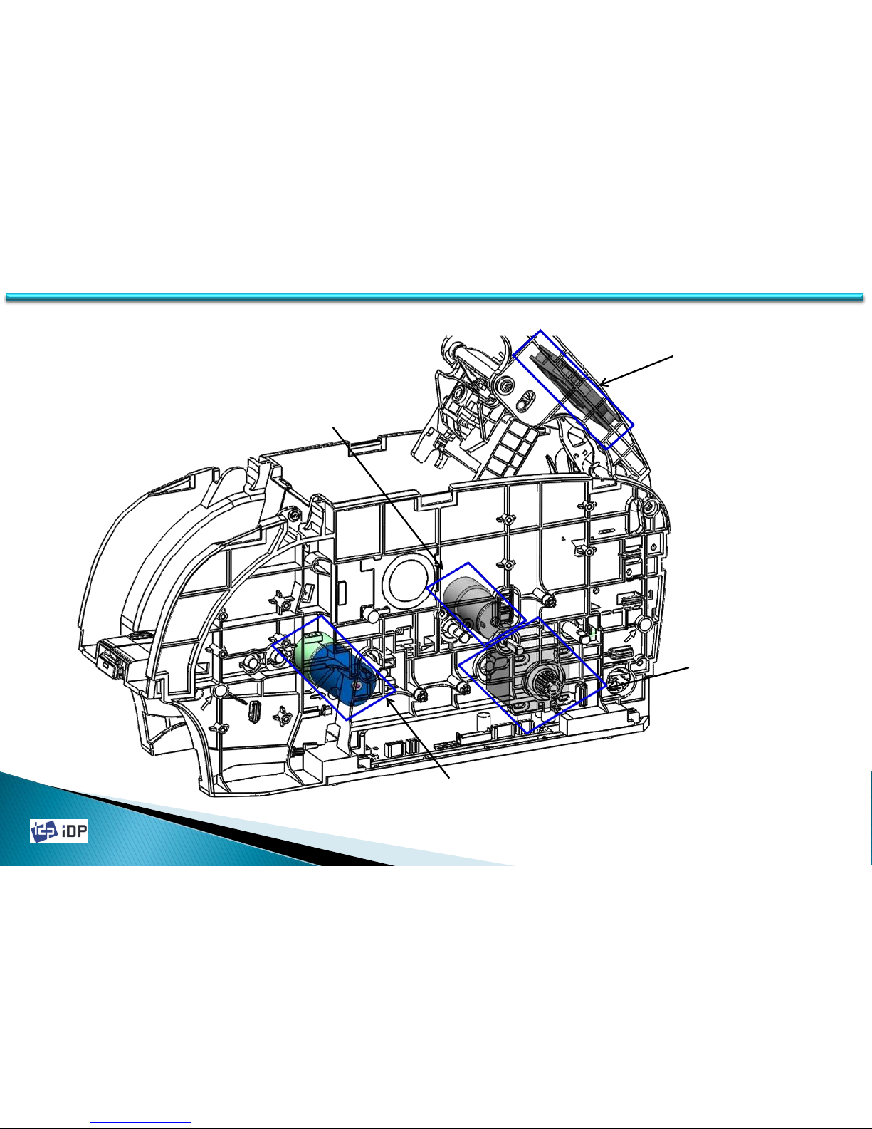
2.3 Motors
2.3 Motors
Main Driver
Step Motor
Ribbon Driver
Motor(DC)
FAN
Head Up_Down-
Hopper Motor(DC)
Page 27
2014-03-24
27 27
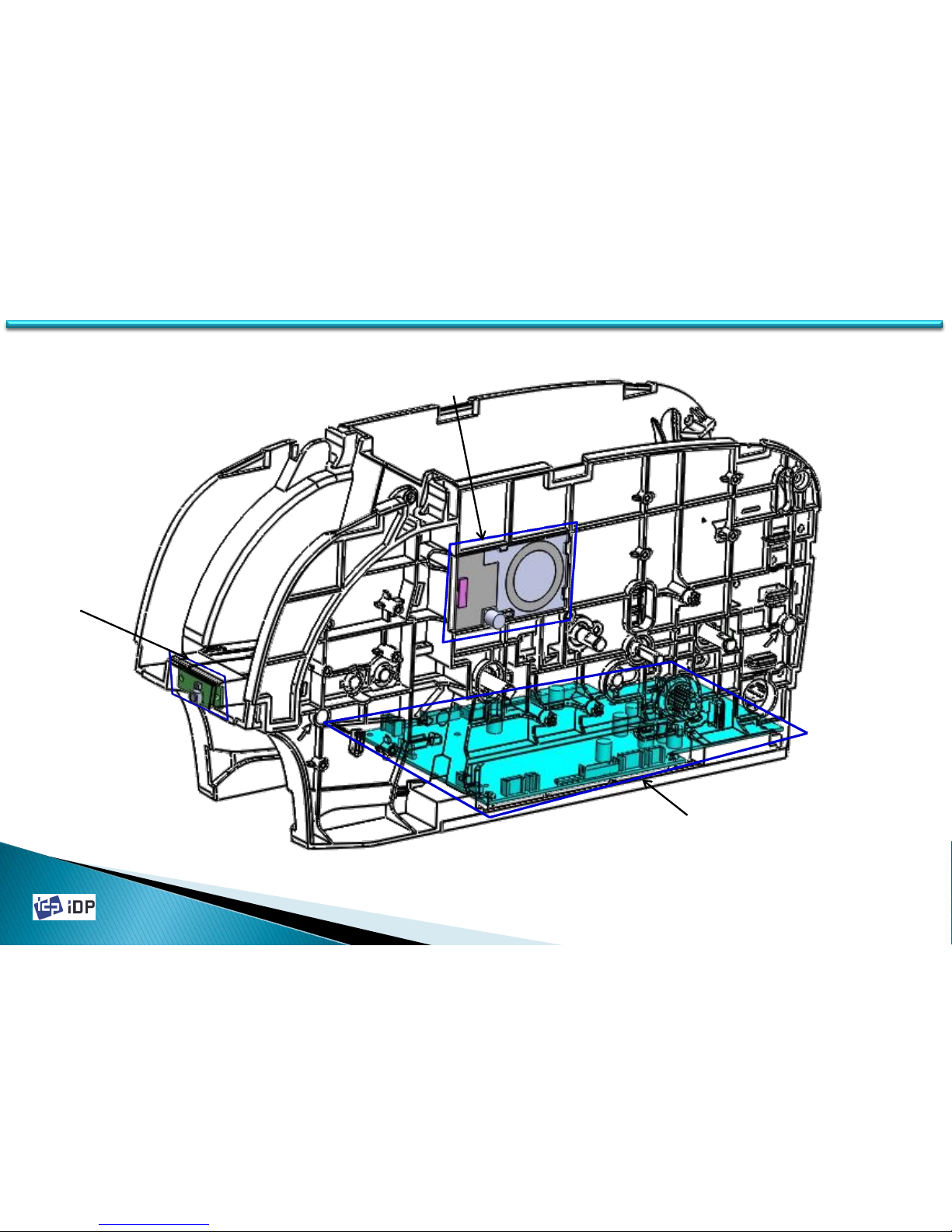
2.4 PCBs
2.4 PCBs
Front
Display
PCB
Main
Ribbon
RF
Page 28
2014-03-24
28
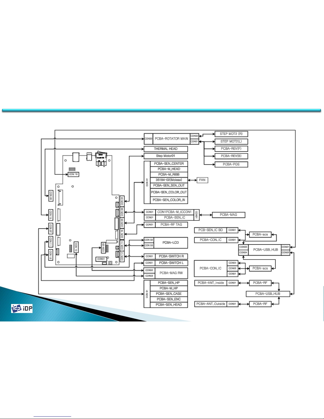
2.5 Wired Diagram
2.5 Wired Diagram
Page 29
2014-03-24
29
3.1 Covers
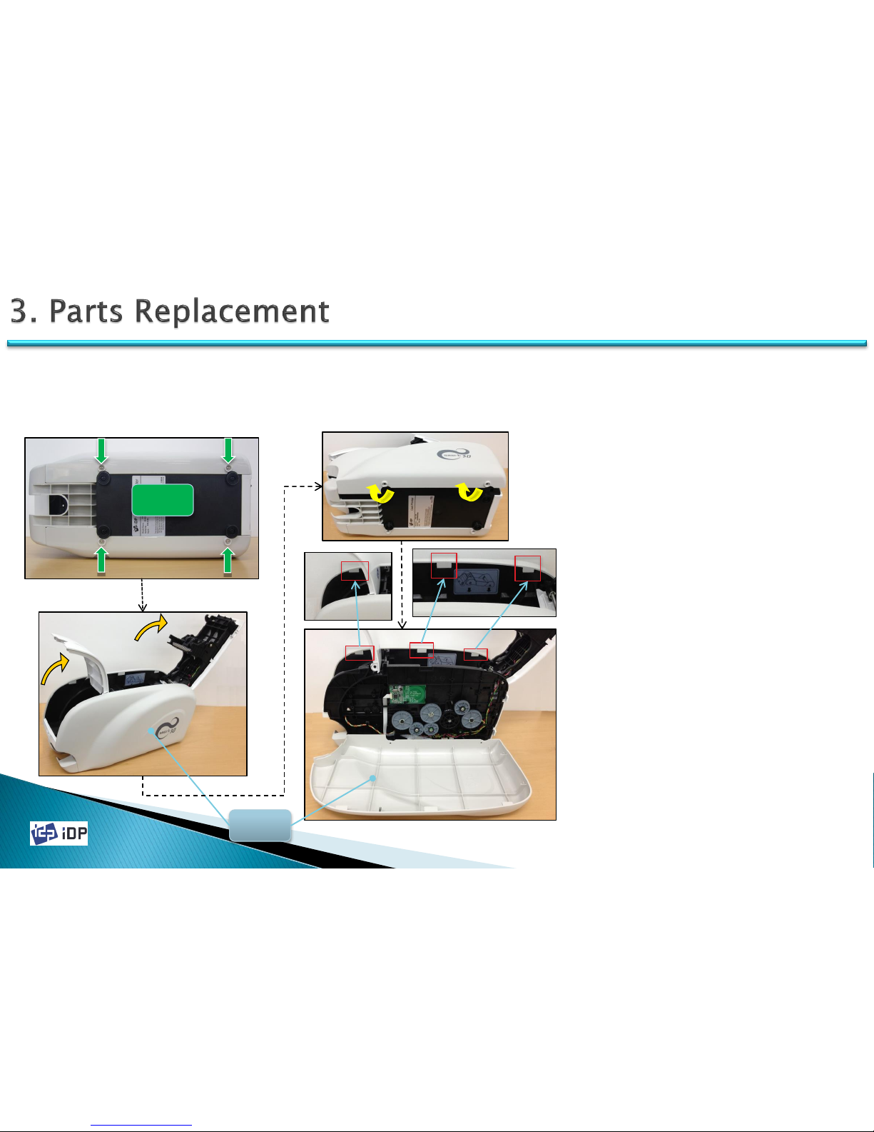
3.1.1 Side Cover Right / Left
3.1 Covers
Right
Cover
1. Loosen 4 screws on Bottom Frame.
2. Open Front Cover and Top Cover.
3. Grip the bottom part of right/left Side
Cover and pivot from upper part of
right/left Side Cover.
4. Upper part of right/left Side Cover is
connected with Side Plate, so push up the
Side cover paralleled to Side Plate direction
to disassemble.
Screw
Page 30
2014-03-24
30
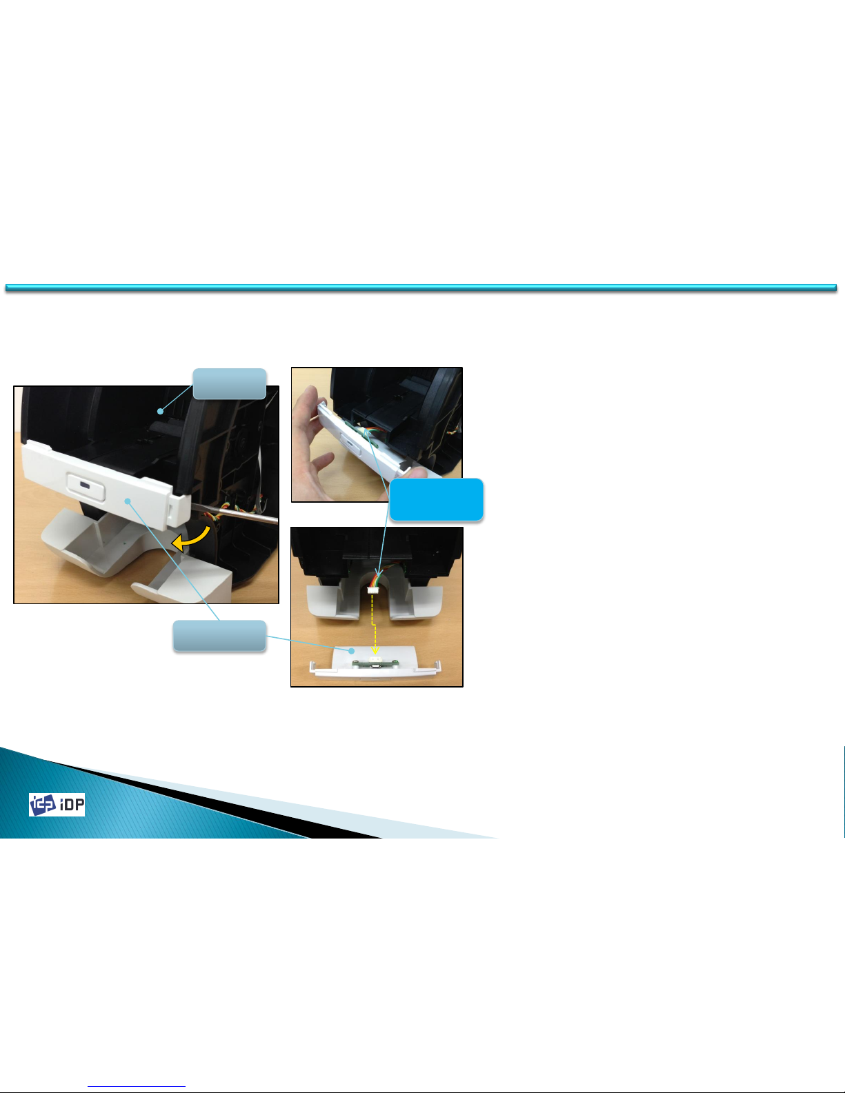
3.1.2 LED-Button Unit
3.1 Covers
1. Open the Front Cover.
2. Broaden the gab between LED-Button unit
and Main Frame using screw driver, and
then Hook is disassembled. At this time,
pull carefully the LED-Button unit to
disassemble it.
3. When pull out LED-Button unit, be cautious
not to make damage on the wire of LED-
Button unit.
4. Disconnect LED-Button Power wire from
LED-Button unit.
LED-Button
Unit
Button
Power wire
Front
Cover
Page 31
2014-03-24
31
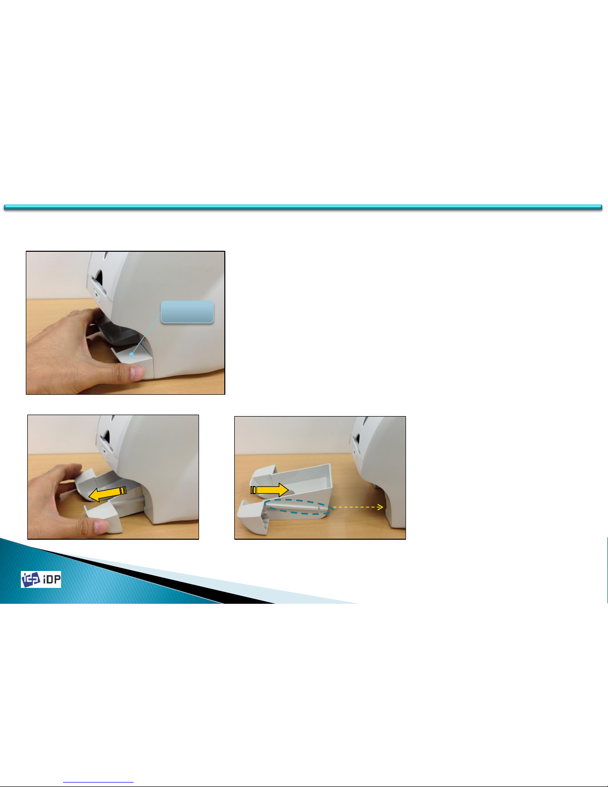
3.1.3 Stacker Unit
3.1 Covers
1. Hold both sides of the Stacker.
2. Pull out Stacker to separate it from printer.
At this time, hold printer to prevent printer
from moving.
3. When install Stacker into printer, push it
according the rail of the Stacker and the
track of printer.
4. Push the Stacker into printer until the
clicking sound.
STACKER
Page 32
2014-03-24
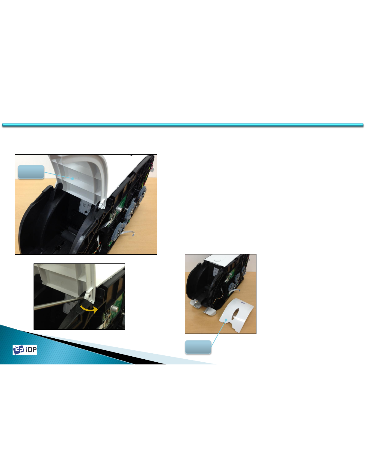
3.1.4 Front Cover
1. Open the Front Cover
2. Broaden the gab between Main Frame and
Front Cover using screw driver and
disassemble Front Cover from Main Frame.
Front
Cover
Front
Cover
32
3.1 Covers
Page 33
2014-03-24
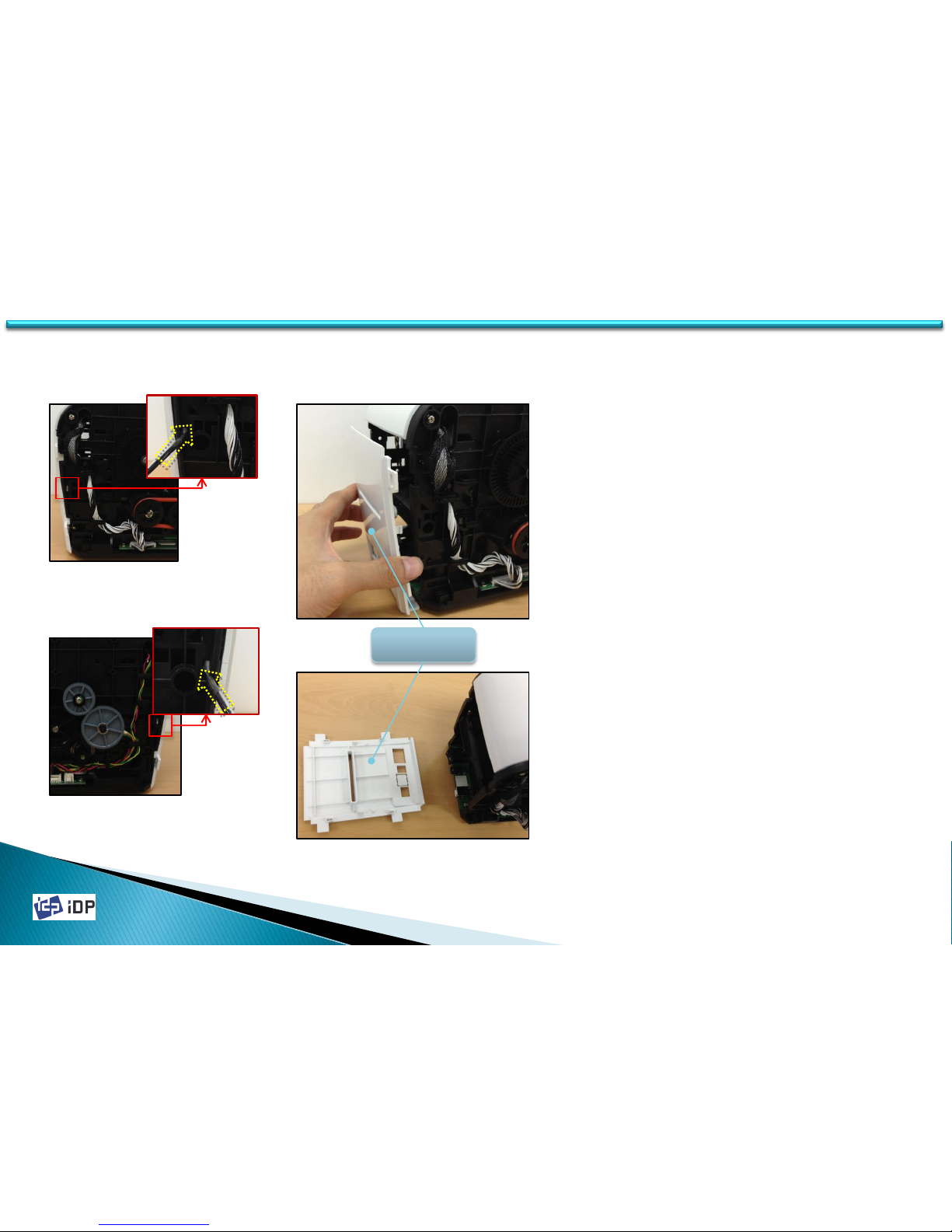
3.1.5 Rear Cover
1. Rear Cover is assembled to Main Frame by
Hook.
2. Unlocked the Hook on both side of the
Rear Cover using Screw Driver.
Left View
Right View
33
3.1 Covers
Rear Cover
Page 34
2014-03-24
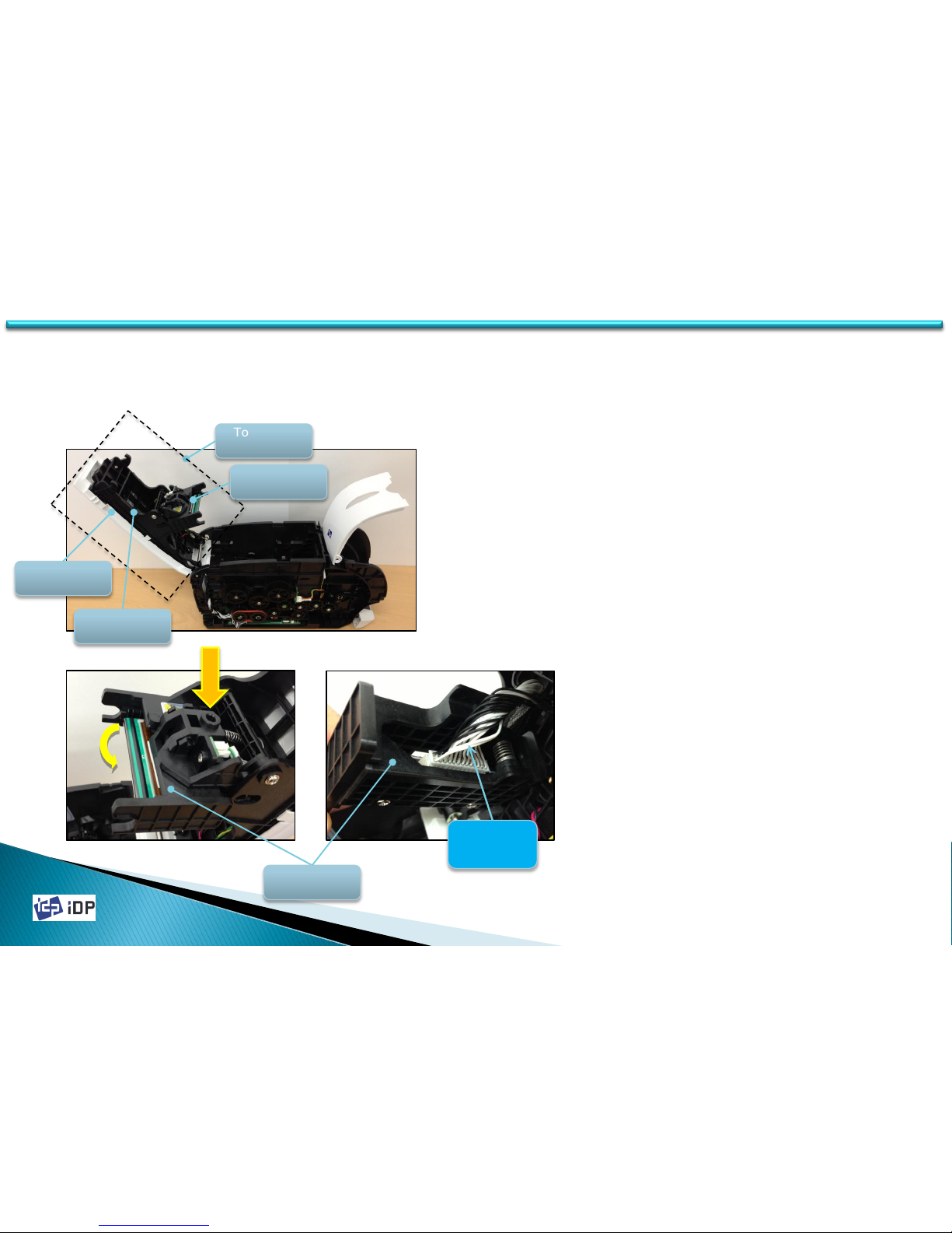
3.2 Top Cover Unit
3.2.1 Thermal Print Head
1. Printer Top Cover Unit consists of Top
Cover, Top Cover Frame and Thermal Print
Head.
2. Thermal Print Head is fixed by Hinge and
Hook on Top Cover Frame.
3. Press the push button of Hook, rotate the
thermal print head to the bottom side and
disassemble thermal print head from Top
Cover Frame.
4. Disconnect the Thermal Print Head Wire.
Top Cover
Unit
Thermal
Head
Push
Thermal
Head wire
Top Cover
Top Cover
Frame
Thermal
Head
34
3.2 Top Cover Unit
Page 35
2014-03-24
3.2.2 Top Cover
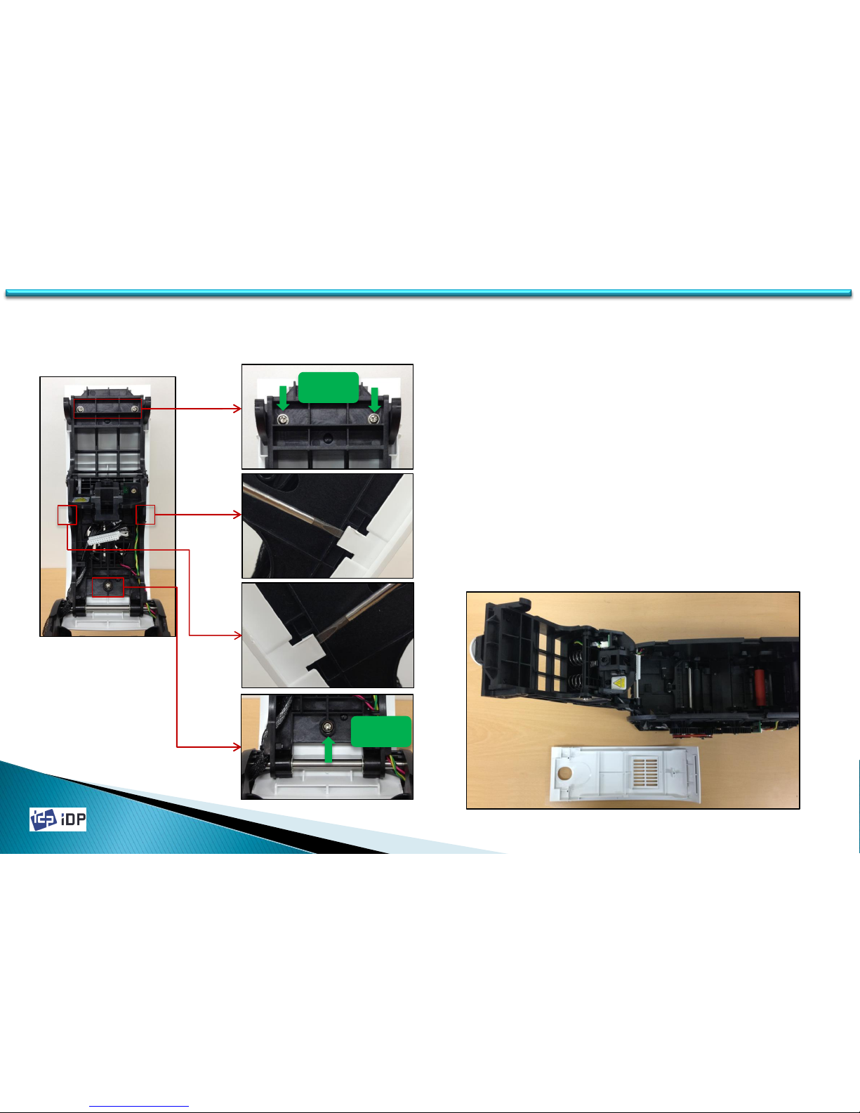
1. Top Cover is fixed to Top Cover Frame by 3
screws and 2 Hooks.
2. Loosen Screws and unlock Hooks using
screw driver, and then disassemble Top
Cover from Top Cover Frame.
Screw
35
3.2 Top Cover Unit
Screw
Page 36
2014-03-24
36
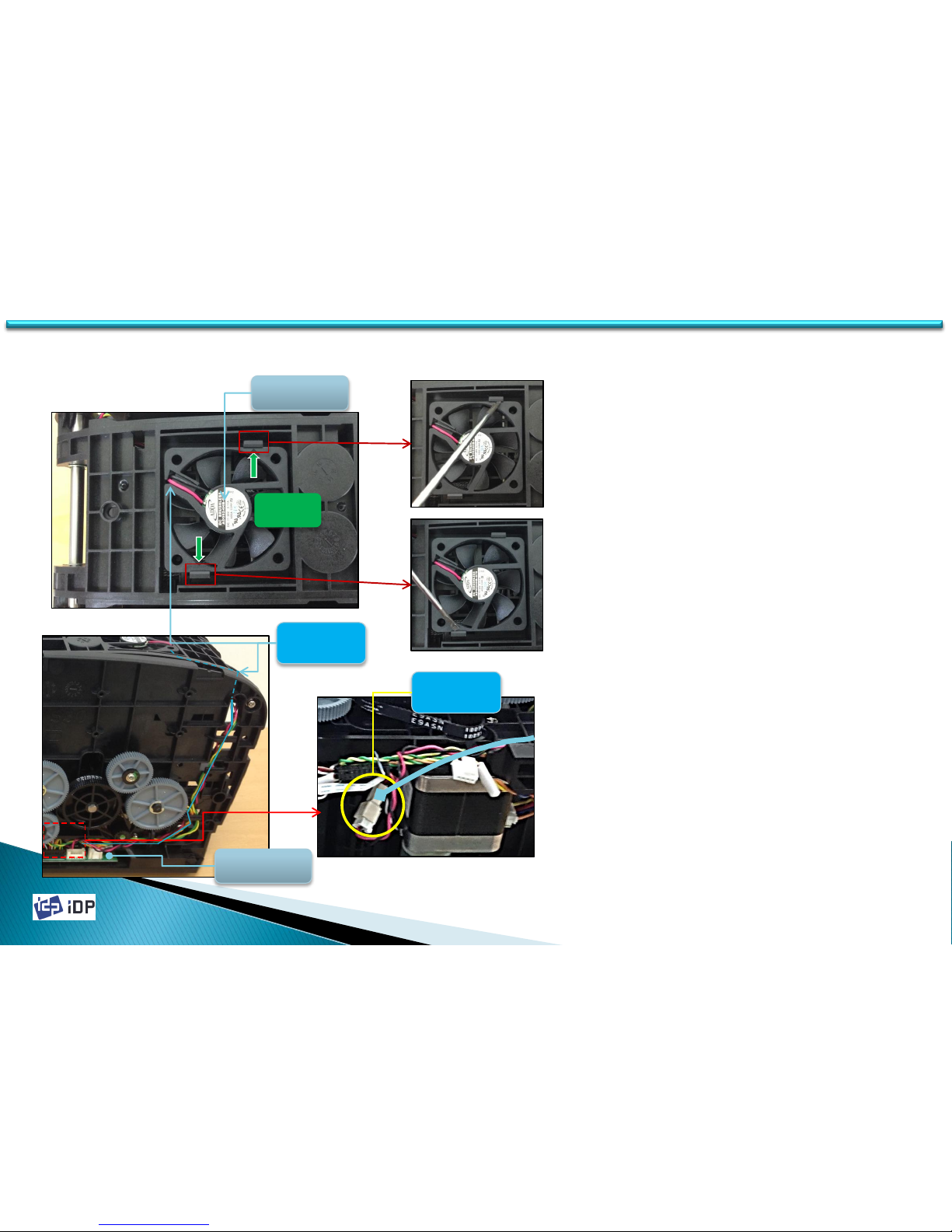
1. Cooling Fan is fixed on Top Cover Frame
by 2 Hooks.
2. Unlock Hooks using screw drive and
disassemble Cooling Fan.
3. Fan Wire is connected to Connector of
Main Board through inside of Printer.
4. Disassemble Bottom Frame from Printer
and disconnect Fan Wire from Connector.
5. Arrange Fan Wire and disconnect. Be
cautious not to peel it by Plate edge.
3.2.3 Cooling Fan
3.2 Top Cover Unit
FAN wire
M / B
Cooling FAN
FAN wire
Connector
Hook
Page 37
2014-03-24
37
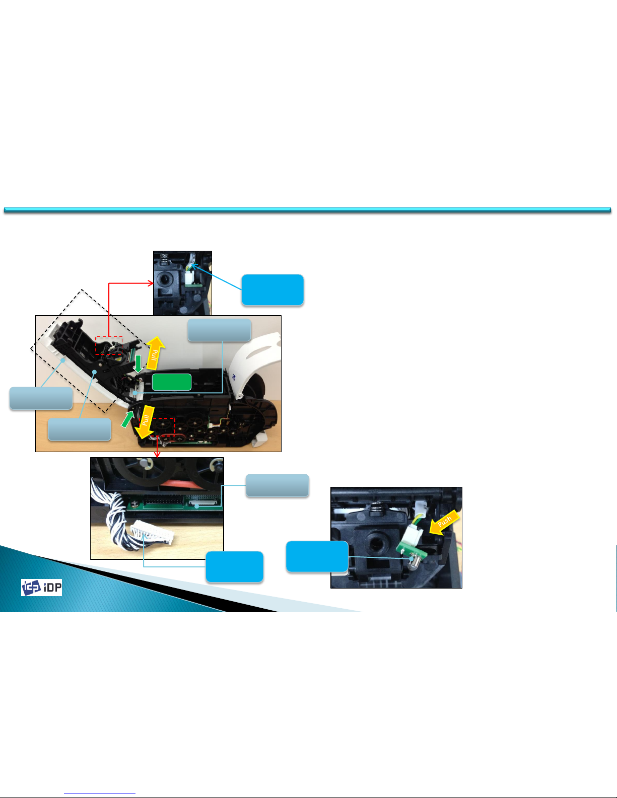
1. Top Cover Frame is assembled to Main
Frame by Shaft Top Set.
2. Disconnect Thermal Print Head Wire on
Main Board.
3. Disconnect Color In Sensor Wire on
Thermal Print Head position.
4. Loosen 2 screws and broaden both Main
Frames, and then disassemble Top Cover
Frame.
5. To disassemble Color in Sensor, push
Snap for fixing and pull out Color In
Sensor.
3.2.4 Top Cover Frame
3.2 Top Cover Unit
Thermal
Head wire
M / B
Top Cover
Top Cover
Mold
Screw
Shaft Top
Set
Color
Sensor wire
Color
Sensor wire
Page 38
2014-03-24
38
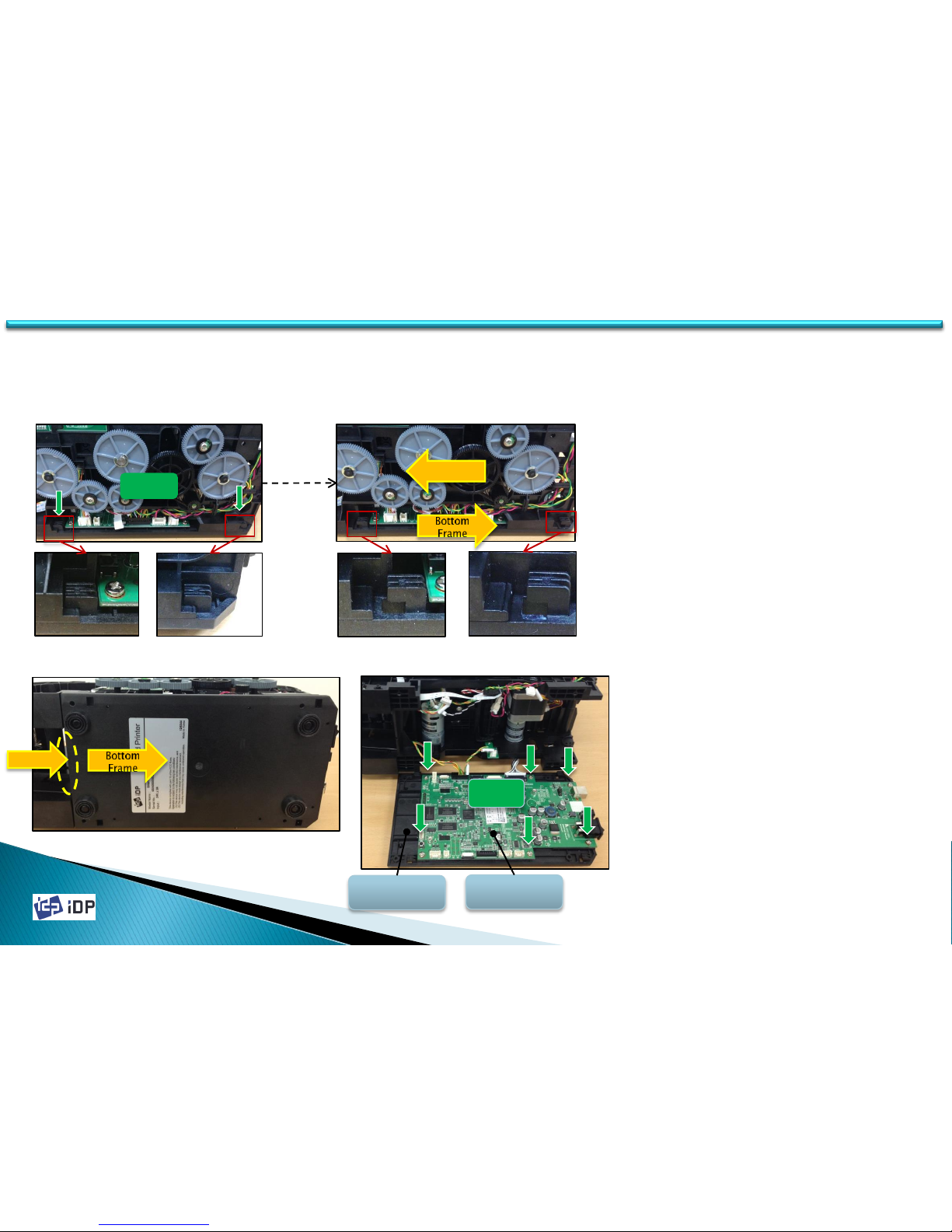
1. Main Board is fixed on Bottom Frame.
2. Bottom Frame is fixed on Main Frame by
4 Hooks and 4 Screws, but 4 screws are
loosened when Side Cover was
disassembled. (Refer to 3.1.1).
3. 2 Hooks are at same position on each
side (Lift and Right) on Bottom Frame.
4. To unlock Hooke, push Main Frame to
the right and push Bottom Frame to the
left.
5. More easy way to unlock Hooks, hold
Main Frame and push Bottom Frame to
the back side.
6. Main Board is fixed on Main Frame by 6
Screws.
3.3 Main PCBs
3.3.1 Main Board
M / B
Base Plate
Screw
3.3 Main PCBs
Hook
Push
Main
Frame
Page 39
2014-03-24
39
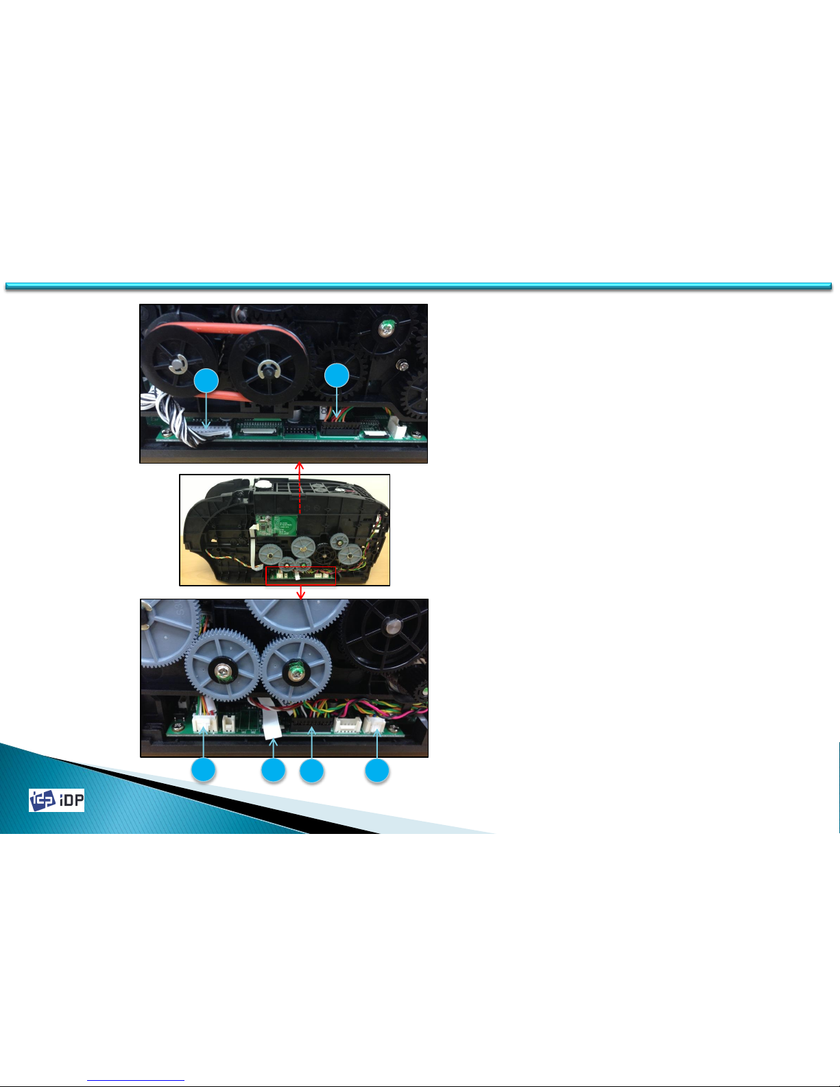
1. Before disassembling Main Board,
disconnect cables(T2, T3, T4, T5) on the
Right side.
( Be cautious not to make damage on T4
FFC)
2. T5 Wire is connected to LCD-Button unit.
On 3.1.2, when disassembling LCD-
Button unit, T5 was disconnected form
LCD-Button unit, but disconnect T5 Wire
to disassemble Main Board.
3. Disconnect cables(T1, T6) on the Left side.
Left View
Right View
T1
T3
T2
T4
T5
T6
3.3 Main PCBs
Page 40
2014-03-24
40
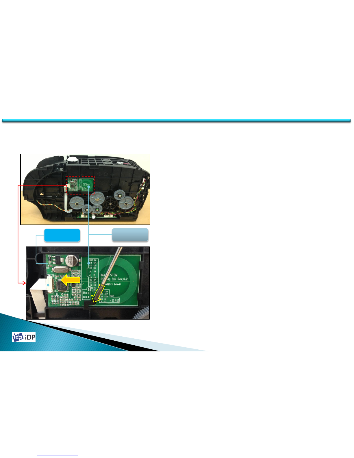
1. PCB Ribbon RF is fixed by Hook.
2. Disconnect FFC Wire from PCB Ribbon RF
(Be cautious no to make damage on FFC
connector)
3. Lift Hook parts by using the screw driver
or other device and pull out paralleled to
Side Frame direction to disassemble.
3.3.2 PCB Ribbon RF
PCB
Ribbon RF
Pull
FFC wire
3.3 Main PCBs
Page 41
2014-03-24
41
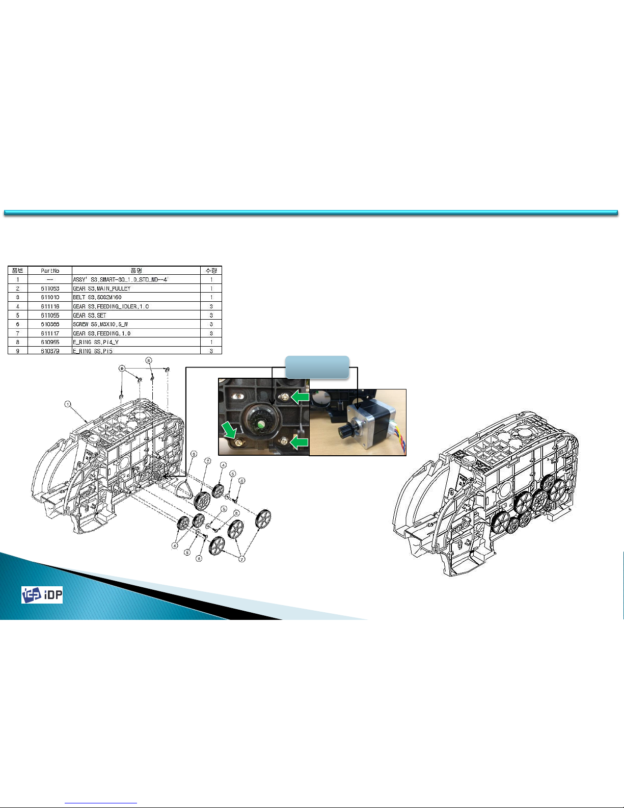
1. Main Drive consists of Step Motor and Time
Belt.
2. Disassemble Pulley(2), Time Belt(3) and
GEAR(7), and then can loosen 3 screws for
fixing Step Motor.
3. Step Motor is located inside of Frame.
4. When assemble Step Motor, adjusting the
tension by assembling Pulley(2) and Time
Belt(3) together and tighten 3 screws.
3.4 Drive Unit
3.4.1 Main Drive
3.4 Drive Unit
Main Drive
Motor
Page 42
2014-03-24
42
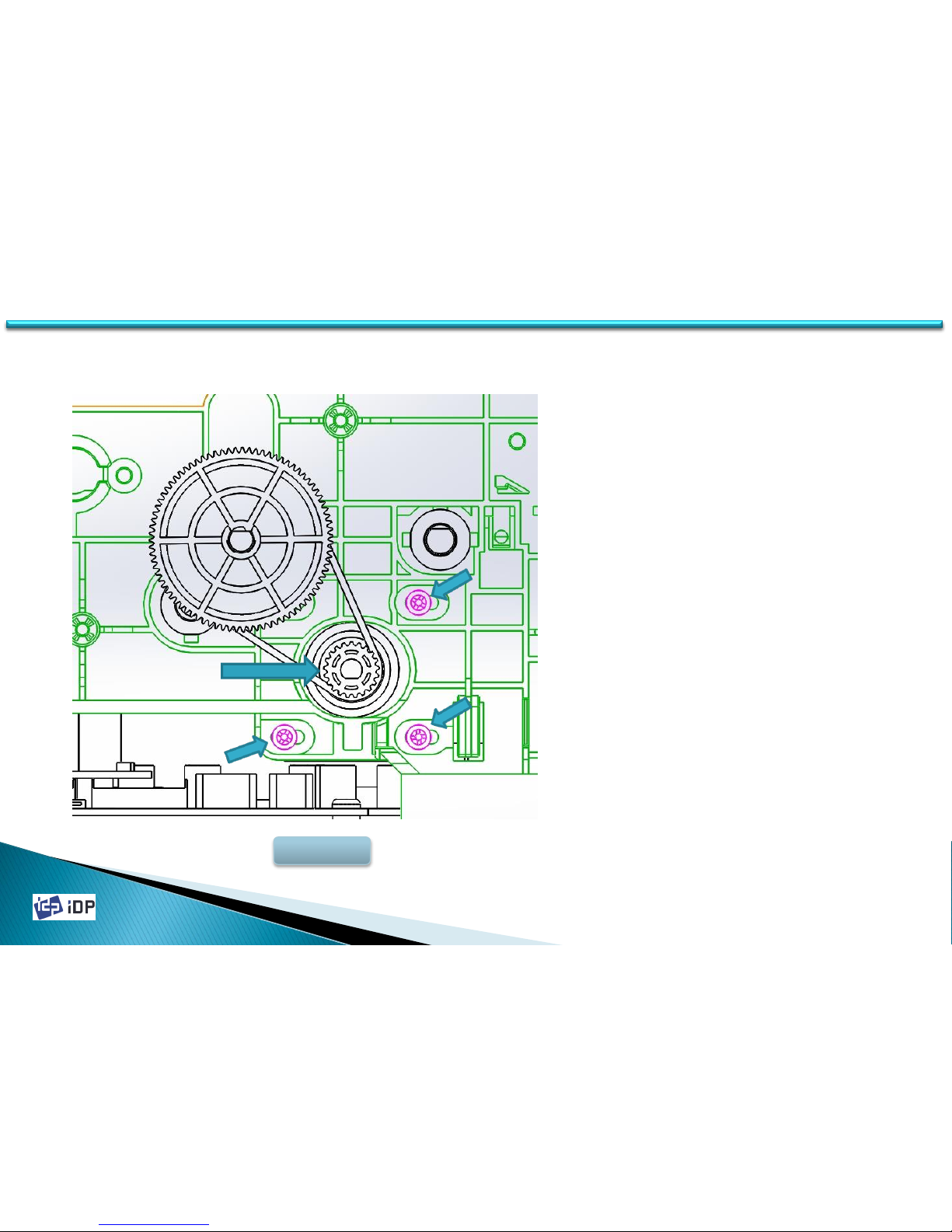
1. Belt-Step Motor 50M2M160 Tension
Setting
- After put the belt to the pulley, press
the pulley as 1.5 ~ 2 kgf to the No.1
arrow direction as Fig.3-1.
- In this state, tighten 3 screws to set
tension and fix Step Motor.
3.4.2 BELT Tension Setting
3.3 Drive Unit
42
Fig,3-1
1
2
2
2
Page 43
2014-03-24
43
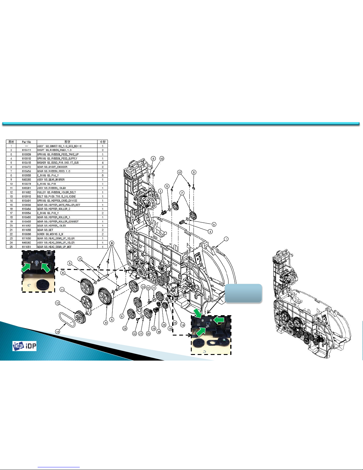
1. Ribbon and Head Down_Up Drive is located
on the left side of Frame.
2 Ribbon Motor is fixed by 2 screws inside of
Frame. (See B.2.1 ASSY S3,LEFT-1, B2.2 ASSY
S3,LEFT-2)
3 After disassembling Gear is assembled to
Ribbon Motor, enable to disassemble Ribbon
Motor.
4 Head Up/Down Motor is fixed by 3 screws
inside of Frame. (See B.2.1 ASSY S3,LEFT-1,
B2.2 ASSY S3,LEFT-2)
5 After disassembling Gear(25) and ASSY(24),
enable to disassemble Head Up/Down Motor.
6 After loosening 3 screws and disconnecting
wire, enable to disassemble Head Up/Down
Motor.
3.4.3 Ribbon, Head Down_Up Drive
Head
Up/Down
Motor
43
3.4 Drive Unit
Page 44
2014-03-24
44
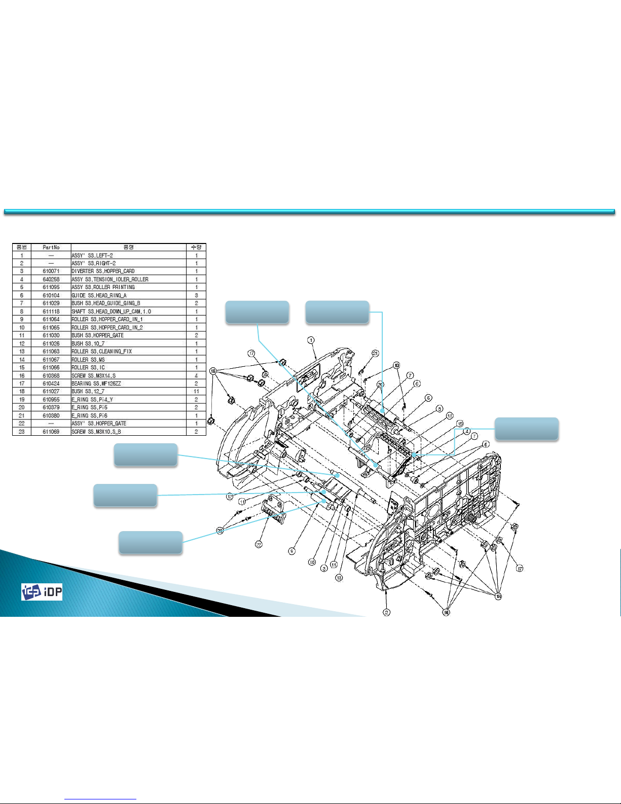
1. Every Roller is fixed by using Bearing or
Bushing on each Main Frame.
2. Disassemble E-Ring on the end of Roller.
3. Disassemble Bearing or Bushing fixed on
Frame. While pushing Roller to Frame
Right Side. Disassemble Left Side of
Roller from Frame.
3.5 Rollers
3.6 Rollers
Cleaning
Roller Fixed
Card In
Roller2
Ms Roller
IC Roller
Printing
Roller
44
Card In
Roller1
Page 45
2014-03-24
45
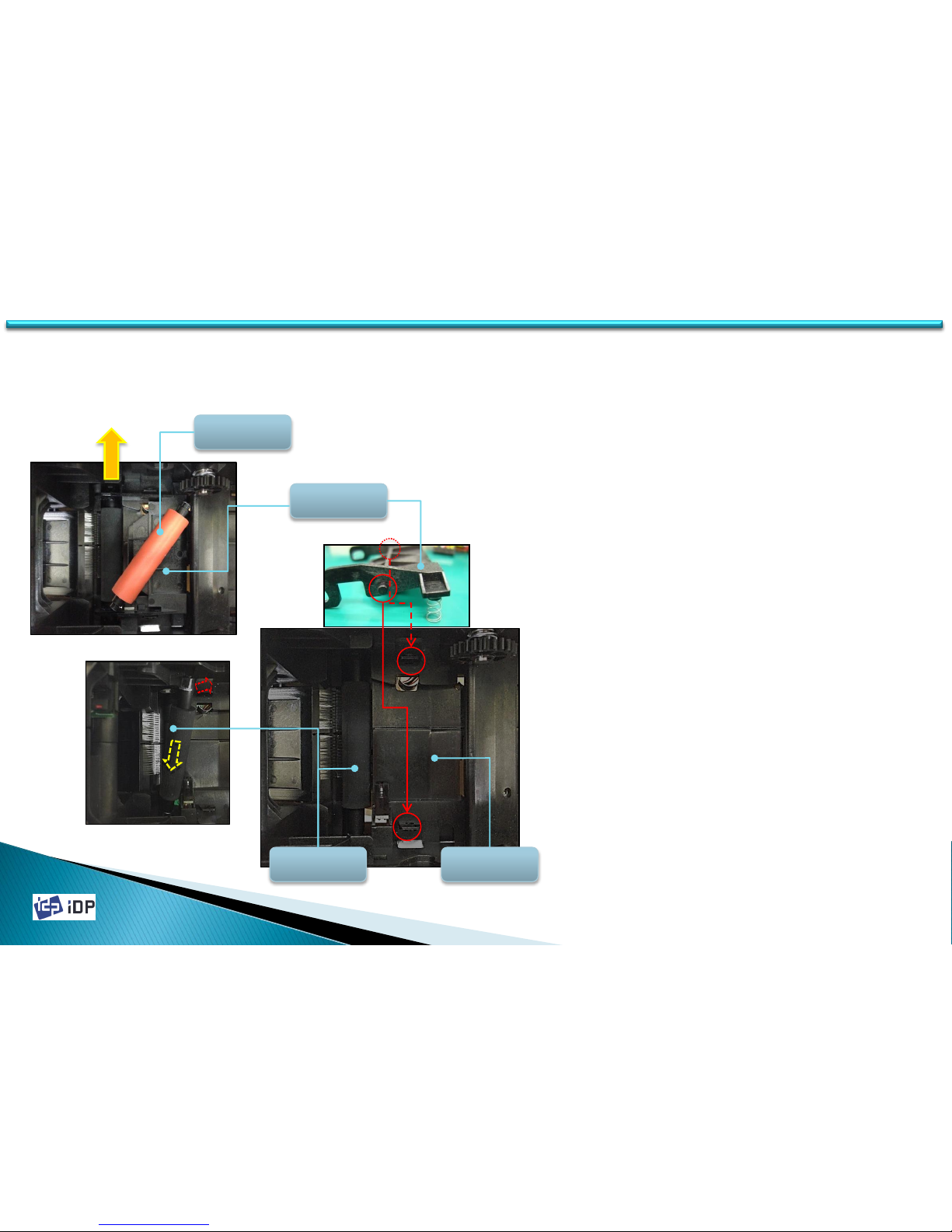
1. While broadening the fixing parts of
Cleaning Roller Bracket, pull out Cleaning
Roller.
2. Cleaning Roller Bracket is assembled to
Main Frame by using Hinge.
3. Transform the fixing parts of Main Frame
for Hinge and disassemble Cleaning
Bracket.
4. Disassemble Bush on the end of Cleaning
Roller Fixed.
5. While pushing Cleaning Roller Fixed to
the Right Side, disassemble Roller from
the Left Side.
3.5.1 Cleaning Roller / Cleaning Roller Fixed
3.6 Rollers
Cleaning
Roller
Cleaning
Roller Fixed
Cleaning
Roller BKT
Main Frame
Pull
Page 46
2014-03-24
4.1 Setup
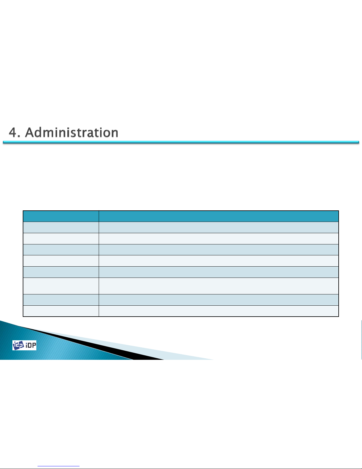
Item Explanation
Print Location Set the start position or end position of the printed image.
Print Thickness Set the print thickness of color, resin black, overlay.
Ribbon Operation Set the ribbon moving power
Flipper Set the rotation angle of Flipper
Magnetic Stripe Set the start position of magnetic data.
Ribbon Color Sensor
Recognition
Set the sensor value to distinguish the ribbon color.
Security Set the value for the printer security
Etc. Set the printer’s hardware version and the printer state.
4.1 Setup
4.1.1 Overview
4.1.1.1 Function
SMART Card Printer is delivered in optimized state from factory. However it can be set the setup value using
CardPrinterSetup Utility provided with CD when the unit is disassemble and reassemble or change of part. The
following setup value can be changed using CardPrinterSetup utility.
46
Page 47
2014-03-24
47
4.1.1.2 Start
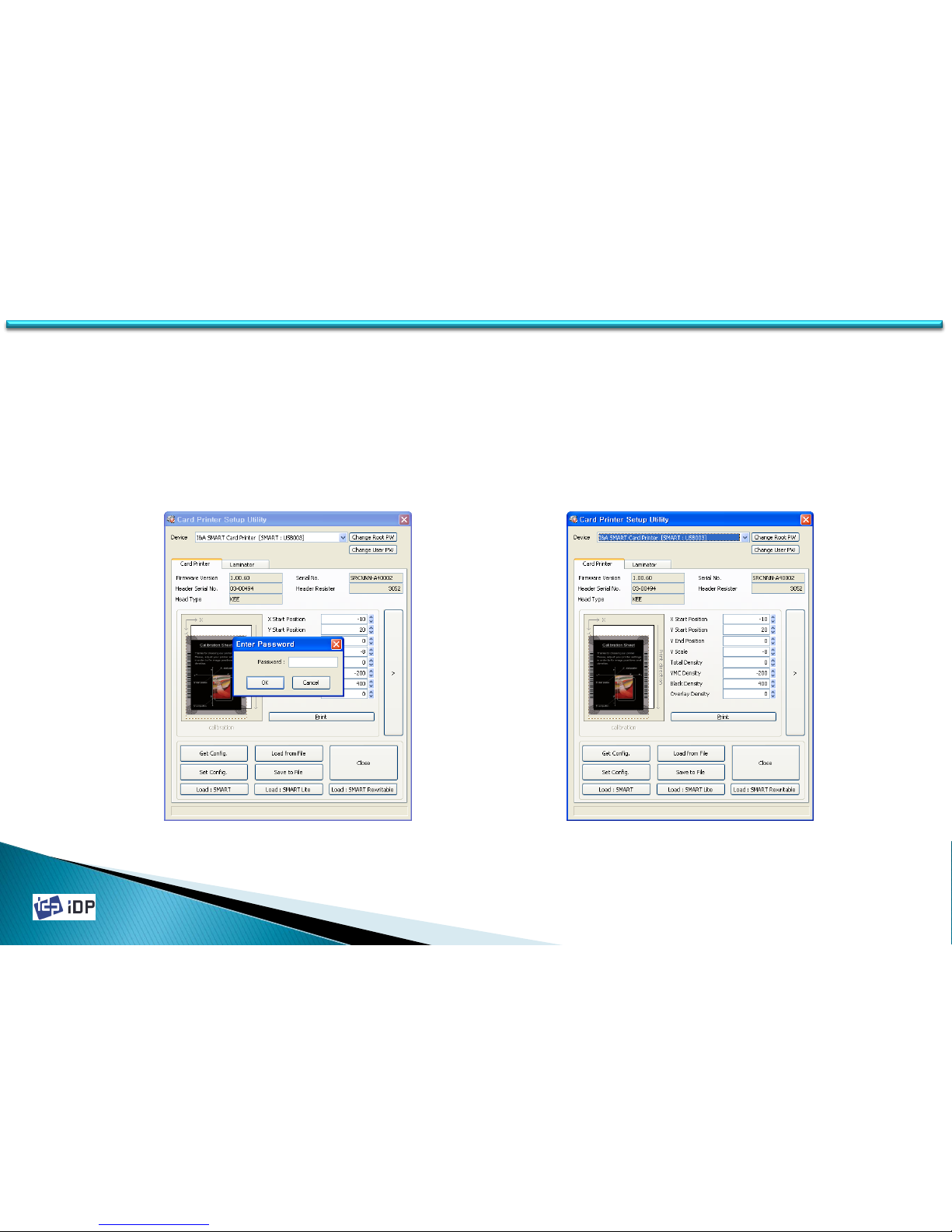
When start the program there will be displayed the password input window. If input the password, the recorded setup
value will be shown and can change that value. The password is saved to SMART Card Printer so even if change to
other PC, it need to input the password to change the setup value.
(SMART Printer is not set its password so if you press O.K, you can see the setup value and can change. Default is no
password)
[ CardPrinterSetup startup ]
[ CardPrinterSetup main window ]
4.1 Setup
Page 48
2014-03-24
48
4.1.2 Setup
4.1.2.1 Basic Setup
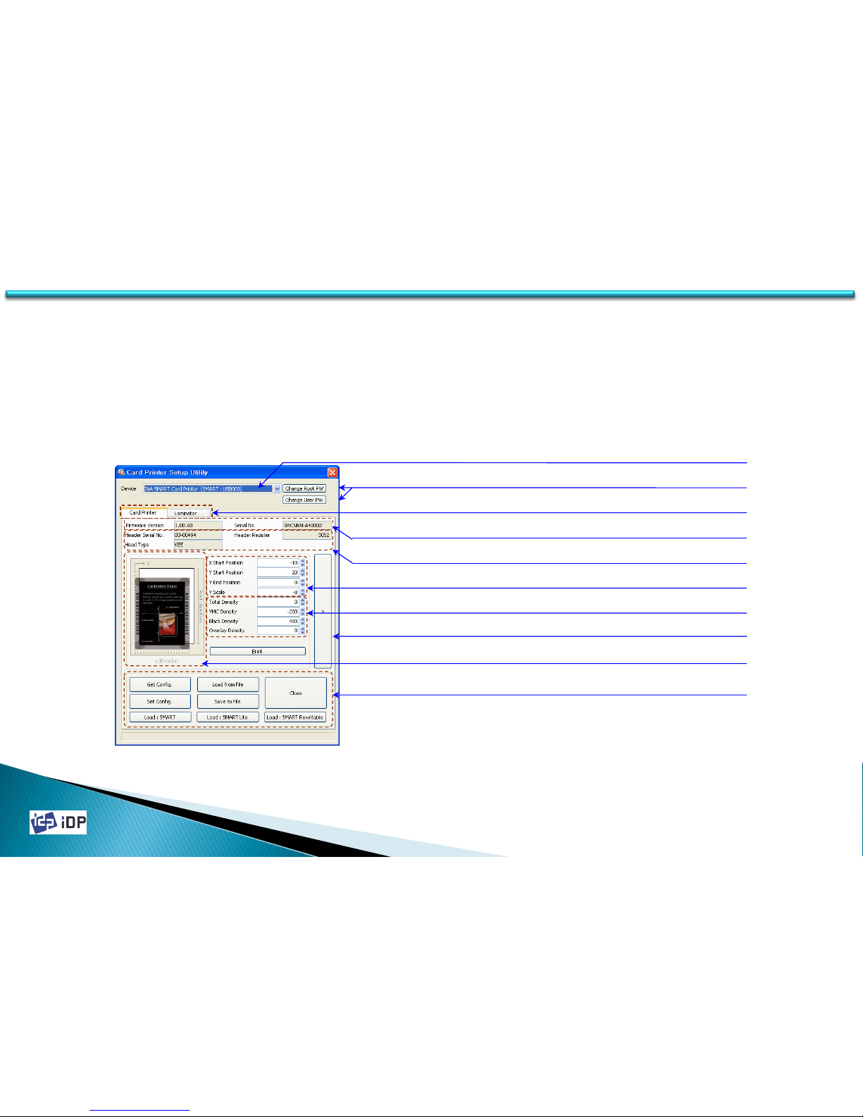
The most of basic setup can be realized on this window easily. To set more detailed setup, press “>” button for
expansion.
4.1 Setup
Printer ID | Printer Name
Change Root/User password for SMART Printer
Printer information ( Firmware Version, Serial Number)
Thermal header information
Image position related factors
Image density related factors
Expansion button for extended setup
Calibration sheet preview and printing
Main menus for get/set, save/load, close and load default
Device selection tab
Page 49
2014-03-24
49
4.1 Setup
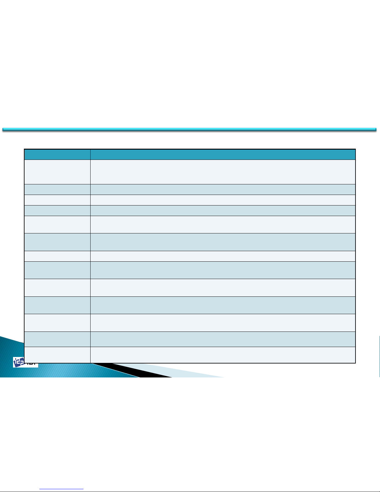
Item Explanation
Device
Available device list will be displayed. “SMART” is printer ID value. “I&A SMART Card Printer”
is the printer driver name. Using the printer ID, the printer can be distinguish when you
use SDK.
Change Password Change password
Firmware Ver. The printer’s firmware version
Serial No. The printer’s serial no.
Header Serial No.
The printer’s Thermal Print Head serial no. When the thermal print head is change, it
should be changed.(See 4.1.3.6)
Header Resister
The resistor value of the thermal print head. When the thermal print head is change, it
should be changed.
Head Type Set type of thermal print head.
X Start Position
Adjust X start position (Range : -30 ~ 30)
※ If the value is change, the example will be changed. (See 4.1.3.1)
Y Start Position
Adjust Y start position. (Range : -30 ~ 30)
※ If the value is change, the example will be changed. (See 4.1.3.1)
Y End Position
Adjust Y end position (Range : -20 ~ 20)
※ If the value is change, the example will be changed. (See 4.1.3.1)
Y Scale
Adjust the length of image (Range : -60 ~ 60)
※ If the value is change, the example will be changed. (See 4.1.3.1)
Total Density Set the image’s total density (Range : -500 ~ 500) (See 4.1.3.2)
YMC Density Set the color density (YMC) (Range : -500 ~ 500) (See 4.1.3.2)
• Basic Setup Item
Page 50
2014-03-24
50
4.1 Setup
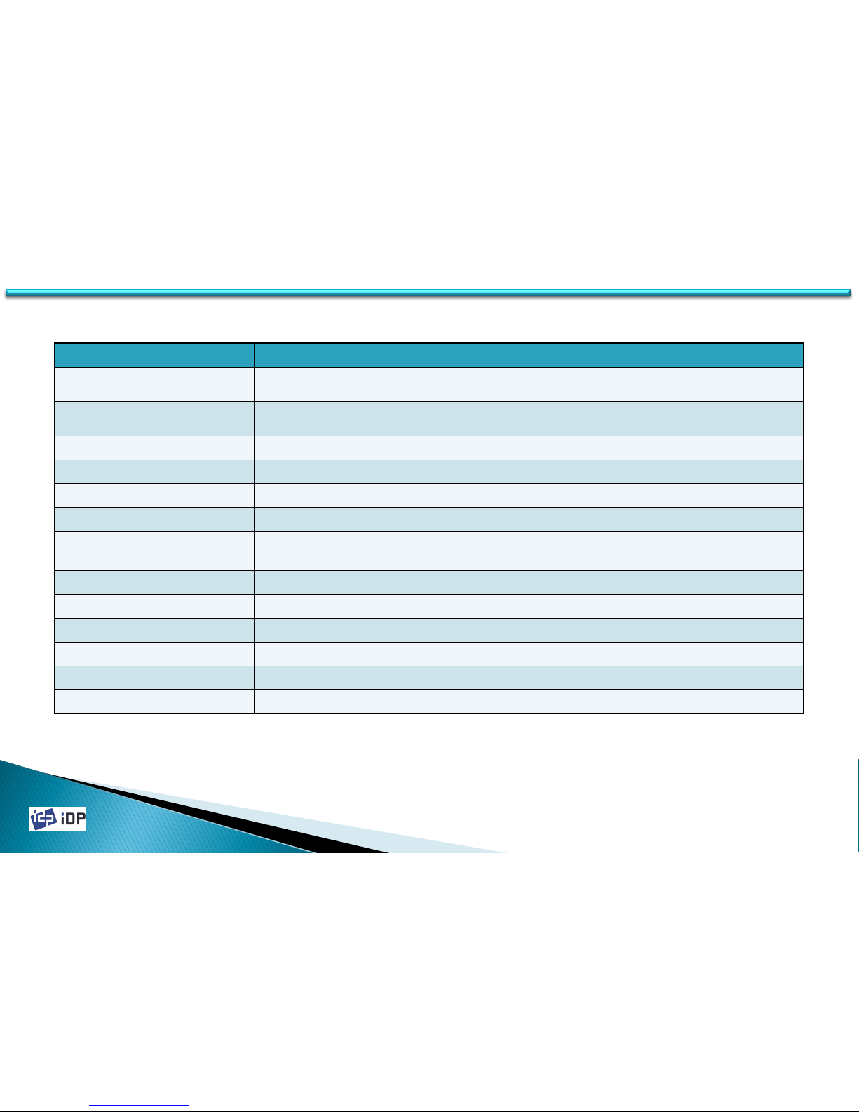
Item Explanation
Black Density Set the image’s total density (Range : -1500 ~ 1000) (See 4.1.3.2)
Overlay Density Set the color density (YMC) (Range : -500 ~ 500) (See 4.1.3.2)
Example Preview the changed value
Print To check the adjusted value. You can print the test card
> Show the expansion items
Get Config. Load the printer’s setup value
Set Config.
Save the changed setup value
In case you use the password, if it is not matching, it will not be saved
Load from File Load the saved file
Save to File Save the setup value to the file
Close Exit the program
Load : SMART Load standard setup value for SMART
Load : SMART Lite Load standard setup value for SMART Lite
Load : SMART Rewritable Load standard setup value for SMART Rewritable
• Basic Setup Item
Page 51
2014-03-24
51
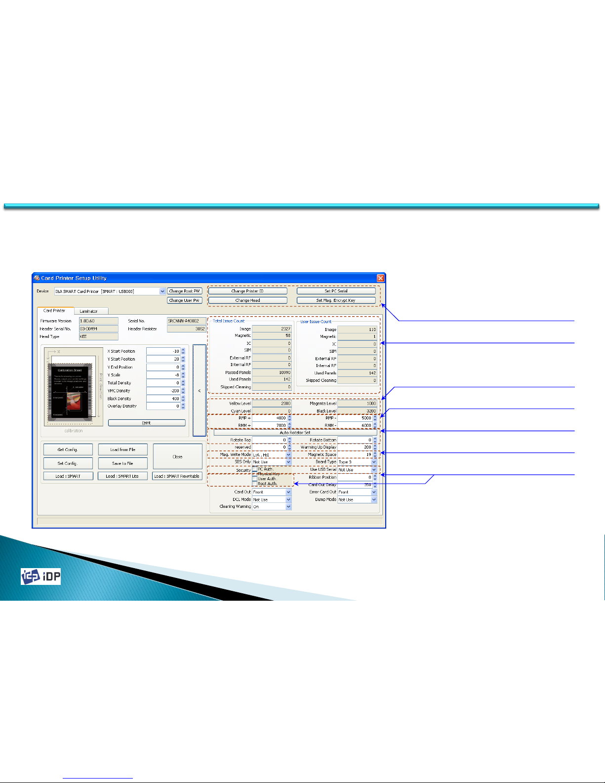
4.1.2.2 Expansion Setup
This window can be used to check the printer’s state or change the detailed setup.
4.1 Setup
Menu buttons
Usage counter
Ribbon motor control factors
Flipper control factors
Magnetic control factors
Ribbon sensor control factors
Security factors
Page 52
2014-03-24
52
4.1 Setup
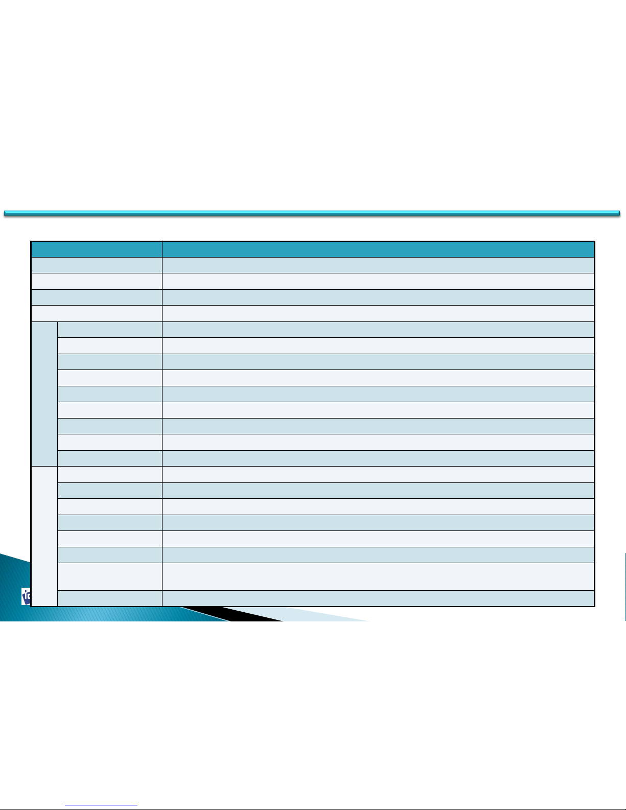
Item Explanation
Change Printer ID When use SDK, this ID can be used to distinguish each printer (See 4.1.3.8)
Set PC Serial When use PC Authentication, set the PC to print (See 4.1.3.7)
Change Head In case of changing thermal print head, set the serial no. and resistor value (See 4.1.3.6)
Set Mag. Encrypt Key When transport the magnetic data and if it is encrypted, you can set the Key (See 4.1.3.7)
T
o
t
a
l
I
s
s
u
e
Image Total printed image number
Magnetic Total magnetic encoding number
IC Total Contact Smartcard encoding number (It can be increasing by SDK)
SIM Total Contact Smartcard(SIM) encoding number (It can be increased by SDK)
External RF Total RF Smartcard(external) encoding number (It can be increased by SDK)
Internal RF Total RF Smartcard(internal) encoding number (It can be increased by SDK)
Printed Panels Printed panel number for the image printing
Cleaning Count Total printed panel number and magnetic encoding number for checking cleaning cycle.
Skipped Cleaning After demanding clean warning, skipped cleaning number
U
s
e
r
I
s
s
u
e
Image After installing new head, printed image number
Magnetic After installing new head, magnetic encoding number
IC After installing new head, Contact Smartcard encoding number (It can be increasing by SDK)
SIM After installing new head, SIM Smartcard encoding number (It can be increased by SDK)
External RF After installing new head, RF card(external) encoding number (It can be increased by SDK)
Internal RF After installing new head, RF card(internal) encoding number (It can be increased by SDK)
Cleaning Count
After installing new head, printed panel number and magnetic encoding number for
checking cleaning cycle.
Skipped Cleaning After installing new head and demanding clean warning, skipped cleaning number
• Expansion Setup Item
Page 53
2014-03-24
53
4.1 Setup
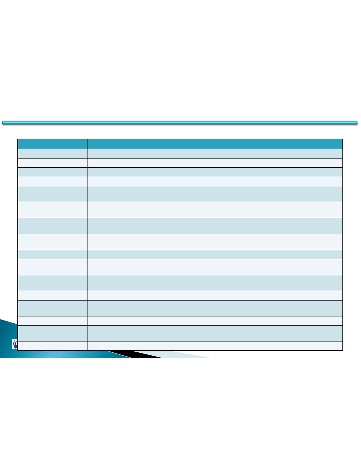
Item Explanation
Yellow Level Set the yellow level value (Use only in board type 1, 2 )
Magenta Level Set the magnetic level value (Use only in board type 1, 2)
Cyan Level Set the cyan level value (Use board type 1, 2)
Black Level Set the black level value (Use board type 1, 2)
RMP +
Set the ribbon motor’s max torque value when a panel of ribbon is being printed on a card
Range : 2000 ~ 7000 (See 4.1.3.3)
RMP -
Set the ribbon motor’s min torque value when a panel of ribbon is being printed on a card
Range : 2000 ~ 7000 (See 4.1.3.3)
RMM+
Set the ribbon motor’s max torque value when a panel of ribbon is not being printed (RMM+
should be bigger than RMM–) Range : 4000 ~ 8000 (See 4.1.3.3)
RMM-
Set the ribbon motor’s min torque value when a panel of ribbon is not being printed (RMM–
should be smaller than RMM+) Range : 4000 ~ 8000 (See 4.1.3.3)
Auto Rotator Set Automatically Find proper Rotate Top and Rotator Bottom value
Rotate Top
Set the angle to be flat for the Flipper front side (Range : -30 ~ 30)
(The lower the value the more the angle) (See 4.1.3.4)
Rotate Bottom
Set the angle to be flat for the Flipper back side (Range : -30 ~ 30)
(The lower the value the more the angle) (See 4.1.3.4)
Reserved Not Use
Warming Up Display
Set the cycle of blinking LED button when heat the head on RW model. If the value is
increased, the LED blink slower.
Mag. Write Mode Set the track writing mode
Magnetic Space
Set the start position of magnetic data (Range : 10 ~ 30)
If the value is increased, the start position will be close to the end (See 4.1.3.5)
SBS Only Set the printer is only operated in the application which made by SDK (See 4.1.3.7)
• Expansion Setup Item
Page 54
2014-03-24
54
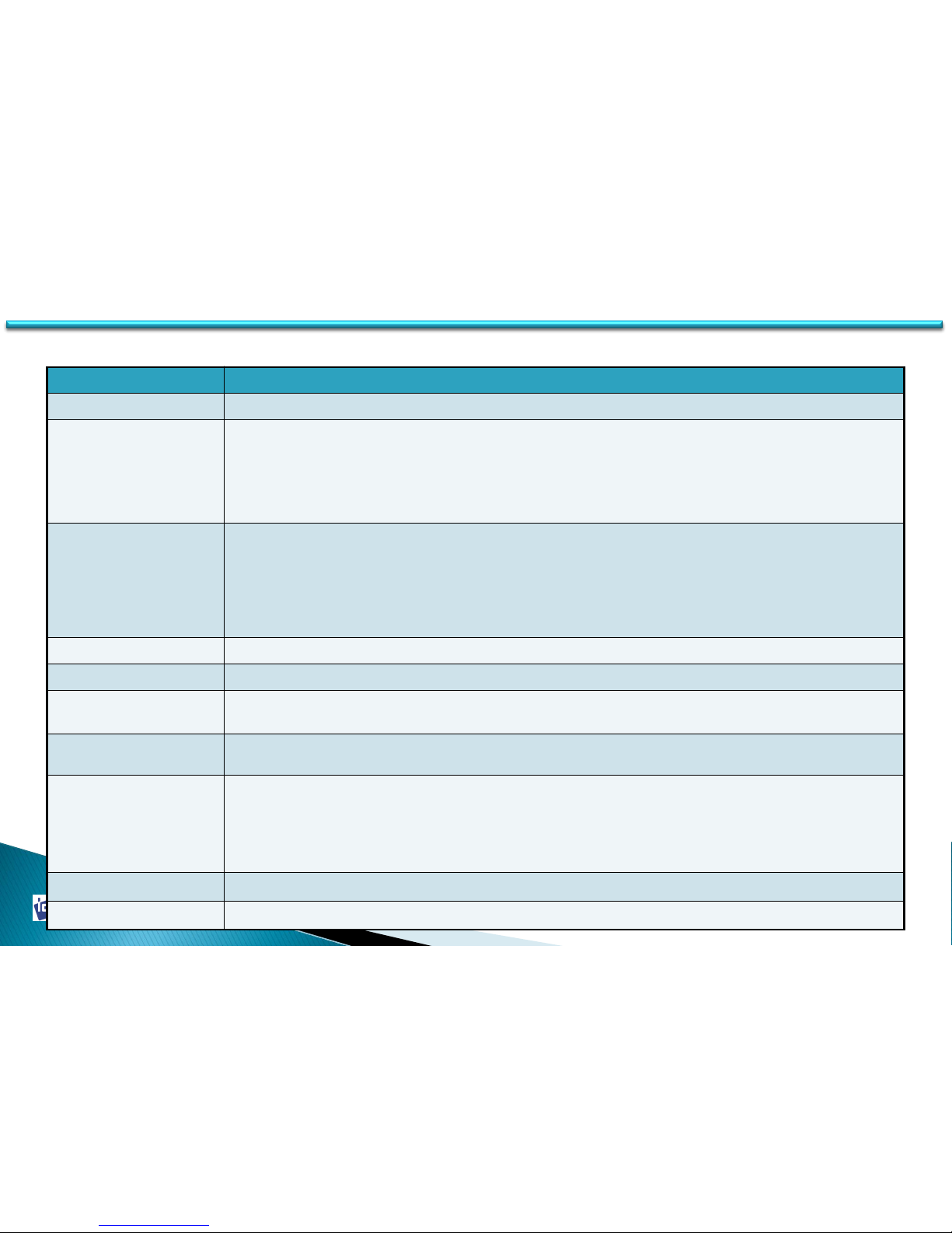
Item Explanation
Board type
Set the main board type (Do not change!)
Security
Authentication function is applied for security in SMART printer. (See 4.1.3.7)
- PC Auth. : Matching SMART printer and PC ( To use this function, press “Set PC Serial” and save the
PC authentication information to SMART Printer)
- Physical key : Set the use of Physical Key in case the printer have customized physical key
- User Auth. : Set password for specified user.
- Root Auth. : Set password for administrator.
Use USB Serial
When SMART is connected to USB, it transmits the USB serial number to PC. Default is the
same number used by all SMART. Please set this option when you want to use multiple
SMART printers connected to 1 PC via USB. It enables unique serial numbers for each USB.
(See 4.1.3.8)
When you want to use multiple SMART printers connected to 1 PC via USB, you have to set
this option of SMART one at a time and connect all SMARTs to PC via USB.
Ribbon Position Option for ribbon printing reposition. It can be adjusted between +5 ~ -5 (mm).
Card Out Delay Set the time to operate Hopper Motor. Do not change.
Card Out
Set printed or encoded card out direction (The back out can be done only in dual side
printer)
Error Card Out Set error card out direction (The back out can be done only in dual side printer)
DCL Mode
Use DCL mode. If set DCL mode, the driver installation will not be required when connect the
printer. Even if the driver is installed, it does not use the driver. Please note it is developed
for the user who want to operate the printer with their specific program because do not need
to use the driver. (Note: When use this function, it is not printing in normal program.)
(See 4.1.3.8)
Dump Mode Set to record the log data in printer.
Cleaning Warning Set to activate cleaning warning window. (See 4.1.3.8)
• Expansion Setup Item
Page 55
2014-03-24
55
4.1.3 Printer Setup Adjustment
4.1.3.1 Printing Location
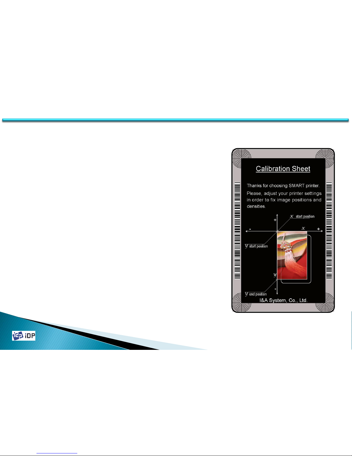
SMART Card Printer is the direct thermal printer and need to some
setting to print all over the card surface.
In CardPrinterSetup, if press “Print” button, the image like left side will
be printed. In this time, if four circles on each side are printed well
and the space of upper & bottom is in 0.5mm, it is proper setting.
For correct setting, you can adjust the setup value as follows.
1. Do not make too much space on left and right side as adjusting X
start position value.
2. Do make the image start point in 0.4mm ~ 0.5mm from the card
upper side as adjusting Y start position value.
3. Do make the image end point in 0.4mm ~ 0.5mm from the card
bottom side as adjusting Y end position value. In this case, Y scale
value should be input more bigger than the proper setup value.
4. Do make the four circles can be shown fully as adjusting Y scale value.
4.1 Setup
Page 56
2014-03-24
56
4.1.3.2 Printing Density
SMART Card Printer is direct thermal printer. Use the thermal heat to print. To print the correct and proper
printing, the thermal heat should be different in color printing, resin black printing, overlay printing. So for the
best printing image, some adjustment is needed.
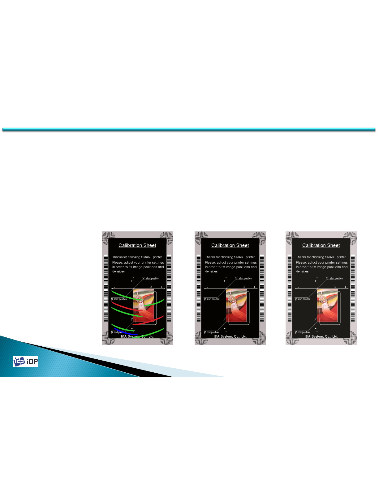
• Color Printing Density
Color printing is print the color image using the color ribbon. SMART printer can print 16,777,216 color. In its
color printing thickness, the color expression range can be widen and get the clear image by printing so thickly
as possible as the ribbon is allowed. However if it is too thick, the ribbon can folded and there might be green or
red bad image. And if it is too weak, the image is not clear as below third figure. Set the proper thickness.
Too Strong Proper Too Weak
4.1 Setup
Page 57
2014-03-24
57
• Resin Black Printing Density
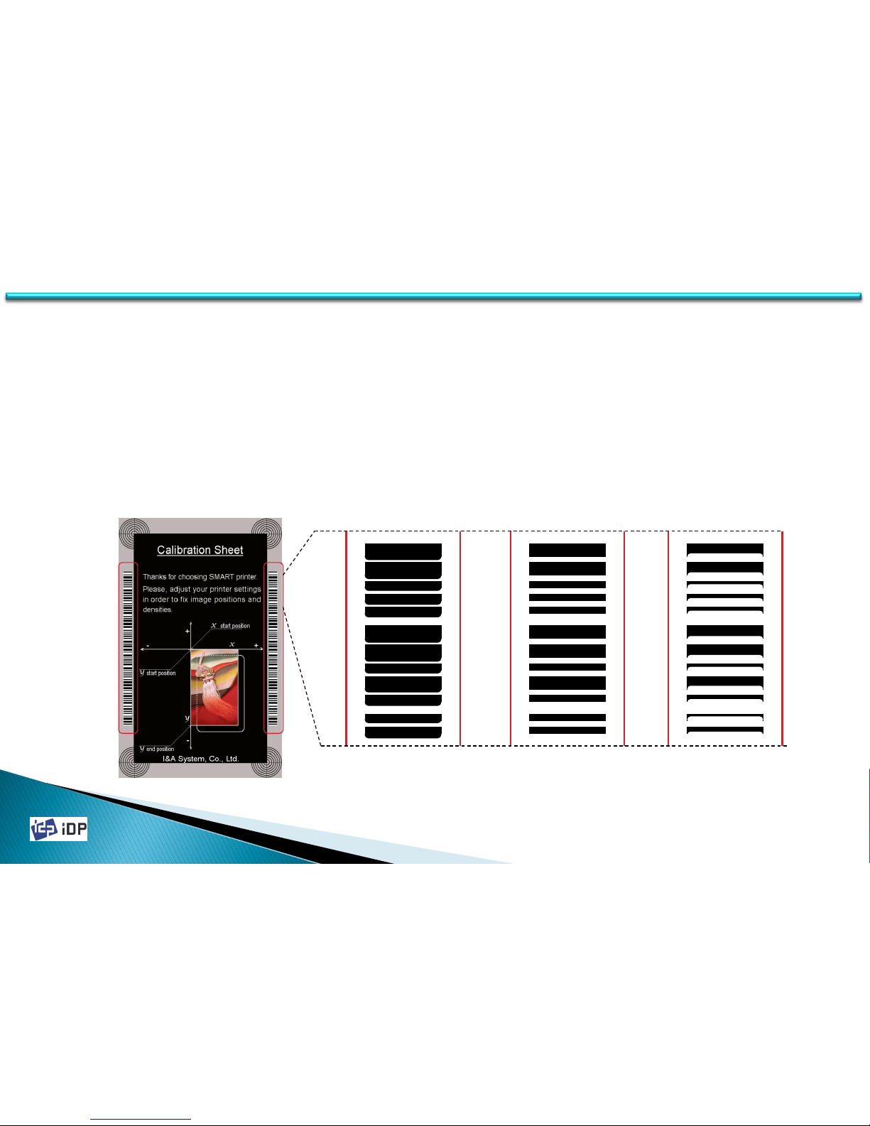
Resin Black is used to print the black clearly such as the barcode or text. It print the black which extracted by
the printer device driver or set as black in Smart Design. The red box in the below figure is printed by resin
black.
Resin Black is printed as binary type, not level for the printing result. So the setting standard of printing
thickness is different.
If the thickness is too strong, the barcode is not clear and too widen. And if too weak, the barcode is printed
too short. Set the resin black printing thickness properly to get the clear barcode printing. Not too strong but
a little bit strong is best.
Too Strong Proper Too Weak
4.1 Setup
Page 58
2014-03-24
58
• Overlay Printing Thickness
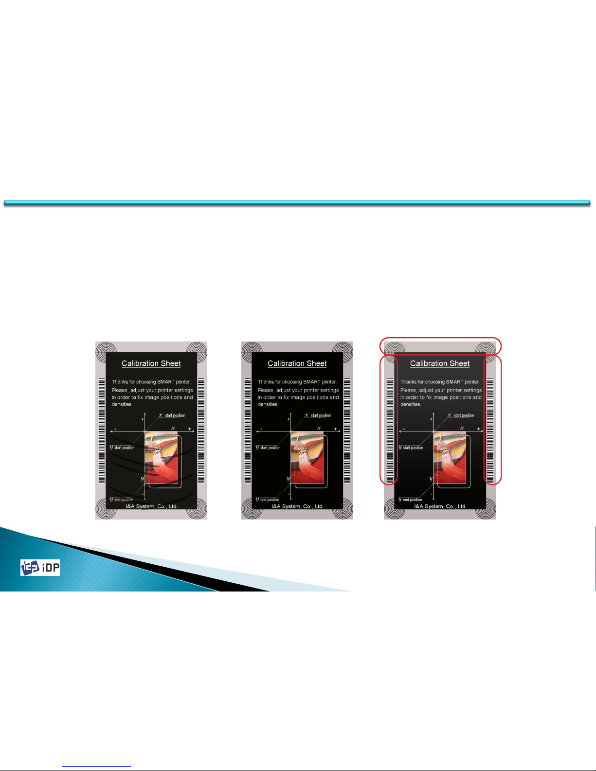
Overlay is coating to the surface of card for the protection of printing image. Usually the overlay print all over
the card surface but it can be printed in specific area by the device driver or Smart Design software.
Overlay is binary type such as black resin, print or not. So the setting standard of printing thickness is different.
If it is too strong, it is too dull and can be occurred the bad overly such as left figure. And if too weak, some
area will not be overlaid. You can check it if place the card under light. So set the overlay printing thickness
properly. Not too strong but a little bit strong is best.
Too Strong Proper Too Weak
4.1 Setup
Page 59
2014-03-24
59
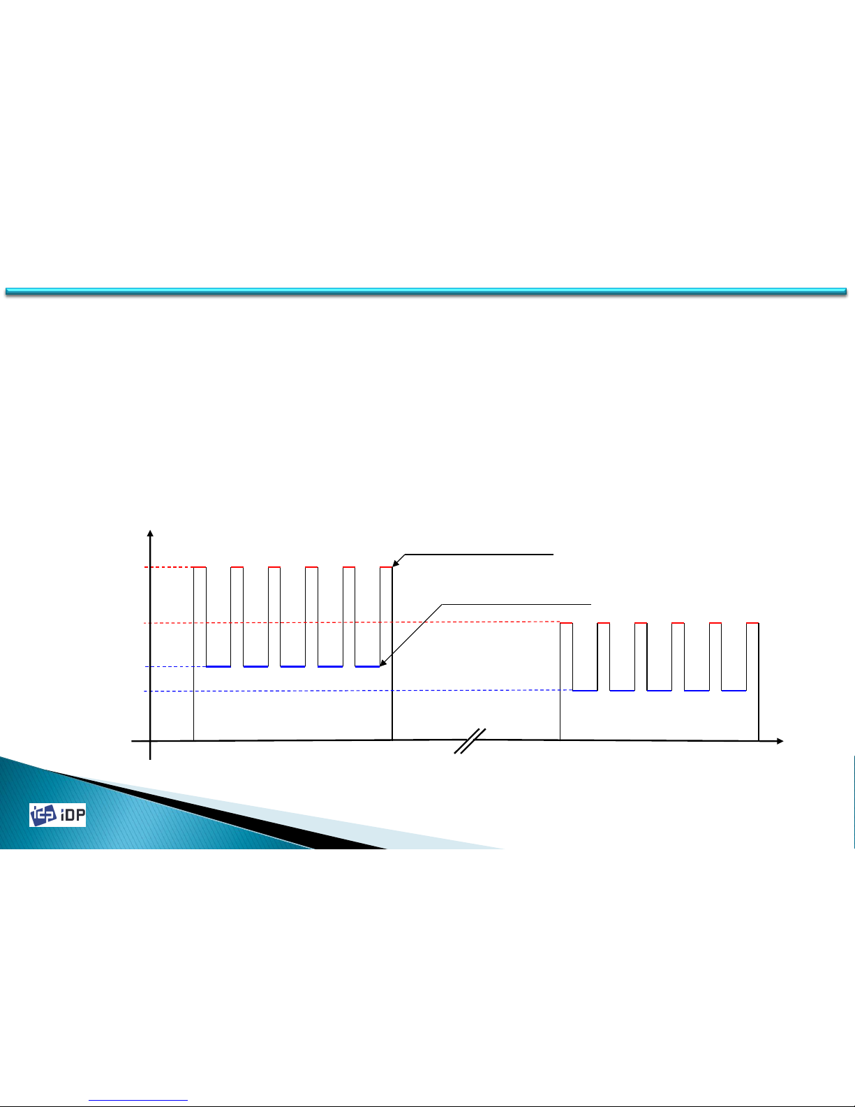
4.1.3.3 Ribbon Operation
SMART-30 Card Printer’s ribbon movement is variable to make the interference minimized. So to get the stable
image quality, set the proper ribbon movement setting. As below graph SMART Card Printer is control the speed of
printing and normal movement differently to get the regular speed. And its movement speed is changed for the
remained ribbon balance. Set the movement speed as below graph.
RMP control the ribbon movement when printing. If set too low, the ribbon can not be rewind and the problem can be
occurred. On the contrary if set too strong, the rolling speed is too fast so there might be bad image.
RMM control the normal movement. If set too low value, the printer is stop as print head is adhered with ribbon. If
too high, the ribbon rolling speed is too fast so the correct printing position can not be detected.
(We recommend to not change RMP and RMM until there is critical problem)
250 Ribbon Balance 1
RMP +
RMP -
RMM +
RMM -
Movement Speed
Normal Ribbon Movement
Printing Ribbon Movement
4.1 Setup
Page 60
2014-03-24
60
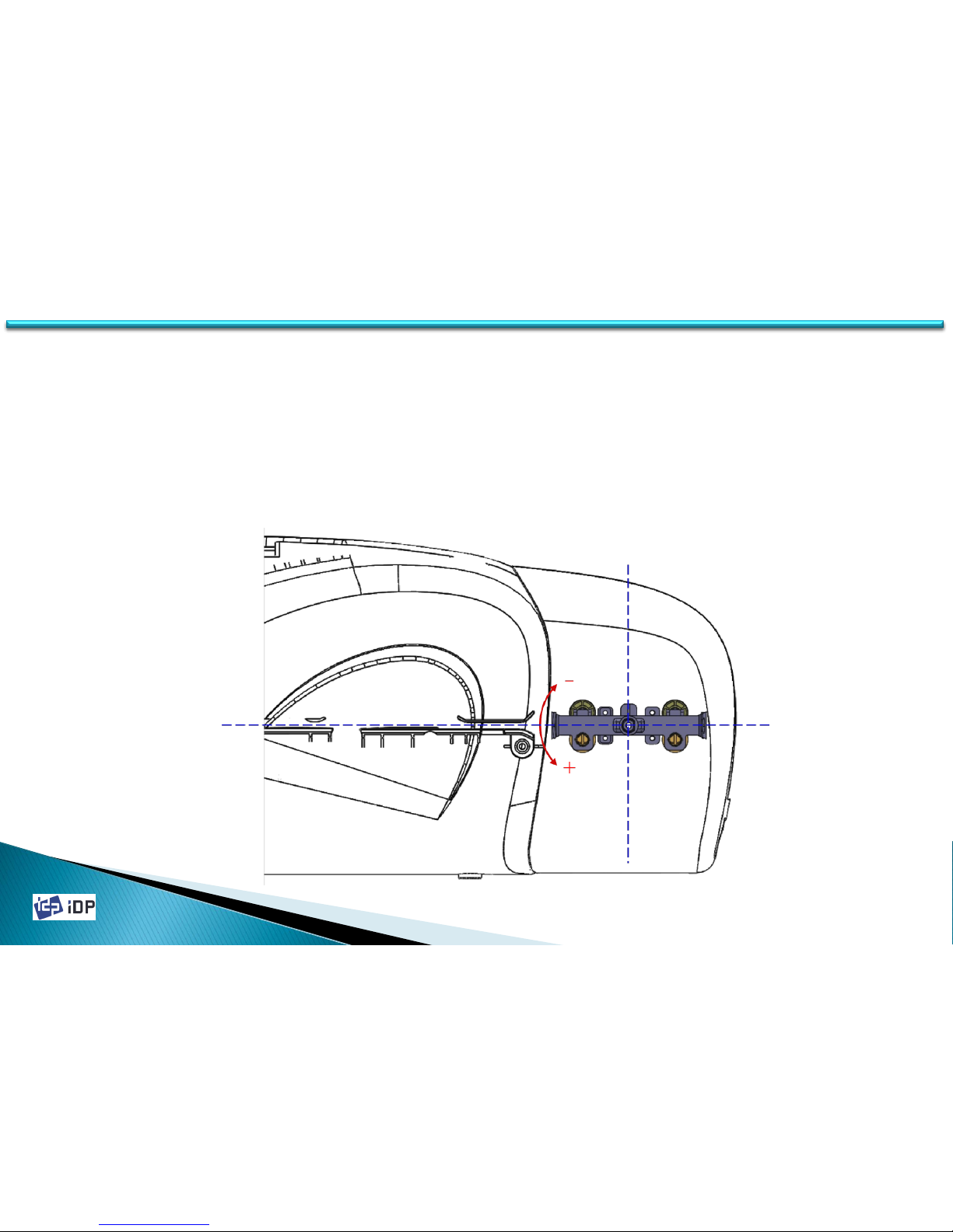
4.1.3.4 Flipper
On SMART-30, flipper can be attached as option. When there is no printing, the Flipper keep the horizontal flat. So
the setup of Flipper is to make it the horizontal flat by adjusting its angle.
“Rotate Top” and “Rotate Bottom” are the accurate setting when the Flipper is front side or back side to make a
horizontal flat with the card movement passage. This value is between -30 ~ 30 and + is upper adjustment, - is
down adjustment.
(We recommend that there is Flipper card jam problem.)
4.1 Setup
Page 61
2014-03-24
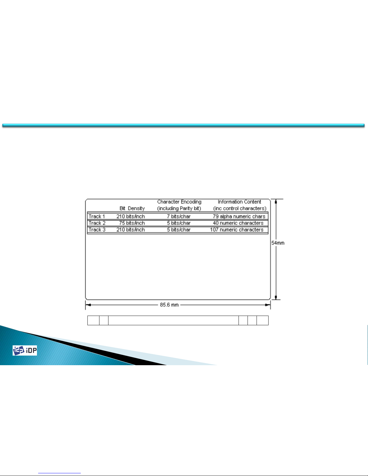
SC SS SC LRC ES TD (Track Data)
(SC: Sync Clock pulse, SS: Start Sentinel, ES: End Sentinel, LRC: longitudinal redundancy check)
61
4.1.3.5 Magnetic Stripe
On SMART-30, Magnetic Stripe Encoder can be installed as option. It is encoder module which can read/write to the
three tracks to the magnetic stripe card in ISO specification. The magnetic track can be saved as SC, SS, TD, ES, LRC,
SC format.
In recording the magnetic data, the location of SS (Start Sentinel) should be apart 7.44 ± 0.5 mm from the card edge
as ISO spec. SS location can be adjusted using “Magnetic Space”. If “Magnetic Space” value is higher, it is more far
from the card edge.
4.1 Setup
Page 62
2014-03-24
62
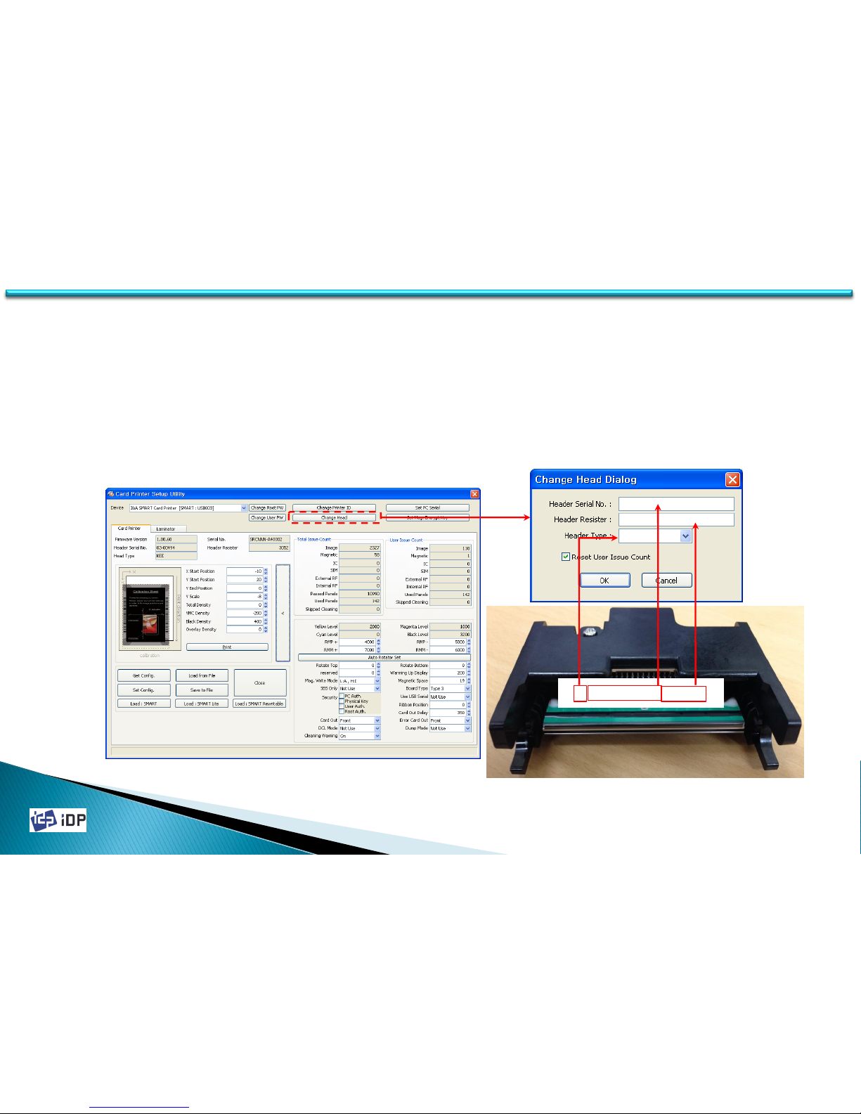
B22001692615
2200169
2615
KPE
4.1.3.6 Thermal Print Head Replacement
To change the print head, the print head module as below photo should be changed. After change the print head
module, its serial no. and register value should be registered. First press “>” button and click “Change Header”
and input the serial no. with the resister value which is described on the print head. “Reset User Issue Count” is
initialization of the printing number.
(After change the thermal print head, the printing position and thickness should be adjusted.)
(See 3.2.1. for Thermal Print Head Replacement mechanically)
4.1 Setup
Page 63
2014-03-24
63
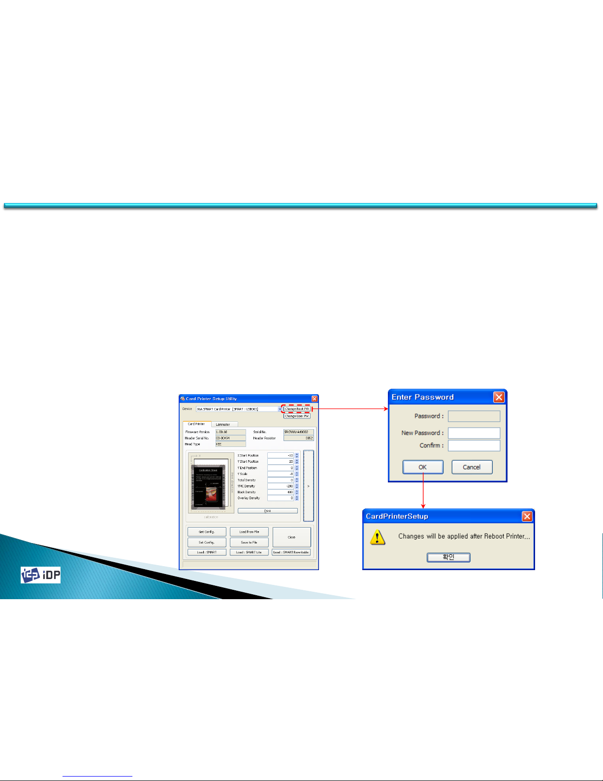
4.1.3.7 Security
• Password
It need to input the password to change the setup value but if you do not set the password, it need not. When
execute CardPrinterSetup program, the password input window will be displayed. If you set the password, it is
saved to SMART Card Printer itself so even if you change the PC, the password is needed for that card printer.
To change the password, click “Change Password” in basic setup window. It will be activated after the printer is
reboot.
(The default is no password setting.)
(If the password is not remember, please contact the manufacturer.)
4.1 Setup
Page 64
2014-03-24
64
4.1 Setup
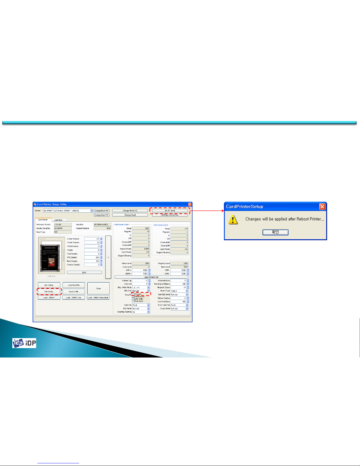
• PC Auth.
PC Auth. is a function to operate a SMART printer with specific PC. This is to prevent the access of unauthorized
person to print card with another printers. Please read as below.
1. In expansion mode, click “PC Auth.” and “Set Config.”
2. Click “Set PC Serial” and save the current PC information to the card printer.
PC Auth. will be activated after the printer’s rebooting. When connect SMART printer which is applied PC
Authentication to the other PC, “Verify Your PC” message will be displayed on the LCD (or Watchman).
(In case PC Witness is activated and PC is not found, please contact I&A system or your distributor.)
Page 65
2014-03-24
65
4.1 Setup
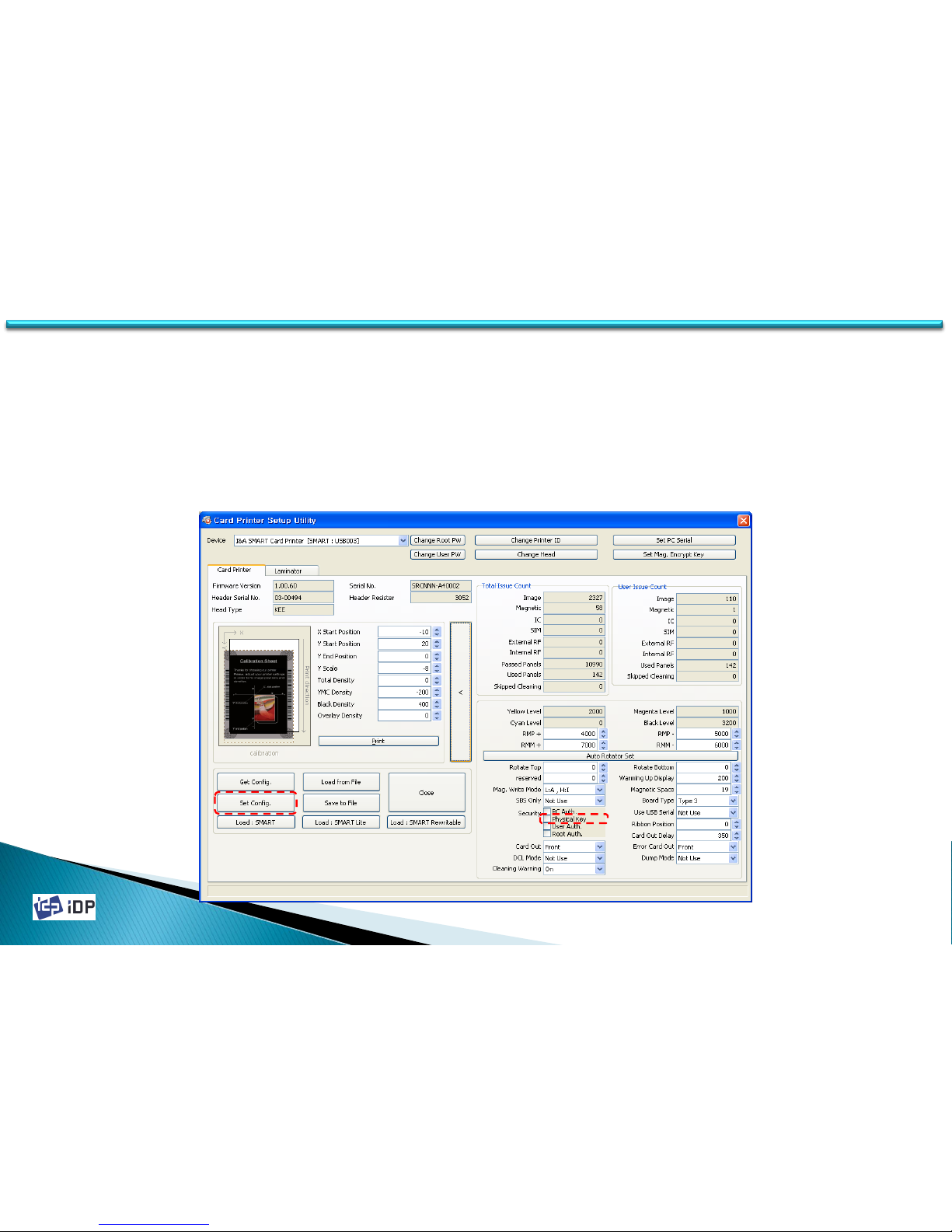
• Physical Key
Physical Key is the function which is enable to operate SMART printer who have the physical key. It is provided as
special option. To use this function, in expansion mode change “Physical Key” to “Use” and press “Set Config.”
Physical Key will be activated after SMART printer reboot. If the printer is locked, “Unlock Please” message will be
displayed on LCD and if not, “System Ready” will be displayed.
Physical Key is electrical key so its setup will be kept when the printer is reboot (power off/on).
Page 66
2014-03-24
66
4.1 Setup
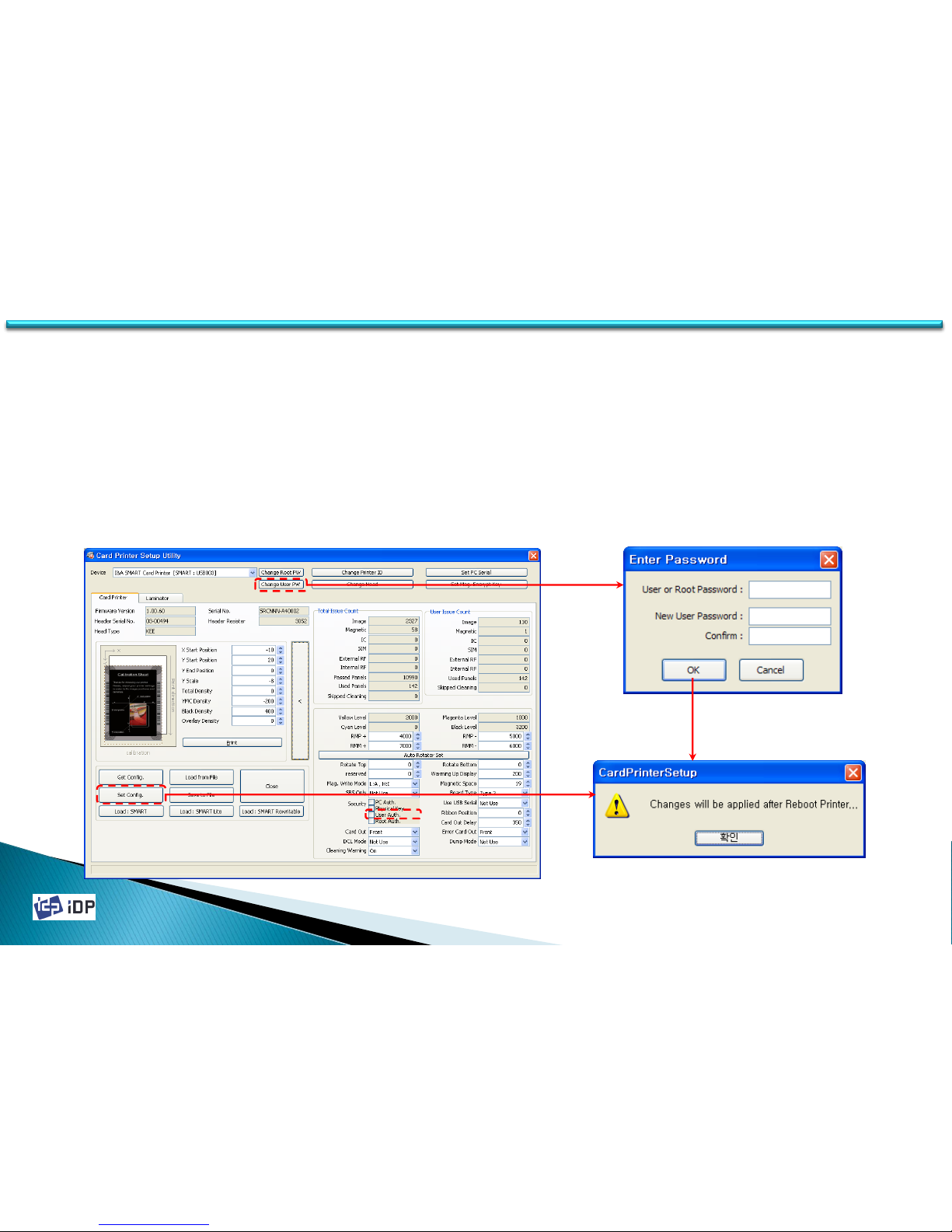
• User Auth.
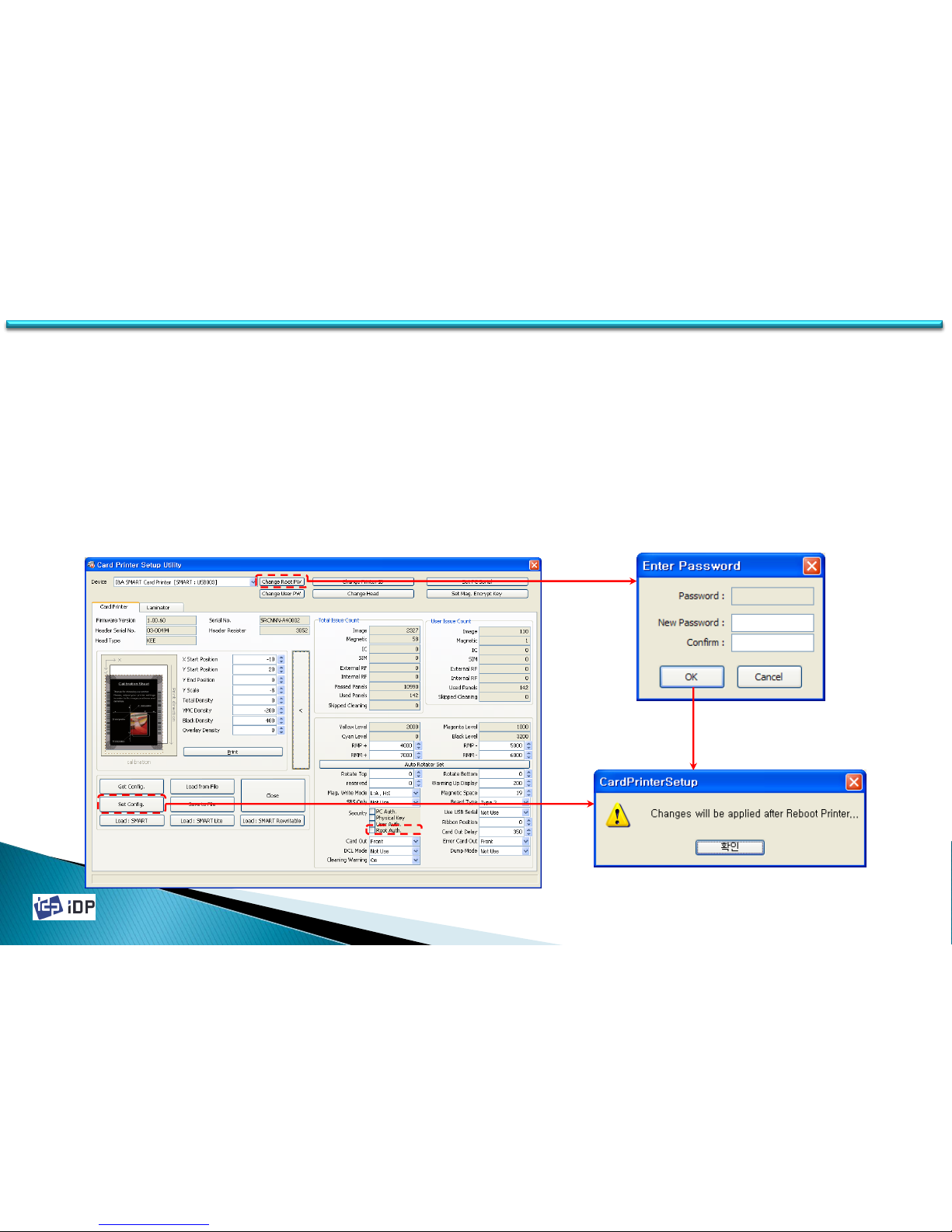
User Auth. allows using PC for someone who knows User password. To activate this function, please tick ‘User
Auth.’ and click ‘Set Config’.
After setting User Auth., this function is activated after re-booting ID card printer. In case printer is locked, LCD
(or Watchman) displays “Unlock Please” message. When you unlock the printer by inputting password using SDK,
“System Ready’ is displayed.
To change password, click ‘Change User Password’ and password change pop up comes up. You can change
password and it will be applied after card printer is re-booted.
Page 67
2014-03-24
67
4.1 Setup
• Root Auth.
Root Witness allows using PC for someone (administrator) who knows Root password.
To activate this function, please tick ‘Root Auth.’ and click ‘Set Config’.
After setting Root Auth., this function is activated after re-booting ID card printer. In case printer is locked, LCD
(or Watchman) displays “Unlock Please” message. When you unlock the printer by inputting password using SDK,
“System Ready’ is displayed.
To change password, click ‘Change Root Password’ and password change pop up comes up. You can change
password and it will be applied after card printer is re-booted.
Page 68
2014-03-24
68
4.1 Setup
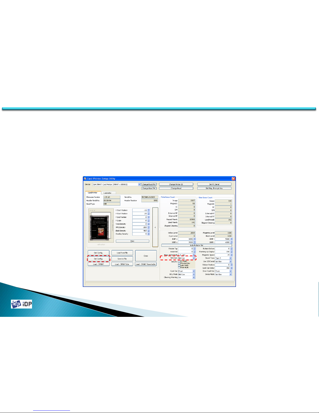
• SBS Only
SMART-30 Printer is provided the printer driver same as other normal printer so it can be used in the application
for SMART card printer and other general application. “SBS Only” function can be realized in the application which
is developed by our SDK.
To use this function, in the expansion mode, change “SBS Only” to “Use” and press “Set Config.”
SBS Only will be activated after SMART printer is reboot. This SBS Only mode is not activated in other general
application.
Page 69
2014-03-24
69
4.1 Setup
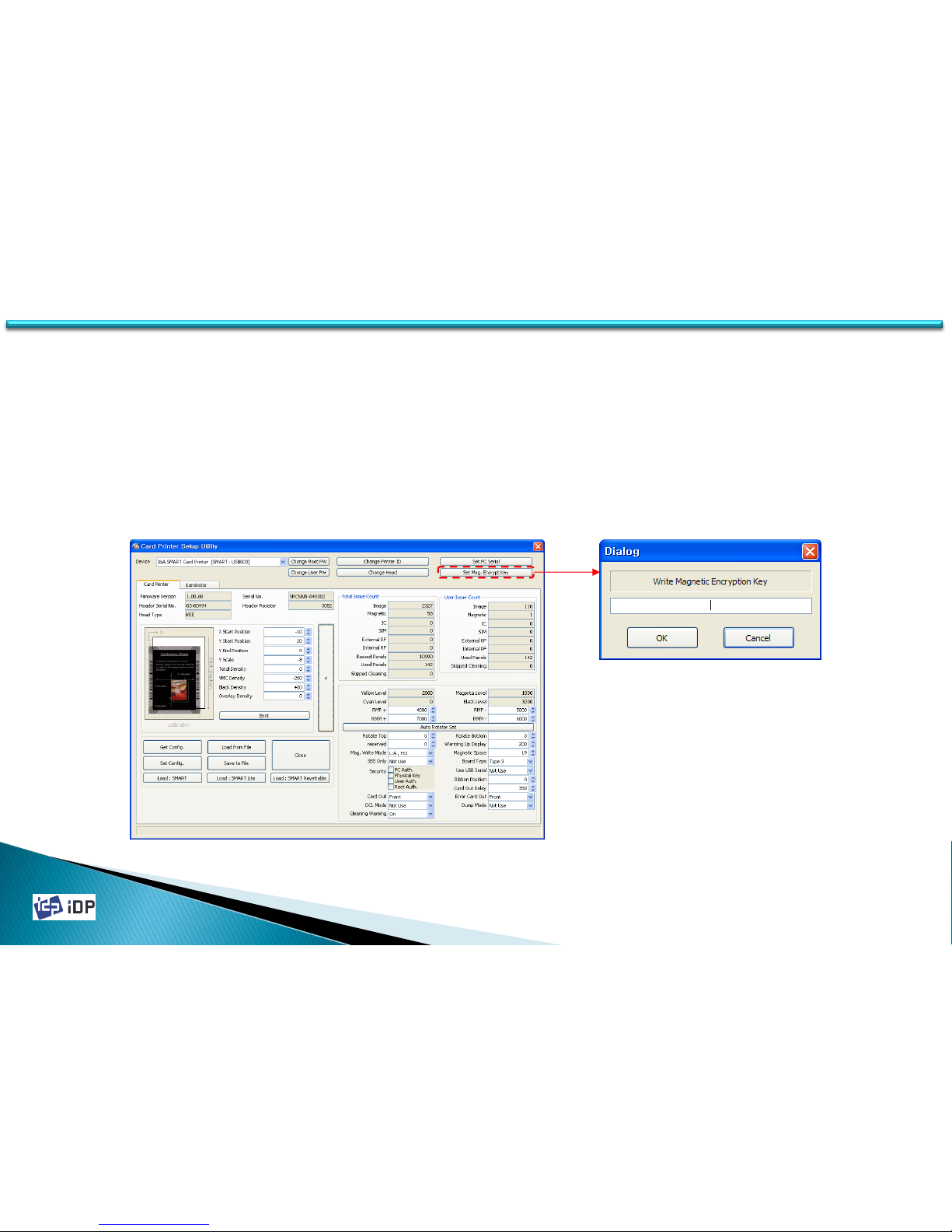
• Magnetic Encryption
If the magnetic stripe card is read and write by SMART printer, the magnetic information can be transfer by USB.
“Magnetic Encryption” is define the key which is used to encrypt the magnetic information to prevent that
information’s hacking between PC and SMART printer.
To use “Magnetic Encryption”, press “Set Mag. Encryption Key” and input the key you want to use to the dialog.
For the encryption, you can use the magnetic read/write encryption key in SDK provided.
Page 70
2014-03-24
70
4.1 Setup
4.1.3.8 Etc.
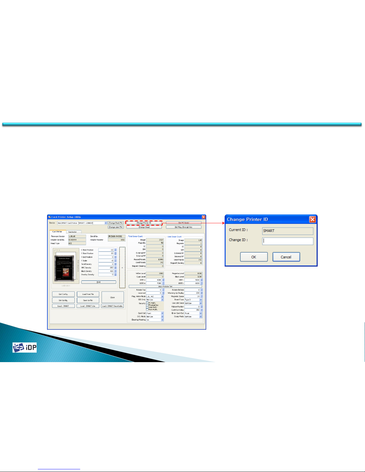
• Printer ID
To use SMART-30 printer’s SDK, you have to set the printer which you want to use. And in this case you need to
get ID to distinguish the printer and it named as Printer ID. Normally we use one PC and one SMART card printer so
do not need to concern. However if use more than one SMART card printer is connected with PC or want to use the
several card printer using networking function, you have to set the different Printer ID per each card printer.
To change Printer ID, press “Change Printer ID” and when there is pop up window, input Printer ID and press O.K.
The changed Printer ID will be activated after rebooting of SMART card printer.
The default Printer ID is “SMART.”
Page 71
2014-03-24
71
4.1 Setup
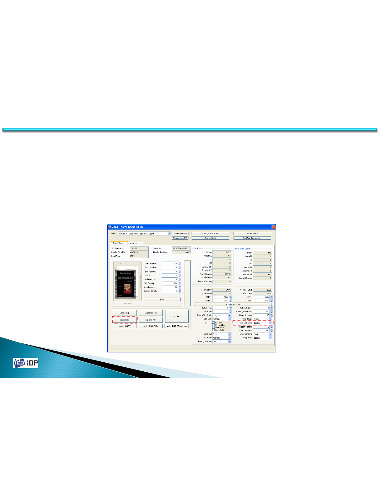
• Use USB Serial
In SMART-30 Card Printer, even if you change the USB port, you do not need to install the printer driver. This is
because their own ID is used in USB communication. Basically every printer have their own ID but considering the
general usage circumstance and the convenience of maintenance, it is set as same ID. So if want to use more than
one printer in one PC, you have set the different ID (this is not same as Printer ID we explained already). Use USB
Serial is ID which is used when the printer is recognized by USB and the serial no. of printer will be used as ID.
To activate Use USB Serial, change “Use USB Serial” to “Use” and press “Set Config.” button. This change will be
activated after SMART printer is reboot.
(When use more than one SMART printer in one PC, “Use USB Serial” should be set as “Use”. If not, PC might be not
working.)
Page 72
2014-03-24
72
4.1 Setup
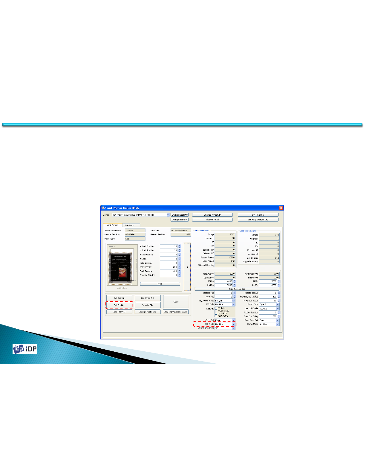
• DCL Mode
With DCL mode, you can control card printer without installation of printer driver. It is operated with DCL order in
SDK. You can control this mode with DCL order in SDK but printer driver installation pop-up appears whenever
card printer is connected.
If you set ‘DCL Mode’ to ‘Use’, it does not use printer driver and previously installed driver becomes off-line.
In order to use DCL mode, please change ‘DCL Mode’ to ‘Use’ and click ‘Set Config’. This function is activated
after card printer is re-booted.
(If DCL mode is activated, you will not use printer on general programs. It is only controlled by DCL order in SDK. )
Page 73
2014-03-24
73
4.1 Setup
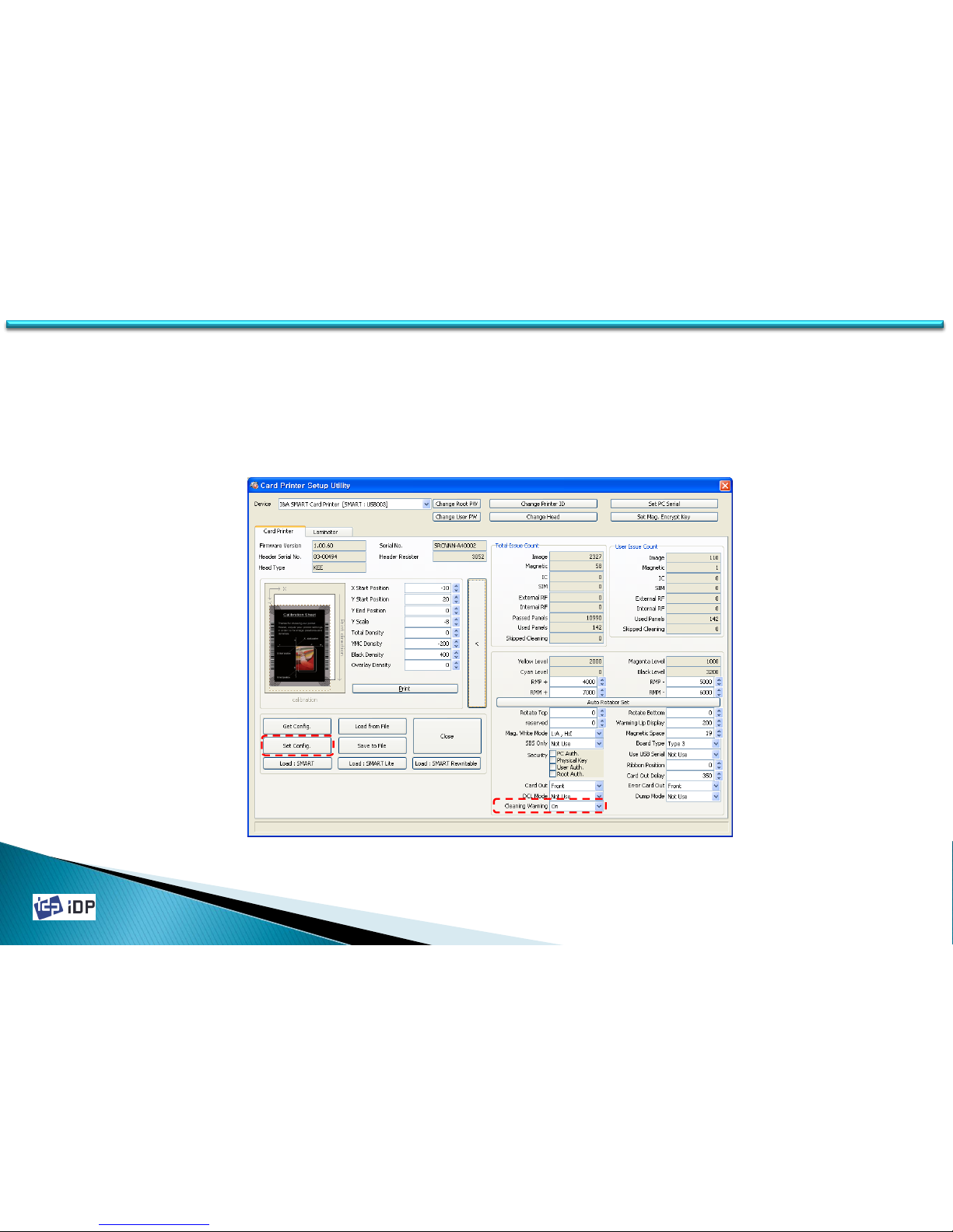
• Cleaning Warning
SMART printer checks the cleaning time. At that time, Cleaning message is displayed in LCD window.
In order not to display the cleaning message, please change ‘Cleaning Warning’ to ‘Off’ and click ‘Set Config’.
This function is activated after card printer is re-booted.
Page 74

2014-03-24
74
4.2 Test
4.2.1 Overview
CardPrinterTest is to test the all function of SMART Card Printer. To operate CardPrinterTest program, the device
driver should be installed to PC and SMART printer should be connected.
Card Printer use the standard printer device driver so it can be printed same as general printer. However if there is
encoder, it need to install the driver which the encoder is required. In this case the printer’s detailed operation can
be controlled using “Card Printer SDK.” CardPrinterTest program is developed by “Card Printer SDK”.
CardPrinterTest is consist of Choice, Control, Print, Allocation, Encode, State, Message.
①Select : Choose the printer when there is more than one printer is connected.
②Control : Order the command such as Card In, Out, Move and Rotate.
③Print : Print the image.
④Allocation : Set the encoding number.
⑤Encoding : Do magnetic stripe encoding, Smartcard and Contactless Smartcard encoding.
⑥State : Check the printer’s state.
⑦Message : Display all kinds of message which displayed when use CardPrinterTest.
4.2 Test
Page 75
2014-03-24
75
4.2 Test
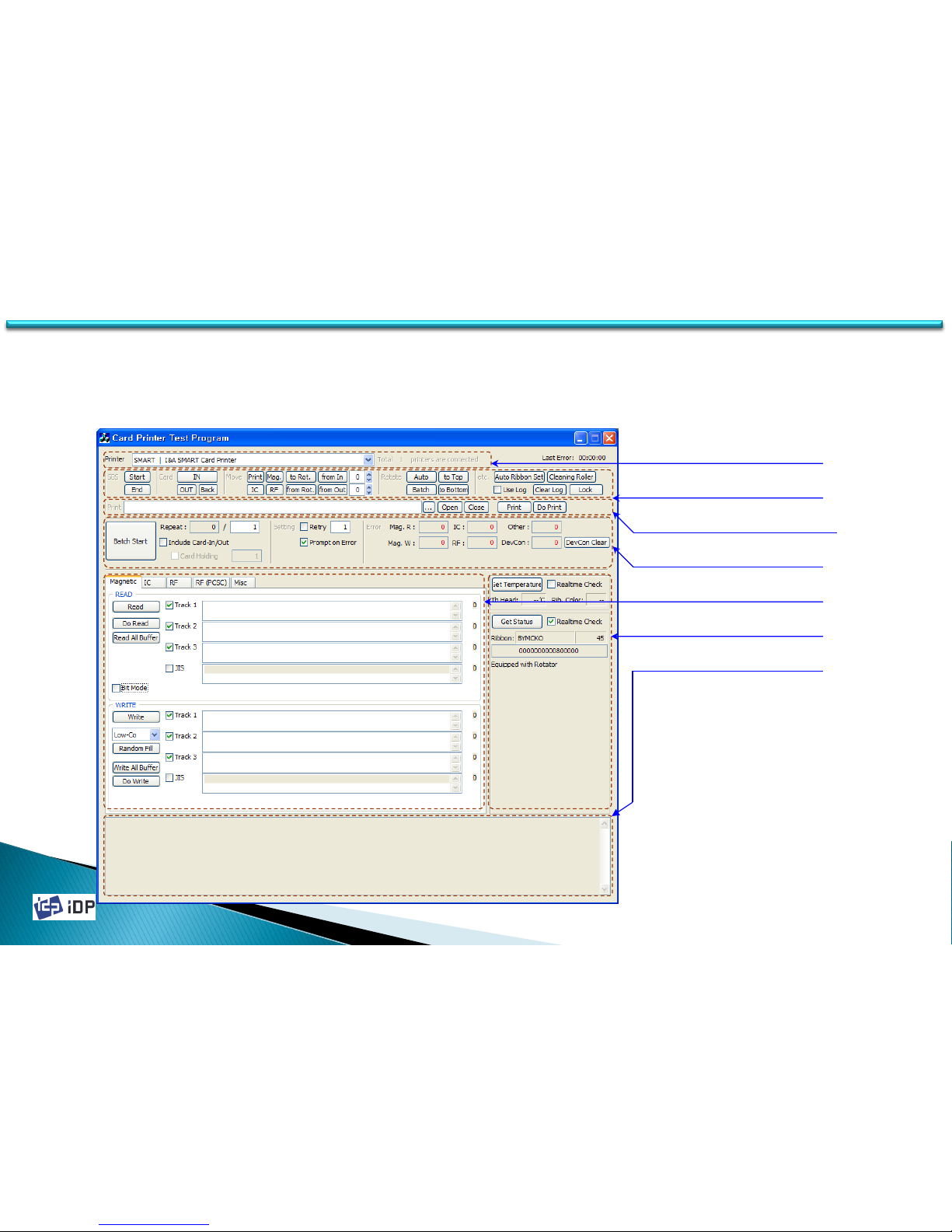
If execute CardPrinterTest program, the following window will be displayed. It is consist of ① Select, ② Control,
③ Print, ④ Allocation, ⑤ Encoding, ⑥ State, ⑦ Message.
① Select
② Control
③ Print
④ Allocation
⑤ Encoding
⑥ State
⑦ Message
Page 76
2014-03-24
76
4.2.2 Basic Operation
4.2.2.1 Selection
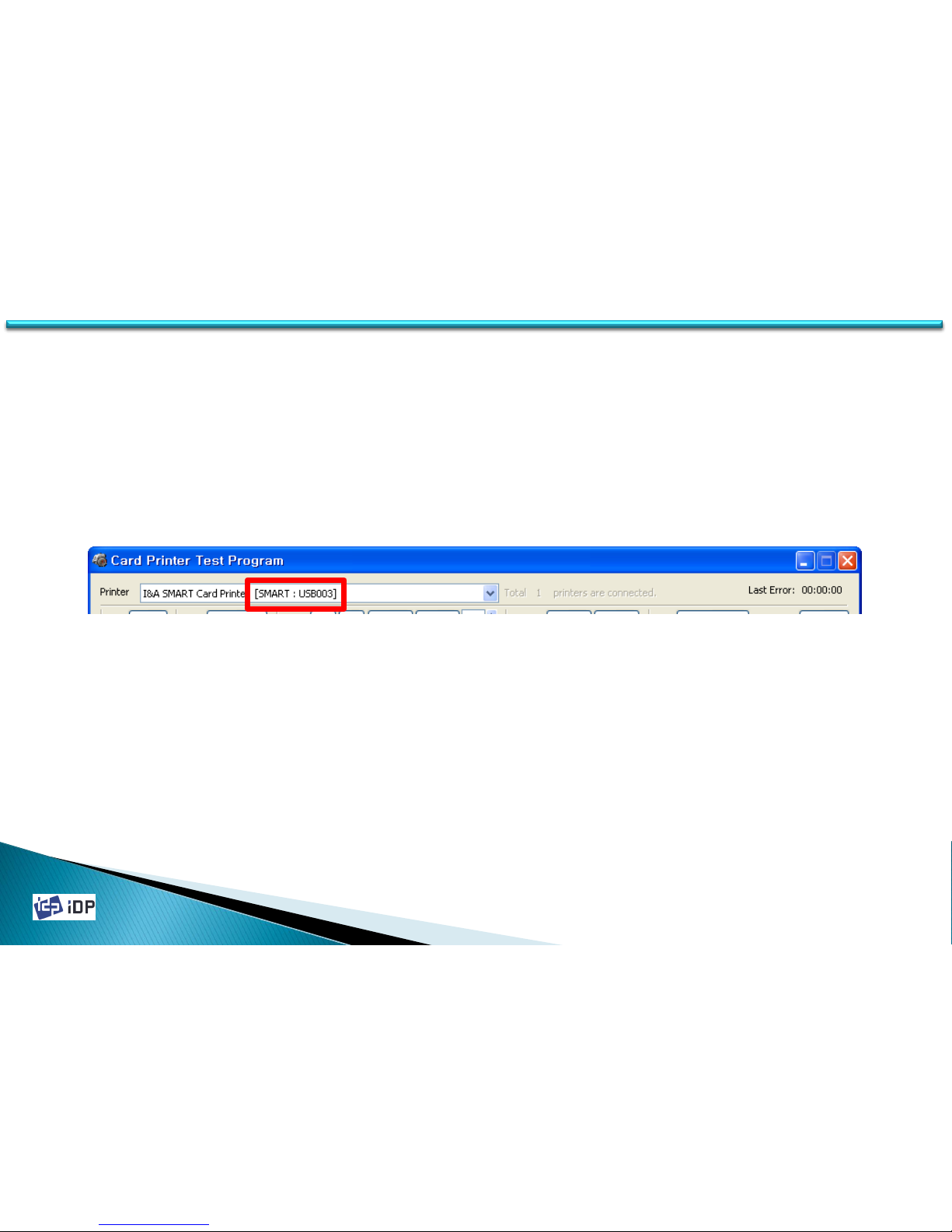
The section next to “Printer” is for the printer selection. If you execute CardPrinterTest program, you can find out
the below thing and show the available printer list, The displayed thing is “Printer ID”. (explained at 4.1 chapter) In
below image, it show there is one printer is connected and its printer ID is “SMART”. Usually one printer is
connected so do not much concern for this matter.
(When connect more than two printers to one PC, use after select “USB Serial” in CardPrinterSetup program.
If the printer selection section is not activated, it means there is no printer connected so please check the printer is ON.)
4.2 Test
Page 77
2014-03-24
77
4.2.2.2 Control
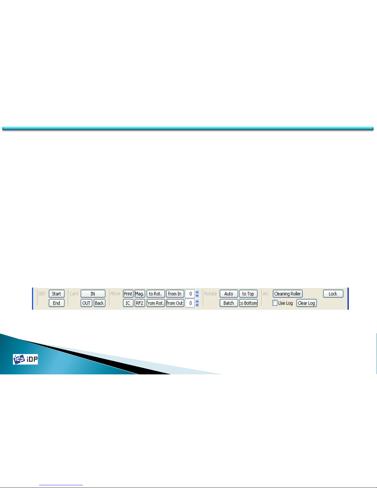
Control is consist of SBS, Card, Move, Rotate, Etc. and it is used to control the printer’s each step.
• SBS is the operation of SBS (Step-By-Step) mode. The user can control SMART printer using the command. The
difference of NORMAL mode and SBS mode is that the printer do printing after get the printing
command(DoPrint). If press “Start” in SBS, SMART printer operate as SBS mode and in this time if there is printer
spool, it will be removed. To close SBS mode, press “Stop”.
• Card is the command for Card In / Out. “IN” is for moving the card to the printer inside and “OUT” is the
command to card out to the stacker. “Back” is to out the card to back side.
• Move is the command to move the card. “Print” is to move the print location, “Mag.” is magnetic location, “IC” is
Smartcard location, “RF” is Contactless Smartcard location, “To Rotate” is move to the inside of rotator, “From
Rotate” is move the card from rotator inside to the printer inside.
• Rotate is for the card flipping. When the card is the printer inside if do “Auto” command, the card is move to
rotator and flip and move to the printing location. “Batch” is repeat as set. “To bottom” is the card flip to back
side. “To Top” is the card flip to front side. For Etc., “Auto Ribbon Set” is automatically set the ribbon. And
using “Use Log”, you can decide to record to the log file or not.
4.2 Test
Page 78
2014-03-24
78
4.2.2.3 Print
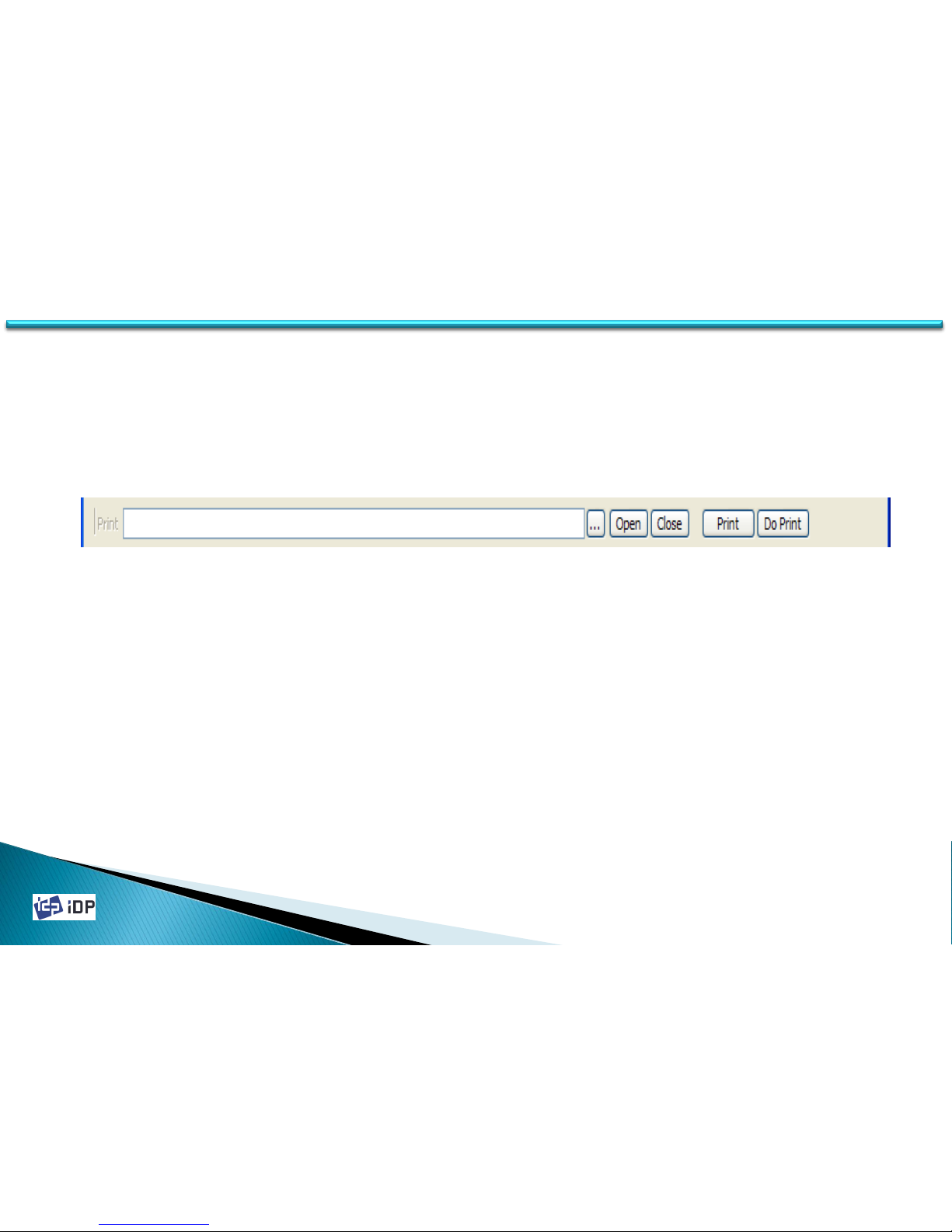
Print can be used to print the designed image which made by Smart Design. To print the card, use “…” and choose
CSD file. Press “Open” and select CSD file and press “Print”.
When the printer is NORMAL state, if you press “Print”, the data is transfer to SMART printer and print. However in
SBS mode, if press “Print”, the data is transfer to SMART printer and waiting the printing command. So in SBS mode,
it need to press “Do Print” for the printing. This function is needed to control the printer in detail.
4.2 Test
Page 79
2014-03-24
79
4.2.2.4 Allocation
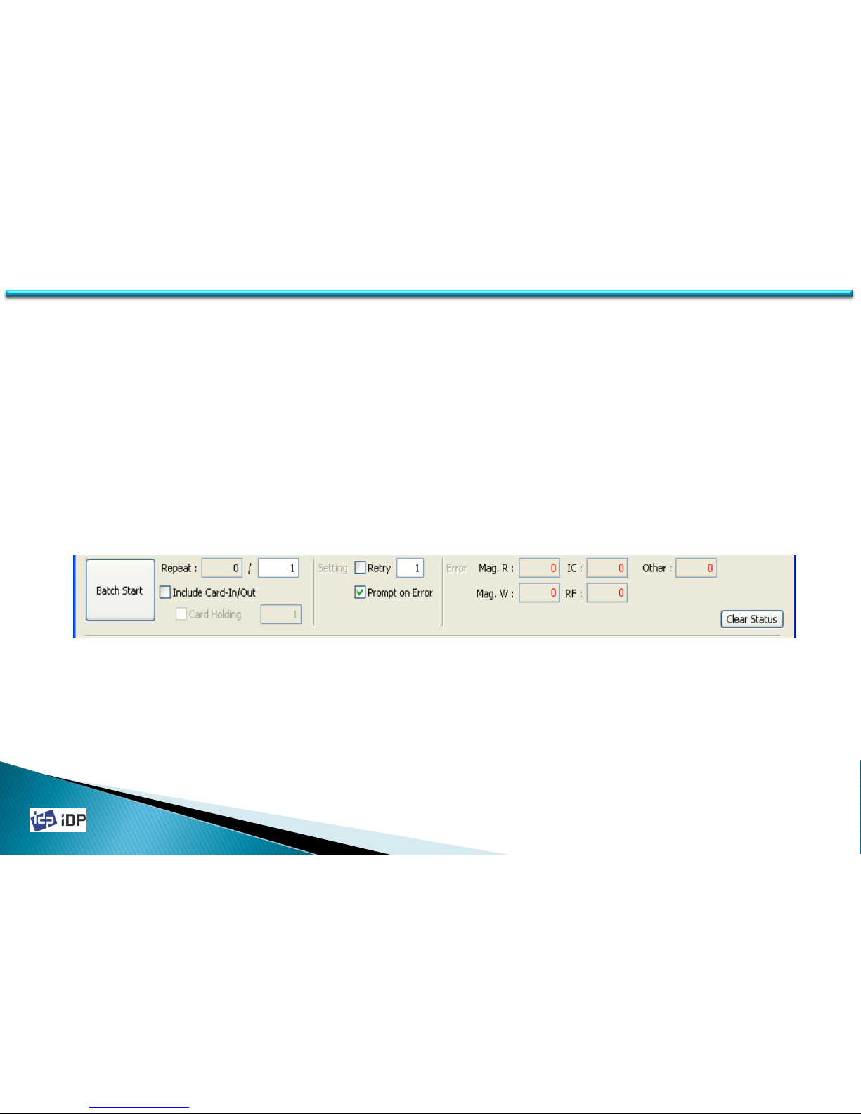
Allocation is used to test the encoding and decoding continually. Set the repeat no. and if press “Batch Start” it
repeat the test. In this case if “Include Card In/Out” section is marked, the card in/out operation is also proceed.
However if it is not checked, use one card continually..
In Strategy, if the retry is not checked, the encoding is placed only one time and it is checked, it is repeat as set
when there is an error. If Prompt on Error is checked, the pop up message will be displayed when there is an error.
And if it is not checked, the test is proceeding after an error is counting.
Error is the error number for each encoding.
4.2 Test
Page 80
2014-03-24
80
4.2.2.5 Status
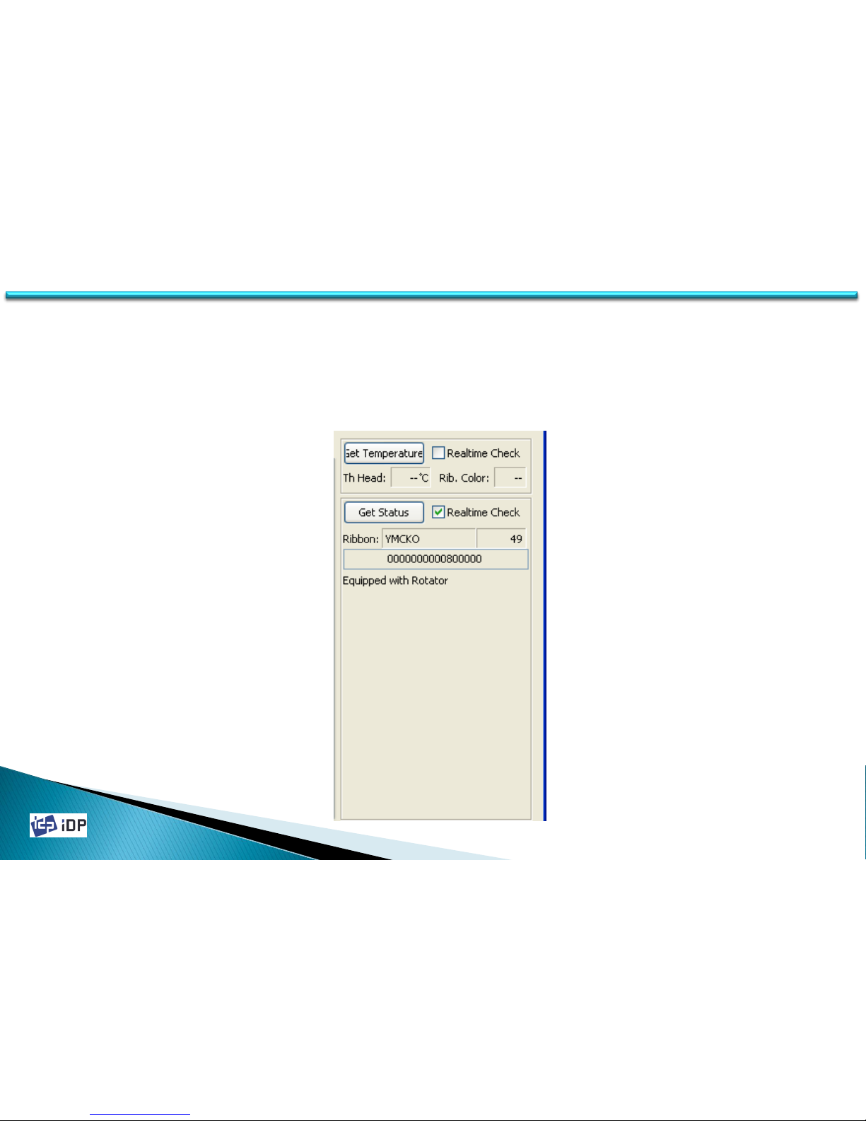
State is to check the printer state. If press “Get Temperature”, it display the thermal head’s temperature. In this
case if check “realtime check”, the temperature is checked on time.
“Get Status” is to check the printer’s state. It show the ribbon balance, printer condition and error state. If check
“realtime”, on time checking.
4.2 Test
Page 81
2014-03-24
81
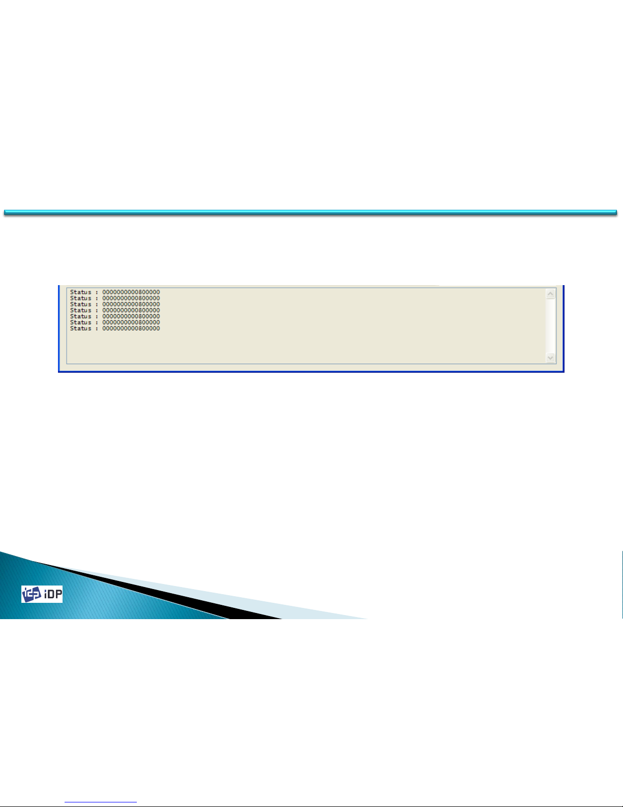
4.2.2.6 Message
It show the communication detail between CardPrinterTest program and SMART Printer so you can check what kind
of command is doing now.
4.2 Test
Page 82
2014-03-24
82
4.2.3 Encoding
4.2.3.1 Magnetic Stripe
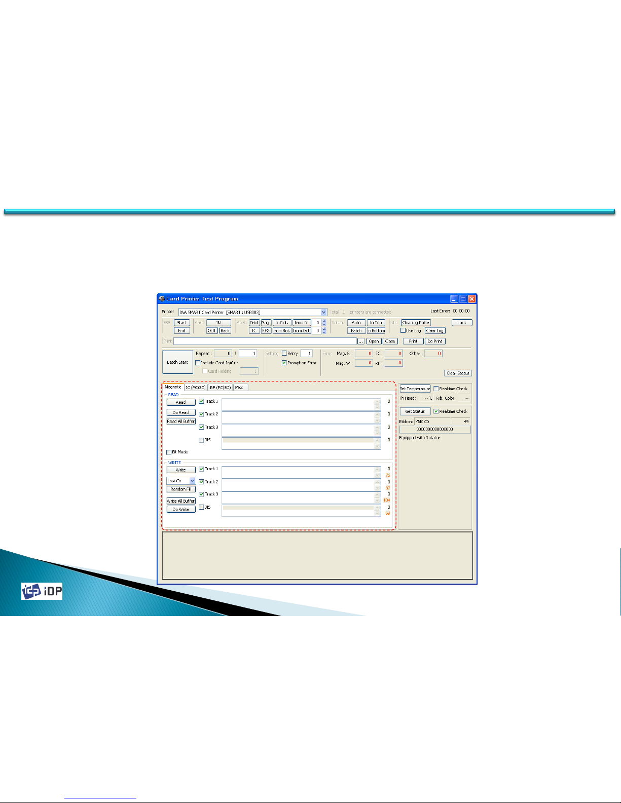
Magnetic encoding is to test the magnetic stripe card when choose “Magnetic” tap as below.
4.2 Test
Page 83

2014-03-24
83
4.2 Test
In Magnetic tap, you can do the read/write of the magnetic stripe card.
“Read” is the reading of the magnetic stripe card and show the date. In fact “Read” is consist of “Do Read” and
“Read All Buffer” but operated at one time. “Do Read” is read the magnetic data in the printer inside. “Read All
Buffer” is bring the data to PC. So “Read” is same as “Do Read” and “Read All Buffer”. Only checked track can be
concerned.
“Write” is the writing of the magnetic stripe card and record the date. “Write” is also consist of “Write All Buffer” and
“Do Write”. “Write All Buffer” is send the encoding date to the printer, “Do Write” is recording the data to the
magnetic card. You can choose “Lo Co”/”Hi Co” as its card type. “Random Fill” is inputting the random date to test.
Page 84
2014-03-24
84
4.2 Test
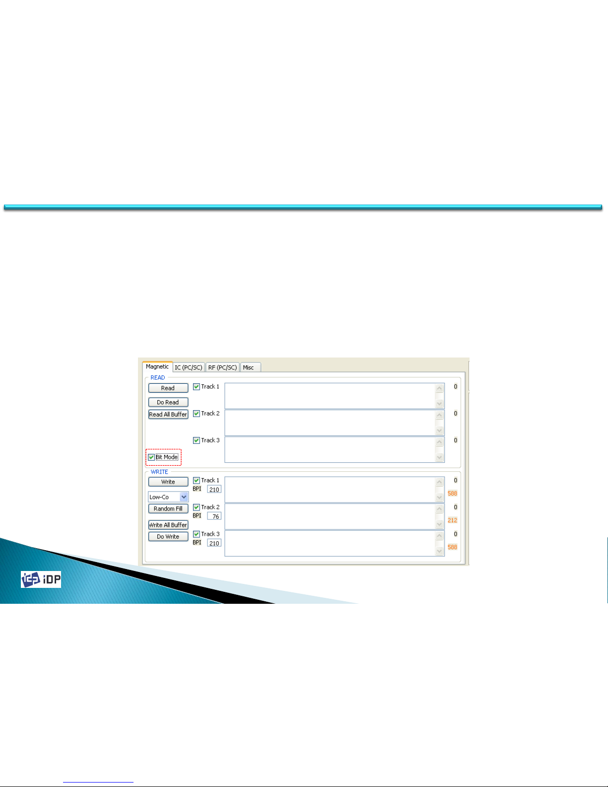
When you tick ‘Bit Mode’, display is changed to Bit Mode writing condition. In the ‘Bit Mode’, you can input data
with ‘0’ and ‘1’ only. You can set BPI information in the ‘Bit Mode’.
BPI range: 210 ~ 40,
You can set BPI value: 210, 168, 140, 120, 105, 93, 84, 76, 70, 64, 60, 56, 52, 49, 46, 44, 42, 40
If you set not defined BPI value, above BPI value is set automatically.
(EX) If you set 170 BPI, it becomes 210 BPI.
Bit which can be written on card may be varied in accordance with BPI. Please refer a formula as below,
Bit can be written = 2.8 X BPI
If you use 210BPI, 2.8 X 210 = 588. SO you can write 588 bit.
Page 85

2014-03-24
85
4.2 Test
If you want to write and read on magnetic in order, you need to do following procedures.
Card “IN” → Move “Mag” → Magnetic “Random Fill” → Magnetic “Write” → Magnetic “Read” → Card “OUT”
When you select ‘Magnetic’ on the encoding selection tap and click “Batch Start”, magnetic encoding is repeated as
below.
Page 86
2014-03-24
86
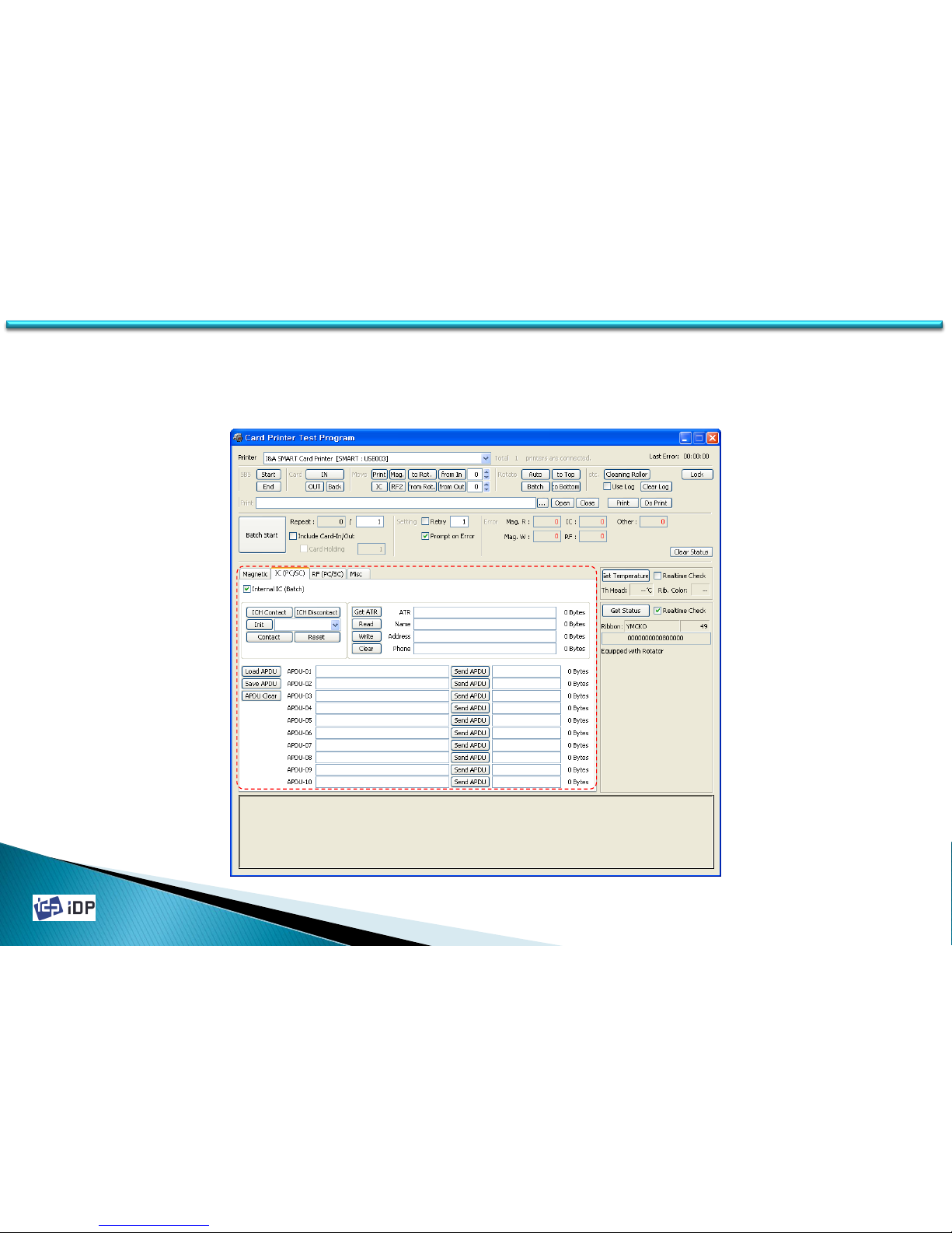
4.2.3.2 Contact Smart Card
Contact Smartcard encoding is enable to encode the date to Smartcard when you choose the IC tap.
4.2 Test
Page 87

2014-03-24
87
4.2 Test
In IC tap, the read/write of Smartcard is possible.
“ICH Contact” is the command to contact the head with Smartcard chip. “ICH Discontact” is the dis-contact
command. “Init” is the initialization of the installed IC reader. The installed IC reader will be displayed on right
down control board. “Contact” is contacting between the IC head and Smartcard. “Reset” is stop to use.
After “Contact”, “Get ATR”, “Read”, “Write” and “Clear” command are possible to operate. “Get ATR” is loading ATR
value of Smartcard. “Read” is reading such as name, address, phone data. “Write” is writing.
If read/write the date directly using APDU command, you can use the following APDU command. “Load APDU” is
load the saved APDU command. “Save APDU” is save the current APDU command. “Clear APDU” is clear the APDU
screen. To see the individual APDU command, press “Send APDU” on the line..
To write and read on Smartcard, you have to proceed the following procedure.
Card “IN” → Move “IC” → IC “ICH Contact” → IC “Init” → IC “Contact” → IC “Write” → IC “Clear” → IC “Read” → IC
“Reset” → IC “ICH Dis-contact” → Card “OUT”
If press “Batch Start”, IC encoding will be repeated. SMART Printer is support the internal Smartcard encoder and
external SIM encoder. SIM is not possible to move automatically so the batch is not possible for SIM.
Page 88
2014-03-24
88
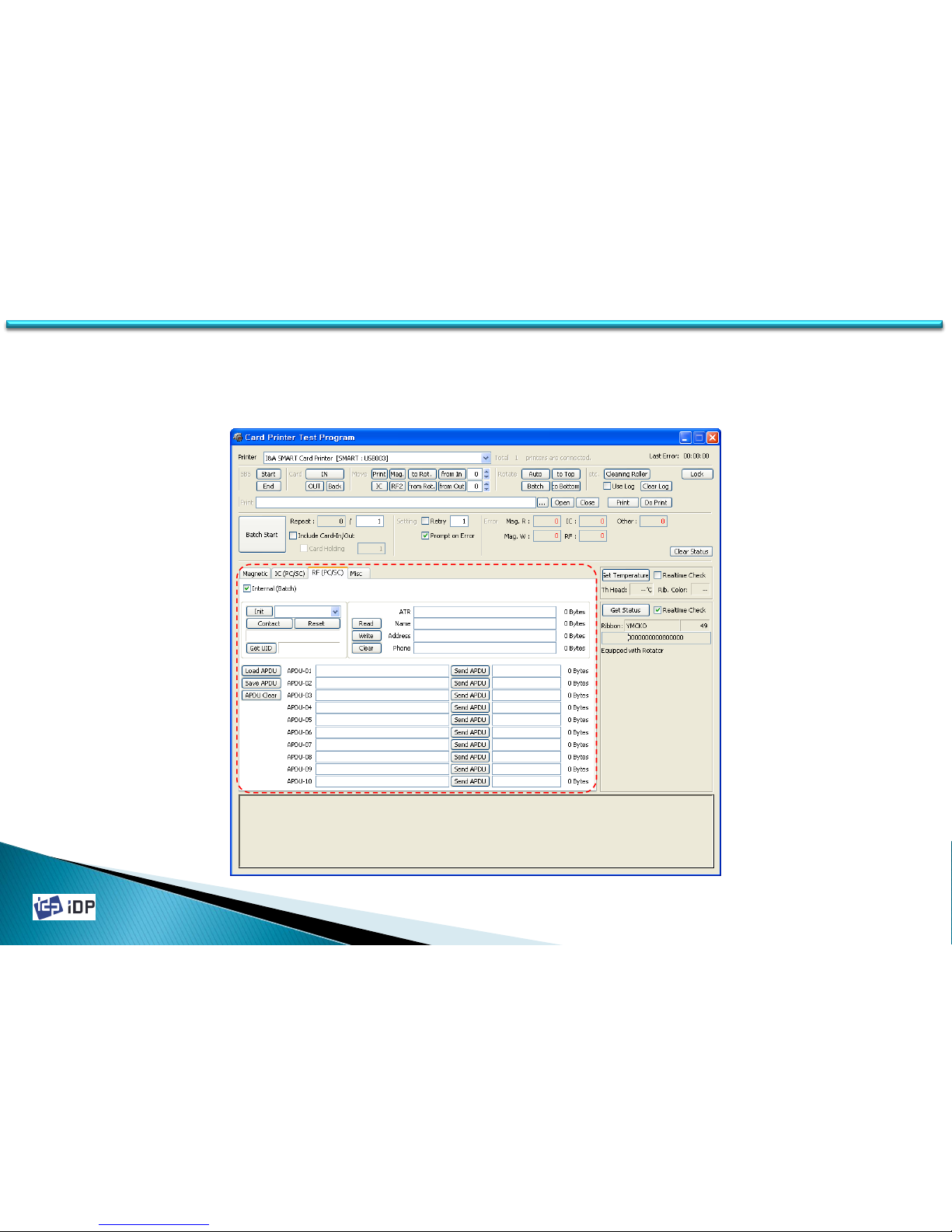
4.2.3.3 Contactless (PC/SC) Smart Card
Smartcard encoding through PC/SC – The contactless smartcard can be tested through PC/SC protocol after select
“RF (PC/SC)” tap of CardPrinterTest program.
4.2 Test
Page 89

2014-03-24
89
4.2 Test
In RF (PC/SC) tap, the read & write to the contactless smartcard can be done.
“Init” is the command to show the installed PC/SC type reader. The available reader will be shown to the left full
down control. “Contact” is the command for the connection to the contactless smartcard and “Reset” is the
disconnection.
After “Contact”, “Get UID”, “Read”, “Write” and “Clear” can be executed. “Get UID” is the reading command for RF
chip’s serial value. “Read” is also the reading command for the data such as name, address and phone which are
predefined. “Write” is the writing command for name, address and phone.
When read and write to the contactless smartcard using APDU command, you can use the below APDU command.
“Load APDU” is loading of the saved APDU command and “Save APDU” is saving the current displayed APDU
command. “Clear APDU” is clearing. To send the individual APDU command, you just press “Send APDU” which you
want.
To write and read from the contactless smartcard, you have to follow the below procedure.
Card “IN” → Move “from In (-62)” → RF (PC/SC) “Init” → RF (PC/SC) “Contact” → RF (PC/SC) “Write” → RF (PC/SC)
“Read” → RF (PC/SC) “Reset” → Card “OUT”
After select “RF (PC/SC)” in tap, if you press “Batch Start”, the encoding will be repeated. SMART printer have the
internal installed contactless smartcard encoder and external installed contactless smartcard encoder. For the
external contactless smartcard encoder, you can test by not marking “Internal (Batch)” item.
Page 90

2014-03-24
90
4.2 Test
4.2.4 Status
4.2.4.1 Printer Status Code
SMSC_M_CARDIN 0x0000000000000001 // Under Card In
SMSC_M_CARDOUT 0x0000000000000002 // Under Card Out
SMSC_M_MOVE_PRINT 0x0000000000000004 // Move to Printing Position
SMSC_M_MOVE_PRN2ROT 0x0000000000000008 // Move to Flipper from Printer
SMSC_M_MOVE_ROT2PRN 0x0000000000000010 // Move to Printer from Flipper
SMSC_M_MOVE_IC 0x0000000000000020 // Move to IC Position
SMSC_M_MOVE_RF 0x0000000000000040 // Move to RF Position
SMSC_M_MOVE_MAG 0x0000000000000080 // Move to Magnetic Stripe Position
SMSC_M_THUP 0x0000000000000100 // Thermal Print Head Up
SMSC_M_THDOWN 0x0000000000000200 // Thermal Print Head Down
SMSC_M_ICHUP 0x0000000000000400 // IC Head (Contactor) Up
SMSC_M_ICHDOWN 0x0000000000000800 // IC Head (Contactor) Down
SMSC_M_PRINT 0x0000000000001000 // Under Printing
SMSC_M_MAGRW 0x0000000000002000 // Magnetic Stripe Read/Write
SMSC_M_SEEKRIBBON 0x0000000000004000 // Searching Ribbon
SMSC_M_MOVERIBBON 0x0000000000008000 // Moving Ribbon
SMSC_M_ROTATORTOP 0x0000000000010000 // Card Front Side Flipping to Up
SMSC_M_ROTATORBOTTOM 0x0000000000020000 // Card Front Side Flipping to Down
SMSC_S_HOPPERHASCARD 0x0000000000040000 // Card is in the Hopper
SMSC_S_CLEANWARNING 0x0000000000080000 // Need to cleaning State (After firmware 1.00.60)
SMSC_S_CARDIN 0x0000000000100000 // Card Detection by Card In Sensor
SMSC_S_CARDOUT 0x0000000000200000 // Card Detection by Card Out Sensor
SMSC_S_EQUIPLAMINATOR 0x0000000000400000 // Laminator is installed (After firmware 1.00.60)
SMSC_S_EQUIPROTATOR 0x0000000000800000 // Flipper is installed
SMSC_M_RECVPRINTDATA 0x0000000001000000 // Receiving Printing Buffer
SMSC_S_HASPRINTBUFFER 0x0000000002000000 // Reserving Printing Data Buffer
SMSC_M_SBSRUNNING 0x0000000004000000 // Doing SBS Command
SMSC_S_SBSMODE 0x0000000008000000 // SBS Mode State
SMSC_S_CASEOPEN 0x0000000010000000 // Case Open State
SMSC_M_INIT 0x0000000020000000 // Under Initialization
SMSC_S_TESTMODE 0x0000000080000000 // Test Mode State
Page 91

2014-03-24
91
4.2 Test
Status codes are changed after Printer firmware 1.00.60 as below.
SMSC_S_CLEANWARNING 0x0000000000080000 // Need to cleaning State (After f/w 1.00.60)
SMSC_S_THUP 0x0000000000080000 // Thermal Print Head Up state (Before f/w 1.00.60)
SMSC_S_EQUIPLAMINATOR 0x0000000000400000 // Laminator is installed (After f/w 1.00.60)
SMSC_S_ROTATORTOP 0x0000000000400000 // Card Front Side is up at Rotator (Before f/w 1.00.60)
Page 92

2014-03-24
92
4.2.4.2 Printer Error Code
SMSC_F_CARDIN 0x0000000100000000 // Card In Fail
SMSC_F_MOVETOPRINT 0x0000000200000000 // Moving to Printing Position is Fail
SMSC_F_CARDOUT 0x0000000400000000 // Card Out is Fail
SMSC_F_MOVETOMAG 0x0000000800000000 // Moving to Magnetic Position is Fail
SMSC_F_MOVETOIC 0x0000001000000000 // Moving to IC Position is Fail
SMSC_F_MOVETORF 0x0000002000000000 // Moving to RF Position is Fail
SMSC_F_MOVETOROTATOR 0x0000004000000000 // Moving to Flipper is fail
SMSC_F_MOVEFROMROTATOR 0x0000008000000000 // Moving to Printer from Flipper is Fail
SMSC_F_THUP 0x0000010000000000 // Thermal Print Head Up Fail
SMSC_F_THDOWN 0x0000020000000000 // Thermal Print Head Down Fail
SMSC_F_ICHUP 0x0000040000000000 // IC Head (Contactor) Up Fail
SMSC_F_ICHDOWN 0x0000080000000000 // IC Head (Contactor) Down Fail
SMSC_F_ROTATORTOP 0x0000100000000000 // Card Front Side Flipping to Up is Fail
SMSC_F_ROTATORBOTTOM 0x0000200000000000 // Card Front Side Flipping to Down is Fail
SMSC_F_PRINT 0x0000400000000000 // Error in Printing
SMSC_F_MAGRW 0x0000800000000000 // Magnetic Stripe Track Read/Write Fail
SMSC_E_SEEKRIBBON 0x0001000000000000 // Ribbon Search Error
SMSC_E_MOVERIBBON 0x0002000000000000 // Ribbon Move Error
SMSC_E_NOTH 0x0004000000000000 // Thermal Print Head is not Installed
SMSC_E_THOVERHEAT 0x0008000000000000 // Thermal Print Head Overheat
SMSC_E_EMPTYRIBBON 0x0010000000000000 // Empty Ribbon
SMSC_F_DATA 0x0020000000000000 // Printing Data Error
SMSC_F_CARDBACKOUT 0x0040000000000000 // Card Back Out Fail
SMSC_F_CARDERASE 0x0080000000000000 // Card Data Erase Fail
SMSC_F_INCORRECT_PW 0x0100000000000000 // Incorrect Password
SMSC_F_MAGREADT1 0x0200000000000000 // Magnetic ISO Track 1 Read Fail
SMSC_F_MAGREADT2 0x0400000000000000 // Magnetic ISO Track 2 Read Fail
SMSC_F_MAGREADT3 0x0800000000000000 // Magnetic ISO Track 3 Read Fail
SMSC_F_LOCKED 0x1000000000000000 // Printer Locked
SMSC_F_SPOOLFULL 0x2000000000000000 // Spooler Full
SMSC_F_SET 0x4000000000000000 // Recently Printer Operation Fail
4.2 Test
Page 93
2014-03-24
93
4.3 Firmware
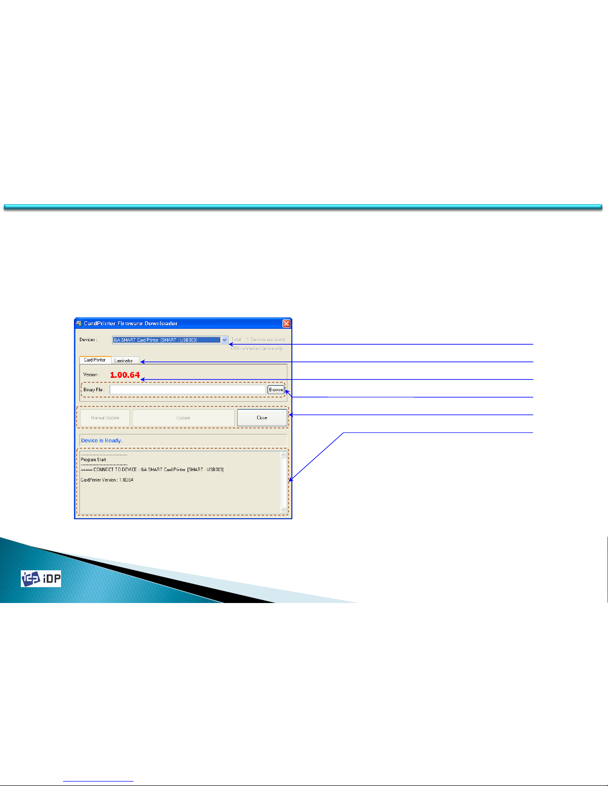
4.3.1 Overview
CardPrinterFirmware is the software for changing the firmware of SMART printer. The firmware of SMART printer is
the operating software for the processor of SMART printer. If new function is added or there is other reason, it will
be provided by web-site or distributor.
4.3 Firmware
Printer ID
Device selection tab
Current firmware version
New firmware
Main buttons
Messages
Page 94
2014-03-24
94
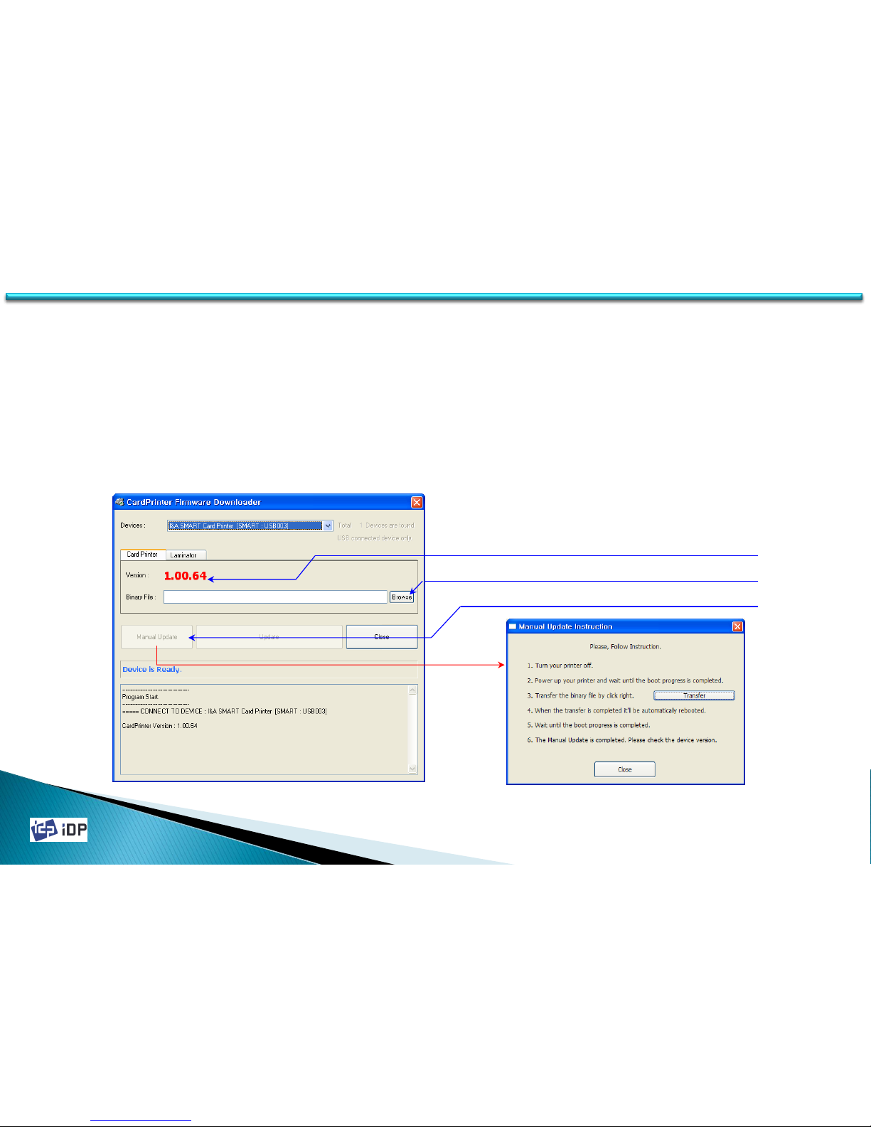
4.3.2 Automatic Update
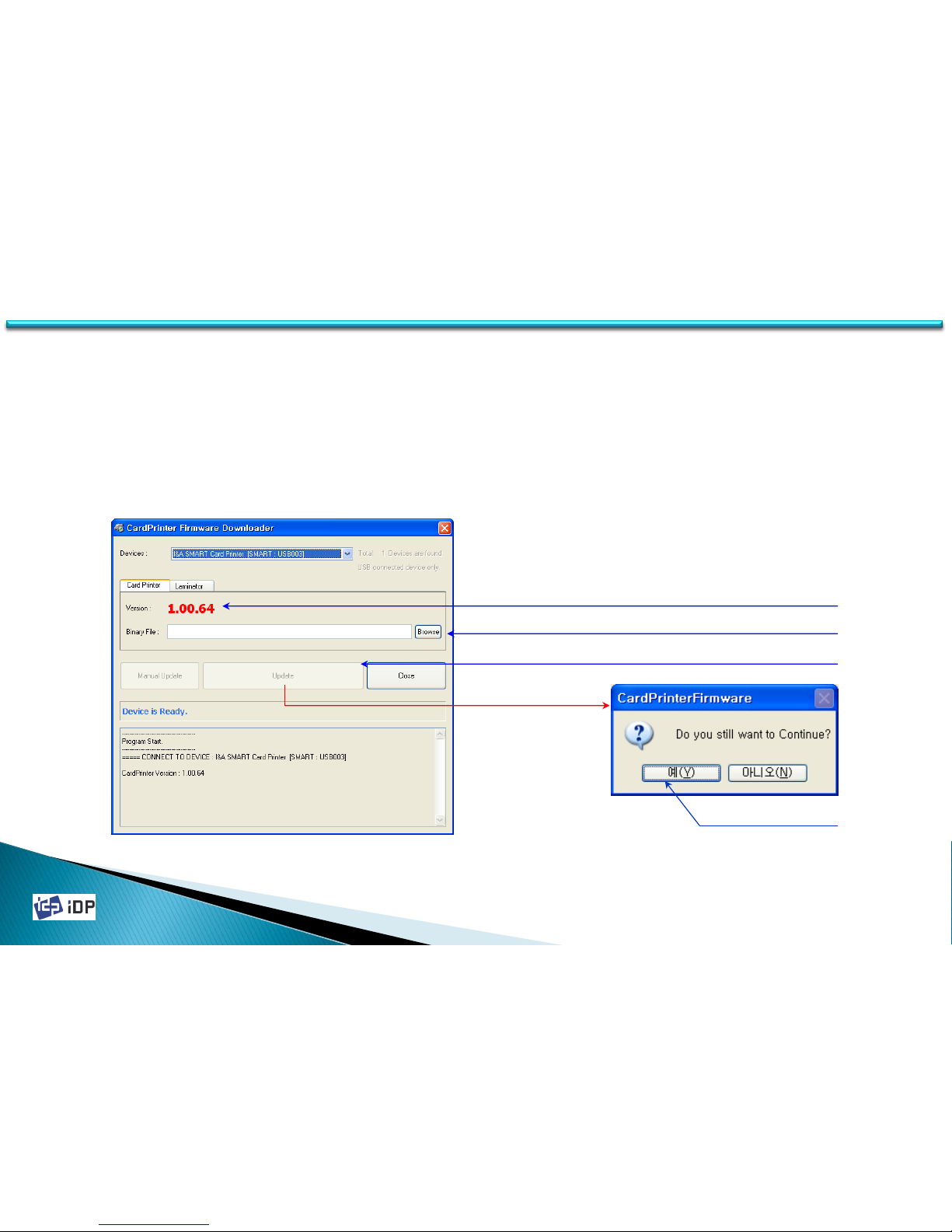
Printer Update is the same as Laminator Update. The upgrade procedure is as follows.
1.Check the current printer’s firmware version.
2.Press “Browse” button and select the firmware you want to install.
3.Press “Update” button and update.
4.Click “OK” on dialogue message to continue the update.
5.Waiting until the firmware update is finished.
4.3 Firmware
1. Check current firmware version
2. Browse new firmware
3. Push Update buttons
4. Push OK button
( In firmware update, the printer is automatically rebooted.)
( During update, please do not operate the printer or close the program.)
Page 95
2014-03-24
95
4.3.5 Manual Update
Manual update procedure is as follows.
1.Check the printer’s firmware version.
2.Press “Browse” button and select the firmware you want to install.
3.If press “Manual Update”, “Manual Update Instruction” window will be displayed.
4.Follow “Manual Update Instruction”.
5.If press “Transfer” and transferring is complete, window will be closed.
6.Waiting until the firmware update is finished.
4.3 Firmware
1. Check current firmware version
2. Browse new firmware
3. Push “Manual Update” button
( In firmware update, follow the instruction and do not operate other thing.)
Page 96
2014-03-24
96
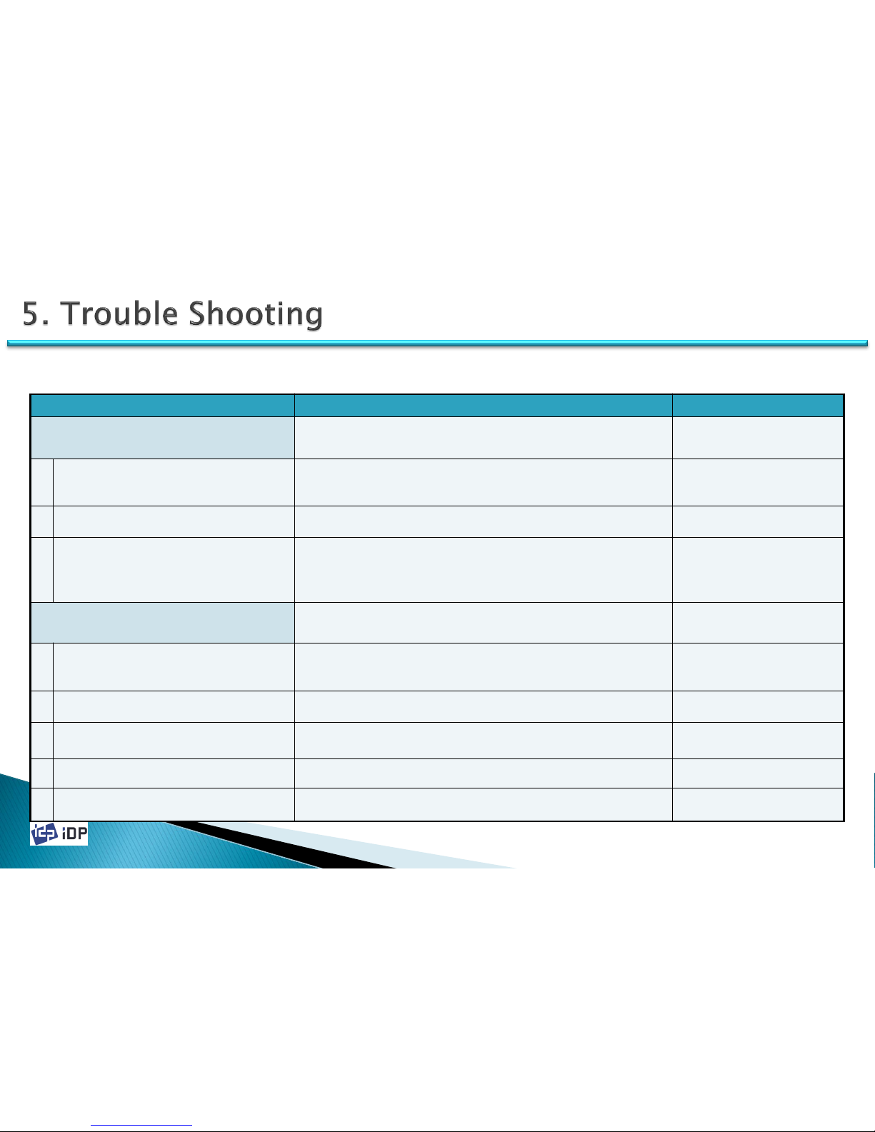
5.1 General Operation
Symptom Countermeasures Related Parts
When the ribbon is torn
Open the top cover and pull out the ribbon cartridge. Connect the ribbon
and install again. If the problem is occurred too often, refer to the below
countermeasures.
1
The card is out of specification or the surface
is not even
Check the card specification or change to the new one.
2 The color density setting is too high Refer to the manual 4.1.3.2 and adjust the printing density.
3 The card printing position is not proper
Adjust the image start position as 0.5mm from the card starting point. If
the problem is not solved, refer to the manual 4.1.3.1.
Ribbon is not recognized. – There will be displayed
“
Ribbon Not Found” error message.
Press the left button of front LCD to replay. If the problem is not solved,
refer to the below countermeasures.
1 Ribbon tag is bad Change to the new ribbon.
2 All ribbon is used Change to the new ribbon.
3 Ribbon is torn Open top cover and pull out the ribbon cartridge. Connect the ribbon.
4 Thermal print head is not properly installed Refer to the manual 3.2.1 and check the Print Head installation state.
5 Ribbon is not authorized one Change to the authorized one.
5.1 General Operation
Page 97
2014-03-24
97
Symptom Countermeasures Related Parts
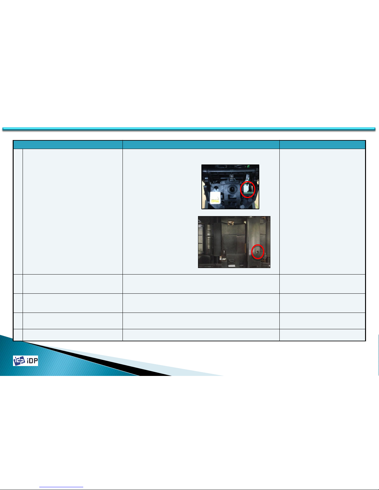
6 Color In Sensor or Color Out Sensor is bad
When Color In/Out Sensor have some problem, replace the sensors.
Change the Color In Sensor
- Manual 3.2.4
Change the Color Out Sensor
630026(SENSOR COLOR OUT2
BD,SMART,0.3)
630024(SENSOR COLOR IN
BD,SMART,0.4)
7 Encoder sensor or connection cable is bad
Bad connection status of sensor cable may make this error (See 2.1)
Refer to the manual 3.4.3 and replace the cable or sensor.
630033(SENSOR ENCODER2
BD,SMART,0.1)
611076(WIRE,I/O_30 LEFT,20P,230mm)
8 Ribbon RF Board or connection cable is bad
Refer to the manual 3.3.2 and check Ribbon RF Board and connection
state.
630020(RIBBON RF,SMART,0.2)
9 Ribbon RF Board’s connection cable is bad Refer to the manual 3.3.2 and change the connection cable.
611079(FFC CABLE,240mm,16P,
0.5mm,2896 C-type)
10 Main board is bad Refer to 3.3.1 and replace the main board. 630083 (MAIN BD,SMART,0.57)
5.1 General Operation
Page 98
2014-03-24
98
Symptom Countermeasures Related Parts
Printer is not working even if the printing data is
sent or the printer is not booting.
Refer to the below countermeasures.
1 Printer power is off. Power on the printer.
2 Using another DC adaptor. Check DC adaptor and use our adaptor which supplied with the printer.
3 Printer driver is not online but offline. Change to the online.
4
USB cable for the communication is not
connected or the connection is bad
Check the state and plug out and in for USB cable.
5
Printing is not proceeded by the proper printer
driver
Print through the proper printer driver
6 Printer driver port setting is wrong. Check the printer driver port setting is USB port.
7
There is no ribbon in the printer or the printer
have an error.
Install the ribbon or clear the printer error refer to this manual.
8 Ribbon balance is 0. Change to the new ribbon.
9
Power and communication cable are too long.
(Power cable : Over 1.5 M, communication
cable : Over 1.8M)
Using the cable which supplied from us.
10 USB port of PC is down. Reboot PC.
11 The printer communication USB cable is bad Change USB cable.
610120(CABLE,USB2AB1,1.8M,
USB1.0)
12 Power adaptor is bad Call to the nearest dealer and change it.
610697(ADAPTOR,STD2427P,24V/2.7A,-)
13 Printer is bad The printer should be replaced
5.1 General Operation
Page 99
2014-03-24
99
Symptom Countermeasures Related Parts
Card is not inserted from the hopper
Press the left key on the front side of printer to replay. If it is
not moving and the problem is happen so often, please refer to
the below countermeasures.
1 Card size is not correct or it is not proper card
If the card is not in specification., it might be not inserted to the
hopper. It should be changed.
2
The setting of card thickness control lever is not
correct
Refer to 1.2.2 and adjust the card thickness .
3 Card arrangement is not proper
Arrange the cards as the manual 1.2.3 and put the cards again
to the hopper.
4 There is electrical static or moisture on the card
Arrange the cards as the manual 1.2.3 and put the cards again
to the hopper.
5 The hopper unit or connection cable are bad
If the card hopper is totally not working, check the connection
of card hopper and if there is no problem, the hopper cable and
hopper should be changed.
630097(HEAD UD MOTOR_30
BD,SMART30,0.1)
611076(WIRE,I/O_30
LEFT,20P,230mm)
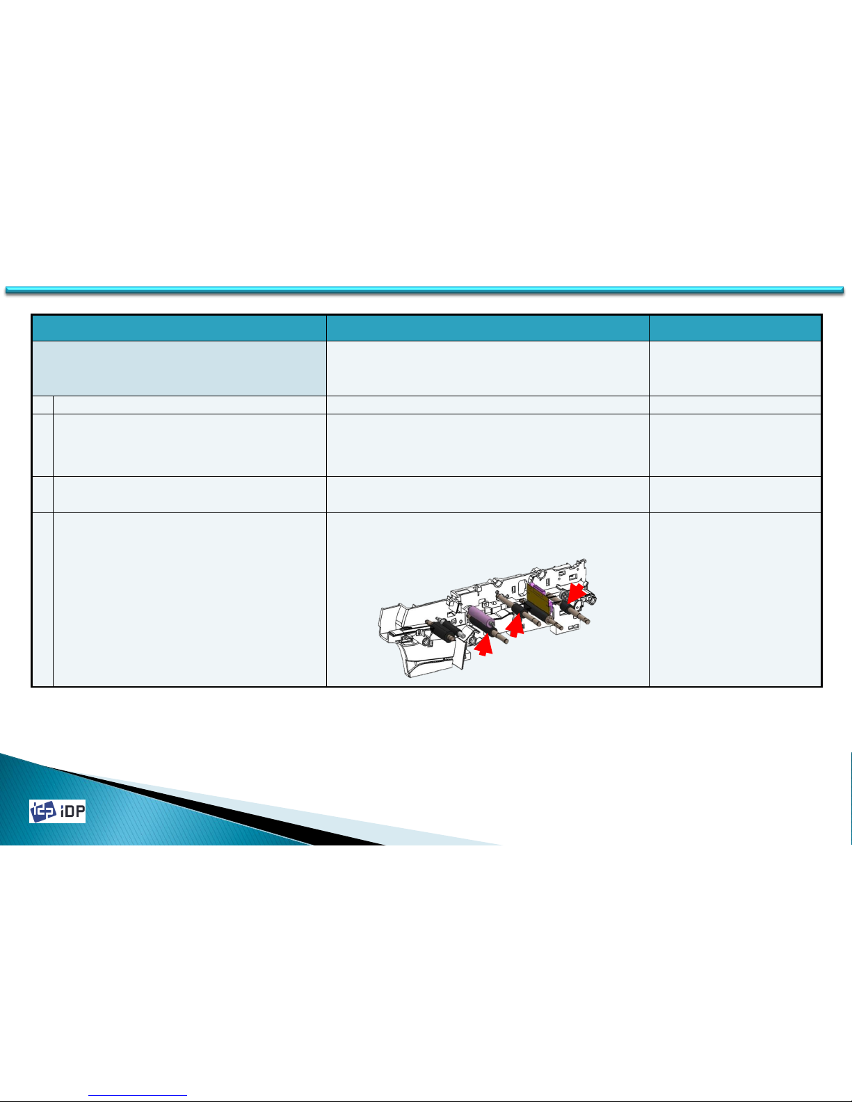
When there is moving error as the ribbon is rolled to the
printing roller or movement rollers.
Open the top cover, remove the ribbon which rolled to the card
and roller using the front LCD buttons. If the problem is happen
so often, please refer to the below countermeasures.
1 Card size is not correct or it is not proper card
If the card size is more large or small, the printing position
might be not correct. Refer to the manual 4.1.3.1 and reset the
printing position or change the card.
2 The printer’s printing position is set no properly
If the card size is more large or small, the printing position
might be not correct. Refer to the manual 4.1.3.1 and reset the
printing position.
5.2 Card Moving
5.2 Card Moving
Page 100
2014-03-24
100
Symptom Countermeasures Related Parts
When there is an error during card movement
Press the left key on the front side of printer to replay. If it not
moving and the problem is happen so often, please refer to the
below countermeasures.
1 Card size is not correct or it is not proper card Change to the proper card.
2 Using another DC adaptor.
Some problem might be happened if use another DC Adaptor
which is not supplied with the product. Please check DC Adaptor.
※ If use other DC Adaptor, Magnetic stripe encoding error or
other operation problem can be occurred.
3 There is dust on the surface of cards Clean the card or change to new card.
4 There is dust on the moving rollers
Clean the cleaning roller using the cleaning card kit. The related
rollers are IC roller, cleaning roller fixed, MS(Magnetic Stripe)
roller.(See 2.2 Thermal Head and Rollers)
5.2 Card Moving
 Loading...