

IDK VAC-5000HD User Manual
VAC-5000HD User’s Guide
ON
OFF
DISTRI BUTI O N AMPLIFIER for HDMI
VAC-5000HD
POWER SIGNAL
HDMI Distribution Amplifier (with Audio D/A converter)
VAC-5000HD
User’s Guide Ver.1.0.0
● Thank you for choosing this IDK product.
● To ensure the best performance of this product, please read this User’s Guide fully and carefully before
using it and keep this manual beside this product.
IDK Corporation

VAC-5000HD User’s Guide
Trademarks
The terms HDMI and HDMI High-Definition Multimedia Interface, and the HDMI Logo are trademarks or
registered trademarks of HDMI Licensing, LLC in the United States and other countries.
All other company and product names mentioned in this manual are either registered trademarks or
trademarks of their respective owners. In t hi s manual, the “®” or “™” marks may not be specified.
2

VAC-5000HD User’s Guide
Before reading this manual
● All rights reserved.
● Some of the contents in this User’s Guide such as appearance diagrams, menu operations,
communication commands, and so on may di ffer depending on the version.
● This User’s Guide is subject to change without notice. You can download the latest version from IDK’s
website at: http://www.idk.co.jp/en/index.html
FCC STATEMENT
This equipment has been tested and found to comply with the limits for a Class A digital device, pursuant to
part 15 of the FCC Rules. These limits are designed to provide reasonable protection against harmful
interference when the equipment is operated in a c ommercial environment. This equipment generates, uses,
and can radiate radio frequency energy and, if not installed and used in accordance with the instruction
manual, may cause harmful interference to radio com munications. Operation of this equi pment in a resident ial
area is likely to cause harmful interference and the use r wil l be required to correct that interference at their
own expense.
CE MARKING
This equipment complies with the essential requirements of the relevant European health, safety and
environmental protection legislation.
WEEE MARKING
Waste Electrical and Electronic Equipment (WEEE), Directive 2002/96/EC
(This directive is only valid in the EU.)
This equipment complies with the WEEE Directive (2002/96/EC) marking requi rement.
The left marking indicates that you must not discard this electrical/electronic equipment in
domestic household waste.
3
VAC-5000HD User’s Guide
Enforcement Symbol
Description
Symbol
Description
Example
Instruction
Unplug
Caution
Warning
Safety instructions
Read and understand all safety and operating instructions before using this product. Follow all instructions
and cautions as detailed in this document.
Caution
Prohibition
Indicates the presence of a hazard that may resul t in death or serious
personal injury if the warning is ignored or the equipment i s handled
incorrectly.
Indicates the presence of a hazard that may cause minor personal
This symbol is indicated to alert the user. (Warning and caution)
This symbol is intended to prohibit the user from acti ons.
injury or property damage if the caution is ignored or the equipment is
handled incorrectly.
Electrical
Hazard
Do not
disassemble
This symbol is intended to instruct the user.
4
VAC-5000HD User’s Guide
Do not place the product in any unstable place.
Install the product to a horizontal and stable place. Otherwise, it may fall/turn over and lead to injury.
Do not place the product in any environment with vibration.
Otherwise, it may move/fall and lead to injury.
Keep out any foreign objects.
from the vent holes.
For power cable/plug:
damaged, contact IDK.
disassemble
Do not repair, modify or disassemble.
In the event of lighting or thunder, do not touch the main unit and cables such as
For installation:
or IDK. Otherwise, it may cause fire, electric shock, injury, or property damage.
Set the power plug in a convenient place to unplug easily.
when you do not use it for a long period.
Plug the power plug into appropriate outlet completely.
plug or loosened outlet.
Clean the power plug regularly.
If the plug is covered in dust, it may cause fire due to reduced insulating power.
Unplug immediately if the product smokes, makes unusual noise, or smells.
the product stops smoking, contact IDK.
Unplug immediately if you drop the product or if the cabinet is damaged.
and repair, contact IDK.
Unplug immediately if water or other objects are directed inside.
contact IDK.
For connection
Warning
Prohibition
Do not
Do not touch
In order to avoid fire or electric shock, do not allow foreign objects, such as metal and paper, to enter the product
● Do not scratch, heat, or modify, including extending them
● Do not pull, put heavy stuff on them, or pinch them.
● Do not bend, twist, or tie them together forcefully.
If they are used in those states continuously, it may cause fire or electric shock. If power cables/plugs become
Since the product includes high-voltage parts, those actions may cause fire or electric shock. For internal
inspections or repairs, contact IDK.
power cable and LAN cable.
Contact may cause electric shock
Instruction
Unplug
The product is intended to be installed by skilled technicians. For installation, please contact a system integrator
You can easily unplug in case of any extraordinary failure or abnormal situation, and it also helps for unplugging
If the plug is plugged incompletely, it may overheat which causes electrical shock or fire. Do not use damaged
If you continue to use the product under those situations, it may cause electric shock or fire. After confirming that
If you continue to use the product under those situations, it may cause electrical shock or fire. For maintenance
If you continue to use it under those situations, it may cause electrical shock or fire. For maintenance and repair,
Differences in ground potential among the product and peripheral devices may cause electric shock or damage
of the devices. When using cables to connect devices, including connection of long-distance transmission,
unplug the power cables of all related devices.
Instruction
After connecting signal/control cables of each device, plug in the power cables of each device.
5
VAC-5000HD User’s Guide
For installation
Instruction
Instruction
Do not block the vent holes.
Do not plug or unplug with wet hands.
Use and store the product within the specified temperature/humidity range.
Caution
Prohibition
No wet hands
Do not place the product in any place where it will be subjected to high
temperatures.
If the product is subjected to direct sunlight or high temperatures, it may cause fire.
Do not place the product in humid, oil smoke, or dusty place.
If the product is placed near humidifiers or dusty area, it may cause fire or electric shock.
If ventilation slots are blocked, it may cause fire or failure due to internal heat.
Do not put heavy items on the product.
It may fall/turn over and lead to injury.
Do not exceed ratings of outlet and wiring devices.
If several plugs are put in an outlet, it may cause fire and electric shock.
Use only the provided AC adapter and power cable.
If non-compliant adapter or power cables is used, it may cause fire or electrical shock. Use the provided AC power
connection cable. If you want to use your product in other countries that use different AC power cables, contact
IDK.
It may cause electrical shock.
Instruction
Unplug
If the product is used outside the range continuously, it may cause fire or electric shock.
Turn off devices when they are connected to another device.
It may cause fire or electric shock.
Unplug the power plug if you do not use the product for a long period.
In case of defect, it may cause fire.
Unplug the power plug before cleaning.
It may cause electric shock.
For rack mount devices:
Mount the product to the rack meeting EIA standards, and m aintain spaces above and
below for air cooling. For your safety, attach an L-shape bracket in addition to the mount
bracket kit for the front panel to balance the weig ht.
Instruction
For devices with rubber feet:
Never insert only the screws into the holes after removing the rubber feet. It may lead to
damage when the screws contact electrical circui t or parts inside of the product.
To put the rubber feet back on, use only provided rubber feet and screws.
Altitude:
Do not place the product at elevations of 2,000 meters (6562 feet) or higher above sea
level. Failure to do so may shorten the life of the int ernal parts and result in malfunctions.
6

VAC-5000HD User’s Guide
Table of Contents
1 Included items ............................................................................................................................................. 9
2 Product outline .......................................................................................................................................... 10
3 Features .................................................................................................................................................... 11
4 Part names and descriptions .................................................................................................................... 12
4.1 Front panel .......................................................................................................................................... 12
4.2 Rear panel .......................................................................................................................................... 13
5 Connecting external devices ..................................................................................................................... 14
5.1 Preparation ......................................................................................................................................... 14
5.2 Precautions before connection ........................................................................................................... 15
5.3 Typical application .............................................................................................................................. 16
6 Basic operation ......................................................................................................................................... 17
6.1 Menu operation keys .......................................................................................................................... 17
6.2 Initialization ......................................................................................................................................... 18
7 Menus ....................................................................................................................................................... 19
7.1 Menu list .............................................................................................................................................. 19
7.2.20 [F90] Displaying firmware vers .................................................................................................... 20
7.2 Setting input and output (Setting menu) ............................................................................................. 21
7.2.1 [F01 to F03] Copying EDID ......................................................................................................... 21
7.2.2 [F10] Setting EDID resolution...................................................................................................... 22
7.2.3 [F12] Setting external EDID ........................................................................................................ 24
7.2.4 [F14] Setting copy EDID .............................................................................................................. 24
7.2.5 [F16] Setting No-signal input monitoring time of Video signals .................................................. 25
7.2.6 [F20] Setting Deep Color ............................................................................................................. 26
7.2.7 [F22] Setting PCM Audio ............................................................................................................. 26
7.2.8 [F24] Setting AC-3 Dolby Digital Audio ....................................................................................... 26
7.2.9 [F26] Setting AAC Audio ............................................................................................................. 27
7.2.10 [F28] Setting Dolby Digital Plus Audio ........................................................................................ 27
7.2.11 [F30] Setting DTS Audio ............................................................................................................. 28
7.2.12 [F32] Setting DTS-HD Audio ....................................................................................................... 28
7.2.13 [F34] Setting Dolby TrueHD Audio .............................................................................................. 29
7.2.14 [F36] Setting Audio channel ........................................................................................................ 30
7.2.15 [F38] Setting CEC physical address copy of EDID ..................................................................... 31
7.2.16 [F40] Setting input equalizer ....................................................................................................... 31
7.2.17 [F42] Selecting EDID for WXGA ................................................................................................. 32
7.2.18 [F60 to F64] Setting output equalizer .......................................................................................... 32
7.2.19 [F70 to F74] Setting audio output ................................................................................................ 32
7.2.20 [F90] Displaying firmware version ............................................................................................... 33
7.2.21 [F91] Displaying hardware version .............................................................................................. 33
7.2.22 [F99] Setting maintenance/status display menu ......................................................................... 33
7.3 Checking operation (Maintenance menu) ........................................................................................... 34
7.3.1 [C01] Setting HDCP input ........................................................................................................... 34
7.3.2 [C10] Setting how long video output requests of sink device are ignored .................................. 35
7.3.3 [C20 to C24] Setting forced HDMI output mode ......................................................................... 35
7.3.4 [C30 to C34] Setting color conversion output manually .............................................................. 36
7.4 Displaying input/output statuses ......................................................................................................... 37
7.4.1 [L01 to L13] Displaying input information .................................................................................... 37
7

VAC-5000HD User’s Guide
7.4.2
[L30 to L94] Displaying output information .................................................................................. 40
8 Specifications ............................................................................................................................................ 41
8.1 Pin assignments .................................................................................................................................. 41
8.1.1 HDMI Type A connector .............................................................................................................. 41
8.2 Product specification ........................................................................................................................... 42
9 Troubleshooting ........................................................................................................................................ 44
10 Fuse .......................................................................................................................................................... 48
8
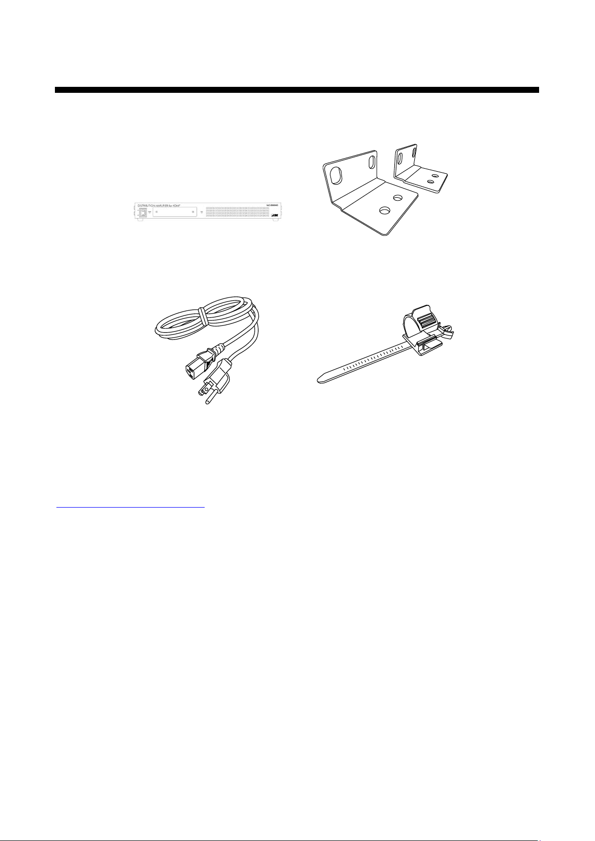
1 Included items
Power cable (1.8m/5.9 feet) x1
Cable clamp x 6
Make sure all items below are included in the package.
If any items are missing or damaged, please contact us.
VAC-5000HD main unit x 1
VAC-5000HD User’s Guide
Rack mounting bracket x 2
[Fig. 1.1] Included items
You can download the latest version of the User’s Gui de from IDK’s website at:
http://www.idk.co.jp/en/index.html
9
VAC-5000HD User’s Guide
5
distribution
EDID
emulator
Input EQ
VAC-5000HD
D/A
conversion
Analog audio
L/R unbalanced
outputs
1
Digital video and audio
HDMI DVI
outputs
5
Output EQ
Max. 50 m/
164.04 feet
Max.
50
m/
164.04 feet
Video/Audio
Audio
Digital video and audio
HDMI DVI
outputs
1
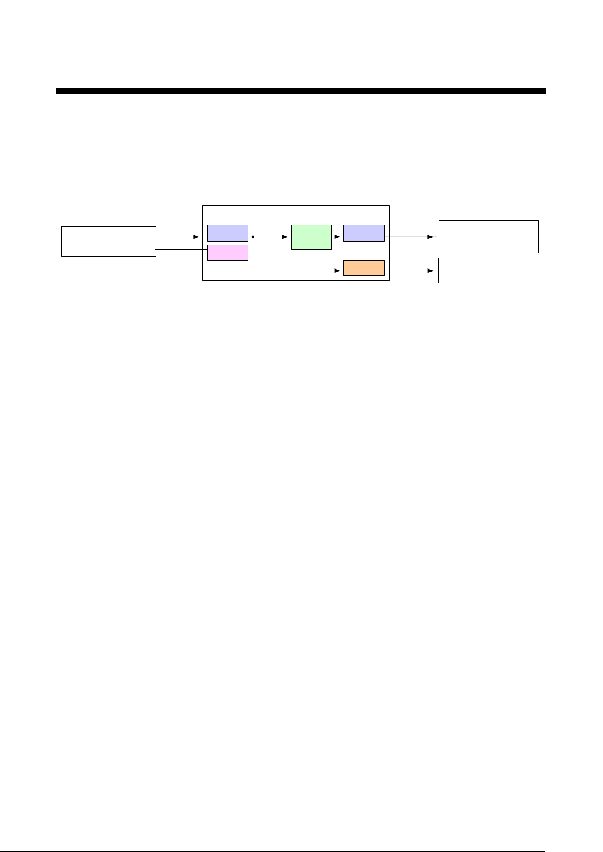
2 Product outline
The VAC-5000HD is an HDMI distribution amplifier for distributing digital video and audio signa ls to 5 outputs.
Since signals can be distributed to multiple devices that hav e the HDMI input connector, the VAC can be used
for multiple systems of HD images, production lines, and others. An L/R stereo audio output is provided, and
only the embedded digital audio input is converted into an analog stereo signal for the stereo analog audio
outputs. The HDMI input has an automatic compen sation circuit while the HDMI output has a manual one,
and they are able to minimize signal degradation caused by cable extension.
[Fig. 2.1] I/O diagram
10

VAC-5000HD User’s Guide
3 Features
Video and audio signals input from the sour ce device can be distributed to multiple sink devices. Audio can be
output as digital or analog signals.
■ Video
● Max. resolution: QWXGA (RB)*
● Digital cable compensation circuit Input and Output: Max.10 m/32.8 feet to 50 m/164.04 feet
● Anti-snow*
2
■ Audio
● Analog audio conversion output
■ Others
● EDID emulation (with copy)
● DDC buffering
● HDCP
● Displaying statues of Input/Output signals
● Connection reset*
3
*1 Only Reduced Blanking is supported.
2
*
The anti-snow feature automatically fixes snow noise that is a specific symptom of HD CP -compliant
signals and mainly occurs at start-up. This feature does not work when snow noise has already occurred
during startup or when it occurs due to a bad condition of the transm ission line.
3
*
For digital systems, some problems, such as an HD CP authentication error, can often be recovered by
physically disconnecting and reconnecti ng the digit al cables. However, the Connection Reset f eature will fix
these problems automatically without the need to physically remove and insert the cables. It creates the
same condition as if the cable were physically disconnected and reconnected. This feature only works for
the VAC’s output. If other devices are connected between the VAC’s output and display devi ce, this feat ure
may be invalid.
1
, 1080p
11
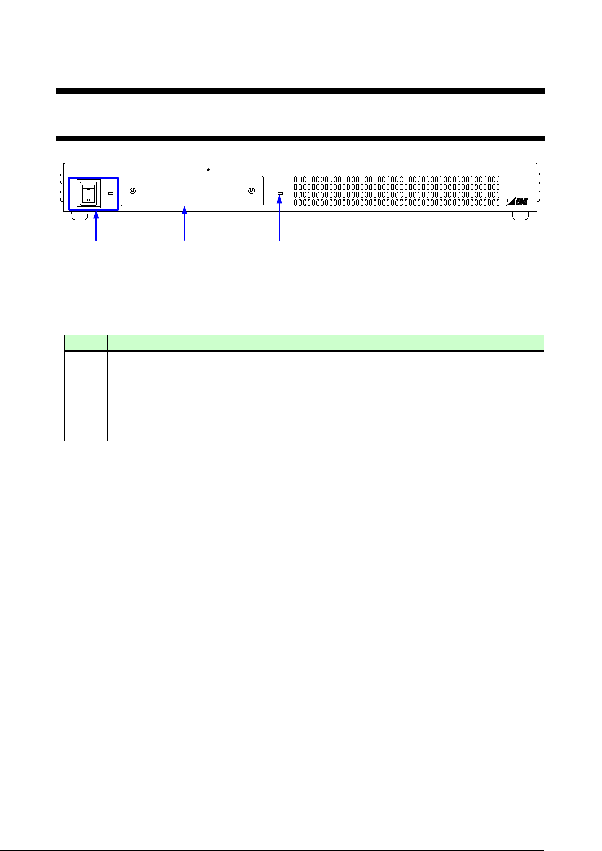
4 Part names and descriptions
ON
OFF
DISTRI BUTI O N AMPLIFIER for HDMI
VAC-5000HD
POWER SIG NAL
①
③
②
#
Part name
Description
POWER switch
Turns on/off the VAC.
menu operation keys
(The cover plate with access to the men is removable.)
4.1 Front panel
[Fig. 4.1] Panel drawing
[Table 4.1] Part names and descriptions
VAC-5000HD User’s Guide
①
②
③
Segment display and
SIGNAL LED The LED lights when vertical synchronizing signals are detected in
The POWER LED lights when the VAC is turned on.
Sets menu using “SET”, “+”, and “-” keys.
the HDMI input connector.
12
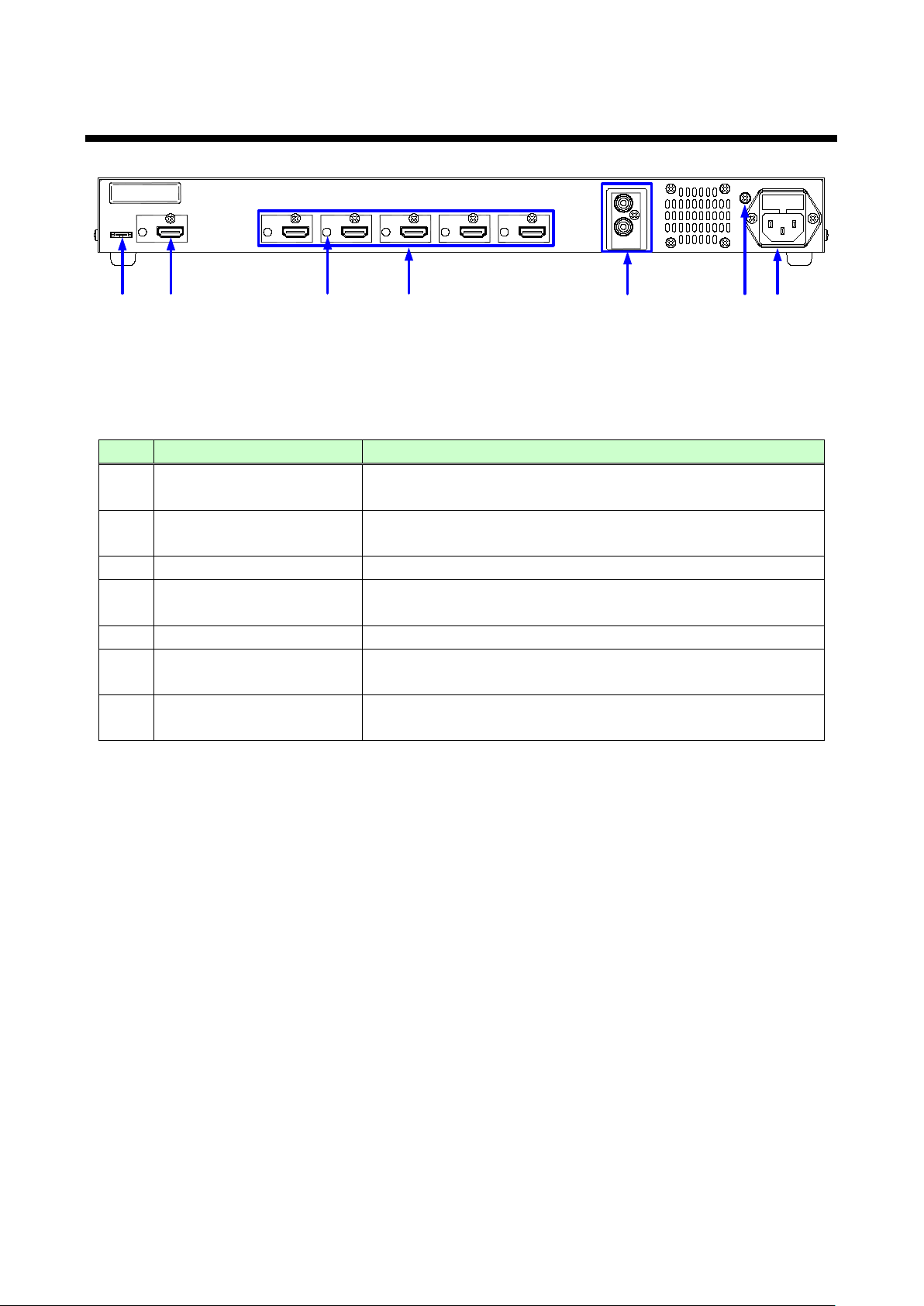
4.2 Rear panel
S/N
AC 100-240V 50/60Hz (FUSE T1A 250V)
UPDATE
FG
OUT 5
OUT 4
OUT 3
OUT 2
OUT 1
ANALOG
AUDIO
R
L
IN
②
①
③
④ ⑤
⑥
⑦
Connector for sink devices such as LCD monitors and projectors
HDMI cable fixing hole
Holes for the supplied cable clamps to fix the HDMI cables
Audio output connector
Analog output for audio of HDMI input signals
Ground for indoor ground terminal
maintenance only.
[Fig. 4.2] Panel drawing
[Table 4.2] Part names and descriptions
# Part name Description
HDMI input connector
①
HDMI output connector
②
Input connector for HDMI signals
Connector for a source device such as a DVD/Blu-ray disc player
Output connector for HDMI signals
VAC-5000HD User’s Guide
③
④
AC adapter connector Connector for the supplied AC adapter
⑤
Frame ground An M3 screw is used.
⑥
Connector for maintenance
⑦
Connector for an amplifier, speaker, mixer, or the like
Not used. Please do not connect anything; this connector is for
13
VAC-5000HD User’s Guide
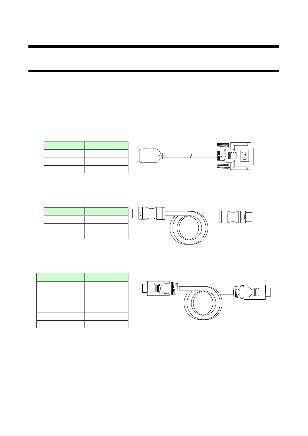
CBL-DH-015A
1.5 m/4.9 feet
CBL-DH-03A
3 m/9.8 feet
CBL-DH-05A
5 m/16.4 feet
Part number
Length
HDSS-10
10 m/32.8 feet
HDSS-15
15 m/49.2 feet
HDSS-20
20 m/65.6 feet
Part number
Length
HDMI/HDMI24-10
10 m/32.8 feet
HDMI/HDMI24-15
15 m/49.2 feet
HDMI/HDMI24-20
20 m/65.6 feet
HDMI/HDMI24-30
30 m/98.4 feet
5 Connecting external devices
5.1 Preparation
Prepare the following cables before connecting ex ternal devices such as source and sink devices.
● HDMI cable (Type A (19-pin) plug, male)
● Stereo cable (RCA pin plug)
■ HDMI cable
[Conversion cable]
For DVI connector, please use one of the following cables.
Part number Length
[Fig. 5.1] Conversion cable (HDMI-DVI conversion)
[Long cable]
If you use 5 m/16.4 feet or longer cable for input/outp ut cable, please use one of the following cables.
[Fig. 5.2] HDMI long cable (Flexible model)
The following cables are also available.
HDMI/HDMI24-40 40 m/131.2 feet
HDMI/HDMI24-50 50 m/164 feet
[Fig. 5.3] HDMI long cable (Standard model)
14
VAC-5000HD User’s Guide
5.2 Precautions before connection
Follow the precautions below before connecting t o external devices.
■ Installation
● Do not block vent holes. Keep enough space (3 cm/1.18 inc hes or more) around the product.
● Do not install the VAC in a closed space.
If you have to install the product to an EIA rack mount in closed space, add a ventilation to keep the
ambient temperature of 40 degrees C/104 degr ees F or less. I f i nadequat ely v ented, the l ife of parts
may be shortened and operations may be af f ect ed.
■ Cabling
● Read the manuals of external devices carefully.
● Turn off the transmitter/receiver before connection.
● Insert the cable into the connector firmly and do not give the connector stress.
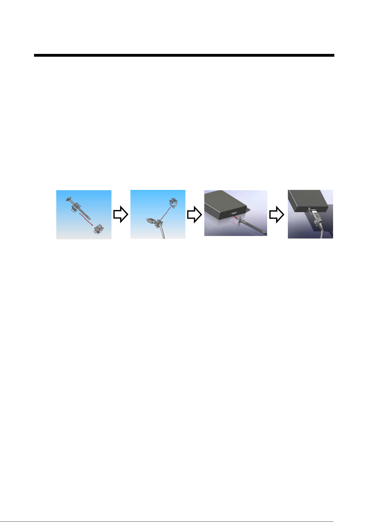
● Secure the HDMI cable using a cable clamp to prevent it from falling out of the device.
[Fig. 5.4] Attaching cable clamp
HDMI cables and connectors do not have a lock me chanism. Use t he supplied ca ble clamp to apply the HDMI
cable to the VAC.
15
 Loading...