

Page 1
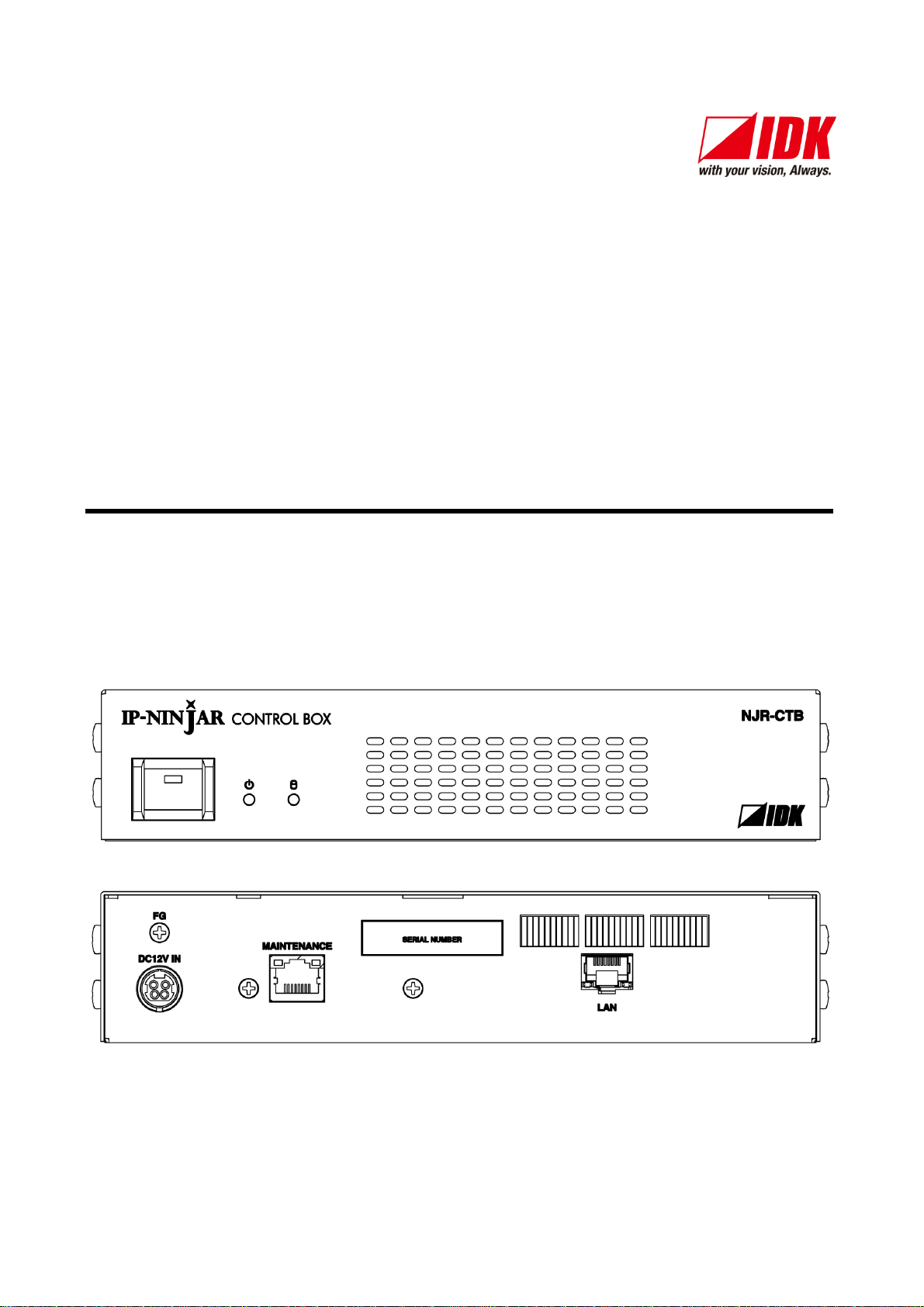
IP-NINJAR Management and Control Box
NJR-CTB
<Command Reference Guide>
Ver.1.1.1
● Thank you for choosing our product.
● To ensure the best performance of this product, please read this Command Guide and Users Guide
fully and carefully before using your product.
IDK Corporation
Page 2

NJR-CTB Command Guide
Trademarks
The terms HDMI and HDMI High-Definition Multimedia Interface, and the HDMI Logo are trademarks or
registered trademarks of HDMI Licensing Administrator, Inc. in the United States and other countries.
Connection Reset and IP-NINJAR are registered trademarks of IDK Corporation in Japan.
All other company and product names mentioned in this manual are either registered trademarks or
trademarks of their respective owners. In this manual, the “®” or “™” marks may not be specified.
2
Page 3

NJR-CTB Command Guide
Before reading this manual
● All rights reserved.
● Some of the contents in this command guide such as product appearance in diagrams, menu operations,
communication commands, and so on may differ from one NJR-CTB model to another.
● This command guide is subject to change without notice. You can download the latest version from IDK’s
website at: http://www.idkav.com
The reference manual for the NJR-CTB consists of the two following volumes:
■ Users guide: Please download from the website above.
■ Command guide (this document): Please download from the website above.
3
Page 4

NJR-CTB Command Guide
Table of Contents
1 How to read this Guide ......................................................................................................................... 5
2 About this Guide ................................................................................................................................... 6
3 Communication configuration and Specifications .................................................................................. 7
3.1 LAN communication ........................................................................................................................ 7
3.1.1 Setup of LAN communication............................................................................................... 7
3.1.2 LAN port specification ................................................................ .......................................... 8
3.1.3 LAN communication specification ........................................................................................ 8
3.1.4 Limit on the number of TCP-IP connections and port overload management ........................ 9
3.2 Connecting LAN cable ....................................................................................................................10
4 Command ...........................................................................................................................................11
4.1 Summary ........................................................................................................................................11
4.2 Command list ................................................................ ................................................................ .12
4.3 Parameter input format ...................................................................................................................14
4.4 Details of commands ................................ ................................................................ ......................15
4.4.1 Error status ................................ ................................................................ .............................15
4.4.2 Basic settings ..........................................................................................................................16
4.4.2.1 Setting channel information .............................................................................................16
4.4.2.2 Setting video ...................................................................................................................17
4.4.2.3 Setting audio ...................................................................................................................19
4.4.2.4 Setting EDID ...................................................................................................................20
4.4.3 Setting transmission ................................................................................................................21
4.4.3.1 Video and audio ..............................................................................................................21
4.4.4 Switching channel ...................................................................................................................25
4.4.4.1 Video and Audio ..............................................................................................................25
4.4.4.2 RS-232C .........................................................................................................................28
4.4.5 Setting communication interface values ...................................................................................29
4.4.5.1 Setting RS-232C .............................................................................................................29
4.4.5.2 CTB LAN settings............................................................................................................30
4.4.6 Maintenance ...........................................................................................................................32
4.4.6.1 CTB version querry .........................................................................................................32
4.4.6.2 Initialization and Reboot ..................................................................................................32
4
Page 5
NJR-CTB Command Guide
IP network
Fiber optic cable
10 GbE switch
Source device
HDMI
NJR-T01UHD (Transmitter)
Source device
HDMI
NJR-T01UHD (Transmitter)
NJR-R01UHD (Receiver)
HDMI
NJR-R01UHD (Receiver)
HDMI
4K supported
monitor
Monitor
PC for control
(For NJR-CTB)
LAN
LAN
Control box (NJR-
CTB)
PC for control
(For communication
command)
RS-232C
PC for control
(For communication
command)
RS-232C
4K@60
video
1080p
video
4K@60
video
1080p
video
Ch.2 to 4
Product outline, Communication setting and specification (Ch.3.2), Command
Ch.2 to 4
Product outline, Communication setting and specification (Ch.3.1), Command
PC for control
(For IP-NINJAR Configurator)
LAN
Model number
User’s guide
Command guide
NJR-T01UHD / NJR-R01UHD
NJR-T01UHD / NJR-R01UHD
User’s guide
NJR-T01UHD / NJR-R01UHD
Command guide
NJR-T04HD / NJR-R04HD
NJR-T04HD / NJR-R04HD
User’s guide
NJR-T04HD / NJR-R04HD
Command guide
NJR-CTB
NJR-CTB
User’s guide
NJR-CTB
Command guide
IP-NINJAR Configurator (for free)
IP-NINJAR Configurator User’s guide
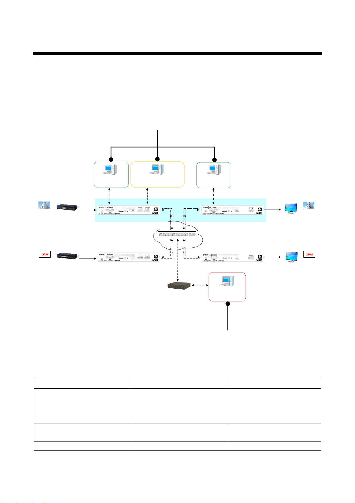
1 How to read this Guide
This guide contains the procedure for using an NJR-CTB Control Box to command IP-NINJAR series
products via LAN communication. The NJR-CTB is for 4K@60 and HDCP2.2 supported HDMI extenders
(NJR-T01UHD, transmitter and NJR-R01UHD, receiver) when usedwith a 10G LAN switch or within an
extended 10G LAN fabric environment*.
*An NJR-CTB is not required for point to point applications where and NJR-T01UHD is connected directly to
an NJR-R01UHD.
[Figure 1.1] Document structure
[Table 1.1] Documents for IP-NINJAR products
5
Page 6

NJR-CTB Command Guide
2 About this Guide
This guide explains how to control the NJR-CTB using commands through LAN communication.
■ Communication commands enables the following main operations:
・Setting input, output, and audio
・Displaying information
・Switching channels
・Loading and setting crosspoint preset
・Loading and setting video wall
6
Page 7
NJR-CTB Command Guide
MAINTENANCE port
Tablet
MAINTENANCE
NJR-CTB
PC for control
Step(1)
LAN cable
*2
Step(3)
Communication
command
TCP:1100
Command
server
WEB
Server
Browser
HTTP:80
LAN
LAN port
HUB
LAN cable
*1
10 GbE switch
Step(2)
Fiber optic cable
LAN port
NJR-T01UHD (Transmitter) or NJR-R01UHD (Receiver)NJR-CTB
NJR-T01UHD (Transmitter)
The LAN port of NJR-CTB should be connected to the LAN port of NJR-T01UHD / NJR-R01UHD or the 10 GbE switch.
※1
PC for control should be connected to the MAINTENANCE port of NJR-CTB or the LAN port of NJR-T01UHD/NJR-R01UHD.
※2
NJR-T01UHD (Transmitter)
NJR-R01UHD (Receiver)
NJR-R01UHD (Receiver)
Fiber optic cable
3 Communication configuration and Specifications
3.1 LAN communication
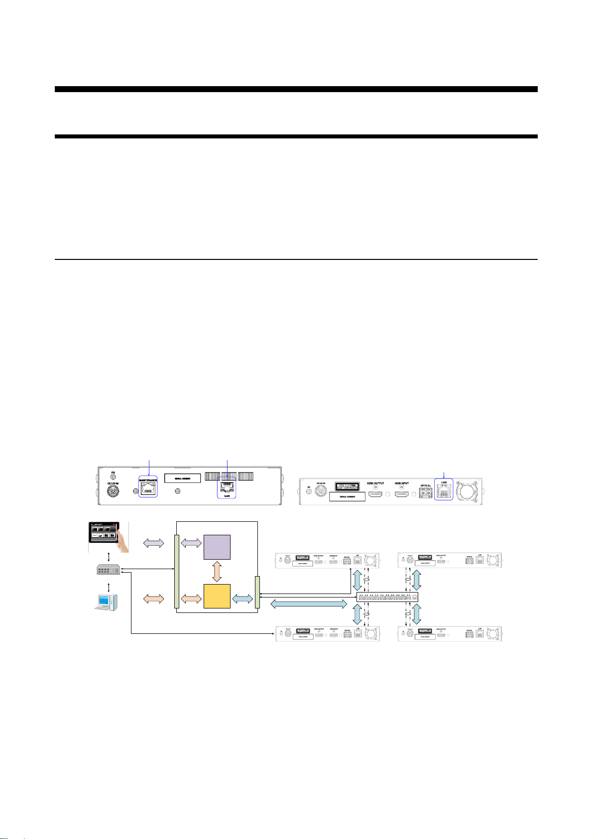
The NJR-CTB can be accessed and controlled through LAN communication.
Connecting a control device to the NJR-CTB’s LAN port enables system control and status querries per the
Command List.
Information:
The NJR-CTB can also be controlled from the WEB browser. Refer to “NJR-CTB User’s Guide” for details.
3.1.1 Setup of LAN communication
Follow the procedure below.
(1) Connect the control device to the MAINTENANCE port of NJR-CTB or LAN port of NJR-T01UHD /
NJR-R01UHD through a LAN cable.
(2) Factory default values of LAN communication are as follows.
IP address: 192.168.1.199
Subnet mask: 255.255.255.0
Default gateway: 192.168.1.200
Establish the connection from the control device to the TCP port number 1100.
(3) Send communication command from the control device to the NJR-CTB.
You can control the NJR-CTB or NJR-T01UHD / NJR-R01UHD and get the status information using
communication command.
[Figure 3.1] LAN communication setup
7
Page 8
NJR-CTB Command Guide
18
8-pin RJ-45 module
connector
Physical layer
10Base-T (IEEE802.3i)/100Base-TX (IEEE802.3u)/1000Base-T (IEEE802.3ab)
Network layer
ARP, IP, ICMP
Transport layer
TCP
Port used for command control: 1100
Port used for WEB browser control (HTTP): 80
Application layer
HTTP
Pin
number
Signal name
MDI
MDI-X
1000BASE-T
100BASE-TX/10BASE-
T
1000BASE-T
100BASE-TX/10BAS
E-T
1
TRX+ (Transmitted/Received
data+)
TX+ (Transmitted
data+)
TRX+ (Transmitted/Received
data+)
RX+ (Received
data+)
2
TRX- (Transmitted/Received
data-)
TX- (Transmitted
data-)
TRX- (Transmitted/Received
data-)
RX- (Received data-)
3
TRX+ (Transmitted/Received
data+)
RX+ (Received data+)
TRX+ (Transmitted/Received
data+)
TX+ (Transmitted
data+)
4
TRX+ (Transmitted/Received
data+)
N.C. (No Connection)
TRX+ (Transmitted/Received
data+)
N.C. (No Connection)
5
TRX- (Transmitted/Received
data-)
N.C. (No Connection)
TRX- (Transmitted/Received
data-)
N.C. (No Connection)
6
TRX- (Transmitted/Received
data-)
RX- (Received data-)
TRX- (Transmitted/Received
data-)
TX- (Transmitted
data-)
7
TRX+ (Transmitted/Received
data+)
N.C. (No Connection)
TRX+ (Transmitted/Received
data+)
N.C. (No Connection)
8
TRX- (Transmitted/Received
data-)
N.C. (No Connection)
TRX- (Transmitted/Received
data-)
N.C. (No Connection)
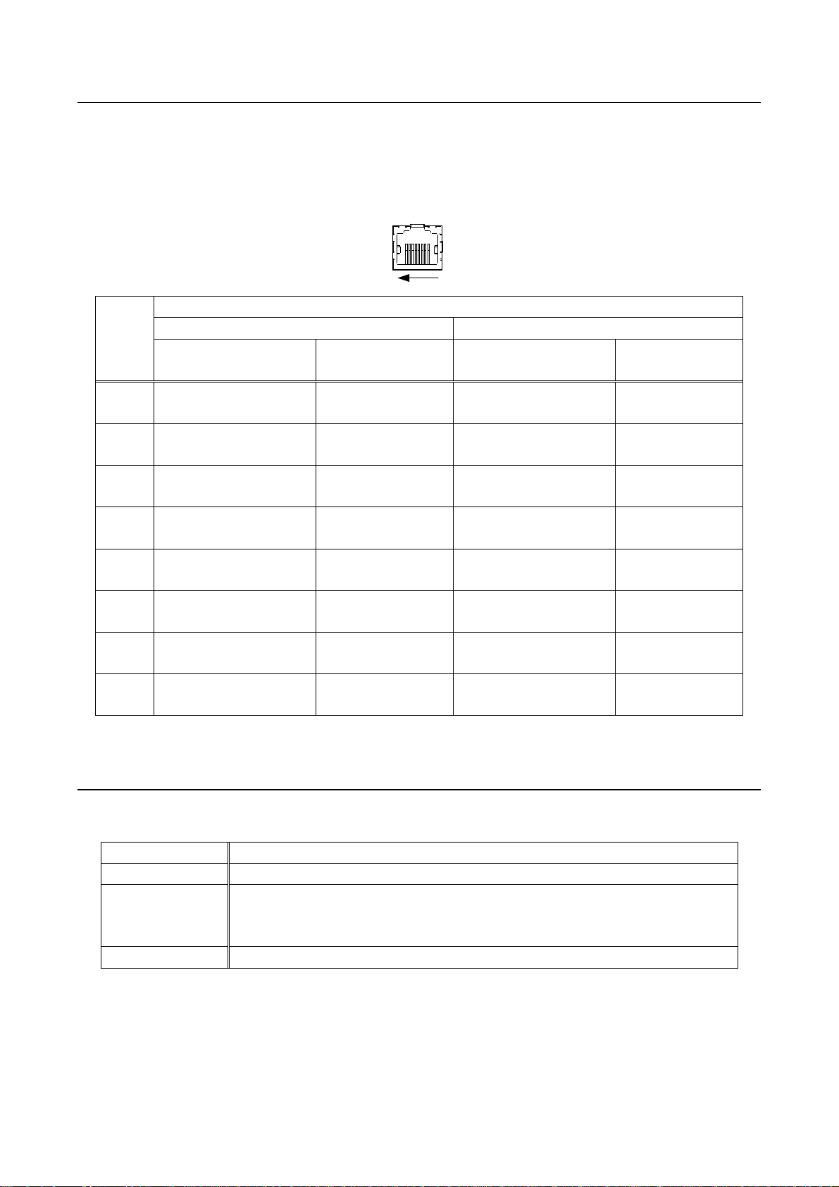
3.1.2 LAN port specification
LAN and MAINTENANCE port assignments are as follows.
Since Auto MDI / MDI-X that distinguishes and switches straight/cross cables automatically is supported,
extra care is not necessary to connect the NJR-CTB to PC, HUB or the like.
[Figure 3.2] LAN / MAINTENANCE port
3.1.3 LAN communication specification
[Table 3.1] LAN communication
Note: Up to 8 connections can be used simultaneously for command control.
8
Page 9
NJR-CTB Command Guide
Your PC software
NJR-CTB
Connecting TCP-IP
→
(Occupying 1 port)
Sending command (@xxx)
→
← Replying command (@xxx)
Closing TCP-IP
→
(Releasing 1port)
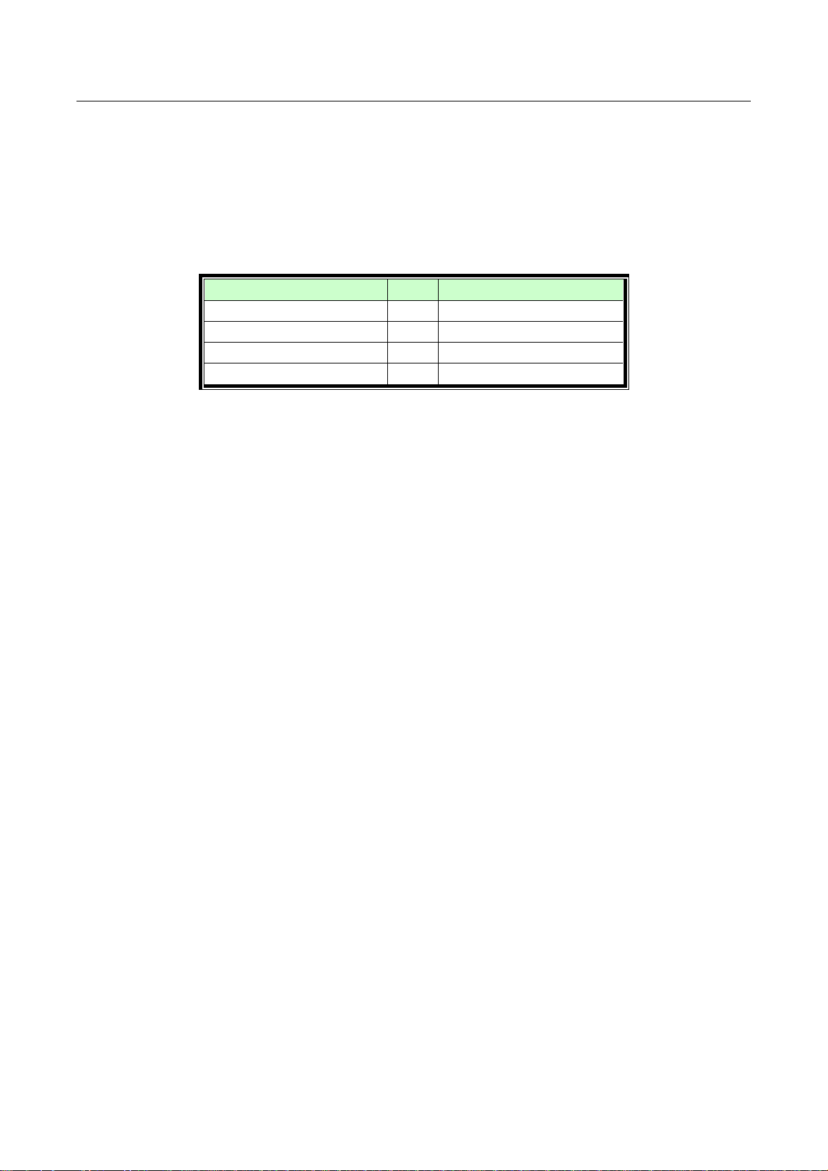
3.1.4 Limit on the number of TCP-IP connections and port overload management
The NJR-CTB’s maintenance port supports a maximum of eight simultaneous connections (eight logical
ports). To maintain optimal system accessibility, it is advisable to issue “port-open” and “port-close”
commands before and after command or query strings are issured. This approach enables eight or more
control devices to be effectively interfaced simultaneously and without concern for communication errors. As a
safeguard, the NJR-CTB incorporates a 30-second timeout window for each port. If any port is inactive for
more than 30 seconds, it will be closed automatically.
[Table 3.2] Increasing connections
Note:
If no command is sent from the PC side to the NJR-CTB for 30 seconds, the NJR-CTB automatically
disconnects from that device.
9
Page 10

NJR-CTB Command Guide
3.2 Connecting LAN cable
The NJR-T01UHD and NJR-R01UHD send broadcast packets through the 10G LAN ports periodically for the
purposes of internal system management. If the 10G LAN port is connected to an existing network, it may
cause a broadcast storm* and may severely interefere with normal network operation. Contact IDK before
attempting to connect the 10G LAN ports of an IP-NINJAR syetem to any existing network infrastructure.
*A broadcast storm occurs when a network is overwhelmed by continuous broadcast traffic resulting in a
network meltdown.
During installation, it is important to avoid the creation of network loops. Contact IDK if you require assistance
with network implementation.
10
Page 11

NJR-CTB Command Guide
4 Command
4.1 Summary
A command consists of “@” (“40” in hexadecimal), 3 or 4 one-byte alphabetical characters (upper and lower
cases) followed by parameters (one-byte numbers). For some commands, multiple parameter values can be
specified. Processing is executed by sending a delimiter at the end of the command.
Example: @RCPP,0,0,1,1
“,”(a comma, “2C” in hex) is indicated between a command and parameter and between two parameters.
“ ” is indicated as a delimiter CR LF (return+line feed, “0D” and “0A” in hex).
■ If an error occurs:
An error response is returned if an undefined command or inappropriate parameter is included.
Example: @RCPP,0
@ERR,1
11
Page 12
NJR-CTB Command Guide
Command
Function
Page
@ERR
Error status
15
Command
Function
Page
@GCHI / @SCHI
Channel
16
Command
Function
Page
@GVOS / @SVOS
Output video
17
Command
Function
Page
@GAOS / @SAOS
Output audio
19
Command
Function
Page
@RMEC
Copying EDID
20
Command
Function
Page
@GWDS / @SWDS
Video and audio transmission
21
@GVDS / @SVDS
Video
22
@GADS / @SADS
Audio transmission
23
@GNDS / @SNDS
Analog audio
24
Command
Function
Page
@GSW / @SSW
Switching video and audio channel simultaneously
25
@GSV / @SSV
Switching video channel
26
@GSA / @SSA
Switching audio channel
26
@GSAA / @SSAA
Switching analog audio channel
27
@GSWR / @SSWR
Switching RS-232Cchannel
28
Command
Function
Page
@GSWR / @SSWR
Switching RS-232Cchannel
28
Command
Function
Page
@GIPS / @SIPS
Setting
30
@GMCC
MAC address
31
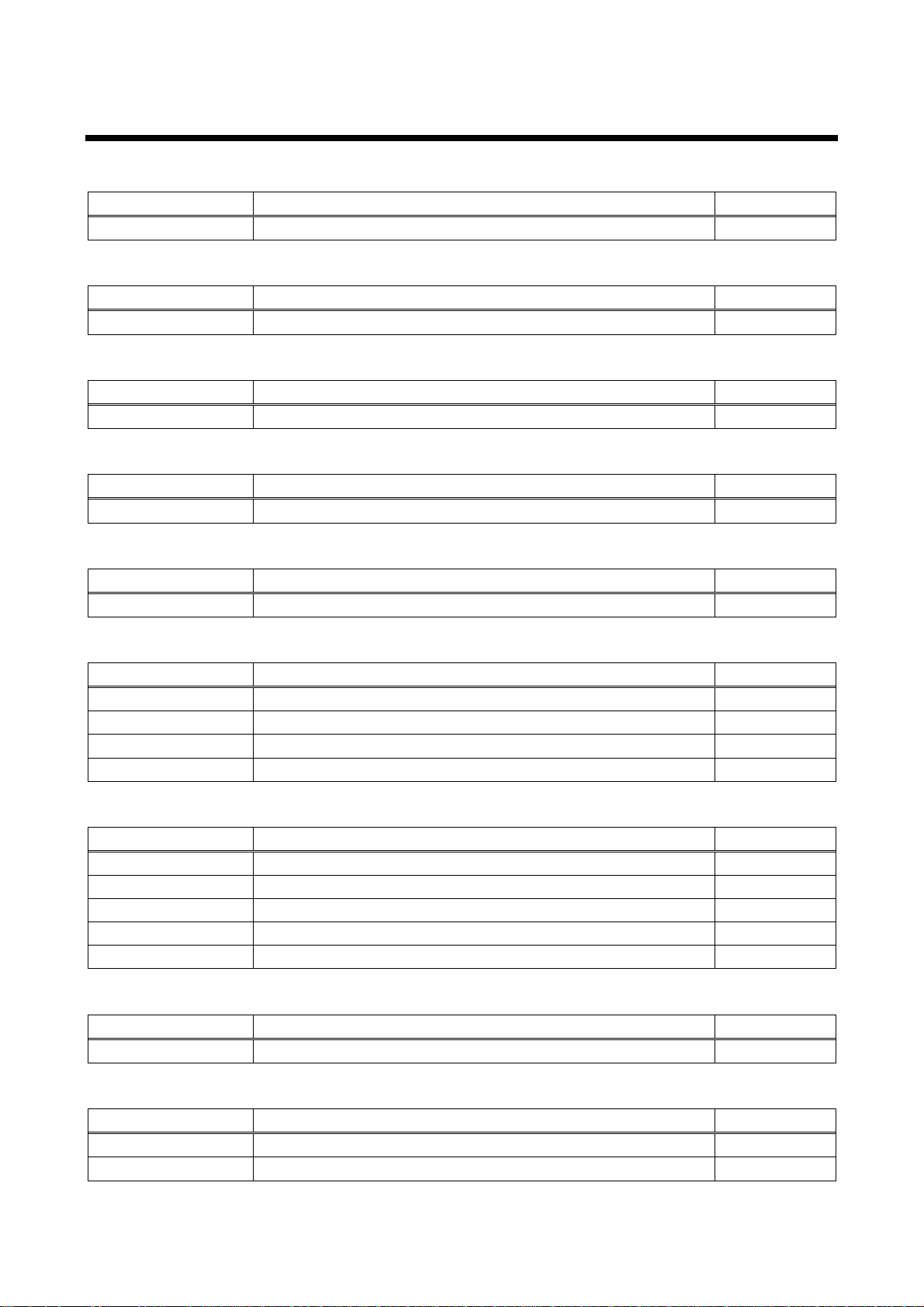
4.2 Command list
■ Error status
■ Setting channel information
■ Setting video
■ Setting audio
■ Setting EDID
■ Video and audio
■ Setting
■ RS-232C
■ CTB LAN
12
Page 13

■ Maintenance
Command
Function
Page
@GIVC
Version
32
@CLRC
Initializing setting
32
@RBTC
Reboot
33
NJR-CTB Command Guide
13
Page 14
NJR-CTB Command Guide
Format
@SAM, device, ch, port, mute
Parameter
device: Model type
1 = NJR-T01UHD, 2 = NJR-R01UHD
ch: Channel
1 to 512 = Channel1 to Channel512
If a command is input from the RS-232C port of NJR-T01UHD/NJR-R01UHD or
from IP-NINJAR Configurator (Software for setting IP-NINJAR) through LAN, the
value is “1” (static).
port: Connector
“1” (static)
mute: Audio mute
0 = Mute OFF [Default], 1 = Mute ON
10 GbE switch
LAN cable
Fiber optic cable
@SAM,1,64,1,1
PC for control
NJR-T01UHD (Transmitter)
NJR-R01UHD (Receiver)
Input channel1
LAN cable
NJR-T01UHD (Transmitter)
NJR-R01UHD (Receiver)
Input channel64
Output channel1
Output channel64
@SAM,2,1,1,1
NJR-CTB
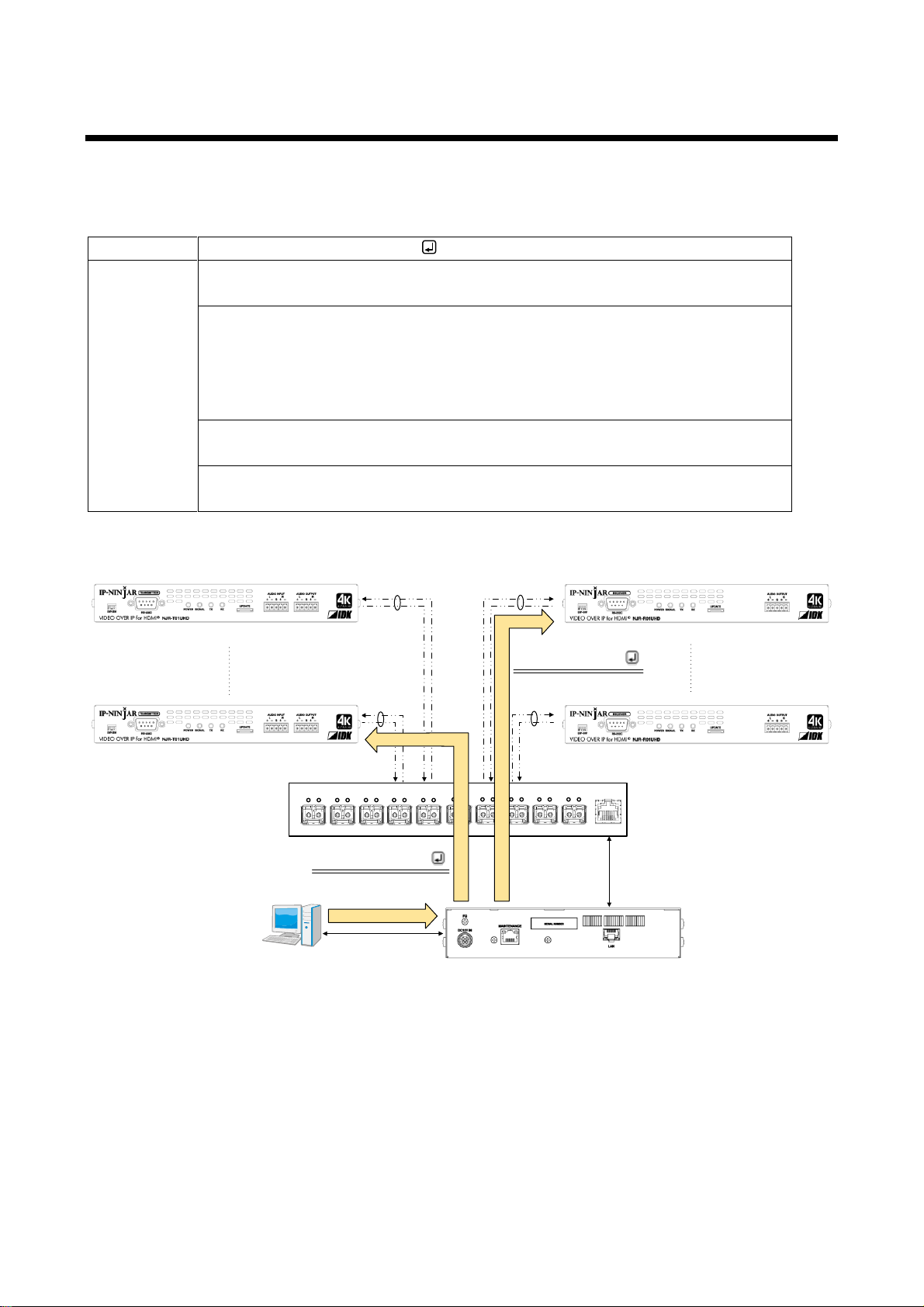
4.3 Parameter input format
Specify the target channel in order to control multiple NJR-T01UHDs and NJR-R01UHDs connected through
a network switch.
Example: The command for setting mute of digital audio output
[Figure 4.1] Command input from NJR-CTB
14
Page 15
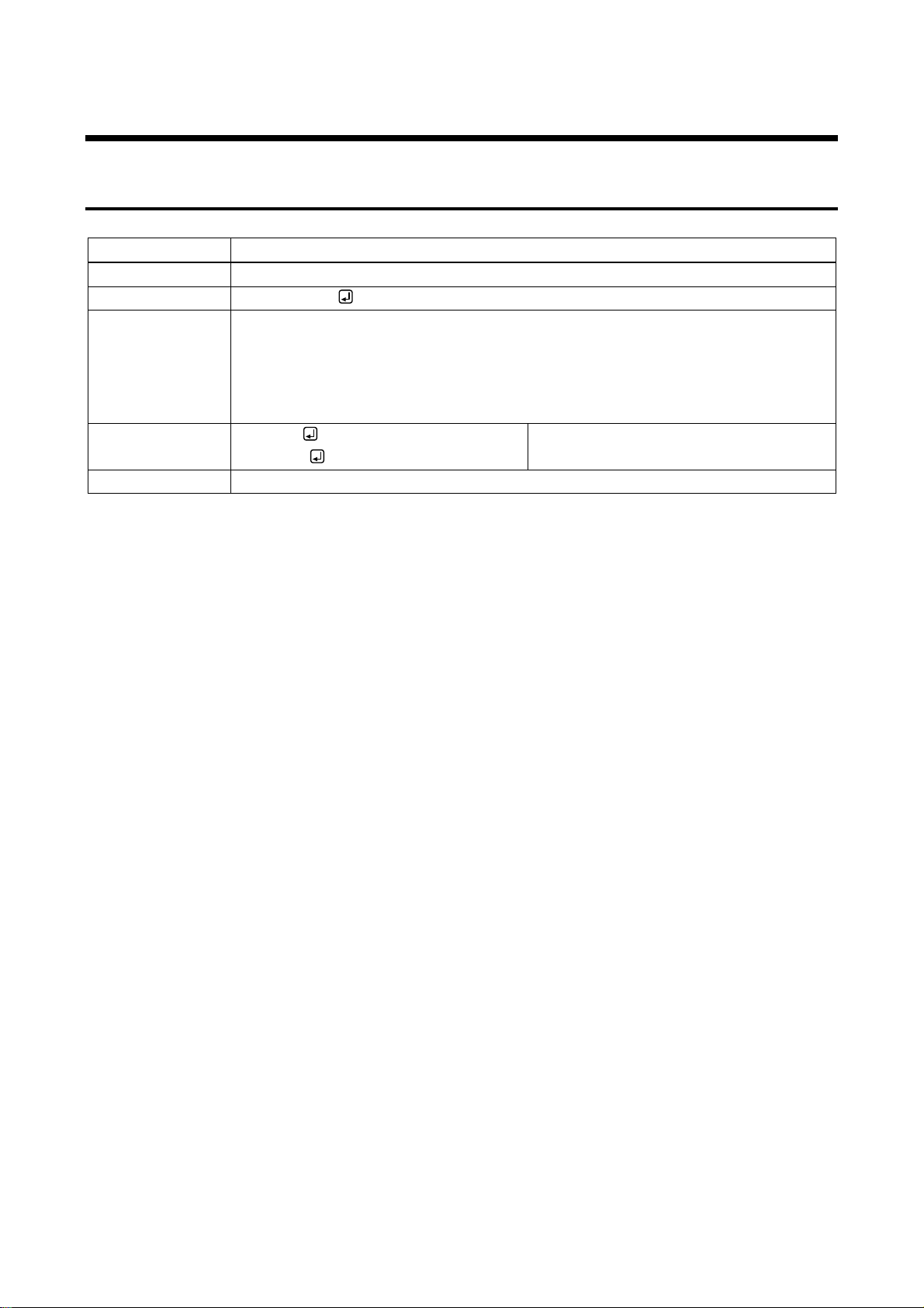
4.4 Details of commands
@ERR
Error status
Format
Return value only
Return value
@ERR, error
Parameter
error: Error status
1 = Erroneous parameter format or value
2 = Undefined command or wrong format
3 = Currently cannot be used.
99 = Error other than errors above
Example
@GCHI
@ERR,1
Sending @GCHI command.
Parameter error
Remarks
-
4.4.1 Error status
NJR-CTB Command Guide
15
Page 16
NJR-CTB Command Guide
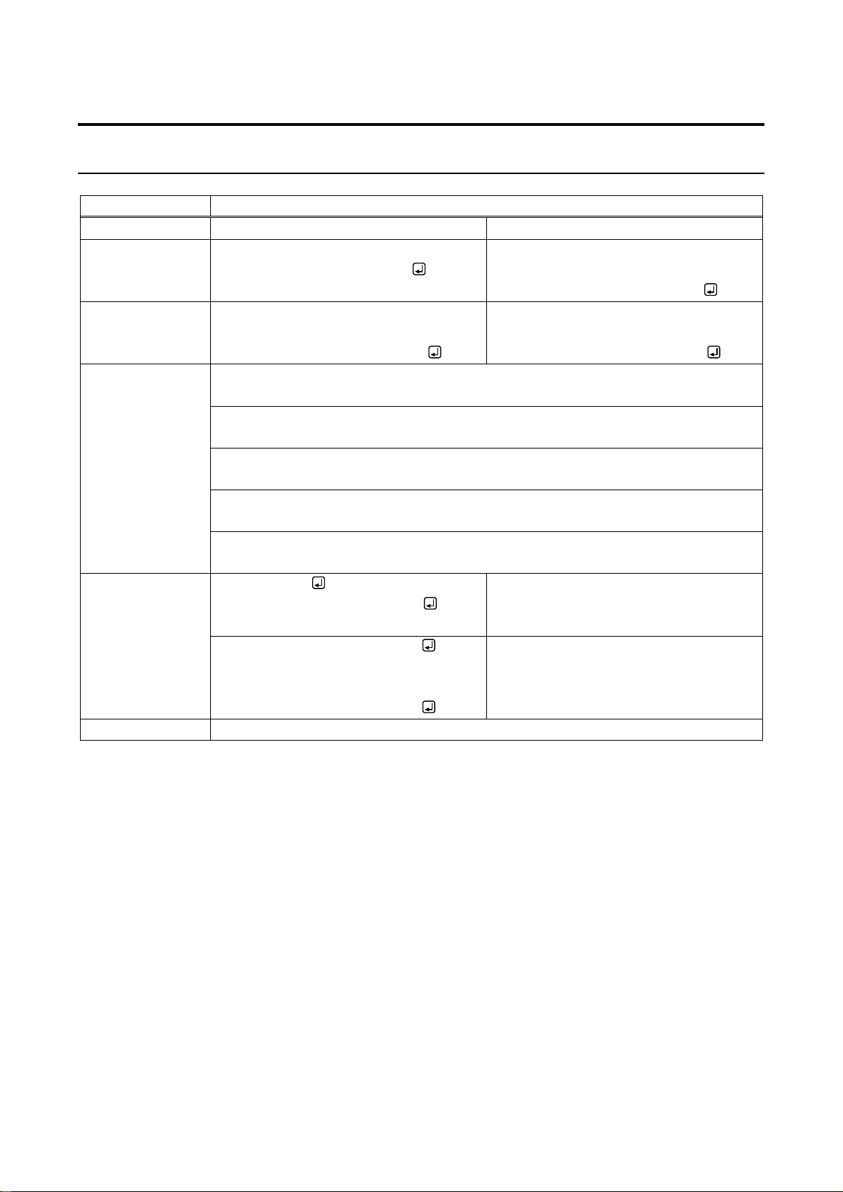
@GCHI / @SCHI
Channel information
Function
Getting
Setting
Format
@GCHI, type_1, ch_1, reserved_1 (,
type_2, ch_2, reserved_2・・・)
@SCHI, type_1, ch_1, reserved_1,
mac_1, hdmi_1 (, type_2, ch_2,
reserved_2, mac_2, hdmi_2・・・)
Return value
@GCHI, type_1, ch_1, reserved_1,
mac_1, hdmi_1 (, type_2, ch_2,
reserved_2, mac_2, hdmi_2・・・)
@SCHI, type_1, ch_1, reserved_1,
mac_1, hdmi_1 (, type_2, ch_2,
reserved_2, mac_2, hidmi_2・・・)
Parameter
type_1 to type_512: Type
1 = Input, 2 = Output
ch_1 to ch_512: Channel
1 to 512 = Channel1 to Channel512
reserved_1 to reserved_512: Reservation
“1” fixed
mac_1 to mac_512: MAC address
00 to FF = 8 bit (in hex) × 6 combinations
hdmi_1 to hdmi_512:HDMI
0 = All connectors, 1 to 4 = Connector1 to 4
Example
@GCHI,1,2,1
@GCHI,1,2,1,0008E5690000,0
Getting information of Input Channel2.
All connectors whose MAC address is
00:08:E5:69:00:00 are assigned.
@SCHI,1,2,1,0008E5690000,0
@SCHI,1,2,1,0008E5690000,0
Assigning all connectors whose MAC
address is 00:08:E5:69:00:00 to Input
Channel2.
Completed normally.
Remarks
-
4.4.2 Basic settings
4.4.2.1 Setting channel information
16
Page 17

4.4.2.2 Setting video
@GVOS /
@SVOS
Output video
Function
Getting
Setting
Format
@GVOS, type_1, ch_1, reserved_1
(, type_2, ch_2, reserved_2・・・)
@SVOS, type_1, ch_1, reserved_1,
mode_1, submode_1, resolution_1
(, type_2, ch_2, reserved_2, mode_2,
submode_2, resolution_2・・・)
Return value
@GVOS, type_1, ch_1, reserved_1,
mode_1, submode_1, resolution_1
(, type_2, ch_2, reserved_2, mode_2,
submode_2, resolution_2・・・)
@SVOS, type_1, ch_1, reserved_1,
mode_1, submode_1, resolution_1
(, type_2, ch_2, reserved_2, mode_2,
submode_2, resolution_2・・・)
Parameter
type_1 to type_512: Type
“2”fixed.
ch_1 to ch_512: Channel
0 = All channels, 1 to 512 = Channel1 to Channel512
reserved_1 to reserved_512: Reservation
“1”fixed.
mode_1 to mode_512: Switching mode
0 = Standard [Default], 1 = Fast & Scaling
submode_1 to submode_512: Sub mode
“0”fixed.
resolution_1 to resolution_512: Resolution
-1 = Not changing previous setting
1 = VGA@60 (640x480),
3 = XGA@60 (1024x768),
5 = WXGA@60 (1280x800),
7 = SXGA@60 (1280x1024),
9 = WXGA@60 (1366x768),
11 = WXGA+@60 (1440x900),
13 = UXGA@60 (1600x1200),
15 = VESAHD@60 (1920x1080),
17 = QWXGA@60 (2048x1152),
19 = WQXGA@60 (2560x1600),
21 = [email protected] (720x480),
24 = 720p@50 (1280x720),
26 = 720p@60 (1280x720),
30 = 1080p@50 (1920x1080),
32 = 1080p@60 (1920x1080),
40 = 2160p@24 (3840x2160),
42 = 2160p@30 (3840x2160),
44 = 2160p@60 (3840x2160),
45 = 2160p@24 (4096x2160),
47 = 2160p@30 (4096x2160),
49 = 2160p@60 (4096x2160)
2 = SVGA@60 (800x600),
4 = WXGA@60 (1280x768),
6 = QuadVGA@60 (1280x960),
8 = WXGA@60 (1360x768),
10 = SXGA+@60 (1400x1050),
12 = WXGA++@60 (1600x900),
14 = WSXGA+@60 (1680x1050),
16 = WUXGA@60 (1920x1200),
18 = WQHD@60 (2560x1440),
23 = 576p@50 (720x576),
25 = [email protected] (1280x720),
31 = [email protected] (1920x1080),
41 = 2160p@25 (3840x2160),
43 = 2160p@50 (3840x2160),
46 = 2160p@25 (4096x2160),
48 = 2160p@50 (4096x2160),
NJR-CTB Command Guide
17
Page 18

NJR-CTB Command Guide
@GVOS /
@SVOS
Output video (Cont’d)
Example
@GVOS,2,1,1
@GVOS,2,1,1,1,0,32
Getting video setting of Ouput Channel1.
Fast & Scaling mode, 1080p@60
@SVOS,2,1,1,1,0,32
@SVOS,2,1,1,1,0,32
Setting video setting of Ouput Channel1
to Fast & Scaling mode 1080p@60.
Completed normally.
Remarks
-
18
Page 19
@GAOS /
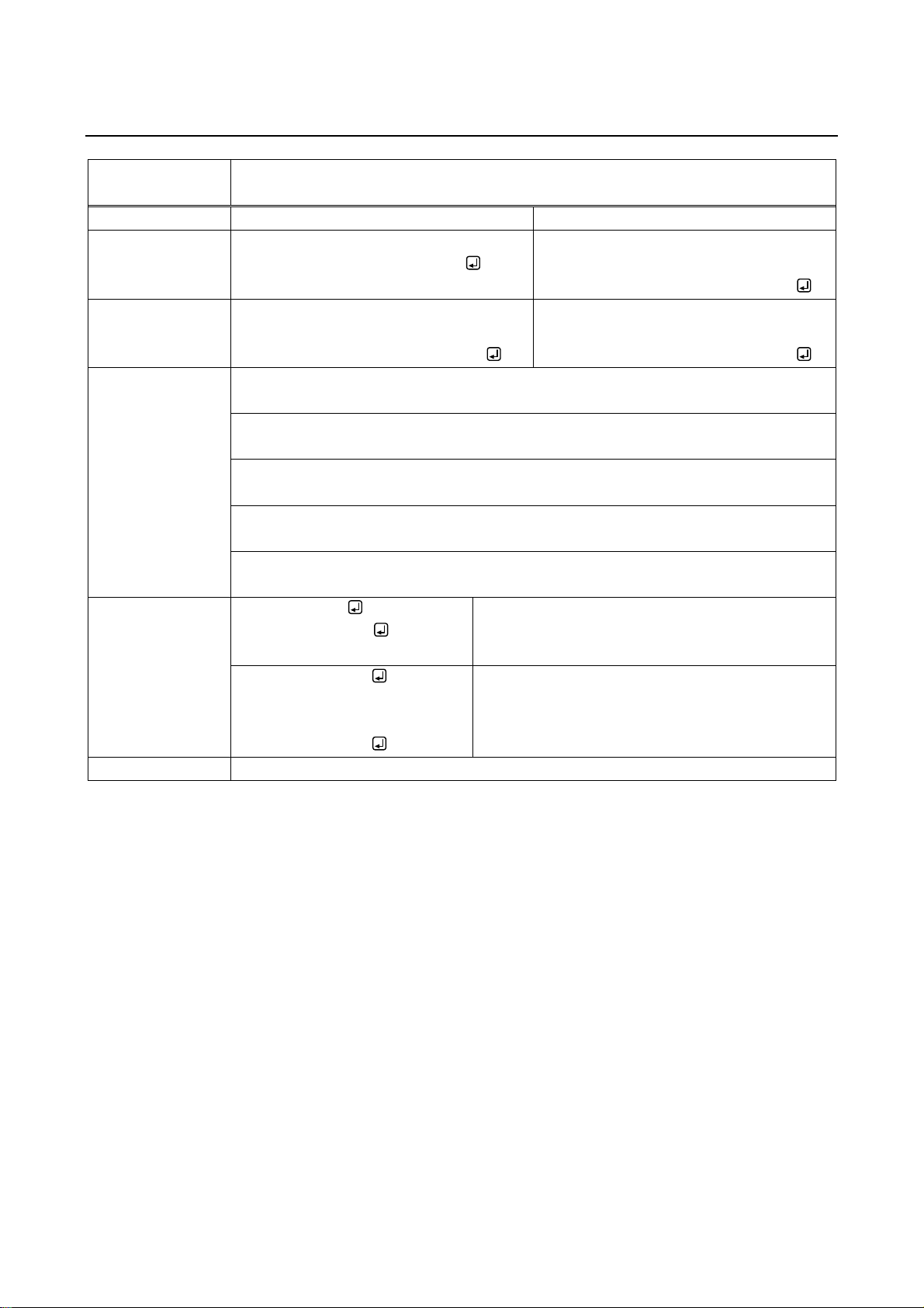
@SAOS
Output audio
Function
Getting
Setting
Format
@GAOS, type_1, ch_1, reserved_1
(, type_2, ch_2, reserved_2・・・)
@SAOS, type_1, ch_1, reserved_1,
analog_1, hdmi_1 (, type_2, ch_2,
reserved_2, analog_2, hdmi_2・・・)
Return value
@GAOS, type_1, ch_1, reserved_1,
analog_1, hdmi_1 (, type_2, ch_2,
reserved_2, analog_2, hdmi_2・・・)
@SAOS, type_1, ch_1, reserved_1,
analog_1, hdmi_1 (, type_2, ch_2,
reserved_2, analog_2, hdmi_2・・・)
Parameter
type_1 to type_512: Type
“2” fixed
ch_1 to ch_512: Channel
0 = All channels, 1 to 512 = Channel1 to Channel512
reserved_1 to reserved_512: Reservation
“1” fixed
hdmi_1 to hdmi_512: HDMI audio ouput
2 = HDMI audio [Default], 3= Analog input audio
analog_1 to analog_512: Audio output connector
2 = HDMI audio, 3= Analog input audio [Default]
Example
@GAOS,2,1,1
@GAOS,2,1,1,2,3
Getting audio setting of Output Channel1.
HDMI audio output: HDMI audio; Audio output
connector: Analog input audio
@SAOS,2,1,1,2,3
@SAOS,2,1,1,2,3
Setting HDMI audio ouput of Output Channel1 to
output analog input audio from HDMI audio output
and audio outout connector.
Completed normally.
Remarks
-
4.4.2.3 Setting audio
NJR-CTB Command Guide
19
Page 20
NJR-CTB Command Guide
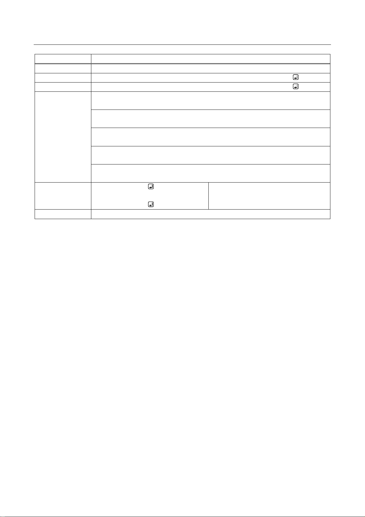
@RMEC
Copying EDID
Function
Getting
Format
@RMEC, type, ch, reserved, input_1, output_1 (, input _2, output_2・・・)
Return value
@RMEC, type, ch, reserved, input_1, output_1 (, input _2, output_2・・・)
Parameter
type: Type
“0”fixed.
ch: Channel
“0”fixed.
reserved: Reservation
“1”fixed.
input_1 to input_512: Input Channel
0 = All inputs, 1 to 512 = Input Channnel1 to Input Channel512
output_1 to output_512: Output Channel
1 to 512 = Output Channel1 to Ouput Channel512
Example
@RMEC,0,0,1,1,2
@RMEC,0,0,1,1,2
Copying Output Channel2’s EDID to Input
Channel1.
Completed normally.
Remarks
-
4.4.2.4 Setting EDID
20
Page 21
4.4.3 Setting transmission
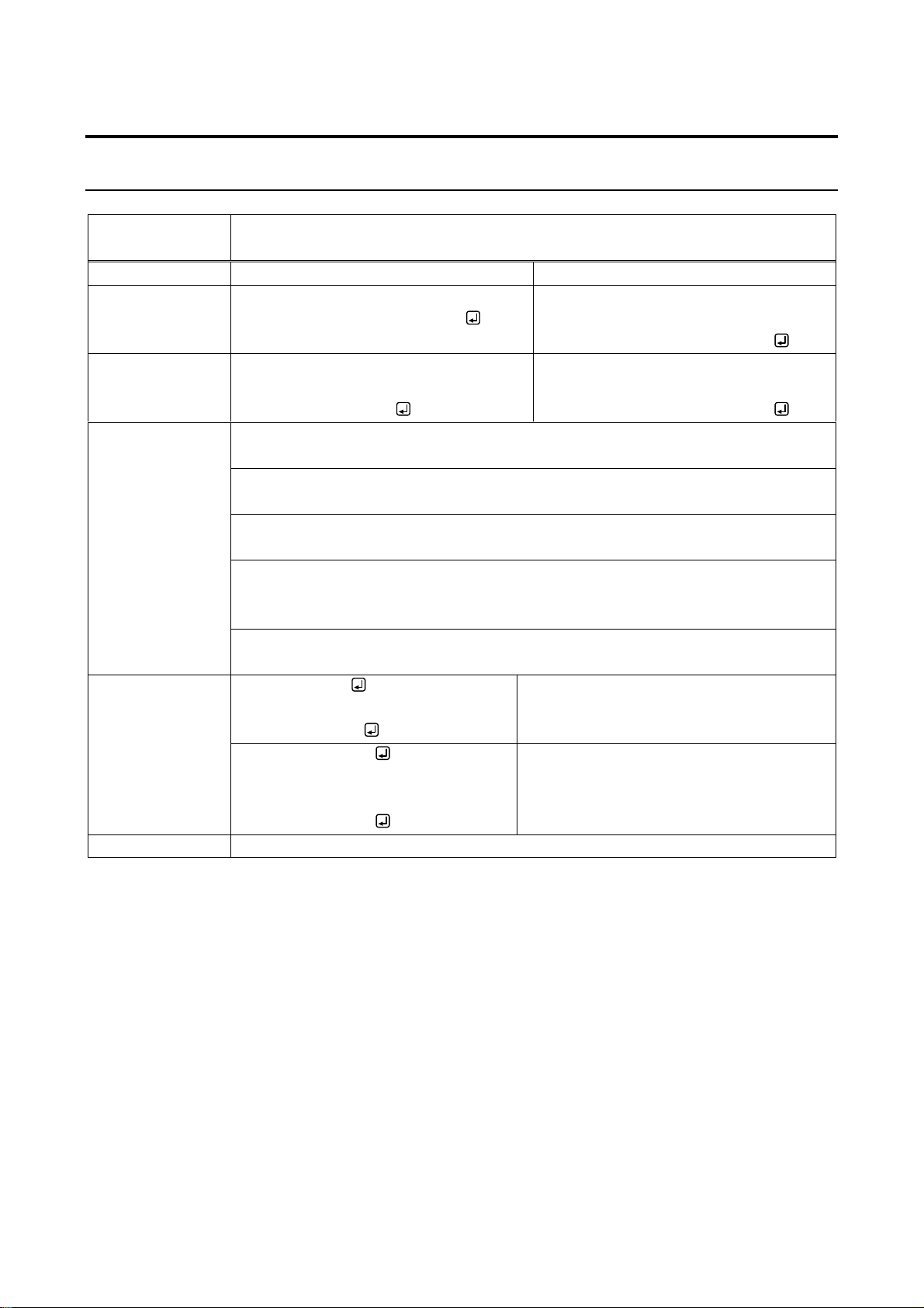
@GWDS /
@SWDS
Video and audio transmission
Function
Getting
Setting
Format
@GWDS, type_1, ch_1, reserved_1
(, type_2, ch_2, reserved_2・・・)
@SWDS, type_1, ch_1, reserved_1,
mode_1, free_1 (, type_2, ch_2,
reserved_2, mode_2, free_2・・・)
Return value
@GWDS, type_1, ch_1, reserved_1,
mode_1 (, type_2, ch_2, reserved_2,
index_2, mode_2・・・)
@SWDS, type_1, ch_1, reserved_1,
mode_1, free_1 (, type_2, ch_2,
reserved_2, mode_2, free_2・・・)
Parameter
type_1 to type_512: Type
1 = Input, 2 = Output
ch_1 to ch_512: Channel
0 = All channels (only for setting), 1 to 512 = Channel1 to Channel512
reserved_1 to reserved_512: Reservation
“0”fixed.
mode_1 to mode_512: Mode
0 = Stop [Default], 1 = Transmit or Receive
For setting output channel, only “0” can be set.
free_1 to free_512: Initialization of transmission address
0 = Disabled [Default], 1 = Enabled
@GWDS,1,1,0
@GWDS,1,1,0,1
Getting video / audio transmission status of
Input Channel1.
Being transmitted.
Example
@SWDS,1,1,0,0,1
@SWDS,1,1,0,0,1
Stopping video / audio transmission of Input
Channel1 and initializing the transmission
address.
Completed normally.
Remarks
For getting, the Ouput Channel is the same for video and audio.
4.4.3.1 Video and audio
NJR-CTB Command Guide
21
Page 22
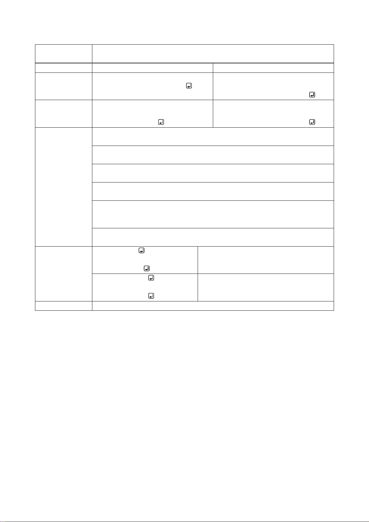
NJR-CTB Command Guide
@GVDS /
@SVDS
Video transmission
Function
Getting
Setting
Format
@GVDS, type_1, ch_1, reserved_1
(, type_2, ch_2, reserved_2・・・)
@SVDS, type_1, ch_1, reserved_1,
mode_1, free_1 (, type_2, ch_2,
reserved_2, mode_2, free_2・・・)
Return value
@GVDS, type_1, ch_1, reserved_1,
mode_1 (, type_2, ch_2, reserved_2,
index_2, mode_2・・・)
@SVDS, type_1, ch_1, reserved_1,
mode_1, free_1 (, type_2, ch_2,
reserved_2, mode_2, free_2・・・)
Parameter
type_1 to type_512: Type
1 = Input, 2 = Output
ch_1 to ch_512: Channel
0 = All channels (only for setting), 1 to 512 = Channel1 to Channel512
reserved_1 to reserved_512: Reservation
“0” fixed.
index_1 to index_512: Reservation
“0” fixed.
mode_1 to mode_512: Mode
0 = Stop [Default], 1 = Start
Only “0” can be selected for setting output channel
free_1 to free_512: Initializing transmission address
0 = Disabled [Default], 1 = Enabled
Example
@GVDS,1,1,0
@GVDS,1,1,0,1
Getting video transmission status of Input
Channel1.
Being distributed
@SVDS,1,1,0,0,1
@SVDS,1,1,0,0,1
Stopping video transmission of Input channel1
and initializing transmission address.
Completed normally.
Remarks
-
22
Page 23
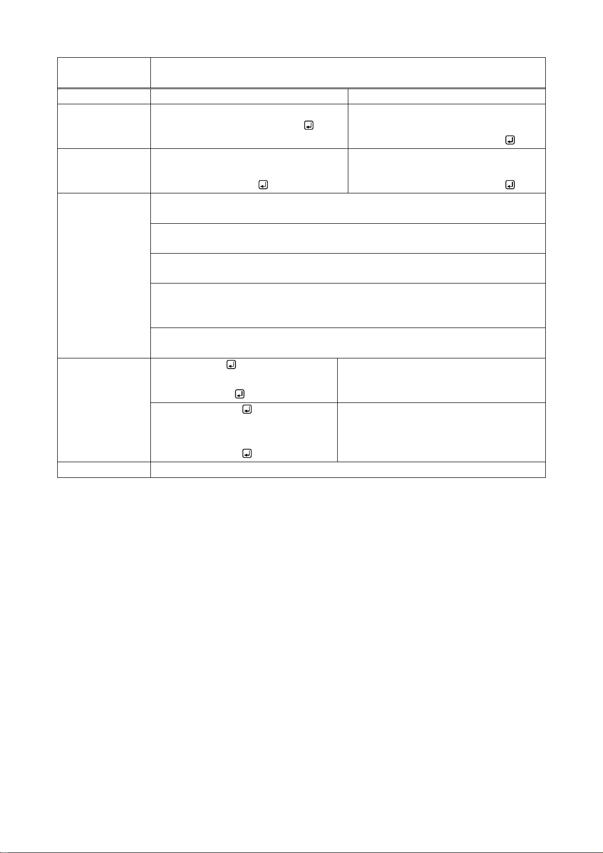
NJR-CTB Command Guide
@GADS /
@SADS
Audio transmission
Function
Getting
Setting
Format
@GADS, type_1, ch_1, reserved_1
(, type_2, ch_2, reserved_2・・・)
@SADS, type_1, ch_1, reserved_1,
mode_1, free_1 (, type_2, ch_2,
reserved_2, mode_2, free_2・・・)
Return value
@GADS, type_1, ch_1, reserved_1,
mode_1 (, type_2, ch_2, reserved_2,
index_2, mode_2・・・)
@SADS, type_1, ch_1, reserved_1,
mode_1, free_1 (, type_2, ch_2,
reserved_2, mode_2, free_2・・・)
Parameter
type_1 to type_512: Type
1 = Input, 2 = Output
ch_1 to ch_512: Channel
0 = All channels (only for setting), 1 to 512 = Channel1 to Channel512
reserved_1 to reserved_512: Reservation
“0”fixed.
mode_1 to mode_512: Mode
0 = Stop [Default], 1 = Transmit or Receive
For setting output channel, only “0” can be set.
free_1 to free_512: Initialization of transmission address
0 = Disabled [Default], 1 = Enabled
Example
@GADS,1,1,0
@GADS,1,1,0,1
Getting audio transmission status of Input
Channel1.
Being transmitted.
@SADS,1,1,0,0,1
@SADS,1,1,0,0,1
Stopping audio transmission of Input
Channel1 and initializing the transmission
address.
Completed normally.
Remarks
-
23
Page 24
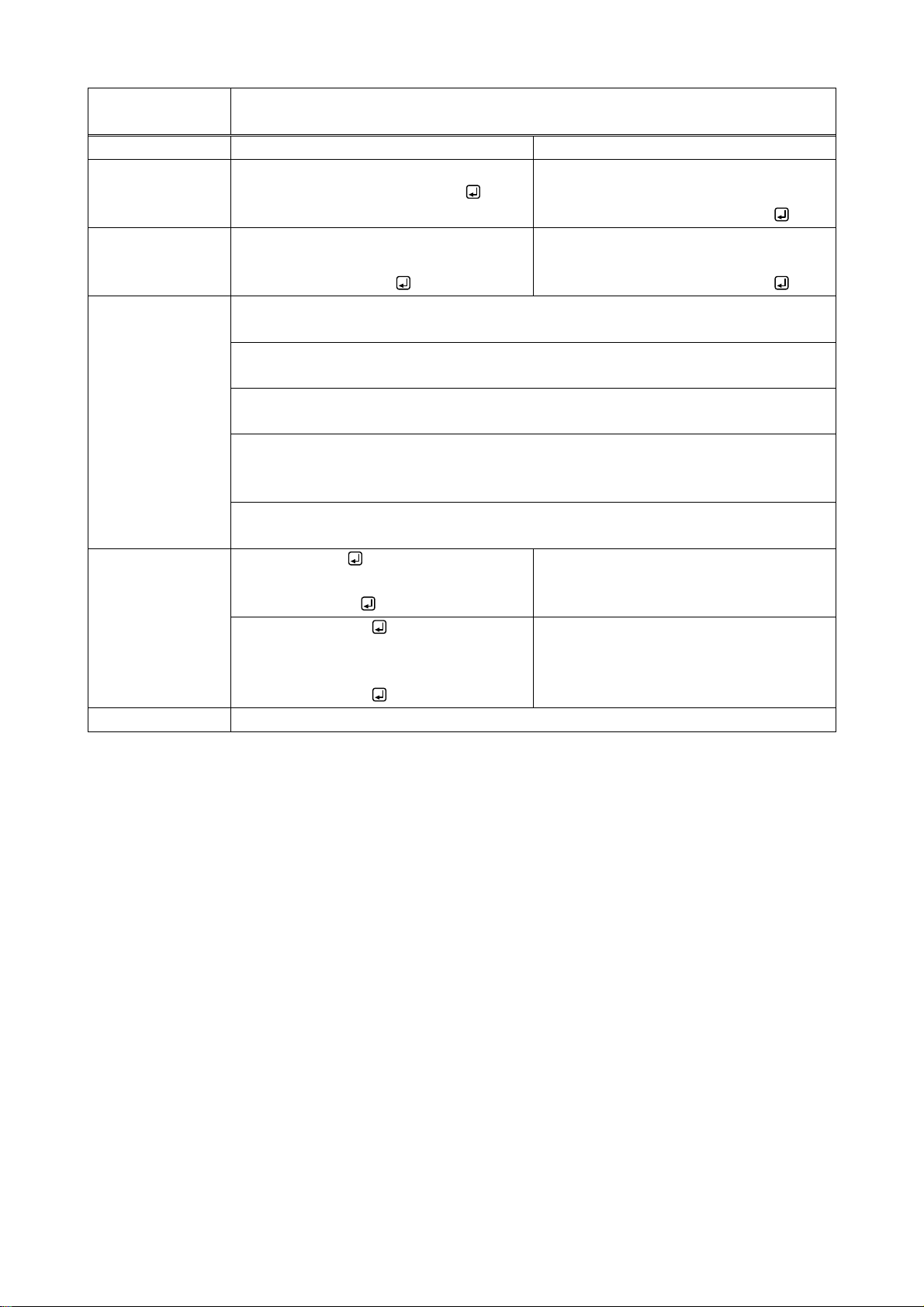
NJR-CTB Command Guide
@GNDS /
@SNDS
Analog audio transmission
Function
Getting
Setting
Format
@GNDS, type_1, ch_1, reserved_1
(, type_2, ch_2, reserved_2・・・)
@SNDS, type_1, ch_1, reserved_1,
mode_1, free_1 (, type_2, ch_2,
reserved_2, mode_2, free_2・・・)
Return value
@GNDS, type_1, ch_1, reserved_1,
mode_1 (, type_2, ch_2, reserved_2,
index_2, mode_2・・・)
@SNDS, type_1, ch_1, reserved_1,
mode_1, free_1 (, type_2, ch_2,
reserved_2, mode_2, free_2・・・)
Parameter
type_1 to type_512: Type
1 = Input, 2 = Output
ch_1 to ch_512: Channel
0 = All channels (only for setting), 1 to 512 = Channel1 to Channel512
reserved_1 to reserved_512: Reservation
“0”fixed.
mode_1 to mode_512: Mode
0 = Stop [Default], 1 = Transmit or Receive
For setting output channel, only “0” can be set.
free_1 to free_512: Initialization of transmission address
0 = Disabled [Default], 1 = Enabled
Example
@GNDS,1,1,0
@GNDS,1,1,0,1
Getting audio transmission status of Input
Channel1.
Being transmitted.
@SNDS,1,1,0,0,1
@SNDS,1,1,0,0,1
Stopping audio transmission of Input
Channel1 and initializing the transmission
address.
Completed normally.
Remarks
-
24
Page 25
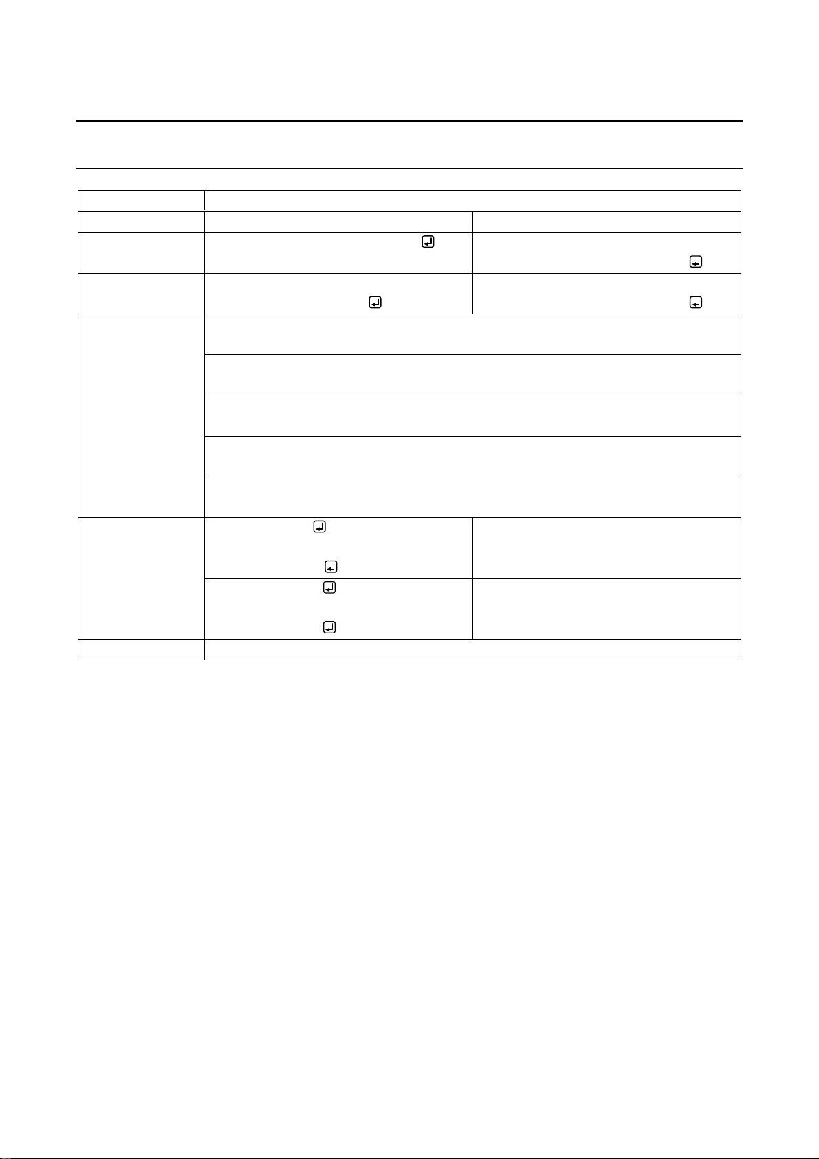
4.4.4 Switching channel
@GSW / @SSW
Switching video and audio channel simultaneously
Function
Getting
Setting
Format
@GSW, type, ch, reserved, input
@SSW, type, ch, reserved, input_1,
output_1 (, input_2, output_2・・・)
Return value
@GSW, type, ch, reserved, input,
output_1 (, output_2・・・)
@SSW, type, ch, reserved, input_1,
output_1 (, input_2, output_2・・・)
Parameter
type: Type
“0” fixed
ch: Channel
“0” fixed
reserved: Reservation
“1” fixed
input: Video and audio input channel
0 = OFF [Default], 1 to 512 = Input channel1 to Input channel512
output_1 to output_512:Video and audio output channel
0 = All outputs, 1 to 512 = Output channel1 to Output channel512
Example
@GSW,0,0,1,1
@GSW,0,0,1,1,2
Getting the Output channel to which video
and audio of Input channel1 are output.
Output channel2.
@SSW,0,0,1,1,2
@SSW,0,0,1,1,2
Outputting video and audio of Input
channel1 to Output channel2.
Completed normally.
Remarks
-
4.4.4.1 Video and Audio
NJR-CTB Command Guide
25
Page 26
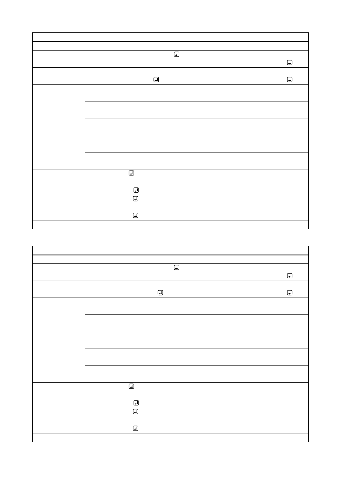
NJR-CTB Command Guide
@GSV / @SSV
Switching video channel
Function
Getting
Setting
Format
@GSV, type, ch, reserved, input
@SSV, type, ch, reserved, input_1,
output_1 (, input_2, output_2・・・)
Return value
@GSV, type, ch, reserved, input,
output_1 (, output_2・・・)
@SSV, type, ch, reserved, input_1,
output_1 (, input_2, output_2・・・)
Parameter
type: Type
“0” fixed
ch: Channel
“0” fixed
reserved: Reservation
“1” fixed
input: Video input channel
0 = OFF [Default], 1 to 512 = Input channel1 to Input channel512
output_1 to output_512: Video output channel
0 = All outputs, 1 to 512 = Output channel1 to Output channel512
Example
@GSV,0,0,1,1
Getting the Output channel to which video
of Input channel1 is output.
Output channel2
@GSV,0,0,1,1,2
@SSV,0,0,1,1,2
@SSV,0,0,1,1,2
Outputting video of Input channel1 to
Output channel2.
Completed normally.
Remarks
-
@GSA / @SSA
Switching audio channel
Function
Getting
Setting
Format
@GSA, type, ch, reserved, input
@SSA, type, ch, reserved, input_1,
output_1 (, input_2, output_2・・・)
Return value
@GSA, type, ch, reserved, input,
output_1 (, output_2・・・)
@SSA, type, ch, reserved, input_1,
output_1 (, input_2, output_2・・・)
Parameter
type: Type
“0” fixed
ch: Channel
“0” fixed
reserved: Reservation
“1” fixed
input: Audio input channel
0 = OFF [Default], 1 to 512 = Input channel1 to Input channel512
output_1 to output_512: Audio output channel
0 = All outputs, 1 to 512 = Output channel1 to Output channel512
Example
@GSA,0,0,1,1
@GSA,0,0,1,1,2
Getting the Output channel to which
audio of Input channel1 is output.
Output channel2
@SSA,0,0,1,1,2
@SSA,0,0,1,1,2
Outputting audio of Input channel1 to
Output channel2.
Completed normally.
Remarks
-
26
Page 27
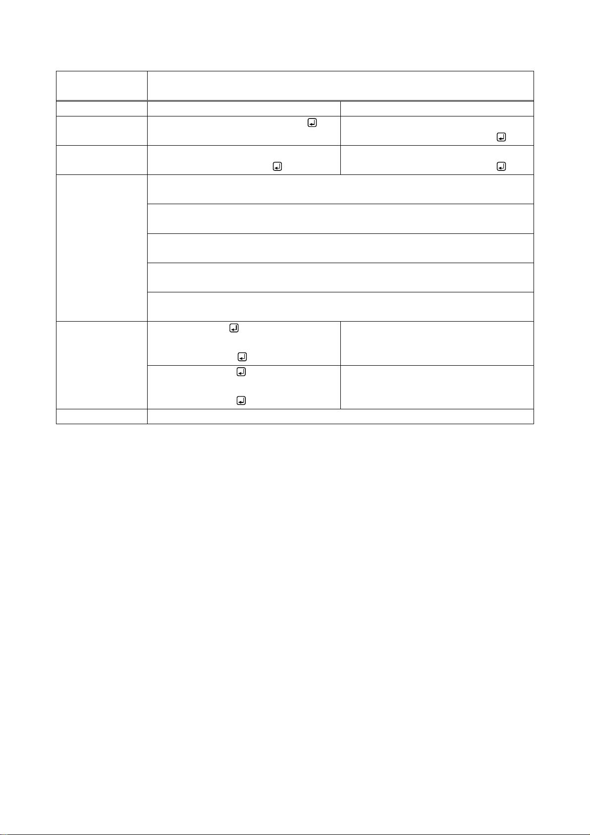
NJR-CTB Command Guide
@GSAA /
@SSAA
Switching analog audio channel
Function
Getting
Setting
Format
@GSAA, type, ch, reserved, input
@SSAA, type, ch, reserved, input_1,
output_1 (, input_2, output_2・・・)
Return value
@GSAA, type, ch, reserved, input,
output_1 (, output_2・・・)
@SSAA, type, ch, reserved, input_1,
output_1 (, input_2, output_2・・・)
Parameter
type: Type
“0” fixed
ch: Channel
“0” fixed
reserved: Reservation
“1” fixed
input: Audio input channel
0 = OFF [Default], 1 to 512 = Input channel1 to Input channel512
output_1 to output_512: Audio output channel
0 = All outputs, 1 to 512 = Output channel1 to Output channel512
Example
@GSAA,0,0,1,1
@GSAA,0,0,1,1,2
Getting the Output channel to which
audio of Input channel1 is output.
Output channel2
@SSAA,0,0,1,1,2
@SSAA,0,0,1,1,2
Outputting audio of Input channel1 to
Output channel2.
Completed normally.
Remarks
-
27
Page 28
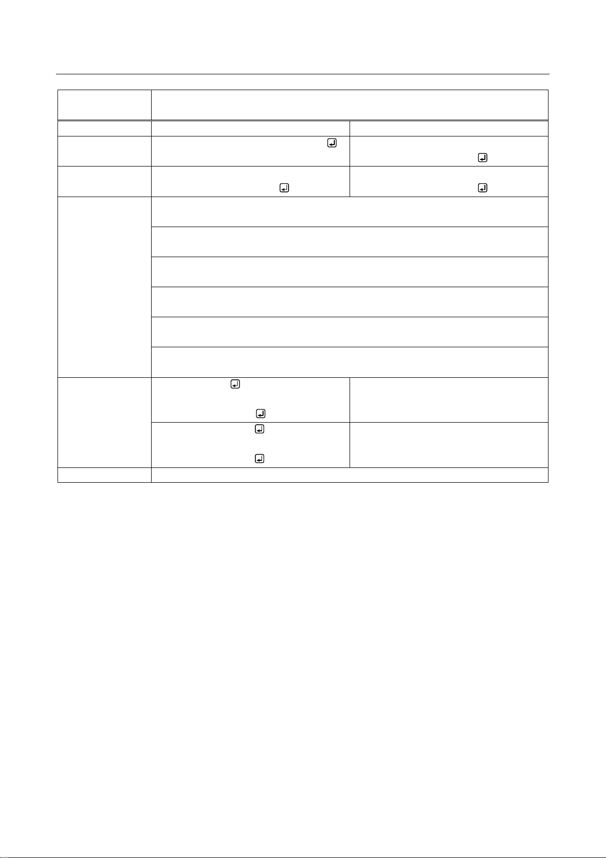
NJR-CTB Command Guide
@GSWR /
@SSWR
Switching RS-232Cchannel
Function
Getting
Setting
Format
@GSWR, src_type, src_ch, src_port
@SSWR, src_type, src_ch, src_port,
dst_type, dst_ch, dst_port
Return value
@GSWR, src_type, src_ch, src_port,
dst_type, dst_ch, dst_port
@SSWR, src_type, src_ch, src_port,
dst_type, dst_ch, dst_port
Parameter
src_type: Source type
1 = Input, 2 = Output
src_ch: Source channel
1 to 512 = Channel1 to Channel512
src_port: Source connector
“1” fixed
dst_type: Destination type
1 = Input, 2 = Output
dst_ch: Destination channel
1 to 512 = Channel1 to Channel512
dst_port: Destination connector
“1” fixed
Example
@GSWR,1,1,1
@GSWR,1,1,1,2,2,1
Getting the channel connected to
RS-232C of Input channel1.
Output channel2
@SSWR,1,1,1,2,2,1
@SSWR,1,1,1,2,2,1
Connecting Input channel1 and RS-232C
of channel2.
Completed normally.
Remarks
-
4.4.4.2 RS-232C
28
Page 29
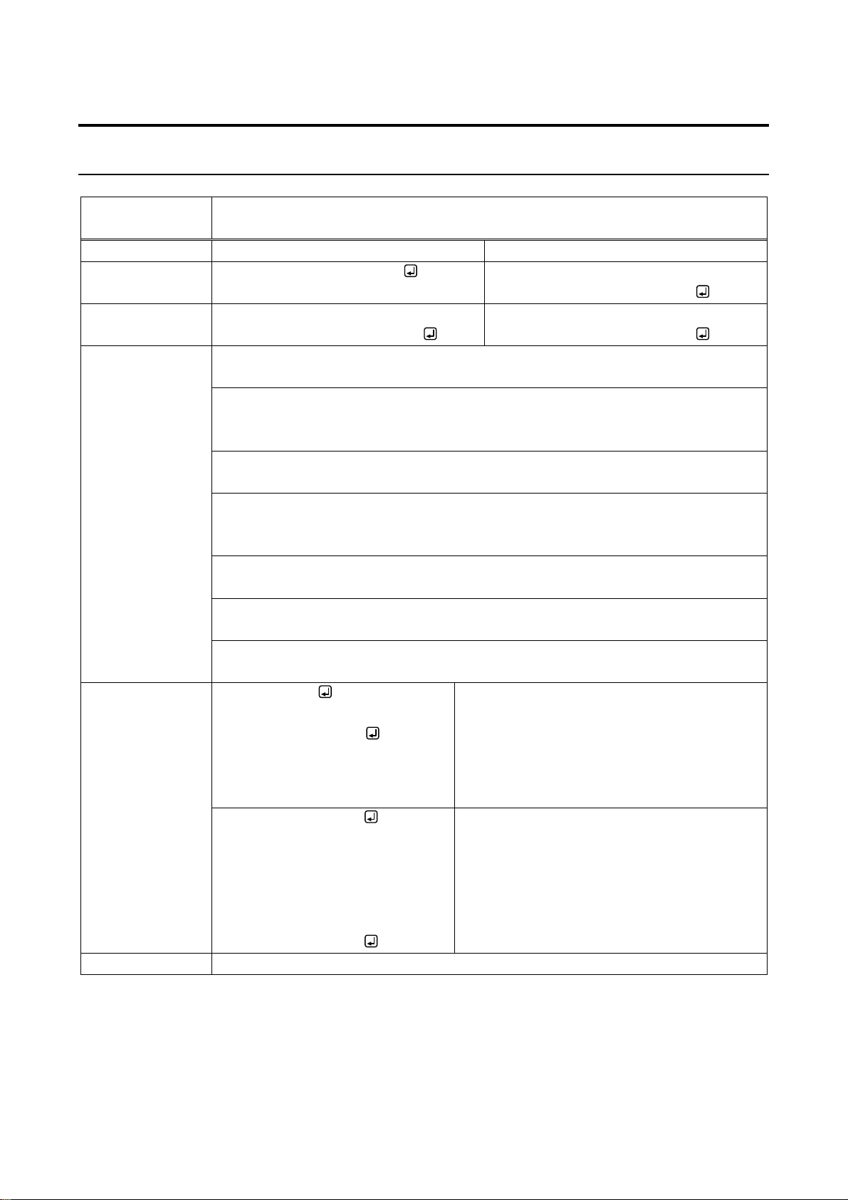
4.4.5 Setting communication interface values
@GRSS /
@SRSS
RS-232C communication setting
Function
Getting
Setting
Format
@GRSS, type, ch, reserved
@SRSS, type, ch, reserved,
baudrate,databit, stopbit, parity
Return value
@GRSS, type, ch, reserved,
baudrate,databit, stopbit, parity
@SRSS, type, ch, reserved,
baudrate,databit, stopbit, parity
Parameter
type: Type
1 = Input, 2 = Output
ch: Channel
ch_1 to ch_512: Channel
0 = All channels (only for setting), 1 to 512 = Channel1 to Channel512
reserved: Reservation
“1”fixed.
baudrate: Baud rate
0 = 4800 bps, 1 = 9600 bps [Default], 2 = 19200 bps, 3 = 38400 bps,
4 = 57600 bps, 5 = 115200 bps
databit: Data bit length
7 = 7 bit, 8 = 8 bit [Default]
stopbit: Stop bit
1 = 1 bit [Default], 2 = 2 bit
parity: Parity check
0 = NONE [Default], 1 = ODD, 2 = EVEN
Example
@GRSS,1,1,1
@GRSS,1,1,1,4,8,1,0
Getting RS-232C communication setting of
Input Channel1.
・Baud rate: 57600 bps
・Data bit length: 8 bit
・Stop bit: 1 bit
・Parity check: NONE
@SRSS,1,1,1,4,8,1,0
@SRSS,1,1,1,4,8,1,0
Setting RS-232C communication setting of
Input Channel1 as follows:
・Baud rate: 57600 bps
・Data bit length: 8 bit
・Stop bit: 1 bit
・Parity check: NONE
Completed normally.
Remarks
-
4.4.5.1 Setting RS-232C
NJR-CTB Command Guide
29
Page 30
NJR-CTB Command Guide
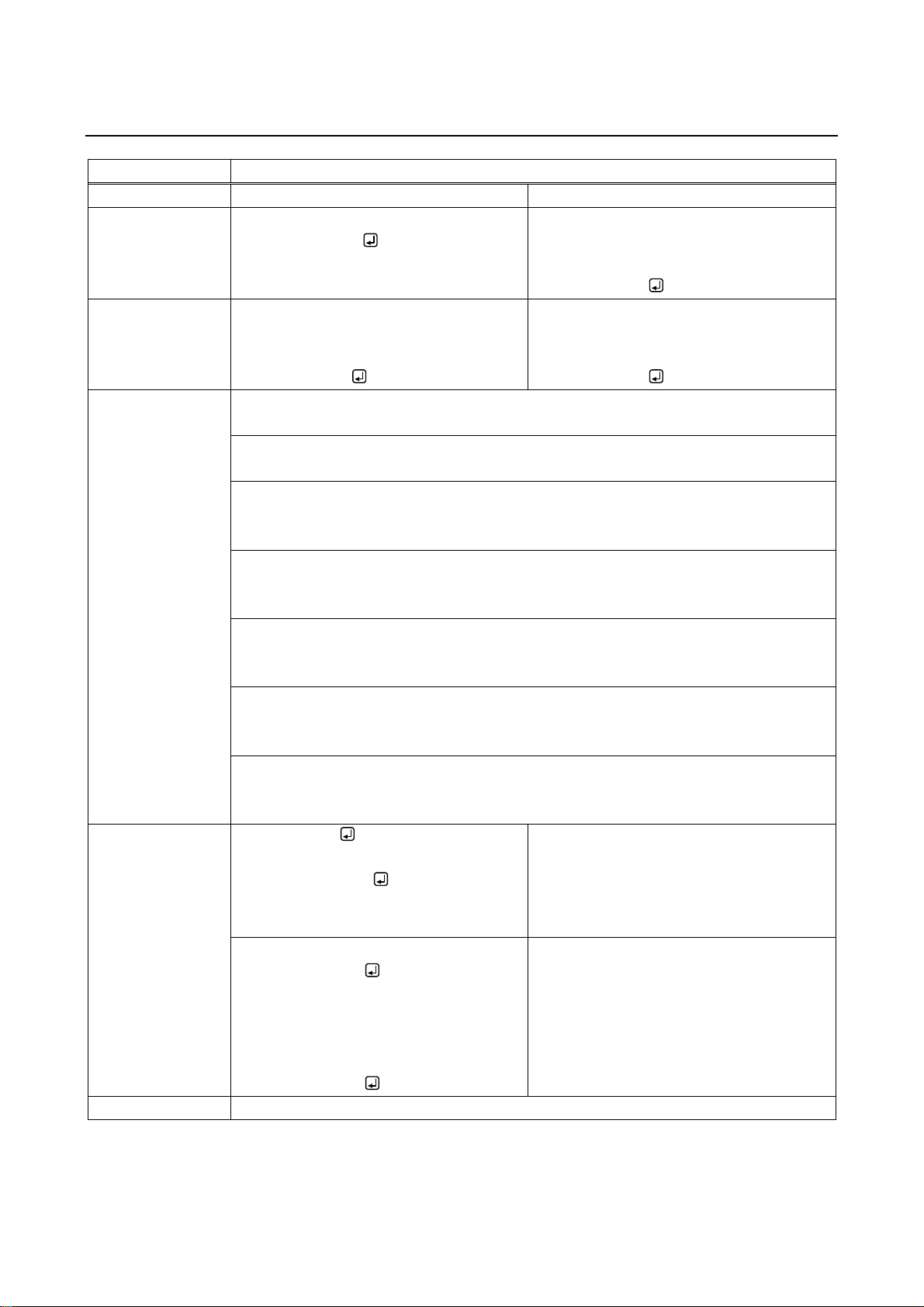
@GIPS / @SIPS
Setting LAN
Function
Getting
Setting
Format
@GIPS, type_1, ch_1, port_1 (,type_2,
ch_2, port_2・・・)
@SIPS, type_1, ch_1, port_1, mode_1,
ip_1, mask_1, gateway_1 (,type_2, ch_2,
port_2, mode_2, ip_2, mask_2,
gateway_2・・・)
Return value
@GIPS, type_1, ch_1, port_1, mode_1,
ip_1, mask_1, gateway_1 (,type_2,
ch_2, port_2, mode_2, ip_2, mask_2,
gateway_2・・・)
@SIPS, type_1, ch_1, port_1, mode_1,
ip_1, mask_1, gateway_1 (,type_2, ch_2,
port_2, mode_2, ip_2, mask_2,
gateway_2・・・)
Parameter
type_1 to type_512: Type
0 = CTB, 1 = Input, 2 = Output
ch_1 to ch_512:channel
1 to 512 = Channel1 to Channel512
port_1 to port_512: Connector
1 to 2 = Connector1 to 2
For other than CTB, ”1” fixed
mode_1 to mode_512: Mode
0 = Automatic (DHCP) [Default], 1 = Fixed
“0” is selected, the following three parameters will be invalid.
ip_1 to ip_512:IP address
0 to 255 = 8 bit (in decimal) × 4 combinations
[Default] Getting automatically
mask_1 to mask_512: Subnet mask
0 to 255 = 8 bit (in decimal) × 4 combinations
[Default] Getting automatically
gateway_1 to gateway_512: Default gateway
0 to 255 = 8 bit (in decimal) × 4 combinations
[Default] Getting automatically
Example
@GIPS,1,1,1
@GIPS,1,1,1,1,192.168.3.2,255.255.25
5.0,192.168.3.254
Getting LAN setting of Input channel1.
・Mode: Fixed
・IP address:192.168.3.2
・Subnet mask: 255.255.255.0
・Default gateway: 192.168.3.254
@SIPS,1,1,1,1,192.168.3.2,255.255.255
.0,192.168.3.254
@SIPS,1,1,1,1,192.168.3.2,255.255.255
.0,192.168.3.254
Setting LAN of Input channel1 as follows:
・Mode: Fixed
・IP address: 192.168.3.2
・Subnet mask: 255.255.255.0
・Default gateway: 192.168.3.254
Completed normally.
Remarks
-
4.4.5.2 CTB LAN settings
30
Page 31
NJR-CTB Command Guide
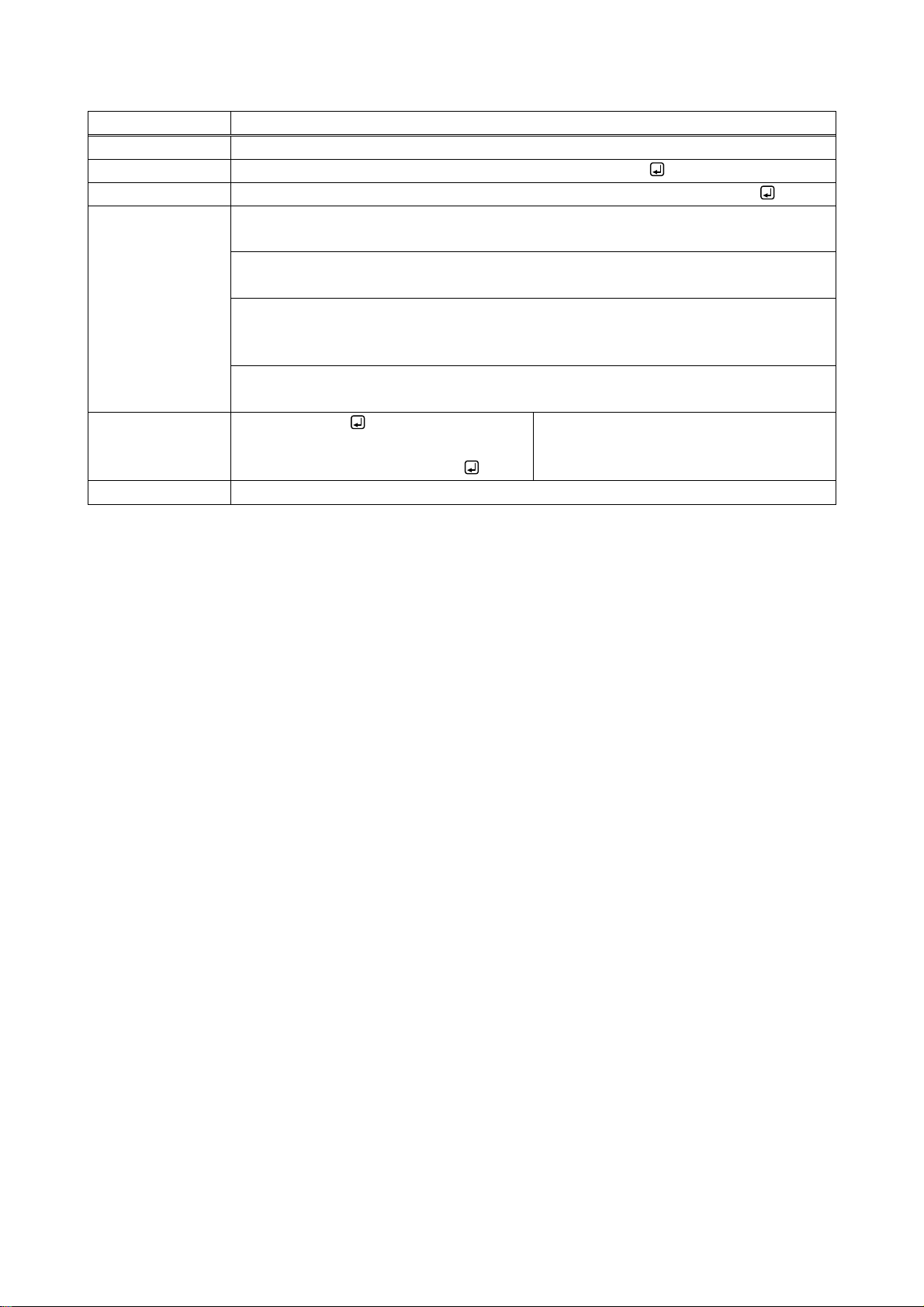
@GMCC
MAC address
Function
Getting
Format
@GMCC, type_1, ch_1, port_1 (, type_2, ch_2, port_2・・・)
Return value
@GMCC, type_1, ch_1, port_1, mac_1 (, type_2, ch_2, port_2, mac_2・・・)
Parameter
type_1 to type_512: Type
0 = CTB, 1 = Input, 2 = Output
ch_1 to ch_512: Channel
1 to 512 = Channel1 to Channel512
port_1 to port_512: Connector
1 to 2 = Connector1 to 512
For other than CTB, ”1” fixed
mac_1 to mac_512: MAC address
00 to FF = 8 bit (in hex) × 6 combination
Example
@GMCC,1,1,1
@GMCC,1,1,1, 0008E5690000
Getting the MAC address of Input
channel1.
00:08:E5:69:00:00
Remarks
-
31
Page 32
NJR-CTB Command Guide
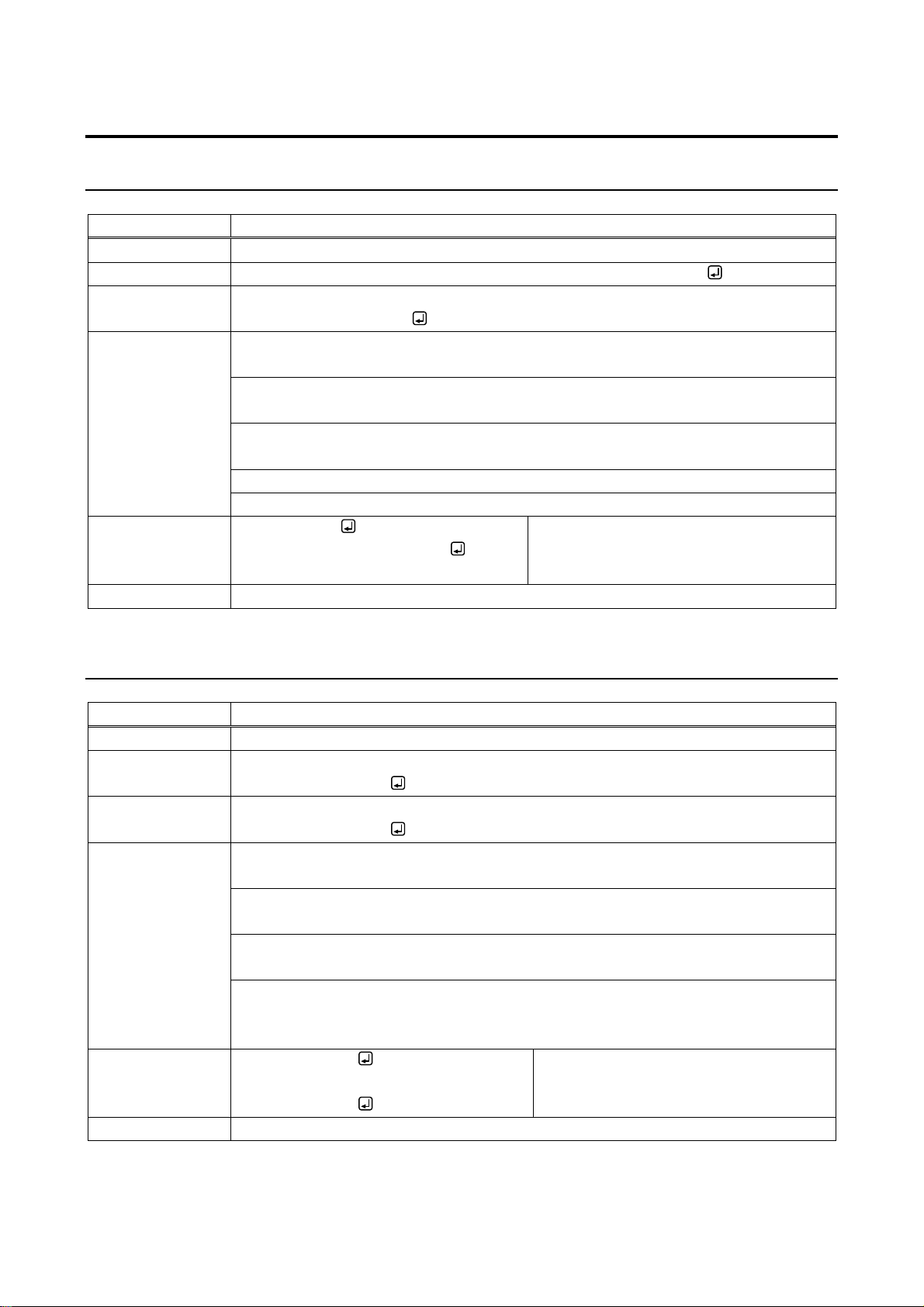
@GIVC
Version
Function
Getting
Format
@GIVC, type_1, ch_1, reserved_1 (, type_2, ch_2, reserved_2・・・)
Return value
@GIVC, type_1, ch_1, reserved_1, model_1, version_1 (, type_2, ch_2, reserved_2,
model_2, version_2・・・)
Parameter
type_1 to type_512: Type
0 = CTB, 1 = Input, 2 = Output
ch_1 to ch_512: Channel
1 to 512 = Channel1 to Channel512
reserved_1 to reserved_512: Reservation
“1” fixed
model_1 to model_512: Product model
version_1 to version_512: Firmware version
Example
@GIVC,0,0,1
@GIVC,0,0,1,NJR-CTB,1.0.0
Getting the information of the CTB.
・Product model: NJR-CTB
・Firmware version: 1.0.0
Remarks
-
@CLRC
Initializing setting
Function
Setting
Format
@CLRC, type _1, ch_1, reserved_1, comm_setting_1, (,type _2, ch_2, reserved_2,
comm_setting_2・・・)
Return value
@CLRC, type _1, ch_1, reserved_1, comm_setting_1 (,type _2, ch_2, reserved_2,
comm_setting_2・・・)
Parameter
type_1 to type_512: Type
0 = CTB, 1 = Input, 2 = Output
ch_1 to ch_512: Channel
0 = All channels, 1 to 512 = Channel1 to Channel512
reserved_1 to reserved_512: Reservation
“1” fixed
comm _setting_1 to comm_setting_512: Communication setting (initializing LAN and
RS-232C)
0 = Disabled [Default], 1 = Enabled
Example
@CLRC,1,2,1,0
@CLRC,1,2,1,0
Initializing settings of input channel2,
except for communication setting.
Completed normally.
Remarks
-
4.4.6 Maintenance
4.4.6.1 CTB version querry
4.4.6.2 Initialization and Reboot
32
Page 33
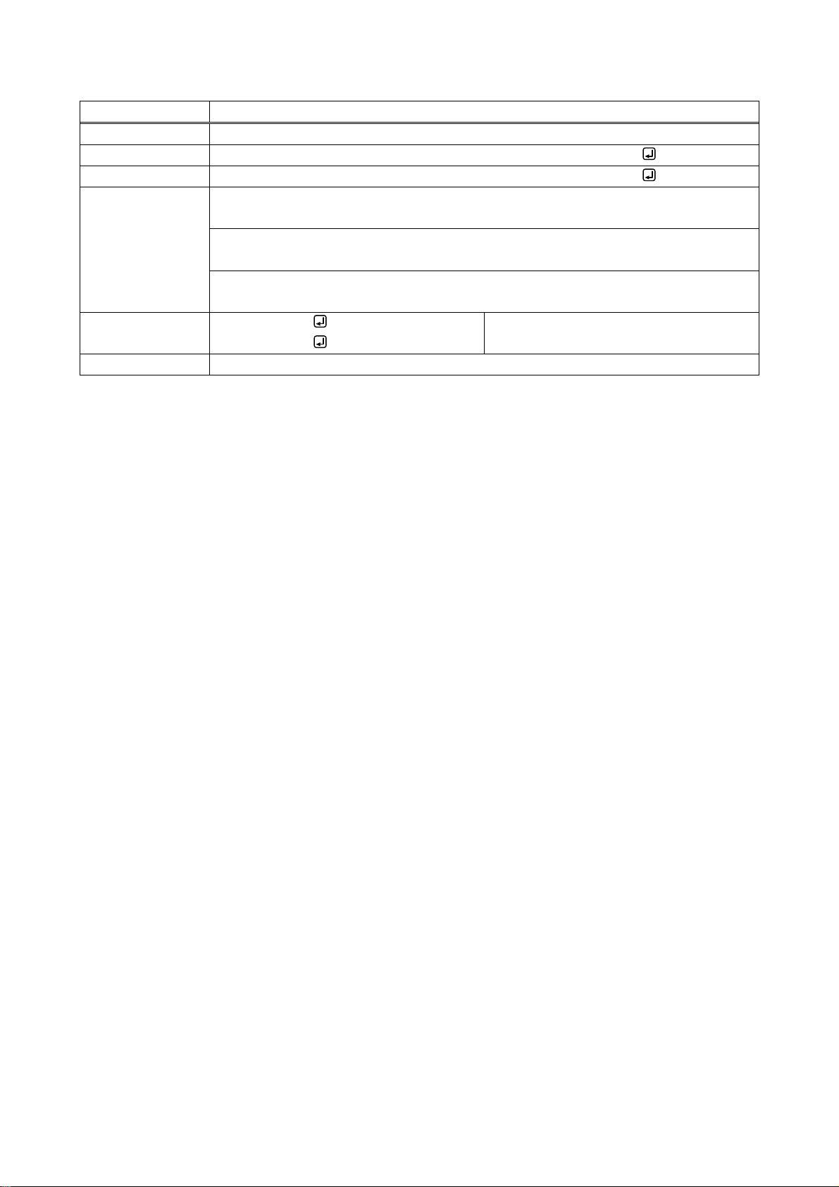
@RBTC
Reboot
Function
Setting
Format
@RBTC, type_1, ch_1, reserved_1 (,type_2, ch_2, reserved_2・・・)
Return value
@RBTC, type_1, ch_1, reserved_1 (,type_2, ch_2, reserved_2・・・)
Parameter
type_1 to type_512: Type
0 = CTB, 1 = Input, 2 = Output
ch_1 to ch_512: Channel
0 = All outputs, 1 to 512 = Channel1 to Channel512
reserved_1 to reserved_512: Reservation
“1” fixed
Example
@RBTC,1,2,1
@RBTC,1,2,1
Rebooting input channel2.
Completed normally.
Remarks
-
NJR-CTB Command Guide
33
Page 34

NJR-CTB Command Guide
Headquarters
IDK Corporation
7-9-1 Chuo, Yamato-shi, Kanagawa-pref.
242-0021 JAPAN
TEL: +81-46-200-0764 FAX: +81-46-200-0765
Email: [email protected] URL: http://www.idkav.com
USA
IDK America Inc.
72 Grays Bridge Road Suite 1-C, Brookfield, CT 06804
TEL: +1-203-204-2445
Email: [email protected] URL: http://www.idkav.com
Europe
IDK Europe GmbH
Lise-Meitner-Str. 6, D-40878 Ratingen
Email: [email protected] URL: http://www.idkav.com
Product information
Support
Arvanics Corporation
7-9-1 Chuo, Yamato-shi, Kanagawa-pref.
242-0021 JAPAN
TEL: +81-46-259-6920 FAX: +81-46-259-6930
Email: [email protected] URL: http://www.arvanics.com
NJR-CTB User’s guide (Command Guide)
Ver.1.1.1
Revised on: 30 January 2018
Information in this document is subject to change without notice.
All rights reserved. All trademarks mentioned are the property of their respective owners.
34
 Loading...