

Page 1

Dante Audio Bridge Interf a c e
NJR-AB08DAN
<User Guide>
<Command Guide>
Ver.1.0.0
Thank you for choosing our product.
To ensure the best performance of this product, please read this user guide fully and carefully before
using it and keep this manual together with the product for future reference as needed.
IDK Corporation
Page 2

NJR-AB08DAN User Guide/Command Guide
Trademarks
Audinate®, the Audinate logo and Dante are trademarks of Audinate Pty Ltd.
The terms HDMI and HDMI High-Definition Multimedia Interface, and the HDMI Logo are trademarks or
registered trademarks of HDMI Licensing Administrator, Inc. in the United States and other countries.
IP NINJAR is a registered trademark of IDK Corporation in Japan.
All other company and product names mentioned in this manual are either registered trademarks or
trademarks of their respective owners. In this manual, the “®” or “™” marks may not be specified.
2
Page 3

NJR-AB08DAN User Guide/Command Guide
The lasers in this product meet Class 1 Laser Safety per FDA/CDRH and
クラス 1
レーザ製品
CLASS 1
LASER PRODUCT
Before reading this manual
All rights reserved.
Some information contained in this User guide such as exact product appearance, diagrams, menu
operations, communication commands, and so on may differ depending on the product version.
This User guide is subject to change without notice. You can download the latest version from IDK’s
website at: http://www.idkav.com
EN (IEC) 60825 laser safety standards which specifies design safety.
FCC STATEMENT
This equipment has been tested and found to comply with the limits for a Class A digital device, pursuant to
part 15 of the FCC Rules. These limits are designed to provide reasonable protection against harmful
interference when the equipment is operated in a commercial environment. This equipment generates, uses,
and can radiate radio frequency energy and, if not installed and used in accordance with the instruction
manual, may cause harmful interference to radio communications. Operation of this equipment in a residential
area is likely to cause harmful interference, in which case the user will be required to correct the interference
at his own expense.
CE MARKING
This equipment complies with the essential requirements of the relevant European health, safety and
environmental protection legislation.
WEEE MARKING
Waste Electrical and Electronic Equipment (WEEE), Directive 2002/96/EC
(This directive is only valid in the EU.)
This equipment complies with the WEEE Directive (2002/96/EC) marking requirement.
The left marking indicates that you must not discard this electrical/electronic equipment in
domestic household waste.
3
Page 4
NJR-AB08DAN User Guide/Command Guide
Enforcement Symbol
Description
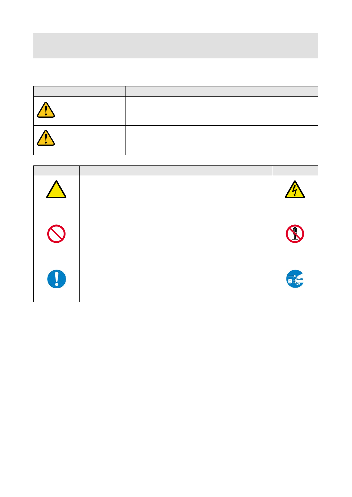
Indicates the presence of a hazard that may result in death or serious
Indicates the presence of a hazard that may cause minor personal
Symbol
Description
Example
Hazard
disassemble
Warning
Caution
Safety Instructions
Read and understand all safety and operating instructions before using this product. Follow all instructions
and cautions as detailed in this document.
personal injury if the warning is ignored or the product is handled
incorrectly.
This symbol is intended to alert the user. (Warning and caution)
injury or property damage if the caution is ignored or the product is
handled incorrectly.
Caution
This symbol is intended to prohibit the user from specified actions.
Prohibited
This symbol is intended to instruct the user.
Instruction
Electrical
Do not
Unplug
4
Page 5

NJR-AB08DAN User Guide/Command Guide
Instruction
● Do not place the product upon a surface that may give way or that m ay become
Otherwise, it may move unexpectedly or it may fall and lead to injury.
● Installation work must be performed by p rofessionals.
differences may cause fire or other difficulties.
● Keep out any foreign objects.
・
・
・
contact your IDK representative.
disassemble
● Do not repair, modify or disassemble.
● Do not touch the product and connected cables during electrical storms.
Instruction
● Clean the power plug regularly.
Warning
■ For lifting heavy products:
● Lifting must be done by two or more personne l.
To avoid injury: When lifting the product, bend your knees, keep your back straight and get close to it with two or
more persons.
■ For installing and connecting products :
unstable.
Install the product in a secure and stable place to prevent it from falling and possibly causing injury.
Prohibited
Instruction
● Secure the product if installing in locations prone to vibration or movement.
The product is intended to be installed by skilled technicians. For installation, please contact a system integrator
or IDK. Improper installation may lead to the risk of fire, electric shock, injury, or property damage.
● Insert the power plug into an outlet that is unobstructed.
Unobstructed access to the plug enables unplugging the product in case of any extraordinary failure, abnormal
situation or for easy disconnection during extended periods of non-use.
● Insert the power plug into an appropriate outlet completely.
If the plug is partially inserted, arching may cause the connection to overheat, increasing the risk of electrical
shock or fire. Do not use a damaged plug or connect to a damaged outlet.
● Unplug the product from the AC power source during installation or service.
When connecting peripheral devices to this product, unpl ug all involved devices from outlets. Ground potential
■ For operating products:
To avoid fire or electric shock, do not permit foreign objects, such as metal and paper, to enter the product from
vent holes or other apertures.
● For power cable/ plug:
Prohibited
Do not
Do not touch
Do not scratch, heat, or modify, including splicing or lengthening them.
Do not pull, place heavy objects on them, or pinch them.
Do not bend, twist, tie or clamp them together forcefully.
Misuse of the power cable and plug may cause fire or electric shock. If power cables/pl ugs become damaged,
Since the product includes circuitry t hat us es potenti ally lethal, high voltage l evels, dis ass embly by unauthorized
personnel may lead to the risk of fire or electric shock. For internal inspection or repair, contact your IDK
representative.
Contact may cause electric shock
If the plug is covered in dust, it may increase the risk of firer.
5
Page 6

NJR-AB08DAN User Guide/Command Guide
● Unplug immediately if the product smokes, makes unusual noise, or produces a
maintenance and repair, contact your IDK representative.
Warning
■ If the following problem occurs:
burning odor.
If you continue to use the product under these conditions, it may cause electric shock or fire.
● Unplug immediately if the product is damaged by falling or having been dropped.
Unplug
If you continue to use the product under these conditions, it may increase the r isk of electrical shock or fire. For
maintenance and repair, cont act your IDK representative.
● Unplug immediately if water or other objects are directed inside.
If you continue to use the product under these conditions, it may increase the risk of electrical shock or fire. For
6
Page 7

● Do not place the product in a location where it will be subjected to high
Exceeding the rating of an outlet may increase the risk of fire and electric shock.
No wet hands
● Do not handle power plug with wet hands.
● Use and store the product within the specified tempe rature/humidity range.
Reinstall the originally supplied rubber feet using only the originally supplied screws.
Prohibited
● Use only the supplied power cable and AC adapter.
● If the product won’t be used for an extended period of time, unplug it.
To prevent electric shock.
Caution
■ For installing and connecting products :
NJR-AB08DAN User Guide/Command Guide
temperatures.
If the product is subjected to direct sunlight or high temperatures while under operation, it may affect the
product’s performance and reliability and may increase the risk of fire.
● Do not store or operate the product in dusty, oil smoke filled, or humid place.
Prohibited
If the product is placed near humidifiers or in a dusty area, it may increase the risk of fire or electric shock.
● Do not block the vent holes.
If ventilation slots are blocked, it may cause the product to overheat, affecting performance and reliability and
may increase the risk of fire.
● Do not place or stack heavy items on the product.
Failure to observe this precaution may result in damage to the product and other property and may lead to the
risk of personal injury.
● Do not exceed ratings of outlet and wiring devices.
Failure to observe this precaution may i ncrease the risk of electrical shock.
If the product is used outside the specified range for temperature and humidity continuously, it may increase the
risk of fire or electric shock.
● Do not place the product at elevations of 1.24 mi. (2,000 m) or higher above sea
level.
Failure to do so may shorten the life of the internal parts and result in malfunctions.
Instruction
● When mounting the product into the rack, provide suffi cient cooling space.
Mount the product in a rack meeting EIA standards, and maintain spaces above and below for air circulation. For
your safety as required, attach an L-shaped bracket in addition to the panel mount bracket kit to improve
mechanical stability.
● Never insert screws without the rubber feet into the threaded holes on the bottom
of the product.
Never insert screws without the rubber feet into the threaded holes on the bottom of the product. Doing so may
lead to damage when the screws contact electrical circuitry or components inside the product.
■ For operating products:
● Do not use the supplied power cable and AC adapter with other products.
If non-compliant adapter or power cables are used, it may increase the risk of fire or elect rical shock.
Failure to observe this precaution may increase the risk of fire.
● Unplug the product before cleaning.
Unplug
7
Page 8

NJR-AB08DAN User Guide/Command Guide
Table of Contents
1 About this Guide ........................................................................................................................................ 9
2 Included items .......................................................................................................................................... 10
3 Precautions for shipping .......................................................................................................................... 11
4 Product outline ......................................................................................................................................... 12
5 Features ................................................................................................................................................... 13
6 Panels ...................................................................................................................................................... 14
7 System Configuration Example................................................................................................................ 15
8 Precautions .............................................................................................................................................. 16
8.1 Attaching Rubber feet ......................................................................................................................... 16
8.2 Installation ........................................................................................................................................... 16
8.3 Cabling ................................................................................................................................................ 17
8.3.1 Fiber optic cable for extension .................................................................................................... 17
8.3.2 SFP+ optical transceiver ............................................................................................................. 18
8.3.3 DIN plug AC adapter with locking mec hanism ............................................................................ 19
9 Basic Operation ....................................................................................................................................... 21
9.1 Controlled by NJR-CTB ...................................................................................................................... 22
9.2 Dante................................................................................................................................................... 23
9.2.1 Dante network connection ........................................................................................................... 23
9.2.2 Dante Controller .......................................................................................................................... 24
9.3 Initialization ......................................................................................................................................... 25
9.4 Reboot ................................................................................................................................................ 25
10 Setting ...................................................................................................................................................... 26
10.1 Setting audio ....................................................................................................................................... 27
10.1.1 Audio crosspoint mode ................................................................................................................ 27
10.1.2 Assigning audio channel ............................................................................................................. 29
10.2 Setting LAN ......................................................................................................................................... 30
10.2.1 LAN ............................................................................................................................................. 30
10.2.2 MAC address............................................................................................................................... 30
11 Command ................................................................................................................................................. 31
11.1 Summary ............................................................................................................................................. 31
11.2 Command list ...................................................................................................................................... 32
11.3 Details of commands .......................................................................................................................... 33
11.3.1 Error status .................................................................................................................................. 33
11.3.2 Setting audio ............................................................................................................................... 34
11.3.3 Setting LAN ................................................................................................................................. 36
11.3.4 Advanced setting ......................................................................................................................... 38
12 Product specification ................................................................................................................................ 39
13 Troubleshooting ....................................................................................................................................... 40
8
Page 9

NJR-AB08DAN User Guide/Command Guide
Fiber optic cables
Source device
HDMI
NJR-T01UHD
NJR-R01UHD
HDMI
4K monitor
Chapter 2 to 13
4K@60 4K@60
PC for control
(For NJR-CTB)
LAN
LAN
IP-NINJAR
Management &
Control Platform
(NJR-CTB)
IP-NINJAR net wo rk
10 GbE swit c h
NJR-AB08DAN
Dante network
1 GbE swit c h
Mixer
(Dante supported)
Speakers
(Dante supported)
Chapter 9
Model
User Guide
Command Guide
NJR-T01UHD/NJR-R01UHD
NJR-T01UHD/NJR-R01UHD
NJR-T01UHD/NJR-R01UHD
User Guide
Command Guide
NJR-T01SDI
NJR-T01SDI
NJR-T01SDI
User Guide
IP-NINJAR Configurator
IP-NINJAR Configurator User Guide
1 Abou t this Gui d e
This user guide explains how to use the Dante Audio Bridge Interfac e, NJR-AB08DAN.
For other products of IP-NINJAR series, see “[Table 1.1] Document for IP-NINJAR products”.
[Fig. 1.1] Document structure
[Table 1.1] Document for IP-NINJAR products
User Guide
NJR-TW01UHD/NJR-RW01UHD NJR-TW01UHD/NJR-RW01UHD
User Guide
NJR-T04HD/NJR-R04HD NJR-T04HD/NJR-R04HD
User Guide
Command Guide
NJR-TW01UHD/NJR-RW01UHD
Command Guide
NJR-T04HD/NJR-R04HD
Command Guide
NJR-AB08DAN NJR-AB08DAN User Guide/Command Guide
NJR-CTB NJR- CTB
NJR-CTB
9
Page 10
NJR-AB08DAN User Guide/Command Guide
2 Included items
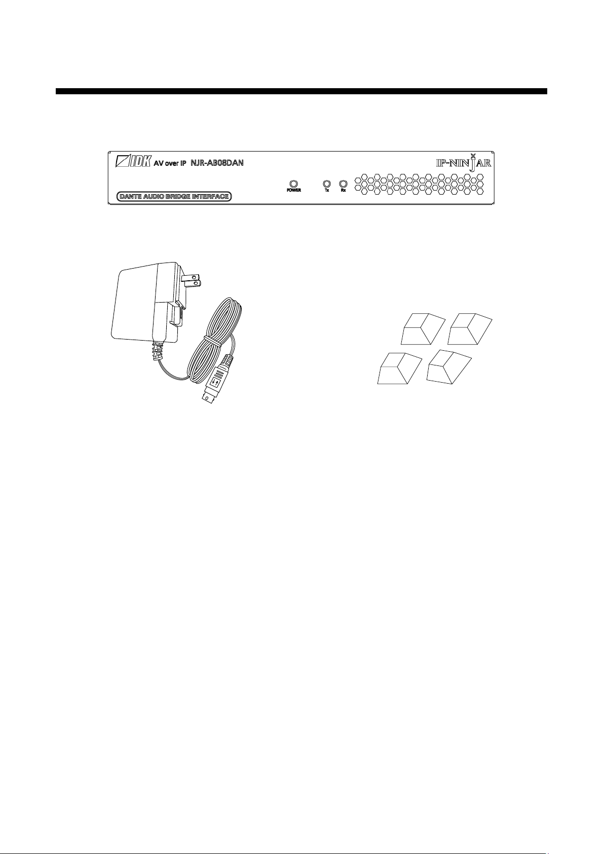
Ensure that all items illustrated below are included in the package.
If any items are missing or damaged, please contact IDK.
One (1) NJR-AB08DAN
One (1) DIN plug AC adapter with
locking mechanism (3.9 ft. (1.2 m))
[Fig. 2.1] Included items
Four (4) Rubber feet
10
Page 11

NJR-AB08DAN User Guide/Command Guide
SFP+Optical
transceiver
UnpluggingPlugging
Bail c las p
Open the bail clasp in
downward direction. Grasp
the transceiver and careful ly
unplug it from the port
Close the bail clasp and
slide it into the port
3 Pr ecautions for shipping
The NJR-AB08DAN has an SFP+ optical transceiver that makes it vulnerable to damage caused by
mishandling during shipment if it is improperly packaged.
If, for any reason, you need to ship the NJR-AB08DAN, use the carton and cushion which were used at the
time of purchase. Make sure to plug the attached dust cap into the SFP+ optical transceiver. If you do not
have the carton and cushion, unplug the SFP+ optical transceiver from the NJR and plug the dust cap, and
then put it in an antistatic bag with enough cushion. Use the appropriate carton and cushion for shipping.
[Fig. 3.1] Removing and installing SFP+ optica l transceiver
11
Page 12

NJR-AB08DAN User Guide/Command Guide
IP-NINJAR net wo rk
Fiber optic cables
10 GbE swit c h
Source device
HDMI
NJR-T01UHD
NJR-AB08DAN
NJR-R01UHD
HDMI
4K monitor
4K@60
4K@60
Dante network
1 GbE swit c h
Mixer
(Dante supported)
Speakers
(Dante supported)
Multimode fiber
NJR-AB08DAN-MM
Singlemode fiber
NJR-AB08DAN-SM
4 Product outline
The NJR-AB08DAN transcodes audio signal directly between the IP-NINJAR and Dante protocol
environments. Audio signal transport is enabled from NJR encoders to Dante devices and from Dante device
to NJR decoders.
The NJR-AB08DAN can receive up to four audio streams from IP-NINJAR encoders and output up to eight
channels in Dante protocol. The bridge can also accept up to 8-channel audio from Dante sources, outputting
IP-NINJAR protocol in up to four audio streams.
Audio can be set from the NJR-CTB (IP-NINJAR Management & Control Platform).
[Fig. 4.1] HDMI signals transmission
Note:
Please use the NJR-AB08DAN with a combination of IP-NINJAR products.
The NJR-AB08DAN cannot be connected to OPF or FDX series products.
■ Multimode fiber and singlemode fiber models
Cable type Model Number
12
Page 13

NJR-AB08DAN User Guide/Command Guide
■
NJR-AB08DAN
Multimode fiber
(OM3) : Up to 984 ft.
(300 m)
Singlemode fiber (OS1)
: Up to 6.21 mi. (10 km)
Singlemode fiber (OS1)
: Up to 24.85mi. (40 km, optional)
Protocol conversion
IP-NINJAR → Dante: up to 8 chs
IP-NINJAR ← Dante: up to 8 chs
IP-NINJAR audio
Fiber optic
Input/Output
1
Dante audio
LAN
Primary/Secondary
Up to 328 ft. (100 m)
5 Features
Audio
・ Transcoding audio signal between IP- NINJAR and Dante protocols
・ Receiving up to four (4) audio streams from IP-NINJAR encoders and outputting as Dante protocol up
to eight (8) channels
・ Receiving up to 8-channel Dante audio from Dante devices and outputting as IP-NINJAR protocol up
to four (4) audio streams
・ Dante audio can be embedded to HDMI signal at IP-NINJAR decoder
・ Dante audio can be de-embedded to analog audio signal at IP-NINJAR decoder
■ Network
・ Controllable through network using the NJR-CTB
[Fig. 5.1] NJR-AB08DAN
13
Page 14
NJR-AB08DAN User Guide/Command Guide
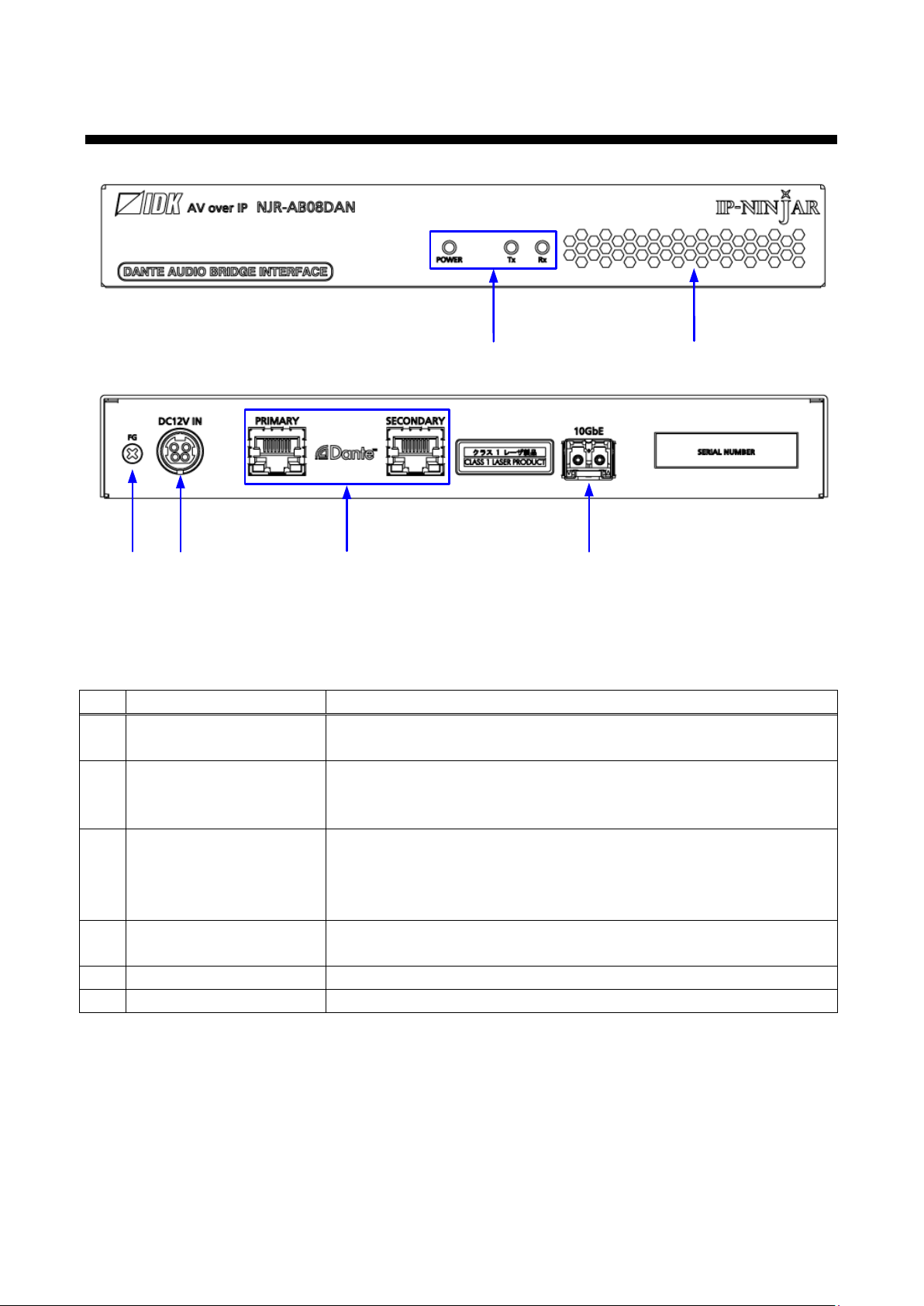
③
⑥
⑤
②
①
④
#
Feature
Description
(PRIMARY/SECONDARY)
Connects to the network switch that is connected to Dante devices
IP-NINJAR connector
IP-NINJAR protocol connector
a fiber optic cable
Status LEDs
POWER : Illuminates when power is supplied from the AC adapter
Vent holes
Prevents internal temperature raise
6 Panels
[Fig. 6.1] NJR-AB08DAN drawing
[Table 6.1] NJR-AB08DAN features
① Dante connectors
②
③
④
⑤ Power supply connector For the provided AC adapter
⑥ FG (Frame ground) Use for bonding chassis to local ground. An M3 screw is used
Dante protocol connector
Connects to a 10 GbE switch that is connected to IP-NINJAR devices via
TX : Blinks when a valid code is being sent to 10 GbE switch
RX : Blinks when a valid code is being received from
10 GbE switch
Do not block ventilation holes
14
Page 15

NJR-AB08DAN User Guide/Command Guide
Multimode fiber (OM3) : Up to 984 ft. (300 m)
Singlemode fiber (OS1) : Up to 6.21 mi. (10 km)
Singlemode fiber (OS1) : Up to 24.85mi. (40 km, optional)
4K monitor
HDMI/DVI
Up to 16 ft. (5 m)
PC for control
*3
NJR-T01UHD
HDMI/DVI
Up to 16 ft. (5 m)
Source device
NJR-R01UHD
LAN
*1
Speakers
Power amp.
Analog audio
10 GbE swit c h
4K@60
4K@60
①
① ②
②
②
LAN
*2
LAN
*2
NJR-AB08DAN
Dante network
1 GbE swit c h
Mixer
(Dante supported)
Speakers
(Dante supported)
①②
① ②
① ②
IP-NINJAR net wo rk
*1
Connect the NJR-CTB to NJR-T01UHD/NJR-R01UHD or 10GbE switch
*2
Connect the P C for control to NJR-CTB or NJR-T01UHD/NJR-R01UHD
*3
IP-NINJAR products are controlled from the PC for cont rol
IP-NINJAR Management &
Control Platform
(NJR-CTB)
7 S ystem Co nfi gu r ation Example
Configuration example: Connecting the NJR-AB08DAN to IP-NINJAR and Dante networks
① Audio signal that is input from source device to the NJR-T01UHD is transmitted to the NJR-AB08DAN.
The NJR-AB08DAN transcodes the audio signal to Dante protocol and outputs the signal to Dante
network.
② Audio signal that is input from Dante network to the NJR-AB08DAN is transcoded to IP-NINJAR protocol.
The audio signal is transmitted from IP-NINJAR network to the NJR-R01UHD, and the signal can be
output from the NJR-R01UHD HDMI output connector or analog audio output connector.
[Fig. 7.1] NJR-AB08DAN is connected to IP-NINJAR and Dante networks
15
Page 16

NJR-AB08DAN User Guide/Command Guide
Bad example
Good examp le
Good examp le
8 Precautions
Before connecting to external devices, follow the precautions below.
8.1 Attaching Rubber feet
First, clean the bottom surface of the NJR-AB08DAN as needed, and then peal the release papers from the
rubber feet and place them in each of the four corners.
8.2 Installation
When installing the NJR-AB08DAN, please observe the following precautions.
・ Do not stack or place one NJR-AB08DAN directly on top of another NJR-AB08DAN
・ Do not block vent holes. To provide adequate ventilation, maintain sufficient clearances around the
NJR-AB08DAN (1.2 in. (30 mm) or more)
・ When the NJR-AB08DAN needs to be mounted in an enclosed space or an EIA rack without using IDK’s
rack mounting hardware (RM-SF and RM-SH), ensure that a sufficient ventilation/cooling system is
provided to keep the ambient temperature at 104°F (40°C) or lower. If inadequately vented, the product’s
service life, operation, and reliability may be affected.
Maintain adequate clearances (1.2 in. (30 mm) or more) as shown below.
16
[Fig. 8.1] Necessary clearances
Page 17

NJR-AB08DAN User Guide/Command Guide
10 GbE s witch
Fiber optic cables
NJR-AB08DAN
Output connector
for extension
Input connector
for extension
Output connector
for extension
Input connector
for extension
8.3 Cabling
When connecting the NJR-AB08DAN to external devices, please observe the following precautions.
・ Read manuals for the external devices
・ Before connecting cables to the NJR-AB08DAN or an external device, dissipate static electricity by
touching grounded metal such as equipment racks before handling signal cables. Failure to observe this
precaution may result in ESD (electrostatic discharge) damage.
・ Power all units off before connecting cables
・ Be sure to fully seat all plugs and connections and dress cables to reduce stress on connectors
8.3.1 Fiber optic cable for extension
The NJR-AB08DAN can reach their full potential by selecting appropriate fiber optic cables for long-haul
extension and installing the cable correctly.
Connect the output connector of this device to the input connector of the 10 GbE switch.
Connect the input connector of this device to the output connector of the 10 GbE switch.
[Fig. 8.2] Connecting fiber optic cable
Note:
For the connectors of 10 GbE switch, refer to the switch’s manual.
17
Page 18

NJR-AB08DAN User Guide/Command Guide
Left
: without dust cap
Right : with dust cap
Before cleaning After cleaning
Item
10G-MM-SFP
10G-SM-SFP
10G-SM40-SFP (Optional)
Fiber
Multimode fiber
Singlemode fiber
Singlemode fiber
Wave length
850 nm (VCSEL laser (*))
1310 nm (DFB laser (*))
1550 nm (EML laser (*))
Max. extension distance
OM3: 984 ft. (300 m)
OS1: 6.21 mi. (10 km)
OS1: 24.85 mi. (40 km)
Receiver sensitivity (OMA)
@10.3Gbps
-11.1 dBm or higher
-12.6 dBm or higher
-16 dBm or higher
Average Launch Power
-5 dBm to -1 dBm
-8.2 dBm to +0.5 dBm
-1 dBm to +2 dBm
Max. input power
+0.5 dBm
+0.5 dBm
-1 dBm
Connector
LC (Duplex)
・ To polish connectors:
For SFP+ optical transceiver for multimode
: PC polishing is recommended.
For SFP+ optical transceiver for singlemode : UPC polish ing is recom mended.
Note: APC polishing is not supported.
・ Extension distance varies depending on attenuation of the fiber, connector and other contact portions
・ Make sure not to exceed the allowable tension and bend radius of fiber optic cable or the performance of
the product and the life of the fiber optic cable may be affected
・ Plug the dust caps to both faces of the fiber optic cable when connecting the fiber optic cable and when not
in use
・ Before inserting a fiber optic cable, make sure there is no damage or dirt on the end-face of the optical
connector. Clean up it or NJR-T01SDI may not operate correctly
[Fig. 8.3] Dust caps [Fig. 8.4] Cleaning connector
8.3.2 SFP+ optical transceiver
The fiber type and transmission distance vary depending on the SFP+ optical transceiver.
[Table 8.1] Specification of standard SFP+ optical transceiver
* The lasers in these models meet class1.
・ When no fiber optic cable is connected, plug dust caps
・ Do not use the SFP+ optical transceiver for other products. Also, do not connect fiber optic cables that is
connected to other products to the SFP+ optical transceiver or the SFP+ optical transceiver ma y be
damaged
・ If you need to replace the SFP+ optical transcei ver, ple as e contact us .
18
Page 19

NJR-AB08DAN User Guide/Command Guide
①
②
③
④
This tab should be fixed into
the part of the AC adapter
Tab
8.3.3 DIN plug AC adapter with locking mechanism
The shapes of AC plugs with screw locking mechanism vary from country to country. The AC plug can be
removed from the AC adapter.
Removing AC plug:
Slide the AC plug (②) from the AC adapter while holding down the portion mentioned below (①)
[Fig. 8.5] Removing AC plug (Example: Plug type A)
Attaching AC plug:
Gently slide the AC plug into the AC adapter (③) until it clicks (④)
[Fig. 8.6] Attaching AC plug (Example: Plug type A)
19
Page 20

NJR-AB08DAN User Guide/Command Guide
Plugging Unplugging
Hold this part and pull
the DC plug
■ Plugging and unplugging DC plug
Plug the DC plug to the power supply connector of the unit until it clicks
Hold the portion mentioned below when unplu gg ing th e DC plug
[Fig. 8.7] Plugging and unplugging DC plug
20
Page 21

NJR-AB08DAN User Guide/Command Guide
Fiber optic cables
Source device
HDMI
NJR-T01UHD
NJR-R01UHD
HDMI
4K monitor
4K@60 4K@60
PC for control
(For NJR-CTB)
LAN
LAN
IP-NINJAR
Management &
Control Platform
(NJR-CTB)
IP-NINJAR net wo rk
10 GbE swit c h
NJR-AB08DAN
Dante network
1 Gb switch
Mixer
(Dante supported)
Speakers
(Dante supported)
9 Basic Operatio n
IP-NINJAR network can be controlled from the NJR-CTB, and Dante network can be controlled from the
Dante Controller.
【See: 9.2.2 Dante Controller】
[Fig. 9.1] Setting NJR-AB08DAN
21
Page 22

NJR-AB08DAN User Guide/Command Guide
MAINTENANCE connector
Tablet
MAINTENANCE
NJR-CTB
PC for control
LAN cable
*2
Communication
command
TCP: 1100
Command
server
WEB server
Browser
HTTP: 80
LAN
LAN connector
HUB
LAN cable
*1
10 GbE switch
Fiber optic
cables
LAN connector
NJR-T01UHD or NJR-R01UHDNJR-CTB
NJR-T01UHD
NJR-T01UHD
NJR-R01UHD
NJR-AB08DAN
Fiber optic
cables
*1
LAN connector on NJR-CTB should be connected to the LAN connector on NJR-T01UHD/NJR-R01UHD or 10 GbE switch.
*2
PC for control should be connected to the MAINTENANCE connector on NJR-CTB or the LAN c onnector on NJR-T01UHD/NJR-R01UHD.
9.1 Controlled by NJR-CTB
The NJR-CTB is the control device to command comprehensively IP-NINJAR devices via a 10 GbE switch.
All IP-NINJAR devices that are connected to the network can be controlled using WEB browser or LAN
communication commands by connecting the NJR-CTB to a 10 GbE switch or IP-NINJAR
encoders/decoders.
For details of operations from WEB browser and communication commands, refer to the NJR-CTB User
Guides.
[Fig. 9.2] Controlled by NJR-CTB
22
Page 23

NJR-AB08DAN User Guide/Command Guide
Dante network
Speakers
Power amp.
(Dante supported)
Analog audio
Dante connector
(Primary)
Dante connector
(Secondary)
Speakers
Power amp.
(Dante supported)
Analog audio
Dante Controller
(Controlling devices with Dante)
Dante network
Network switch
(1 gigabit or larger)
Network switch
(1 gigabit or larger)
Laptop
IP-NINJAR net wo rk
Source device
HDMI
NJR-T01UHD
NJR-R01UHD
HDMI
4K monitor
4K@60 4K@60
10 GbE swit c h
Fiber optic cables
NJR-AB08DAN
9.2 Dante
Dante (Digital Audio Network Through Ethernet) is an audio networking technology developed by Audinate.
The NJR-AB08DAN converts digital and analog audio signals from IP-NINJAR encoders into Dante format
with 44.1 kHz, 48 kHz, 88.2 kHz, 96 kHz, 176.4 kHz, or 192 kHz sampling frequency and 24-bit sample size.
Audio that is input from Dante network can be output to a decoder in IP-NINJAR network.
9.2.1 Dante network connection
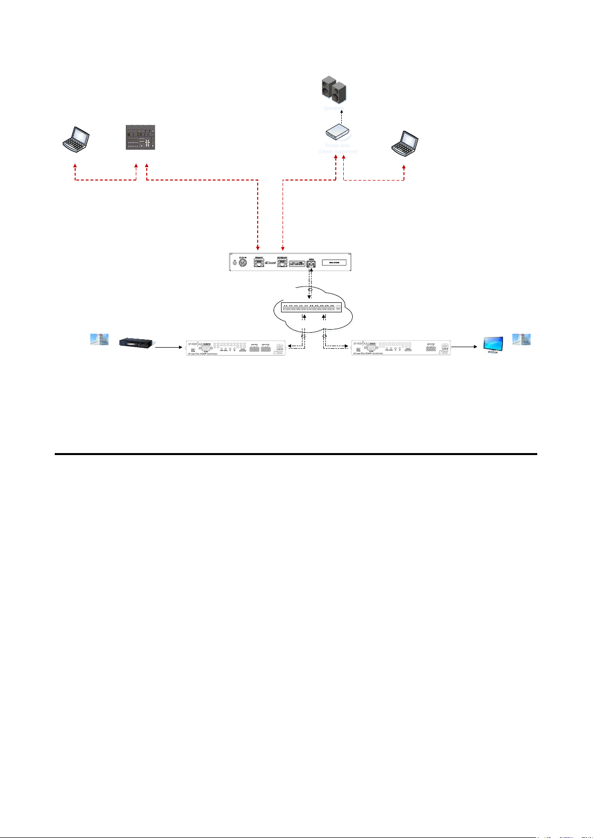
Redundant connection and Daisy chain connection (Redundant connection is set by default) are supported
for Dante devices.
The IP address for Dante connectors (Primary and Secondary) is automatically obtained over IP network.
Use a Cat5e or better cable.
[Fig. 9.3] Redundant connection
Note:
For redundant operation, do not connect the Dante primary and secondary connectors to the same
IP network.
23
Page 24
NJR-AB08DAN User Guide/Command Guide
Mixer (Dante supported)
Speakers
Power amp.
(Dante supported)
Analog audio
Primary
connector
Secondary
connector
Primary
connector
Secondary
connector
Dante connector
(Primary)
Dante connector
(Secondary)
Laptop
Laptop
IP-NINJAR net wo rk
Source device
HDMI
NJR-T01UHD
NJR-R01UHD
HDMI
4K monitor
4K@60 4K@60
10 GbE swit c h
Fiber optic cables
NJR-AB08DAN
[Fig. 9.4] Daisy chain connection
9.2.2 Dante Controller
Dante Controller is software released b y Audinat e for controlling Dante output functions and audio routing
with Dante devices. These settings are saved in each Dante device.
For “Dante Controller” details and to download the software, visit the website be lo w:
https://www.audinate.com/
24
Page 25

NJR-AB08DAN User Guide/Command Guide
9.3 Initialization
All user configurable settings can be reset to their respective factory default values using NJR-CTB over LAN.
When initialization completes, the NJR-AB08DAN reboots with new settings automatically.
Note:
Once setting values are initialized, they cannot be restored.
【See: 9.1 Controlled by NJR-CTB】
Communication command
@CLRC Initialization
9.4 Reboot
You can reboot the NJR-AB08DAN using NJR-CTB over LAN communication.
【See: 9.1 Controlled by NJR-CTB】
Communication command
@RBTC Reboot
25
Page 26

NJR-AB08DAN User Guide/Command Guide
NJR-AB08DAN
Setting value
Audio crosspoint mode
2/2/2/2 mode
8/-/-/- mode
2/2/2/2
27
Assigning audio channel
2 Channels (FL-FR),
2 Channels
29
10 Setting
The following items of the NJR-AB08DAN can be set using the NJR-CTB.
Refer to NJR-CTB User Guide for the following operations: Setting channel information, selecting input/output
channel, and operating preset memory.
[Table 10.1] Setting items
Item
4/2/2/- mode
4/4/-/- mode
6/2/-/- mode
2.1 Channels (FL-FR-LFE),
3.1 Channels (FL-FR-LFE-FC),
4.1 Channels (FL-FR-LFE-X-RL-RR),
5.1 Channels (FL-FR-LFE-FC-RL-RR),
6.1 Channels (FL-FR-LFE-FC-RL-RR-RC),
7.1 Channels (FL-FR-LFE-FC-RL-RR-RLC-RRC)
LAN Automatic/Fix Automatic 30
Default
mode
(FL-FR)
Page
26
Page 27

NJR-AB08DAN User Guide/Command Guide
■ Application example (Encoder)
IP-NINJAR net wo r k
NJR-AB08DAN
8 ch
4/4 ch
Dante network
Encoder
Encoder
4 ch
4 ch
4/4/-/- mode
IP-NINJAR net wo r k
NJR-AB08DAN
8 ch
8 ch
Dante network
8/-/-/- mode
8 ch
Encoder
8 ch
4 ch
IP-NINJAR net wo r k
NJR-AB08DAN
4/2/2 ch
Dante network
4/2/2/- mode
Encoder
Encoder
Encoder
2 ch
2 ch
8 ch
IP-NINJAR net wo r k
NJR-AB08DAN
6/2 ch
Dante network
2 ch
6 ch
6/2/-/- mode
Encoder
Encoder
2/2/2/2 mode
Encoder
Encoder
Encoder
Encoder
IP-NINJAR net wo r k
NJR-AB08DAN
2 ch
2 ch
2 ch
2 ch
8 ch
2/2/2/2 ch
Dante network
10.1 Setting audio
10.1.1 Audio crosspoint mode
You can set the audio crosspoint mode for converting IP-NINJAR and Dante network audio signal protocols.
Set the crosspoint mode based on the number of encoders/decoders and their output audio channels.
The NJR-AB08DAN transcodes IP-NINJAR and Dante protocols of up to eight channels and supports up to
four encoders and decoders simultaneously.
[Fig. 10.1] Crosspoint modes (Encoder)
27
Page 28

NJR-AB08DAN User Guide/Command Guide
■ Application example (Decoder)
2/2/2/2 mode
Decoder
Decoder
Decoder
Decoder
IP-NINJAR net wo r k
NJR-AB08DAN
2 ch
2 ch
2 ch
2 ch
8 ch
2/2/2/2 ch
Dante network
IP-NINJAR net wo r k
NJR-AB08DAN
8 ch
4/4 ch
Dante network
Decoder
Decoder
4 ch
4 ch
4/4/-/- mode
IP-NINJAR net wo r k
NJR-AB08DAN
8 ch
8 ch
Dante network
8/-/-/- mode
8 ch
Decoder
8 ch
4 ch
IP-NINJAR net wo r k
NJR-AB08DAN
4/2/2 ch
Dante network
4/2/2/- mode
Decoder
Decoder
Decoder
2 ch
2 ch
8 ch
IP-NINJAR net wo r k
NJR-AB08DAN
6/2 ch
Dante network
2 ch
6 ch
6/2/-/- mode
Decoder
Decoder
Setting value
・2/2/2/2 mode [Default] ・4/4/-/- mode ・8/-/-/- mode
・4/2/2/- mode ・6/2/-/- mode
Communication command
@SACP Setting crosspoint mode
@GACP Getting crosspoint mode
[Fig. 10.2] Crosspoint mode (Decoder)
28
Page 29

NJR-AB08DAN User Guide/Command Guide
10.1.2 Assigning audio channel
You can assign audio that is output from Dante network to IP-NINJAR network.
Setting value
・2 Channels (FL-FR) [Default]
・2.1 Channels (FL-FR-LFE)
・3.1 Channels (FL-FR-LFE-FC)
・4.1 Channels (FL-FR-LFE-X-RL-RR)
・5.1 Channels (FL-FR-LFE-FC-RL-RR)
・6.1 Channels (FL-FR-LFE-FC-RL-RR-RC)
・7.1 Channels (FL-FR-LFE-FC-RL-RR-RLC-RRC)
Communication command
@SACA Assigning audio channel
@GACA Getting audio channel assignment
29
Page 30
NJR-AB08DAN User Guide/Command Guide
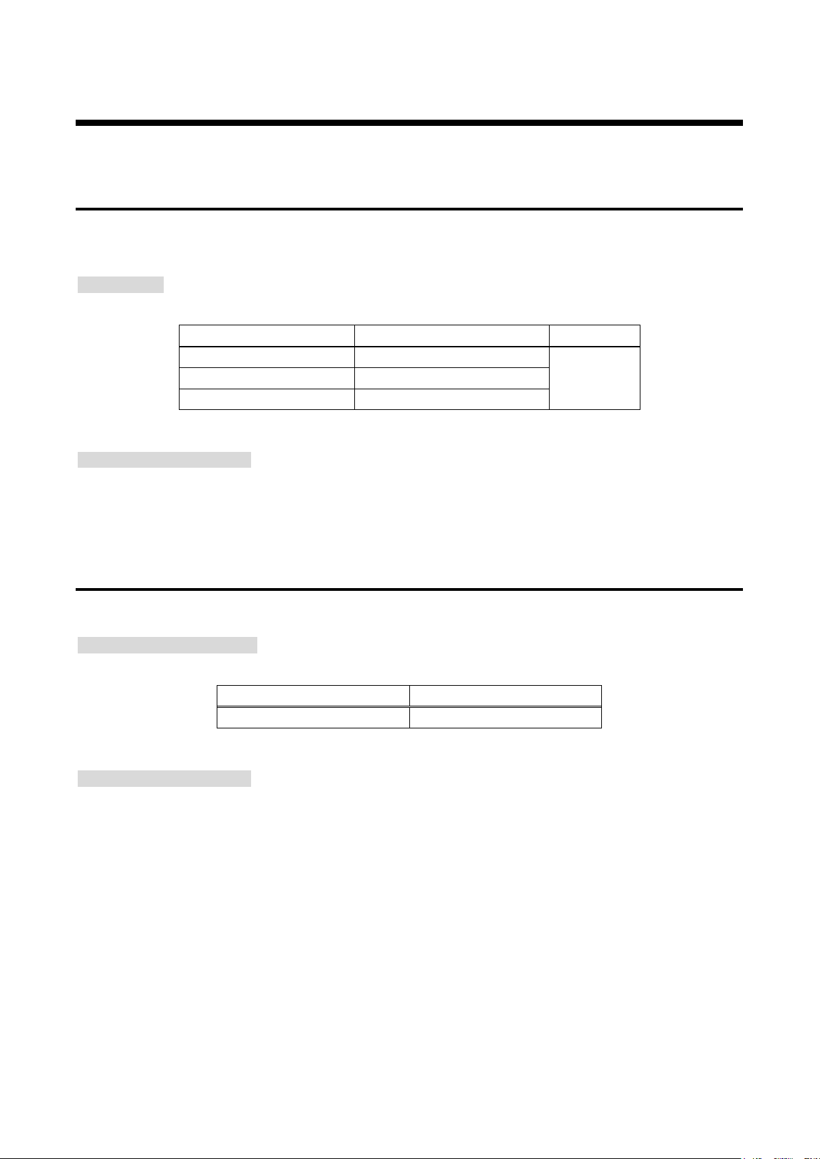
10.2 Setting LAN
10.2.1 LAN
The IP address can be obtained automatically by DHCP (Dynamic Host Configuration Protocol).
Static IP address, subnet mask, and default gateway can also be configured manually.
Setting value
[Table 10.2] Setting items of LAN communication
Setting item Setting value Default
IP address 0.0.0.0 to 255.255.255.255
Subnet mask 0.0.0.0 to 255.255.255.254
Default gateway 0.0.0.0 to 255.255.255.255
Communication command
@SIPS Setting LAN
@GIPS Getting LAN setting
Automatic
10.2.2 MAC address
You can display the NJR-AB08DAN’s MAC address.
Information to be displayed
[Table 10.3] MAC address
Item to be displayed Example
MAC address 0008E5690000
Communication command
@GMCC Getting MAC address
30
Page 31

NJR-AB08DAN User Guide/Command Guide
11 Command
11.1 Summary
A command consists of “@” (“40” in hexadecimal), 4 one-byte alphabetical characters (upper and lower
cases), followed by parameters (one-byte numbers). For some commands, multiple parameter values can be
specified or parameters are not necessary. Processing is executed by sending a delimiter at the end of the
command.
Example: @SACP,1,2,1,5
“,”( a comma, “2C” in hex) is indicated between a command and parameter and between two parameters.
“ ” is indicated as a delimiter CR LF (return+line feed, “0D” and “0A” in hex).
If an error occurs:
An error command is returned if an undefined command or wrong parameter is included.
Example: @AAA
@ERR,2
31
Page 32

NJR-AB08DAN User Guide/Command Guide
@ERR
Error status
33
Command
Function
Page
@GIPS / @SIPS
LAN
36
Command
Function
Page
@CLRC
Initialization
38
@RBTC
Reboot
38
11.2 Command l ist
■ Error status
Command Function Page
■ Setting audio
Command Function Page
@GACP / @SACP Audio crosspoint mode 34
@GACA / @SACA Assigning audio channel 35
■ Setting LAN
@GMCC MAC address 37
■ Advanced sett in g
32
Page 33
NJR-AB08DAN User Guide/Command Guide
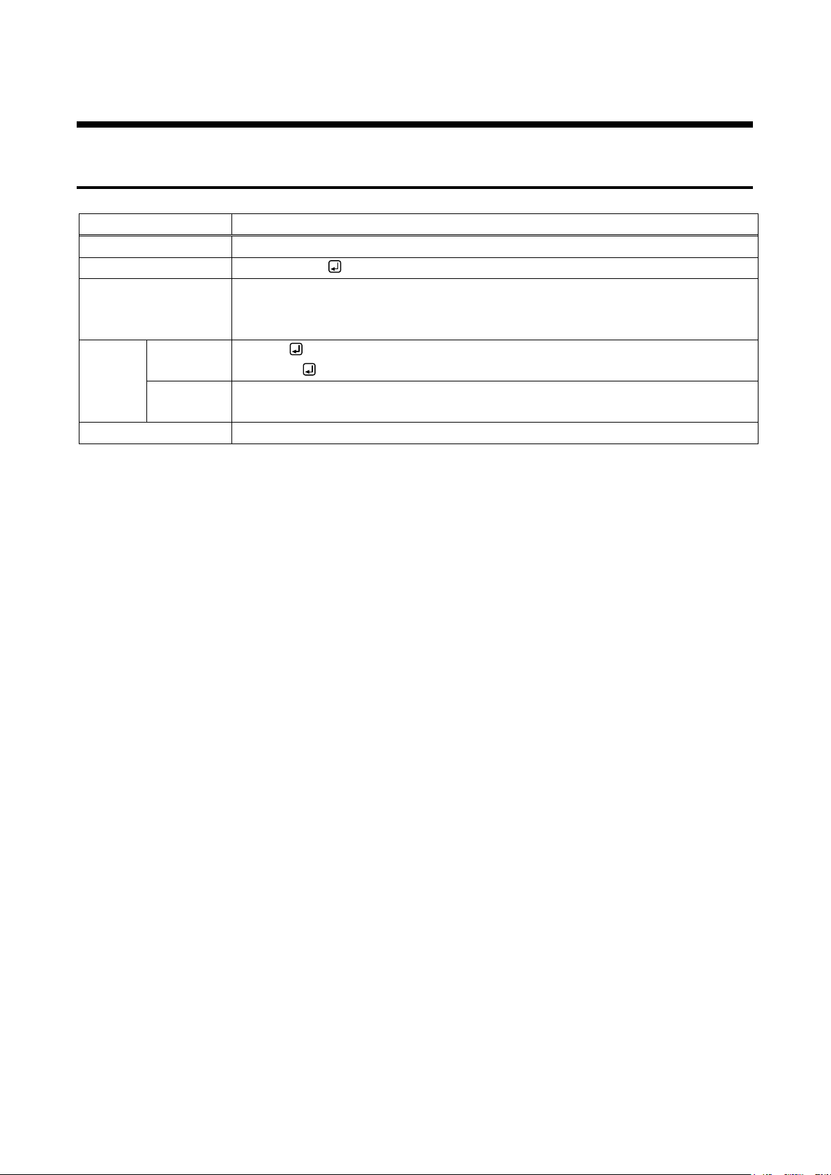
@ERR
Error status
@ERR, error
2 = Undefined command or wrong format
Getting
Command
@AAA
Command format error
Page -
11.3 Details of commands
11.3.1 Error status
Description Response in case the command is not executed
Response
Parameter error: Error status
1 = Erroneous parameter format or value
example
Description Sending @AAA command
Response
@ERR,2
33
Page 34

NJR-AB08DAN User Guide/Command Guide
@GACP / @SACP
Audio crosspoint mode
Getting
Command
@GACP, type_1, ch_1, reserved_1 (, type_2, ch_2, reserved_2
)
Response
@GACP, type_1, ch_1, reserved_1, mode_1 (, type_2, ch_2, reserved_2,
mode_2
)
mode_2
)
Response
@SACP, type_1, ch_1, reserved_1, mode_1 (, type_2, ch_2, reserved_2,
mode_2
)
Parameter
type_1-512: Type
1 to 512 = Channel 1 to Channel 512
reserved_1-512: Reservation
[Default] 2/2/2/2
Getting
Command
@GACP,1,2,1
@GACP,1,2,1,2
2/2/2/2
Setting
Command
@SACP,1,2,1,5
Description
Setting the audio crosspoint mode of Input channel 2 to 8/-/-/-
Page
P.27
11.3.2 Setting audio
・・・
・・・
Setting Command @SACP, type_1, ch_1, reserved_1, mode_1 (, type_2, ch_2, reserved_2,
・・・
・・・
1 = Input, 2 = Output
ch_1-512: Channel
“1” fixed
mode_1-512: Audio cross point mode
1 = 2/2/2/2,
2 = 4/2/2/-,
3 = 4/4/-/-,
4 = 6/2/-/-,
5 = 8/-/-/-
example
Description Getting the audio crosspoint mode of Input channel 2
example
Response
@SACP,1,2,1,5
Response
34
Page 35

NJR-AB08DAN User Guide/Command Guide
@GACA / @SACA
Assigning audio channel
@GACA, type_1, ch_1, reserved1_1 (, type_2, ch_2, reserved_2
)
reserved1_2, reserved2_2, mode_2
)
Response
@SACA, type_1, ch_1, reserved1_1, reserved2_1, mode_1 (, type_2, ch_2,
“1” fixed
ch_1-512: Input channel
reserved2_1-512: Reserv at ion
“0” fixed
number_1-512: The number of channels
mode_1-512: Assigning mode
example
Response
@GACA,1,2,1,2,1
Description
Getting the audio channel assignment of Input channel 2
example
Response
@SACA,1,2,1,0,7
Description
Assigning the audio channel of Input channel 2 to 7.1 Channels
(FL-FR-LFE-FC-RL-RR-RLC-RRC)
Page
P.29
Getting Command
Response @GACA, type_1, ch_1, reserved1_1, number_1, mode_1 (, type_2, ch_2,
reserved_2, number_2, mode_2・・・)
Setting Command @SACA, type_1, ch_1, reserved1_1, reserved2_1, mode_1 (, type_2, ch_2,
・・・
reserved1_2, reserved2_2, mode_2・・・)
Parameter type_1-512: Type
1 to 512 = Input channel 1 to Input channel 512
reserved1_1-512: Reserv at ion
“1” fixed
1 = 2 Channels (FL-FR),
2 = 2.1 Channels (FL-FR-LFE),
3 = 3.1 Channels (FL-FR-LFE-FC),
4 = 4.1 Channels (FL-FR-LFE-X-RL-RR),
5 = 5.1 Channels (FL-FR-LFE-FC-RL-RR),
6 = 6.1 Channels (FL-FR-LFE-FC-RL-RR-RC),
7 = 7.1 Channels (FL-FR-LFE-FC-RL-RR-RLC-RRC)
[Default] 2 Channels (FL-FR)
Getting
Command
@GACA,1,2,1
・・・
Setting
Command
2 Channels (FL-FR)
@SACA,1,2,1,0,7
35
Page 36
NJR-AB08DAN User Guide/Command Guide
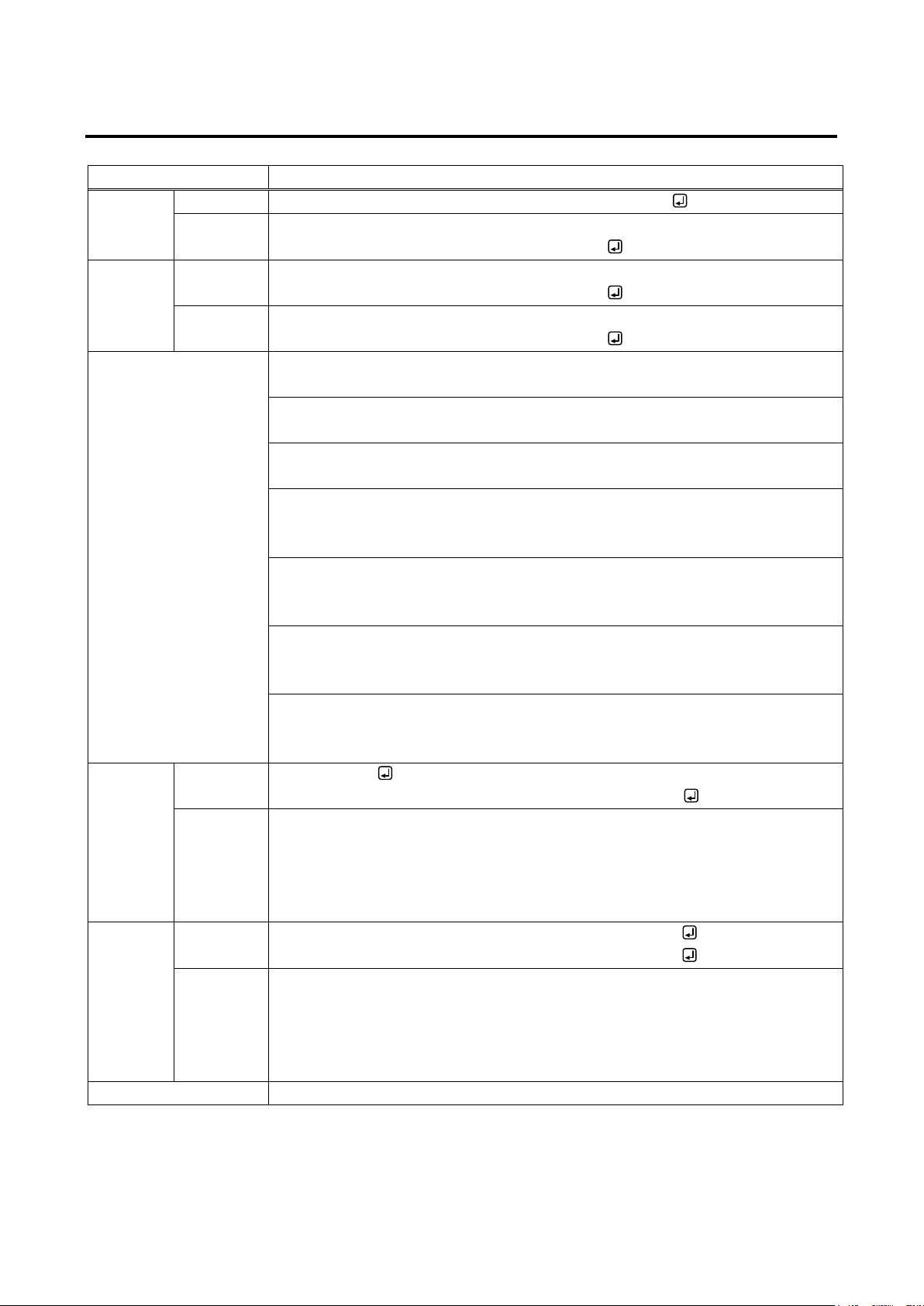
@GIPS / @SIPS
LAN
Getting
Command
@GIPS, type_1, ch_1, port_1 (,type_2, ch_2, port_2
)
Response
@GIPS, type_1, ch_1, port_1, mode_1, ip_1, mask_1, gateway_1 (,type_2, ch_2,
port_2, mode_2, ip_2, mask_2, gateway_2
)
port_2, mode_2, ip_2, mask_2, gateway_2
)
Response
@SIPS, type_1, ch_1, port_1, mode_1, ip_1, mask_1, gateway_1 (,type_2, ch_2,
port_2, mode_2, ip_2, mask_2, gateway_2
)
Parameter
type_1-512: Type
1 to 512 = Channel 1 to Channel 512
port_1-512: Connector
ip_1-512: IP address
[Default] Getting automatically
mask_1-512: Subnet mask
[Default] Getting automatically
gateway_1-512: Default gateway
[Default] Getting automatically
Getting
example
Command
Response
@GIPS,1,1,1,1,192.168.3.2,255.255.255.0,192.168.3.254
Description
Getting the LAN setting of Input channel 1
- Default gateway : 192.168.3.254
Setting
Command
@SIPS,1,1,1,1,192.168.3.2,255.255.255.0,192.168.3.254
@SIPS,1,1,1,1,192.168.3.2,255.255.255.0,192.168.3.254
- Default gateway : 192.168.3.254
Page
P.30
11.3.3 Setting LAN
・・・
・・・
Setting Command @SIPS, type_1, ch_1, port_1, mode_1, ip_1, mask_1, gateway_1 (,type_2, ch_2,
・・・
・・・
1 = Input, 2 = Output
ch_1-512: Channel
“1” fixed
mode_1-512: Mode
0 = Automatic (DHCP) [Default], 1 = Static
“0” is selected, the following three parameters will be invalid.
0 to 255 = 8 bit (in decimal) x 4 combinations
0 to 255 = 8 bit (in decimal) x 4 combinations
0 to 255 = 8 bit (in decimal) x 4 combinations
@GIPS,1,1,1
- Mode : Static
- IP address : 192.168.3.2
- Subnet mask : 255.255.255.0
example
Description Setting the LAN of Input channel1 as follows:
Response
- Mode : Static
- IP address : 192.168.3.2
- Subnet mask : 255.255.255.0
36
Page 37

NJR-AB08DAN User Guide/Command Guide
@GMCC
MAC address
@GMCC, type_1, ch_1, port_1 (, type_2, ch_2, port_2
)
@GMCC, type_1, ch_1, port_1, mac_1 (, type_2, ch_2, port_2, mac_2
)
1 to 512 = Channel 1 to Channel 512
port_1-512: Connector
00 to FF = 8 bit (in hex) x 6 combinations
Getting
Command
@GMCC,1,1,1, 0008E5690000
Description
Getting the MAC address of Input channel 1
Page
P.30
Getting Command
Response
Parameter type_1-512: Type
1 = Input, 2 = Output
ch_1-512: Channel
“1” fixed
mac_1-512: MAC address
@GMCC,1,1,1
example
Response
00:08:E5:69:00:00
・・・
・・・
37
Page 38

NJR-AB08DAN User Guide/Command Guide
@CLRC
Initialization
Setting
Command
@CLRC, type _1, ch_1, reserved_1, comm_setting_1, (,type _2, ch_2,
reserved_2, comm_setting_2
)
Parameter
type_1-512: Type
1 = Input, 2 = Output
ch_1-512: Input channel
“1” fixed
comm _setting_1-512: Communication setting (initializing LAN and RS-232C)
example
Response
@CLRC,1,2,1,0
Description
Initializing settings of Input channel 2, except for communication setting
Page
P.25
@RBTC
Reboot
1 = Input, 2 = Output
ch_1-512: Channel
example
Response
@RBTC,1,2,1
Description
Rebooting the Input channel 2
Page
P.25
11.3.4 Advanced setting
reserved_2, comm_setting_2・・・)
Response @CLRC, type _1, ch_1, reserved_1, comm_setting_1 (,type _2, ch_2,
1 to 512 = Input channel 1 to Input channel 512
reserved_1-512: Reservation
0 = Disabled [Default], 1 = Enabled
Setting
Command
@CLRC,1,2,1,0
・・・
Setting Command
Response
Parameter type_1-512: Type
Setting
Command
@RBTC, type_1, ch_1, reserved_1 (,type_2, ch_2, reserved_2・・・)
@RBTC, type_1, ch_1, reserved_1 (,type_2, ch_2, reserved_2・・・)
1 to 512 = Channel 1 to Channel 512
reserved_1-512: Reservation
“1” fixed
@RBTC,1,2,1
38
Page 39

12 Product specification
Item
Description
1 input
Connector: 2 LCs
1 input
Connector: 2 RJ-4 5s (P rim ary/Secondary) (*1)
1 output
Connector: 2 LCs
1 output
Connector: 2 RJ-4 5s (P rim ary/Secondary) (*1)
Duplex fiber cable
SFP+ optical transceiver
SFP+ optical transceiver for Multimode : PC polishing (recommended)
SPC *APC is not supported
Multimode fiber (OM3) : Up to 984 ft. (300 m)
Singlemode fiber (OS1) : Up to 24.85 mi. (40 km, optional)
Cable
CAT.5E HDC, Cat5e UTP/STP, Cat6 UTP/STP, Cat6A UTP/STP
Transmission
distances
Up to 328 ft. (100 m)
Input : 100 - 240 VAC ± 10%, 50 Hz/60 Hz ± 3 Hz
Output : DC 12 V 3 A (A dedicated AC adapter is provided)
Power
consumption
8.3 (W) × 1.2 (H) × 3.9 (D)” (210 (W) × 30 (H) × 100 (D) mm)
(Almost equivalent to half rack wide, 1U high) (Excluding connectors and the like)
Weight
1.5 lbs. (0.7 kg)
Operating : 32°F to 104°F (0°C to +40°C)
Storage : -4°F to +176°F (-20°C to +80°C)
Humidity
Operating/Storage: 20% to 90% (Non Condensing)
Format: IP-NINJAR protocol
IP-NINJAR
network audio
Input
Dante
network audio
IP-NINJAR
network audio
Output
Dante
network audio
Cable
Sampling frequency: 44.1 kHz to 192 kHz, Sample size: 24 bit
Maximum audio stream: 4 streams
Maximum audio input channel: 8 channels
Format: Dante protocol
Sampling frequency: 44.1 kHz to 192 kHz, Sample size: 24 bit
Maximum audio input channel: 8 channels
Format: IP-NINJAR protocol
Sampling frequency: 44.1 kHz to 192 kHz, Sample size: 24 bit
Maximum audio stream: 4 streams
Maximum audio output channel: 8 channels
Format: Dante protocol
Sampling frequency: 44.1 kHz to 192 kHz, Sample size: 24 bit
Maximum audio output channel: 8 channels
NJR-AB08DAN User Guide/Command Guide
IP-NINJAR
Cable for
extension
General
*1 These RJ-45 connectors are only for Dante format.
*2 We do not recommend other polishing methods because it increases the return loss.
*3 The maximum extension distance is measured under the following conditions: Fiber that is polished by a recommended method is used; there is no interconnection; it does not
exceed the allowable bending radius.
network audio
Dante
network audio
Polishing (*2)
Transmission
distances (*3)
AC adapter
Dimensions
Temperature
SFP+ optical transceiver for Singlemode : UPC polishing (recommended),
Singlemode fiber (OS1) : Up to 6.21 mi. (10 km)
About 10 Watts
39
Page 40

NJR-AB08DAN User Guide/Command Guide
1
Does the same problem occur at all connectors?
Yes or No
13 Troubleshooting
In case the NJR-AB08DAN does not work correctly, please check the following items first. Also refer to
manuals for connected devices as well, since they may possibly be the cause of the problem.
・ Are the NJR-AB08DAN and all devices plugged in and powered on normally?
・ Are cables connected correctly?
・ Are there no loose connections?
・ Are correct cables for NJR-AB08DAN being used?
・ Are signal specifications of connected devices matched to each other?
・ Are there any nearby objects that may cause noise?
If additional assistance is required, pl eas e perform the following tests and then contact us.
No. Checking items Result
Connect the devices using genuine cables without connecting the
2
NJR-AB08DAN.
The problem still cannot be solved? Please contact us for assistance.
Yes or No
40
Page 41

NJR-AB08DAN User Guide/Command Guide
Headquarters
IDK Corporation
Email: [email protected] URL: http://www.idkav.com
Email: [email protected] URL: http://www.idkav.com
TEL: +49-2102-578-301-0
Email: [email protected] URL: http://www.idkav.com
TEL: +81-46-259-6920 FAX: +81-46-259-6930
Email: [email protected] URL: http://www.arvanics.com
User Guide/Command Guide of NJR-AB08DAN
Ver.1.0.0
Issued on: 22 July 2019
USA
Europe
Product information
Support
7-9-1 Chuo, Yamato-s hi, Kanagawa-pref.
242-0021 JAPAN
TEL: +81-46-200-0764 FAX: +81-46-200-0765
IDK America Inc.
72 Grays Bridge Road Suite 1-C, Brookfield, CT 06804
TEL: +1-203-204-2445
IDK Europe GmbH
Lise-Meitner-Str. 6, D-40878 Ratingen
Arvanics Corporation
7-9-1 Chuo, Yamato-s hi, Kanagawa-pref.
242-0021 JAPAN
Information in this document is subject to change without notice.
©2019 IDK Corporation, all rights reserved. All trademarks mentioned are the property of their
respective owners.
41
 Loading...