

Page 1
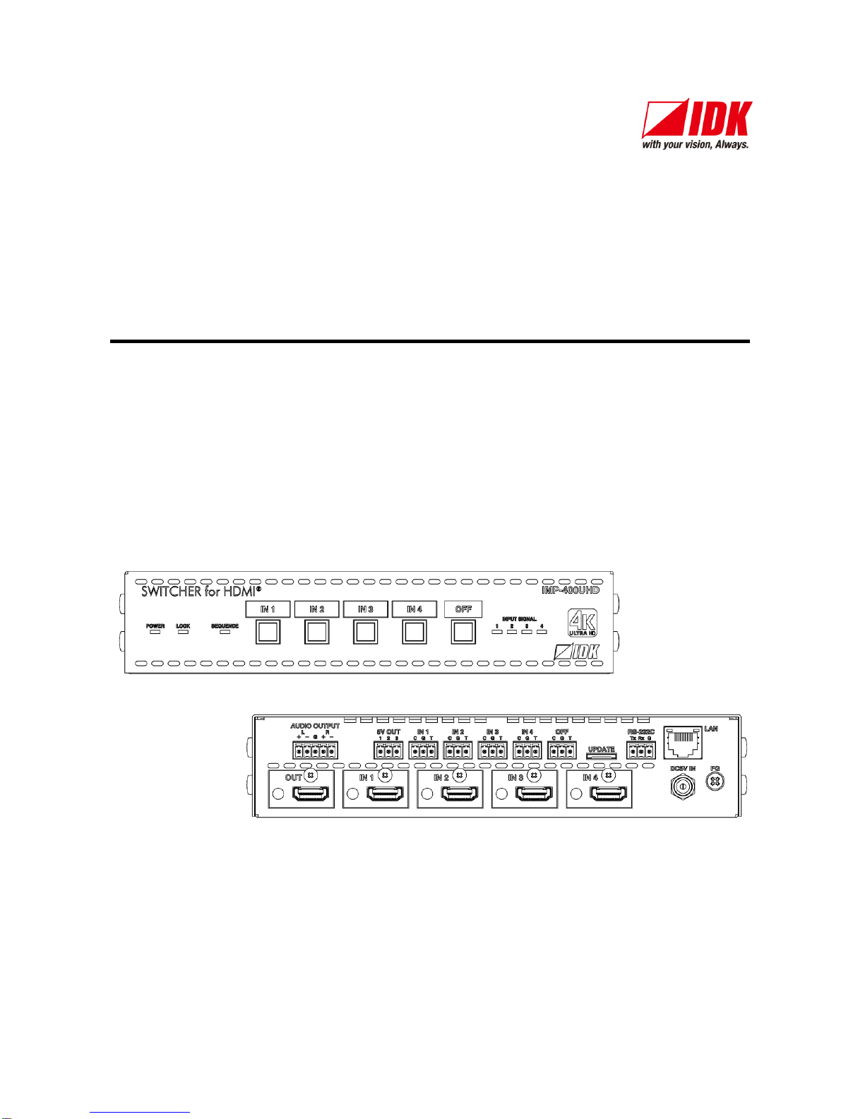
4K@60 and HDCP2.2 supported 4 x 1 HDMI Switcher
IMP-400UHD
<Command Reference Guide>
Ver.1.0.0
● Thank you for choosing our product.
● To ensure the best performance of this product, please read this User’s Guide fully and carefully before
using it and keep this manual together with the product for reference as needed.
IDK Corporation
Page 2

IMP-400UHD Command Guide
2
Trademarks
● The terms HDMI and HDMI High-Definition Multimedia Interface, and the HDMI Logo are trademarks or
registered trademarks of HDMI Licensing Administrator, Inc. in the United States and other countries.
● Blu-ray Disc and Blu-ray are trademarks of Blu-ray Disc Association.
● Anti Snow and Connection Reset are registered trademarks of IDK in Japan.
● All other company and product names mentioned in this manual are either registered trademarks or
trademarks of their respective owners. In this manual, the “®” or “™” marks may not be specified.
Page 3

IMP-400UHD Command Guide
3
Before reading this manual
● All rights reserved.
● Some of the contents in this user’s guide such as the appearance of diagrams, menu operations,
communication commands, and so on may differ between products depending on the specific version.
● This Command guide is subject to change without notice. You can download the latest version from IDK’s
website at: http: //www.idkav.com
Page 4

IMP-400UHD Command Guide
4
Table of Contents
1 About this Guide .................................................................................................................................... 5
2 Specification and Setup of Communication ................................ ............................................................ 6
2.1 RS-232C communication .................................................................................................................. 6
2.1.1 RS-232C connector specification .............................................................................................. 6
2.1.2 RS-232C communication specification...................................................................................... 6
2.1.3 Setting up RS-232C communication ......................................................................................... 7
2.2 LAN communication ......................................................................................................................... 8
2.2.1 LAN connector specification ..................................................................................................... 8
2.2.2 LAN communication specification ............................................................................................. 8
2.2.3 Setting up LAN communication................................................................................................. 9
2.2.4 The number of TCP-IP connections ................................ ......................................................... 10
3 Command ............................................................................................................................................11
3.1 Command outline ........................................................................................................................... 11
3.2 Command list ................................................................................................................................ . 12
3.3 Detailed description ................................ ........................................................................................ 14
3.3.1 Error status .............................................................................................................................14
3.3.2 Selecting input channel ...........................................................................................................14
3.3.3 Input setting ............................................................................................................................15
3.3.4 Switching setting .....................................................................................................................16
3.3.5 Output settings ........................................................................................................................21
3.3.6 Audio setting ...........................................................................................................................22
3.3.7 Contact input ...........................................................................................................................23
3.3.8 EDID .......................................................................................................................................24
3.3.9 RS-232C communication .........................................................................................................29
3.3.10 LAN communication ................................................................................................................30
3.3.11 Startup settings .......................................................................................................................32
3.3.12 Other settings ..........................................................................................................................33
3.3.13 Displaying status .....................................................................................................................34
Page 5
IMP-400UHD Command Guide
5
1 About this Guide
This guide contains information of communication commands that control the IMP-400UHD via RS-232C or
LAN communication.
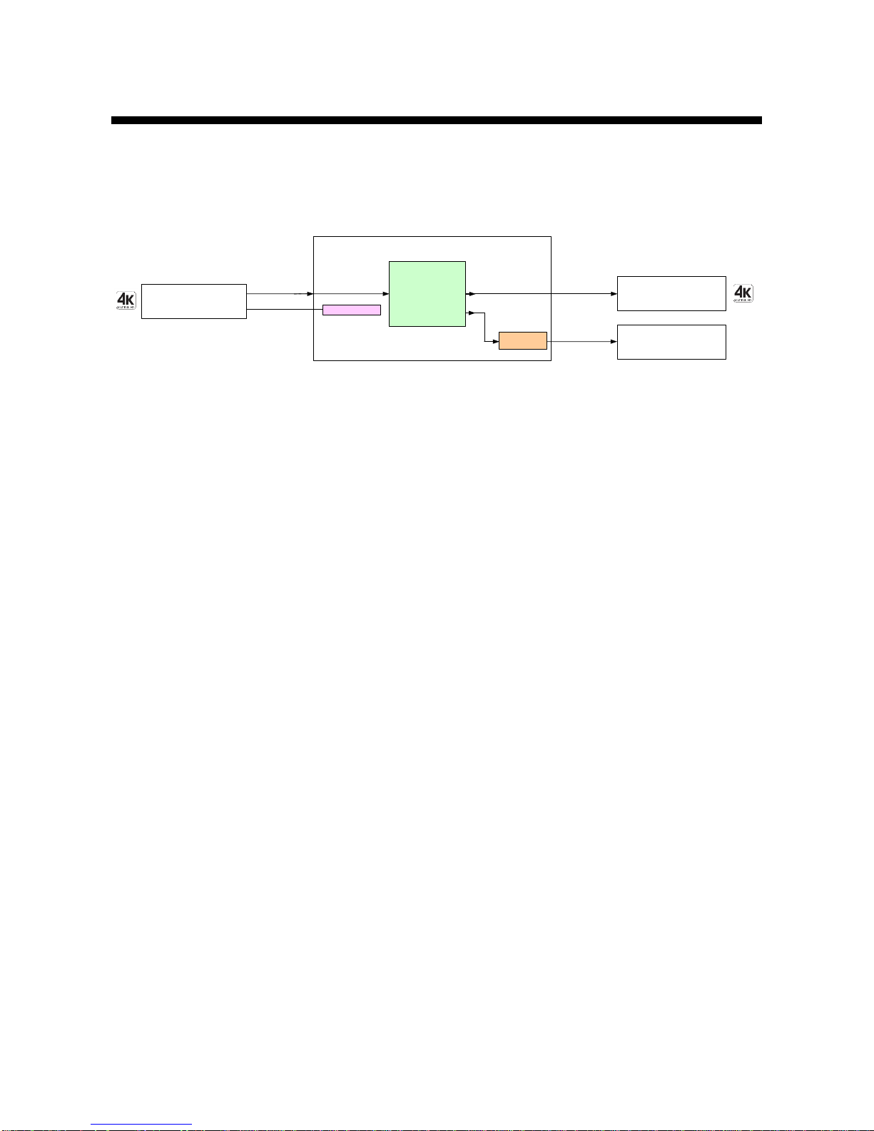
The IMP-400UHD is a 4x1 HDMI signal switcher supporting 4K@60 video signal and HDCP2.2.
Digital audio signal is converted into analog and output from the AUDIO OUTPUT connector.
EDID emulator
IMP-400UHD
Analog audo
L/R Balanced / Unbalanced
Output
1
Up to 98.4 ft. (30 m)*
Digital video/audio
HDMI DVI
Inputs
4
Digital video/audio
HDMI DVI
Output
1
Video・Audio
switch
*Maximum cable distance
1080p@60: up to 98.4 ft. (30 m)
4K@60: up to 39.4 ft. (12 m) when 18 Gbps high-speed transmission cable is used.
Video / Audio
Audio
D/A
conversion
Up to 98.4 ft. (30 m)*
[Figure 1.1] Diagram
Page 6
IMP-400UHD Command Guide
6
2 Specification and Setup of Communication
2.1 RS-232C communication
2.1.1 RS-232C connector specification
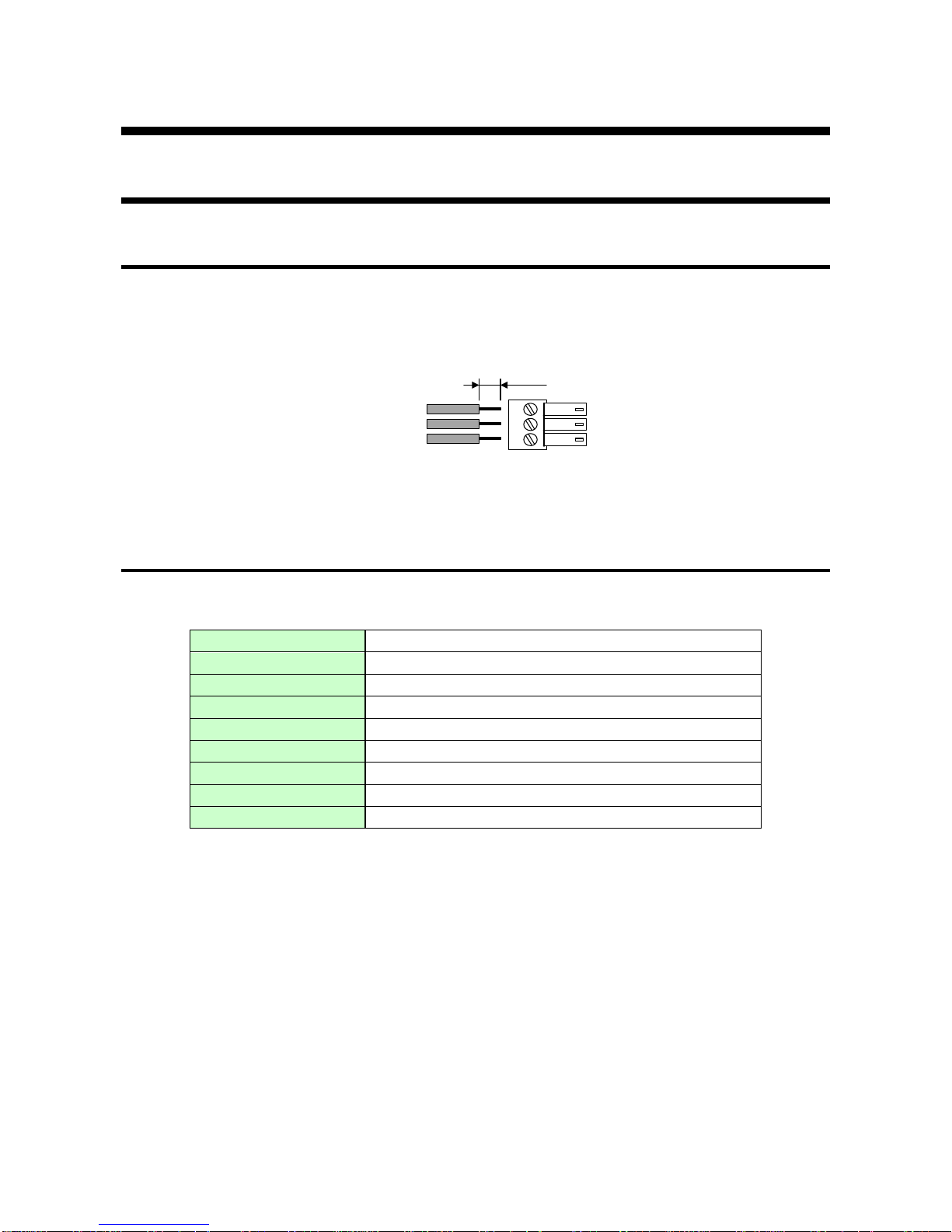
Connect the RS-232C cable to the provided 3-pin terminal block, and then insert it to the RS-232C connector.
AWG28 to AWG16 conductor gauge is recommended for optimal performance.
The recommended wire strip length is 7 mm/0.28 inch.
If connecting to the D-sub9, please short RTS, CTS, DTR, and DSR.
Tx
Rx
GND
RS-232C Tx
RS-232C Rx
GND
Up to 0.28 in. (7 mm)
[Figure 2.1] Connecting RS-232C cable to 3-pin terminal block connector
2.1.2 RS-232C communication specification
[Table 2.1] RS-232C specification
Standard
RS-232C
Baud rate [bps]
4800 / 9600 / 19200 / 38400 [bps]
Data bit length [bit]
7 / 8
Parity check
NONE, EVEN, ODD
Stop bit [bit]
1 / 2
X parameter
Invalid
Flow control
None
Delimiter
CR LF (Carriage return and line feed, 0D and 0A in hex)
Communication method
Full duplex
Page 7
IMP-400UHD Command Guide
7
2.1.3 Setting up RS-232C communication
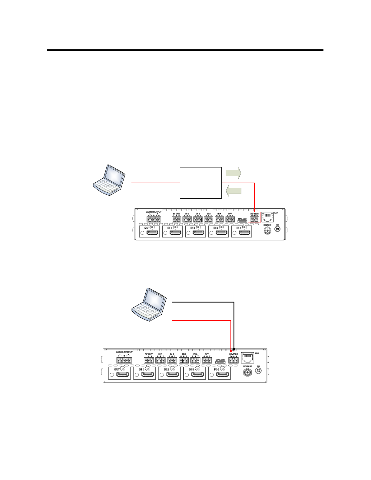
Follow the procedure below to set RS-232C communication between the IMP-400UHD and control devices.
(1) Connect the IMP-400UHD and the control device via an appropriate cable.
(2) Set the RS-232C communication as follows:
・RS-232C communication: Baud rate, data bit length, parity check, and stop bit
【Reference: User’s Guide】
(3) For the control device, set the same values in the same way as RS-232C communication (baud rate, data
bit length, parity check, and stop bit) in step (2) above.
(4) Send a communication command from the control device to the IMP-400UHD in order to check the control
status of the IMP-400UHD.
Step (3)
Laptop
Step (2)
Step (1)
RS-232C cable
Step (4)
Communication
command
(Control command)
[Figure 2.2] RS-232C communication
■ RS-232C communication operation example
Laptop
RS-232C cable
Controlling IMP-400UHD via
communication command
[Figure 2.3] Operation example: RS-232C communication
Page 8
IMP-400UHD Command Guide
8
2.2 LAN communication
2.2.1 LAN connector specification
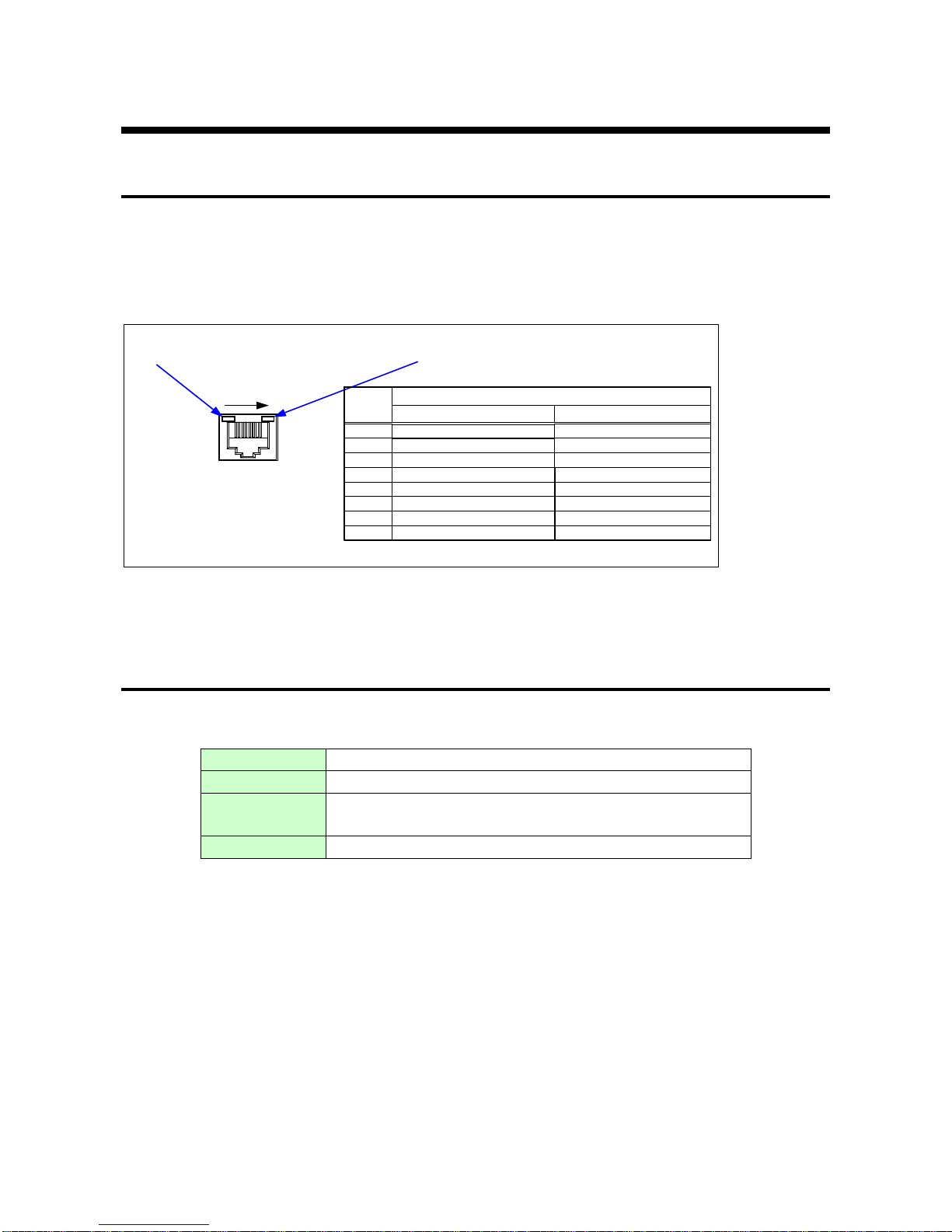
The IMP-400UHD supports Auto MDI/MDI-X, which distinguishes/switches straight and cross cables
automatically.
Pin assignments of LAN connector:
81
LAN connector
8-pin RJ-45 connector
(Rear panel)
Illuminates green while link is established.
Blinks green while data is being sent/received.
Illuminates orange if the send/receive rate is 100 Mbps.
Goes off if it is 10 Mbps.
RX+: Received Data+
N.C: Not connected
TX+: Transmitted Data+
Pin #
1
3
2
4
6
5
7
Signal Name
TX-: Transmitted Data-
N.C: Not connected
RX-: Received Data-
N.C: Not connected
N.C: Not connected
MDI
TX+: Transmitted Data+
N.C: Not connected
RX+: Received Data+
RX-: Received Data-
N.C: Not connected
TX-: Transmitted Data-
N.C: Not connected
N.C: Not connected
MDI-X
8
[Figure 2.4] LAN connector specification
2.2.2 LAN communication specification
[Table 2.2] Specification of LAN communication
Physical layer
10BASE-T (IEEE802.3i)/100Base-TX (IEEE802.3u)
Network layer
ARP, IP, ICMP
Transport layer
TCP
Port used for command control: 23, 1100, 6000 to 6999
Application layer
HTTP, TELNET
Note: Up to 7 connections can be used simultaneously.
Page 9
IMP-400UHD Command Guide
9
2.2.3 Setting up LAN communication
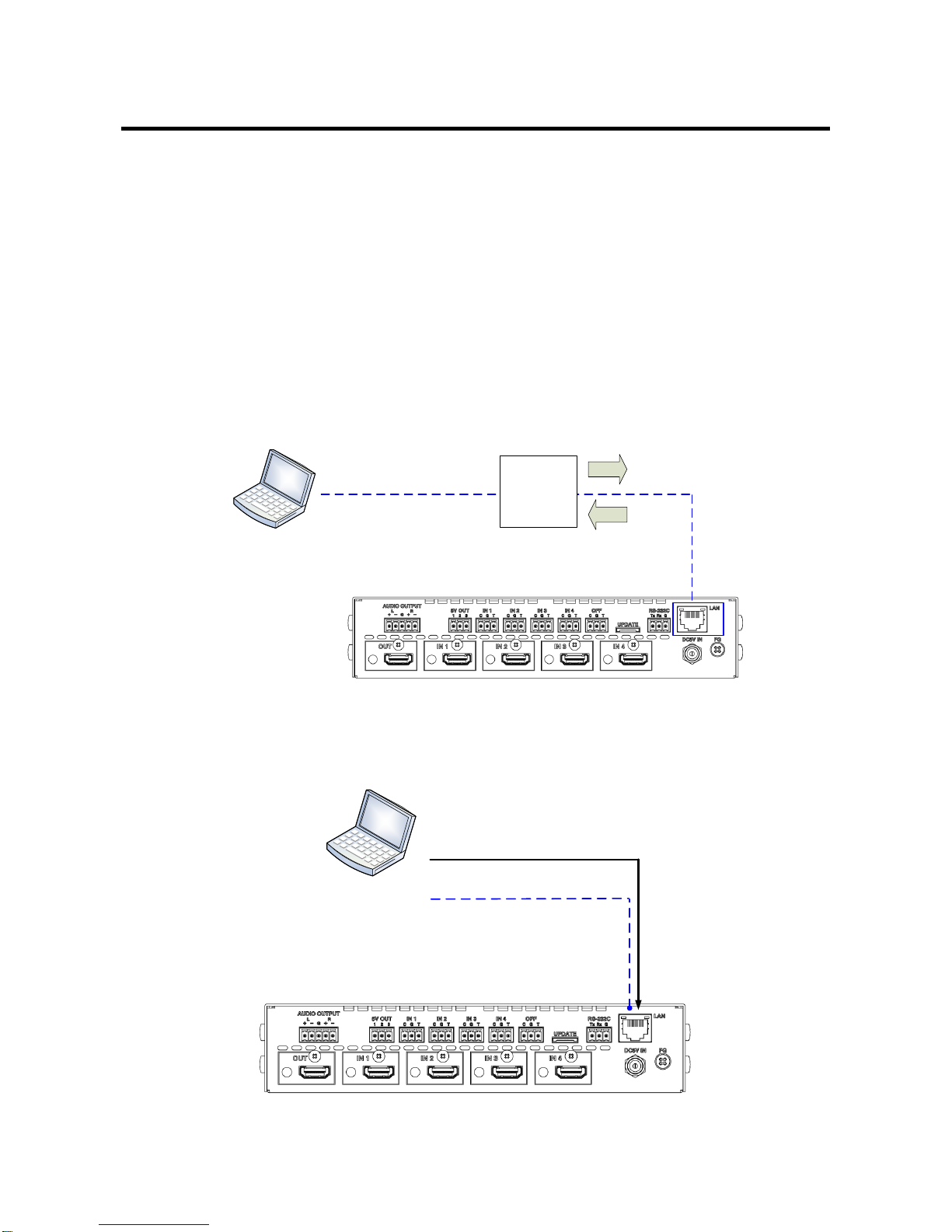
Follow the procedure below to set LAN communication between the IMP-400UHD and control devices.
(1) Connect the IMP-400UHD and the control device via a LAN cable.
(2) Set up LAN communication as follows:
・Set IP address and subnet mask
・TCP pot number: 23, 1100, 6000 to 6999
【Reference: User’s Guide】
(3) Establish the connection from the control device to the IP address and TCP port that are set to the
IMP-400UHD in step (2) above.
(4) Send a communication command from the control device to the IMP-400UHD in order to check the
control status of the IMP-400UHD.
Step (3)
Laptop
Step (2)
Step (1)
LAN cable
Step (4)
Communication
command
(Control device)
[Figure 2.5] Control via LAN communication
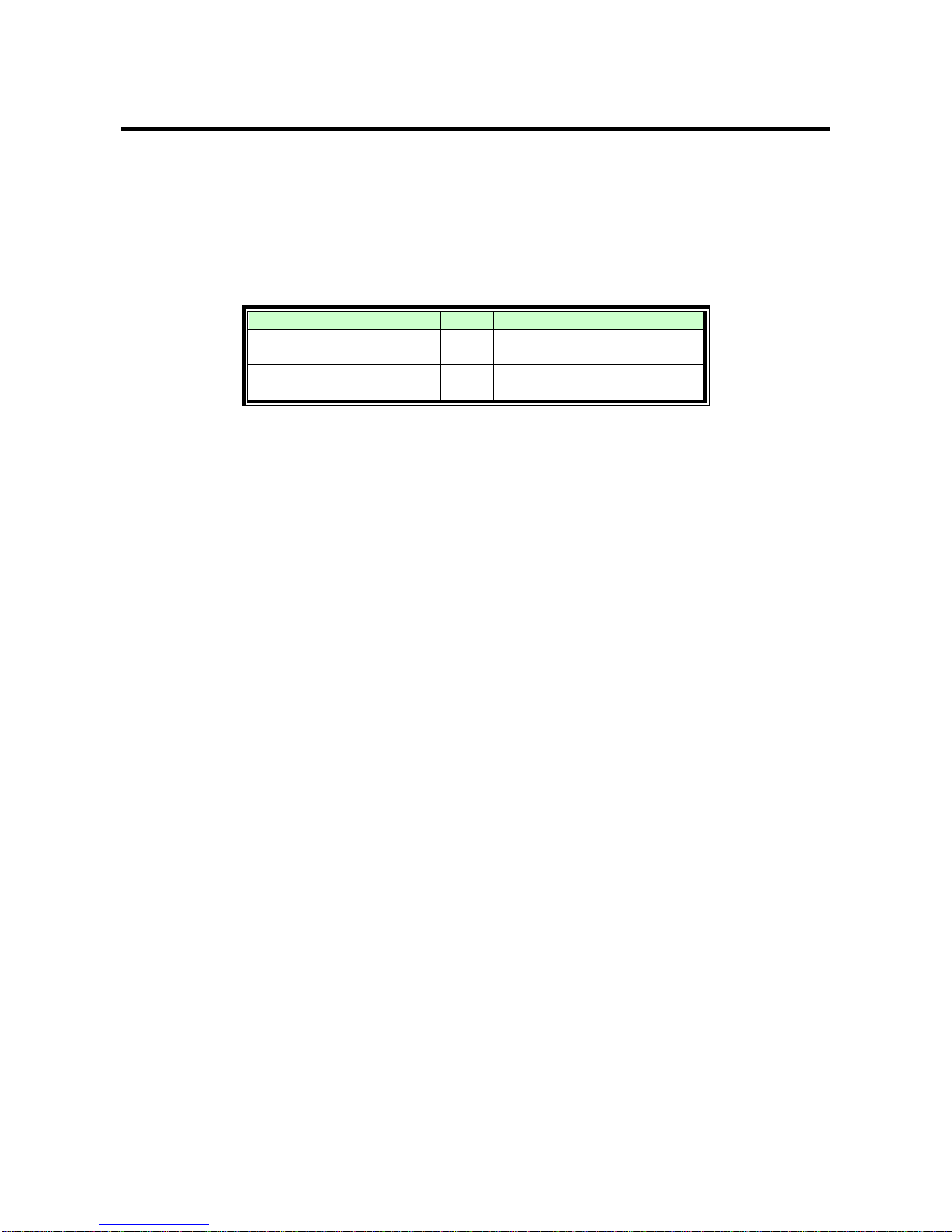
■ LAN communication operation example
Laptop
LAN cable
Controlling IMP-400UHD via
communication command
[Figure 2.6] Operation example: LAN communication
Page 10
IMP-400UHD Command Guide
10
2.2.4 The number of TCP-IP connections
The IMP-400UHD series can connect up to seven connections (seven ports) simultaneously. If the
IMP-400UHD is controlled from eight or more PCs, they may not be connected to the IMP-400UHD, since the
number of connections that can be used is limited.
If you use eight connections or more, execute TCP-IP connection/close every time the communication
command is sent or received from the software of user’s side. It makes IMP-400UHD’s ports occupied or
released so that eight or more connections can be connected logically.
[Table 2.3] Increasing connections
Your PC’s software
IMP-400UHD
TCP-IP connection
→
(Occupied by 1 port)
Send command (@xxx)
→ ← Send back command (@xxx)
TCP-IP close
→
(Release 1 port)
Note:
If any command is not sent from the PC side to the IMP-400UHD for 30 seconds, the IMP-400UHD
disconnects the connection to avoid the limitation problem on the number of connections. As a result,
connection needs to be established again from the PC side after the current connection of the PC is
disconnected.
(Since the number of ports in the IMP-400UHD is seven, ports are occupied permanently if the PC is turned
off while connections are valid. To prevent this, the IMP-400UHD disconnects connections if no
communication command is sent from the PC side.)
Page 11
IMP-400UHD Command Guide
11
3 Command
3.1 Command outline
A command consists of “@” (“40” in hexadecimal), 3 one-byte alphabetical characters (upper and lower
cases), and parameters (one-byte numbers*). For some commands, several parameters can be specified or
no parameter is required. Processing is executed by sending a delimiter at the end of the command.
Example: @SSW,2
“,”( a comma, “2C” in hexadecimal) is indicated between a command and parameter and between two
parameters.
: delimiter CR LF (return+line feed, “0D” and “0A” in hex)
■ If there is an error:
An error command is returned if an undefined command or wrong parameter is included.
Example:@SSW,5
@ERR,1
■ Using as HELP:
If only delimiter is sent, command list as the help command is returned.
Example:
--------------- HELP (1/8) ---------------
(CHANNEL SELECT Command)
@GSW / @SSW : Get/Set Input Channel
@GCP / @IOS : Get/Set Input Channel
--------------- HELP (2/8) ---------------
(INPUT SETTING Command)
@GDT / @SDT : Get/Set Digital Input Signal Detect Time
@GHE / @SHE : Get/Set HDCP Input Enable
@GAU / @SAU : Get/Set Auto Switching On
@GOF / @SOF : Get/Set Auto Switching Off
Page 12
IMP-400UHD Command Guide
12
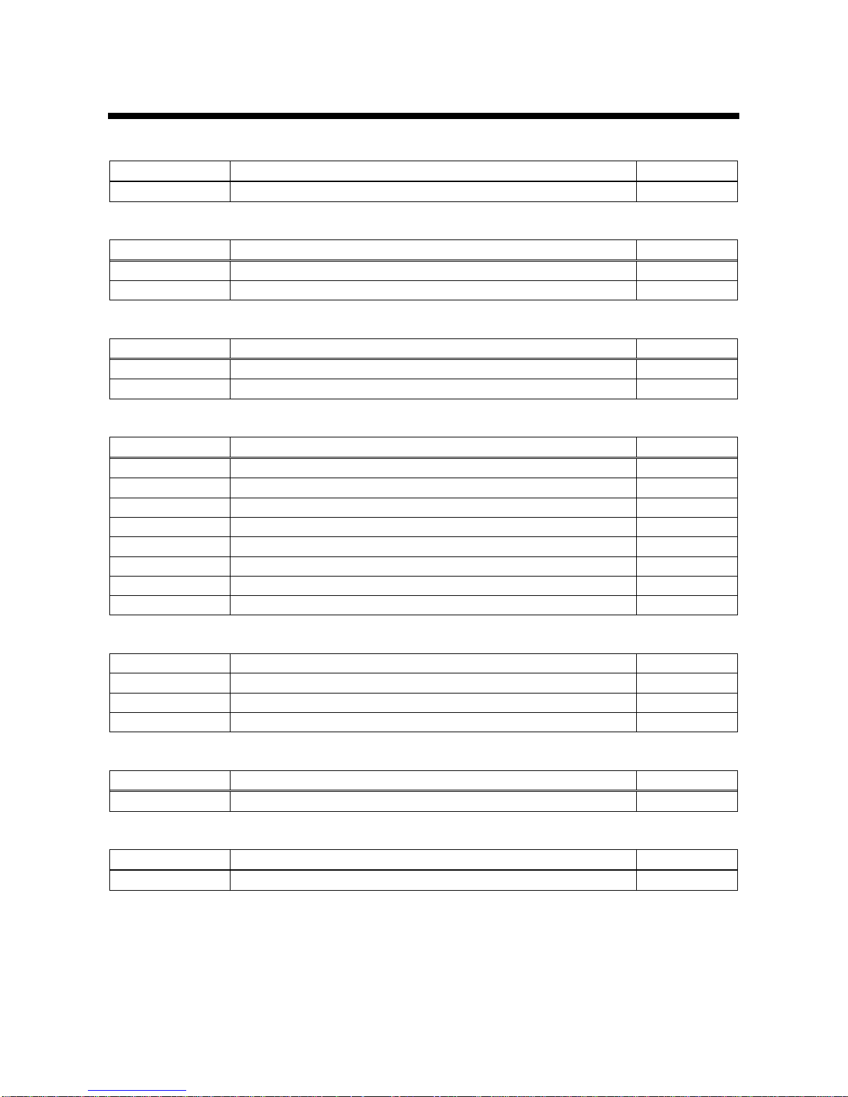
3.2 Command list
■ Error status
Command
Feature
Page
@ERR
Error status
14
■ Input channel setting
Command
Feature
Page
@GSW / @SSW
Input channel
14
@GCP / @IOS
Input channel switching (For the previous model)
15
■ Input setting
Command
Feature
Page
@GDT / @SDT
No-signal-input monitoring
15
@GHE / @SHE
HDCP input enabled/disabled
16
■ Switching setting
Command
Feature
Page
@GAU / @SAU
Priority of input channel automatic switching (OFF to ON)
16
@GOF / @SOF
Priority of input channel automatic switching
17
@GMT / @SMT
Masking time after automatic switching of input channel
17
@GST / @SST
Sequence switching mode
18
@GSQ / @SSQ
Target channel for sequence switching mode
18
@GIT / @SIT
Switching interval for sequence switching mode
19
@GSD / @SSD
Input detection
19
@GSC / @SSC
Starting channel of sequence switching mode
20
■ Output setting
Command
Feature
Page
@GDM / @SDM
Output mode
21
@GCO / @SCO
Sink device EDID check
21
@HAU
HDCP re-encryption
22
■ Audio setting
Command
Feature
Page
@GAM / @SAM
Audio output mute
22
■ Contact input
Command
Feature
Page
@GFP / @SFP
Chattering reduction time of contact input
23
Page 13
IMP-400UHD Command Guide
13
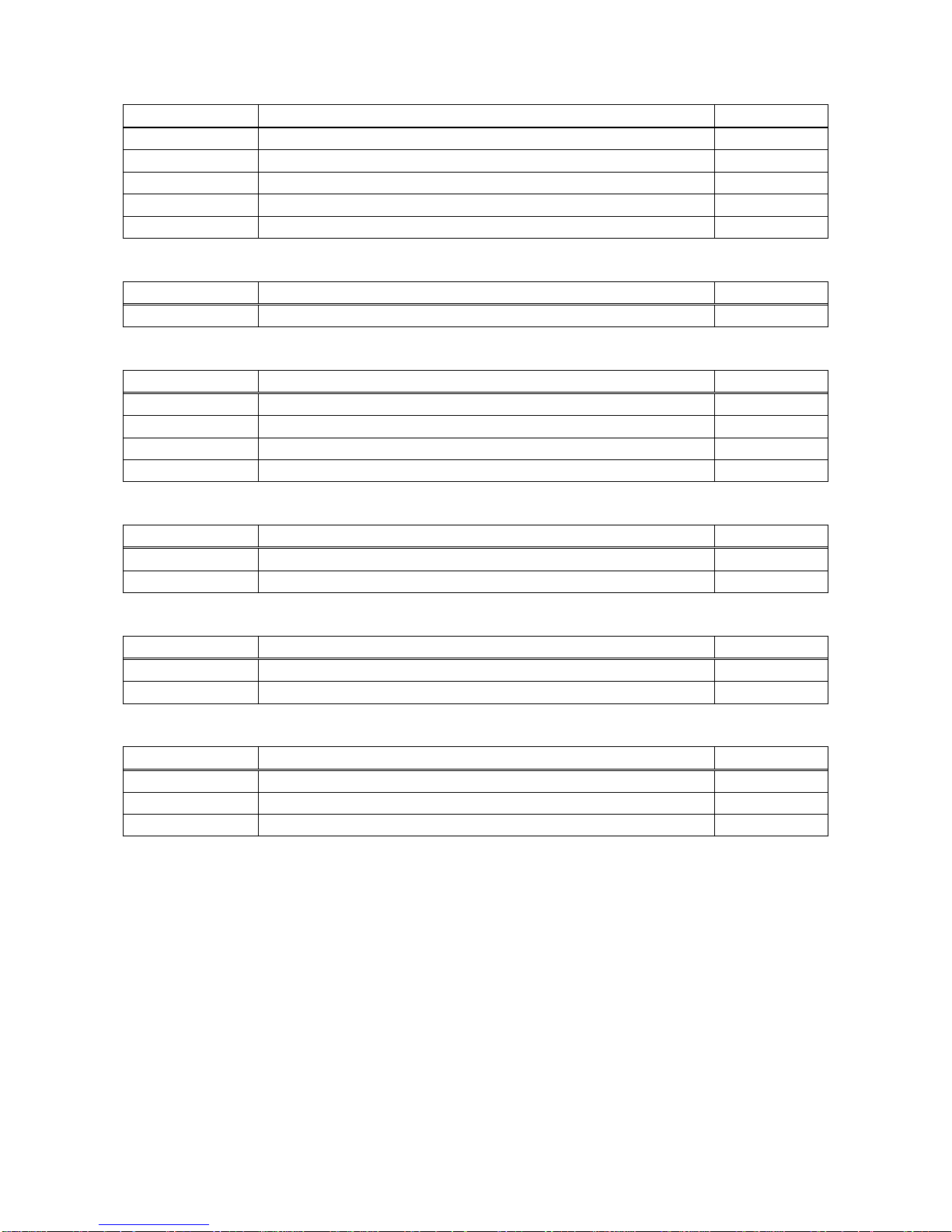
■ EDID
Command
Feature
Page
@GVF / @SVF
EDID
24
@GDI / @SDI
Deep Color input
25
@GAF / @SAF
Audio format
26
@GSP / @SSP
The number of speakers
28
@RME
EDID copy
28
■ RS-232C setting
Command
Feature
Page
@GCT / @SCT
RS-232C
29
■ LAN setting
Command
Feature
Page
@GIP / @SIP
IP address
30
@GSB / @SSB
Subnet mask
30
@GLP / @SLP
TCP port number
31
@GMC
MAC address
31
■ Startup setting
Command
Feature
Page
@GMU / @SMU
Startup input channel
32
@GSO / @SSO
Startup operation lock
32
■ Other setting
Command
Feature
Page
@GLS / @SLS
Operation lock
33
@GBZ / @SBZ
Buzzer
33
■ Status display
Command
Feature
Page
@GSS
Displaying input signal status / sink device status
34
@GES
Monitor’s EDID
38
@GIV
Version
39
Page 14
IMP-400UHD Command Guide
14
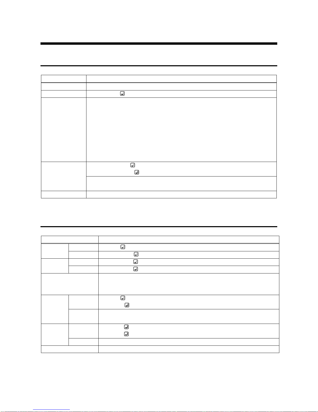
3.3 Detailed description
3.3.1 Error status
@ERR
Error status
Description
Response in case the command is not executed.
Response
@ERR, error
Parameter
error:Error status
1 = Erroneous parameter format or value
2 = Undefined command or wrong format
3 = The command cannot be used. Sequence switching mode is being operated.
4 = Not used.
5 = Not used.
6 = Not used.
7 = Not used.
8 = Loading EDID from the sink device failed.
Getting example
Command @AAA
Response @ERR,2
@AAA is sent.
Command format error.
Remarks
-
3.3.2 Selecting input channel
@GSW / @SSW
Input channel switching
Getting
Command
@GSW
Response
@GSW, input
Setting
Command
@SSW, input
Response
@SSW, input
Parameter
Input: Input channel
0 = OFF, 1 = IN1 to 4 = IN4
[Default] OFF
Getting
example
Command
Response
@GSW
@GSW,2
Description
Getting the input channel that is assigned to OUT.
IN2
Setting
example
Command
Response
@SSW,1
@SSW,1
Description
Setting OUT’s input channel to IN1.
Remarks
-
Page 15
IMP-400UHD Command Guide
15
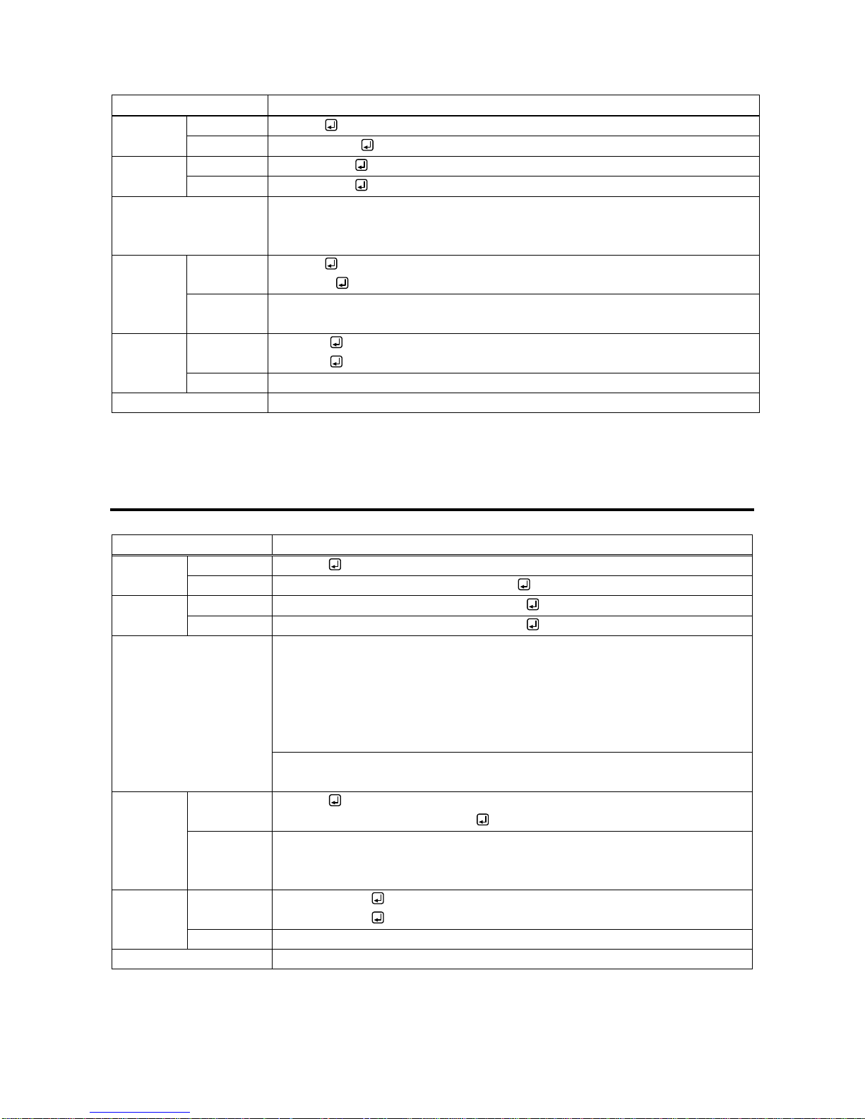
@GCP / @IOS
Input channel switching (For the previous model)
Getting
Command
@GCP
Response
@GCP, input
Setting
Command
@IOS, input
Response
@IOS, input
Parameter
input: Input channel
0 = OFF, 1 = IN1 to 4 = IN4
[Default] OFF
Getting
example
Command
Response
@GCP
@GCP,2
Description
Getting the input channel that is assigned to OUT.
IN2
Setting
example
Command
Response
@IOS,1
@IOS,1
Description
Setting OUT’s input channel to IN1.
Remarks
-
3.3.3 Input setting
@GDT / @SDT
No-signal-input monitoring
Getting
Command
@GDT
Response
@GDT, time_1, time_2, time_3, time_4
Setting
Command
@SDT, ch_1, time_1 (, ch_2, time_2・・・)
Response
@SDT, ch_1, time_1 (, ch_2, time_2・・・)
Parameter
time_1-4: No-signal-input monitoring
0 = OFF, 2000 = 2 sec. to 15000 = 15 sec.
[Default] 10000 = 10 sec.
Set the value by 100 ms. If you set a value other than 0 for the lower 2 digits,
these values will be rounded down.
(For example, if you set it to 2955, the monitoring time is set to 2900 ms.)
ch_1-4: Input channel
0 = All inputs, 1 = IN1 to 4 = IN4
Getting
example
Command
Response
@GDT
@GDT,6000,10000,10000,4000
Description
Getting the set monitoring time.
IN1: 6000 ms. (6 sec.), IN2 and IN3: 10000 ms. (10 sec.), IN4: 4000 ms. (4
sec.)
Setting
example
Command
Response
@SDT,3,6000
@SDT,3,6000
Description
Setting the monitoring time of IN3 to 6000 ms. (6 sec.).
Remarks
-
Page 16
IMP-400UHD Command Guide
16
@GHE / @SHE
HDCP input enabled/disabled
Getting
Command
@GHE
Response
@GHE, hdcp_1, hdcp_2, hdcp_3, hdcp_4
Setting
Command
@SHE, ch_1, hdcp_1 (, ch_2, hdcp_2・・・)
Response
@SHE, ch_1, hdcp_1 (, ch_2, hdcp_2・・・)
Parameter
hdcp_1-4: HDCP input enabled/disabled
0 = DISABLE, 1 = HDCP 1.4, 2 = HDCP 2.2
[Default] HDCP 2.2
ch_1-4: Input channel
0 = All inputs, 1 = IN1 to 4 = IN4
Getting
example
Command
Response
@GHE
@GHE,2,2,0,2
Description
Getting HDCP input enabled/disabled.
IN3: disables HDCP input, other input channels: enables HDCP 2.2 input
Setting
example
Command
Response
@SHE,1,0
@SHE,1,0
Description
Setting IN1 HDCP input to disabled.
Remarks
-
3.3.4 Switching setting
@GAU / @SAU
Priority of input channel automatic switching (OFF to ON)
Getting
Command
@GAU
Response
@GAU, in1_priority, in2_priority, in3_priority, in4_priority
Setting
Command
@SAU, in1_priority, in2_priority・・・, in4_priority
Response
@SAU, in1_priority, in2_priority・・・, in4_priority
Parameter
in1_priority - in4_priority: Priority
0 = OFF, 1 = Priority (high) to 4 = Priority (low)
[Default] OFF
Getting
example
Command
Response
@GAU
@GAU,1,2,3,4
Description
Getting the set priority (OFF to ON).
IN1>IN2>IN3>IN4
Setting
example
Command
Response
@SAU,4,3,2,1
@SAU,4,3,2,1
Description
Setting the priority to IN4>IN3>IN2>IN1.
Remarks
-
Page 17
IMP-400UHD Command Guide
17
@GOF / @SOF
Priority of input channel automatic switching (ON to OFF)
Getting
Command
@GOF
Response
@GOF, in1_priority, in2_priority, in3_priority, in4_priority
Setting
Command
@SOF, in1_priority, in2_priority・・・, in4_priority
Response
@SOF, in1_priority, in2_priority・・・, in4_priority
Parameter
in1_priority - in4_priority: Priority
0 = OFF, 1 = Priority (high) to 4 = Priority (low)
[Default] OFF
Getting
example
Command
Response
@GOF
@GOF,1,2,3,4
Description
Getting the set priority (ON to OFF).
IN1>IN2>IN3>IN4
Setting
example
Command
Response
@SOF,4,3,2,1
@SOF,4,3,2,1
Description
Setting the priority to IN4>IN3>IN2>IN1.
Remarks
-
@GMT / @SMT
Masking time after automatic switching of input channel
Getting
Command
@GMT
Response
@GMT, time
Setting
Command
@SMT, time
Response
@SMT, time
Parameter
time: Masking time
0 = 0 to 999999 = 999.999 sec.
[Default] 0 sec.
Getting
example
Command
Response
@GMT
@GMT,2000
Description
Getting the set masking time after automatic switching of input channel.
Automatic switching cannot be executed for 2000 ms. (2 sec.).
Setting
example
Command
Response
@SMT,2000
@SMT,2000
Description
Setting the masking time to 2000 ms. (2 sec.)
Remarks
-
Page 18
IMP-400UHD Command Guide
18
@GST / @SST
Sequence switching mode
Getting
Command
@GST
Response
@GST, mode
Setting
Command
@SST, mode
Response
@SST, mode
Parameter
mode: Sequence switching mode
0 = OFF, 1 = ON
[Default] OFF
Getting
example
Command
Response
@GST
@GST,0
Description
Getting the set sequence switching mode.
OFF
Setting
example
Command
Response
@SST,1
@SST,1
Description
Setting the sequence switching mode to ON.
Remarks
-
@GSQ / @SSQ
Target channel for sequence switching mode
Getting
Command
@GSQ
Response
@GSQ, select_1, select_2, select_3, select_4
Setting
Command
@SSQ, ch_1, select_1 (, ch_2, select_2・・・)
Response
@SSQ, ch_1, select_1 (, ch_2, select_2・・・)
Parameter
select_1-4: Setting whether the channel is switched or not.
0 = Not switched, 1 = Switched [Default] 1 (Switched)
ch_1-4: Input channel
0 = All inputs, 1 = IN1 to 4 = IN4
Getting
example
Command
Response
@GSQ
@GSQ,1,1,1,0
Description
Getting the set mode status.
IN1 to IN3 will be switched.
Setting
example
Command
Response
@SSQ,1,0
@SSQ,1,0
Description
IN1 will not be switched.
Command
Response
@SSQ,0,0
@ERR,1
Description
Error, because all input channels are set to OFF.
Remarks
-
Page 19
IMP-400UHD Command Guide
19
@GIT / @SIT
Switching interval for sequence switching mode
Getting
Command
@GIT
Response
@GIT, time
Setting
Command
@SIT, time
Response
@SIT, time
Parameter
time: Switching interval
10000 = 10 to 30000 = 30 sec.
[Default] 10 sec.
Getting
example
Command
Response
@GIT
@GIT,20000
Description
Getting set switching interval.
20 sec.
Setting
example
Command
Response
@SIT,15000
@SIT,15000
Description
Setting the switching interval to 15 sec.
Remarks
-
@GSD / @SSD
Input detection
Getting
Command
@GSD
Response
@GSD, detect
Setting
Command
@SSD, detect
Response
@SSD, detect
Parameter
detect: Channels that is detected will be switched in sequence switching mode.
0 = All input channels will be switched.
1 = Only channels that is detected will be switched.
[Default] Only channels that is detected will be switched.
Getting
example
Command
Response
@GSD
@GSD,0
Description
Getting the setting.
All input channels will be switched in sequence switching mode..
Setting
example
Command
Response
@SSD,1
@SSD,1
Description
Only channels that is detected will be switched in sequence switching mode..
Remarks
-
Page 20
IMP-400UHD Command Guide
20
@GSC / @SSC
Starting channel of sequence switching mode
Getting
Command
@GSC
Response
@GSC, select
Setting
Command
@SSC, select
Response
@SSC, select
Parameter
select: Starting channel
0 = Starts from the current input channel
1 = Starts from the lowest target channel
[Default] 0 (Starts from the current input channel)
Getting
example
Command
Response
@GSC
@GSC,1
Description
Getting the starting channel.
Starts from the lowest target channel
Setting
example
Command
Response
@SSC,0
@SSC,0
Description
Setting the mode to start from the current input channel
Remarks
-
Page 21
IMP-400UHD Command Guide
21
3.3.5 Output settings
@GDM / @SDM
Output mode
Getting
Command
@GDM
Response
@GDM, mode
Setting
Command
@SDM, mode
Response
@SDM, mode
Parameter
mode: Output mode
0 = AUTO, 1 = DVI, 2 = RGB, 3 = YCbCr4:2:0,
4 = YCbCr4:2:2, 5 = YCbCr4:4:4
[Default] 0 (AUTO)
Getting
example
Command
Response
@GDM
@GDM,3
Description
Getting the set output mode.
YCbCr4:2:0
Setting
example
Command
Response
@SDM,3
@SDM,3
Description
Setting the output mode to “YCbCr4:2:0”.
Remarks
-
@GCO / @SCO
Sink device EDID check
Getting
Command
@GCO
Response
@GCO, mode
Setting
Command
@SCO, mode
Response
@SCO, mode
Parameter
mode: Sink device EDID check
0 = In case of EDID load error, the sink device is treated as a DVI device.
1 = In case of EDID load error, the sink device is treated as a HDMI (without
SCDC) device.
2 = Always the sink device is treated as a HDMI (without SCDC) device.
3 = In case of EDID load error, the sink device is treated as a HDMI (with
SCDC) device.
4 = Always the sink device is treated as a HDMI (with SCDC) device.
[Default] 0 (In case of EDID load error, the sink device is treated as a DVI
device.)
Getting
example
Command
Response
@GCO
@GCO,3
Description
Getting the set mode.
In case of EDID load error, the sink device is treated as a HDMI (with SCDC)
device.
Setting
example
Command
Response
@SCO,0
@SCO,0
Description
Setting this menu to the sink device is treated as a DVI device in case of EDID
load error.
Remarks
-
Page 22
IMP-400UHD Command Guide
22
@HAU
HDCP re-encryption
Setting
Command
@HAU
Response
@HAU
Parameter
NA
Setting
example
Command
Response
@HAU
@HAU
Description
Setting OUT to re-encrypt HDCP.
Remarks
-
3.3.6 Audio setting
@GAM / @SAM
Audio output mute
Getting
Command
@GAM
Response
@GAM, mute
Setting
Command
@SAM, mute
Response
@SAM, mute
Parameter
mute: Audio output mute
0 = OFF, 1 = ON
[Default] OFF
Getting
example
Command
Response
@GAM
@GAM,0
Description
Getting the set value of audio output mute.
OFF
Setting
example
Command
Response
@SAM,1
@SAM,1
Description
Muting digital / analog audio output.
Remarks
-
Page 23
IMP-400UHD Command Guide
23
3.3.7 Contact input
@GFP / @SFP
Chattering reduction time of contact input
Getting
Command
@GFP
Response
@GFP, time
Setting
Command
@SFP, time
Response
@SFP, time
Parameter
time: Chattering reduction time
0 = 0 ms to 300 = 300 ms
[Default] 30 ms
Getting
example
Command
Response
@GFP
@GFP,10
Description
Getting the set chattering reduction time.
10 ms。
Setting
example
Command
Response
@SFP,10
@SFP,10
Description
Setting the chattering reduction time to 10 ms.
Remarks
-
Page 24
IMP-400UHD Command Guide
24
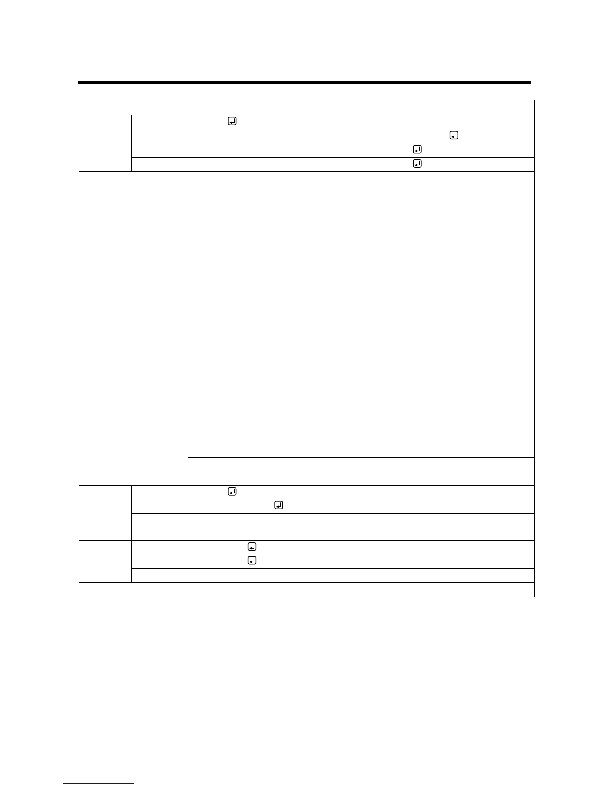
3.3.8 EDID
@GVF / @SVF
EDID resolution
Getting
Command
@GVF
Response
@GVF resolution_1, resolution_2, resolution_3, resolution_4
Setting
Command
@SVF, ch_1, resolution_1 (, ch_2, resolution_2・・・)
Response
@SVF, ch_1, resolution_1 (, ch_2, resolution_2・・・)
Parameter
resolution_1-4: EDID resolution
0 = EXTERNAL, 1 = Copied EDID,
2 = SVGA (800x600), 3 = XGA (1024x768),
4 = VESA720 (1280x720), 5 = 720p,
6 = WXGA (1280x768), 7 = WXGA (1280x800),
8 = Quad-VGA (1280x960), 9 = SXGA (1280x1024),
10 = WXGA (1360x768), 11 = WXGA (1366x768),
12 = SXGA+ (1400x1050), 13 = WXGA+ (1440x900),
14 = WXGA++ (1600x900), 15 = UXGA (1600x1200),
16 = WSXGA+ (1680x1050), 17 = 1080i
18 = 1080p@24 / 25 / 30 (1920x1080) 19 = VESA1080 (1920x1080),
20 = 1080p@50 / 59.94 / 60 (1920x1080) 21 = WUXGA (1920x1200),
22 = QWXGA (2048x1152), 23 = WQHD (2560x1440),
24 = WQXGA (2560x1600),
41 = 2160p@24 / 25 / 30 (3840x2160),
42 = 4096x2160@24 / 25 / 30,
43 = 2160p@50 / 59.94 / 60 - 4:2:0 (3840x2160),
44 = 4096x2160@50 / 59.94 / 60 - 4:2:0,
45 = 2160p@50 / 59.94 / 60 - 4:4:4 (3840x2160)
46 = 4096x2160@50 / 59.94 / 60 - 4:4:4
[Default]2160p@50 / 59.94 / 60 - 4:4:4 (3840x2160)
ch_1-4: Input channel
0 = All inputs, 1 = IN1 to 4 = IN4
Getting
example
Command
Response
@GVF
@GVF,45,45,45,9
Description
Getting the set EDID resolution.
IN4: SXGA(1280x1024), other inputs: 2160p@50 / 59.94 / 60 - 4:4:4 (3840x2160)
Setting
example
Command
Response
@SVF,0,15
@SVF,0,15
Description
Setting EDID of all input channels to UXGA (1600x1200).
Remarks
-
Page 25
IMP-400UHD Command Guide
25
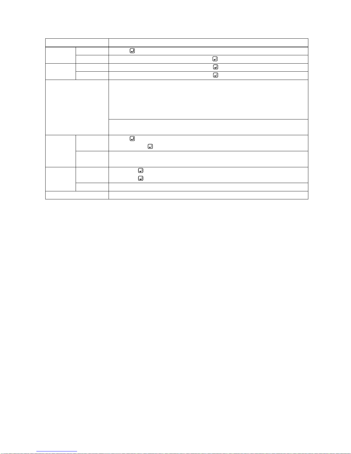
@GDI / @SDI
Deep Color input
Getting
Command
@GDI
Response
@GDI, color_1, color_2, color_3, color_4
Setting
Command
@SDI, ch_1, color_1 (, ch_2, color_2・・・)
Response
@SDI, ch_1, color_1 (, ch_2, color_2・・・)
Parameter
color_1-4: Color depth
0 = 24 bit / pixel (8 bit / component)
1 = 30 bit / pixel (10 bit / component)
2 = 36 bit / pixel (12 bit / component)
[Default] 24 bit / pixel (8 bit / component)
ch_1-4: Input channel
0 = All inputs, 1 = IN1 to 4 = IN4
Getting
example
Command
Response
@GDI
@GDI,1,1,1,0
Description
Getting the set color depth.
IN4: 24 bit / pixel (8 bit / component); others: 30 bit / pixel (10 bit / component)
Setting
example
Command
Response
@SDI,4,0
@SDI,4,0
Description
Setting IN4 color depth to 24 bit / pixel (8 bit / component).
Remarks
-
Page 26
IMP-400UHD Command Guide
26
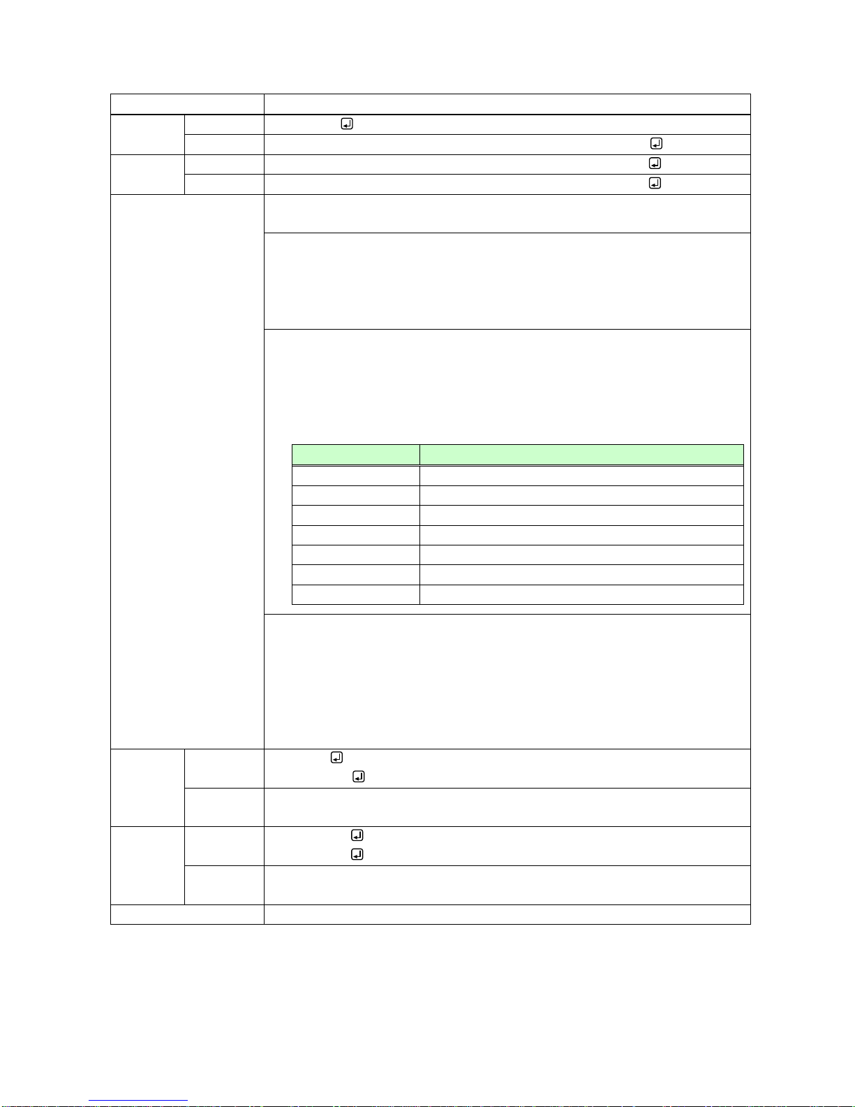
@GAF / @SAF
Audio format
Getting
Command
@GAF, ch
Response
@GAF, ch, format_1, frequency_1 (, format_2, frequency_2・・・)
Setting
Command
@SAF, ch, format_1, frequency_1 (, format_2, frequency_2・・・)
Response
@SAF, ch, format_1, frequency_1 (, format_2, frequency_2・・・)
Parameter
ch: Input channel
0 = All inputs (for setting only), 1 = IN1 to 4 = IN4
format_1-4: Audio format
0 = PCM, 1 = Dolby Digital, 2 = AAC,
3 = Dolby Digital+, 4 = DTS, 5 = DTS-HD,
6 = Dolby TrueHD
[Default] only PCM can be output
frequency_1-4: Maximum sampling frequency
0 = Cannot be output, 1 = 32 kHz, 2 = 44.1 kHz, 3 = 48 kHz,
4 = 88.2 kHz, 5 = 96 kHz, 6 = 176.4 kHz, 7 = 192 kHz
[Default] PCM: 48 kHz; others: 0 (Cannot be output)
Maximum settable sampling frequency depends on the audio format.
Audio format
Maximum sampling frequency (kHz)
PCM
32 / 44.1 / 48 / 88.2 / 96 / 176.4 / 192
Dolby Digital
Cannot be output / 32 / 44.1 / 48
AAC
Cannot be output / 32 / 44.1 / 48 / 88.2 / 96
Dolby Digital+
Cannot be output / 32 / 44.1 / 48
DTS
Cannot be output / 32 / 44.1 / 48 / 96
DTS-HD
Cannot be output / 44.1 / 48 / 88.2 / 96 / 176.4 / 192
Dolby TrueHD
Cannot be output / 44.1 / 48 / 88.2 / 96 / 176.4 / 192
Getting commands: the set audio formats and maximum sampling frequency is
returned.
Setting commands: send the desired audio formats and the maximum sampling
frequencies.
Audio formats that are not sent are set to “0” (Cannot be output).
PCM is always enabled, you can skip this menu unless you need to change the
sampling frequency.
Getting
example
Command
Response
@GAF,1
@GAF,1,0,7
Description
Getting the set audio formats for IN1.
PCM, up to 192 kHz
Setting
example
Command
Response
@SAF,2,4,3
@SAF,2,4,3
Description
Setting IN2 to output audio PCM and DTS 48 kHz.
(PCM’s sampling frequency is not changed).
Remarks
-
Page 27
IMP-400UHD Command Guide
27
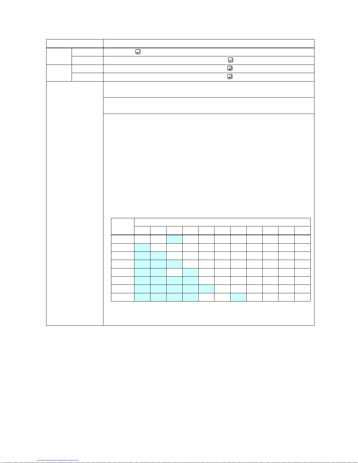
@GSP / @SSP
The number of speakers
Getting
Command
@GSP, ch
Response
@GSP, ch, number, speaker_1 (, speaker_2・・・)
Setting
Command
@SSP, ch, number (, speaker_1, speaker_2・・・)
Response
@SSP, ch, number (, speaker_1, speaker_2・・・)
Parameter
ch: Input channel
0 = All inputs (for setting only), 1 = IN1 to 4 = IN4
number: The number of speakers
1 to 8 [Default] 2
speaker_1-8: Speaker configuration
0 = Front Left / Right [Default], 1 = Low Frequency Effect,
2 = Front Center, 3 = Rear Left / Right,
4 = Rear Center, 5 = Front Left / Right Center,
6 = Rear Left / Right Center, 7 = Front Left / Right Wide,
8 = Front Left / Right High, 9 = Top Center,
10 = Front Center High
Getting commands: the number of speakers and which speakers will be used is
returned.
Setting commands: if you do not specify the speaker configuration, the following
configuration will be applied depending on the set number of speakers.
number
speaker
0 1 2 3 4 5 6 7 8 9 10
1
OFF
OFF
ON
OFF
OFF
OFF
OFF
OFF
OFF
OFF
OFF
2
ON
OFF
OFF
OFF
OFF
OFF
OFF
OFF
OFF
OFF
OFF 3 ON
ON
OFF
OFF
OFF
OFF
OFF
OFF
OFF
OFF
OFF
4
ON
ON
ON
OFF
OFF
OFF
OFF
OFF
OFF
OFF
OFF 5 ON
ON
OFF
ON
OFF
OFF
OFF
OFF
OFF
OFF
OFF
6
ON
ON
ON
ON
OFF
OFF
OFF
OFF
OFF
OFF
OFF
7
ON
ON
ON
ON
ON
OFF
OFF
OFF
OFF
OFF
OFF 8 ON
ON
ON
ON
OFF
OFF
ON
OFF
OFF
OFF
OFF
For speaker configurations: the number and total number of speakers (speaker_1-8)
do not match, the number is set automatically based on the setting of speaker
configuration. In case the number exceeds the settable range, an error is returned.
Page 28
IMP-400UHD Command Guide
28
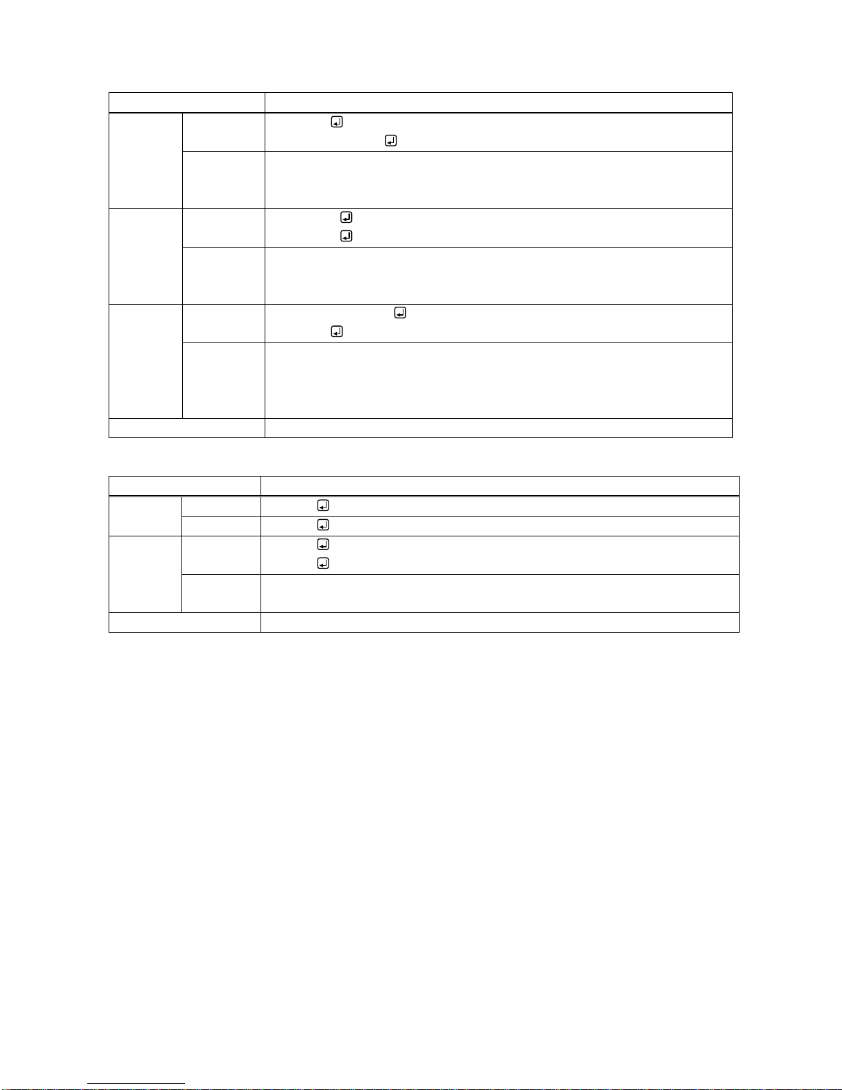
@GSP / @SSP
The number of speakers (cont’d)
Getting
example
Command
Response
@GSP,1
@GSP,1,6,0,1,2,3
Description
Getting the IN1 speaker configuration.
Six speakers (Front Left / Right, Low Frequency Effect, Front Center, Rear Left /
Right) are used.
Setting
example
Command
Response
@SSP,2,8
@SSP,2,8
Description
Setting IN2 speaker configuration to Front Left / Right, Low Frequency Effect,
Front Center, Rear Left / Right, Rear Left / Right Center (eight speakers).
Completed normally.
Setting
example
Command
Response
@SSP,3,8,0,3,5,6,7
@ERR,1
Description
Setting IN3 speaker configuration to Front Left / Right, Rear Left / Right, Front
Left / Right Center, Rear Left / Right Center, Front Left / Right Wide.
The number of speakers is 10 which exceeds the settable value, and it causes
the error.
Remarks
-
@RME
EDID copy
Setting
Command
@RME
Response
@RME
Setting
example
Command
Response
@RME
@RME
Description
Loading EDID data of the sink device connected to the HDMI output connector
and saving it in the IMP-400UHD.
Remarks
-
Page 29
IMP-400UHD Command Guide
29
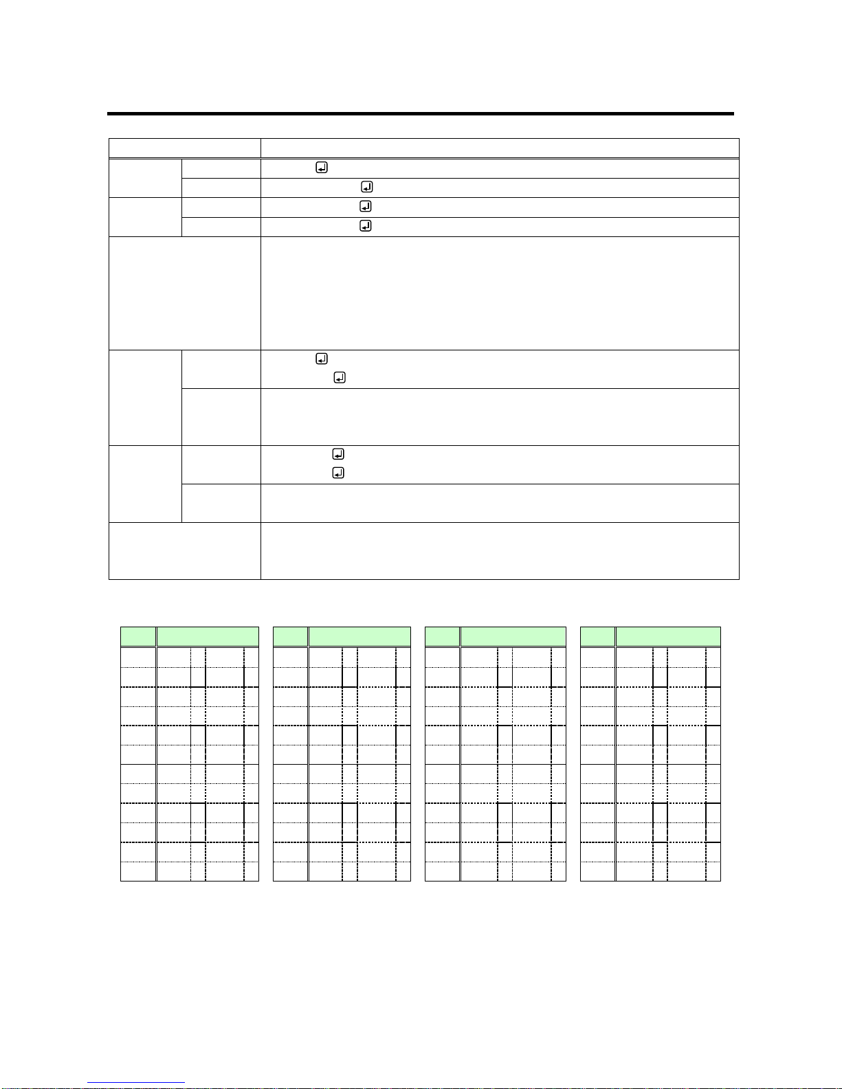
3.3.9 RS-232C communication
@GCT / @SCT
RS-232C communication
Getting
Command
@GCT
Response
@GCT, setting
Setting
Command
@SCT, setting
Response
@SCT, setting
Parameter
setting: Communication setting
・Baud rate (4800, 9600, 19200, 38400 [bps] [Default] 9600)
・Data length (8, 7 [bit] [Default] 8)
・Parity check (NONE, EVEN, ODD [Default]: NONE)
・Stop bit (1, 2 [bit] [Default] 1)
For setting values, see the table below.
Getting
example
Command
Response
@GCT
@GCT,24
Description
Getting communication settings of RS-232Cs.
All baud rates = 19200 [bps], data bit length = 8 [bit], parity check = None, stop bit
= 1 [bit]
Setting
example
Command
Response
@SCT,24
@SCT,24
Description
Baud rate =19200 [bps], data bit length = 8 [bit], parity check = NONE, stop bit = 1
[bit].
Remarks
If IP address or RS-232C communication setting is changed, the communication
may be disabled. Change the environmental settings of communication based on
the IMP-400UHD settings.
[Table 3.1] Parameter for RS-232C communication settings
Value
Communication
Value
Communication
Value
Communication
Value
Communication
0
4800 8 NONE
1 12
9600 8 NONE
1 24
19200
8
NONE
1 36
38400
8
NONE
1
1
4800 8 NONE
2 13
9600 8 NONE
2 25
19200
8
NONE
2 37
38400
8
NONE 2 2
4800 8 ODD 1
14
9600 8 ODD 1
26
19200
8
ODD 1
38
38400
8
ODD
1
3
4800 8 ODD 2
15
9600 8 ODD 2
27
19200
8
ODD 2
39
38400
8
ODD
2
4
4800 8 EVEN
1 16
9600 8 EVEN
1 28
19200
8
EVEN
1 40
38400
8
EVEN 1 5
4800 8 EVEN
2 17
9600 8 EVEN
2 29
19200
8
EVEN
2 41
38400
8
EVEN
2
6
4800 7 NONE
1 18
9600 7 NONE
1 30
19200
7
NONE
1 42
38400
7
NONE
1
7
4800 7 NONE
2 19
9600 7 NONE
2 31
19200
7
NONE
2 43
38400
7
NONE 2 8
4800 7 ODD 1
20
9600 7 ODD 1
32
19200
7
ODD 1
44
38400
7
ODD 1 9
4800 7 ODD 2
21
9600 7 ODD 2
33
19200
7
NONE
2 45
38400
7
EVEN
2
10
4800 7 EVEN
1 22
9600 7 EVEN
1 34
19200
7
EVEN
1 46
38400
7
EVEN
1
11
4800 7 EVEN
2 23
9600 7 EVEN
2 35
19200
7
EVEN
2 47
38400
7
EVEN
2
Page 30
IMP-400UHD Command Guide
30
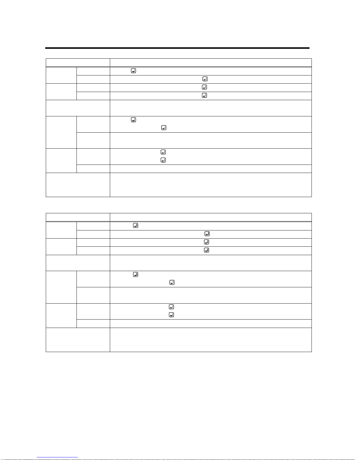
3.3.10 LAN communication
@GIP / @SIP
IP address
Getting
Command
@GIP
Response
@GIP, unit_1, unit_2, unit_3, unit_4
Setting
Command
@SIP, unit_1, unit_2, unit_3, unit_4
Response
@SIP, unit_1, unit_2, unit_3, unit_4
Parameter
unit_1: Upper bit of the IP address to unit_4: lower bit of the IP address
0 to 255 = 8 bit (Decimal notation) [Default] 192.168.1.199
Getting
example
Command
Response
@GIP
@GIP,192,168,3,2
Description
Getting the set IP address of the IMP-400UHD.
IP address:192.168.3.2。
Setting
example
Command
Response
@SIP,192,168,3,2
@SIP,192,168,3,2
Description
Setting IP address to 192.168.3.2.
Remarks
If IP address or RS-232C communication setting is changed, the communication
may be disabled. Change the environmental settings of communication based on
the IMP-400UHD settings.
@GSB / @SSB
Subnet mask
Getting
Command
@GSB
Response
@GSB, unit_1, unit_2, unit_3, unit_4
Setting
Command
@SSB, unit_1, unit_2, unit_3, unit_4
Response
@SSB, unit_1, unit_2, unit_3, unit_4
Parameter
unit_1: Upper bit of the subnet mask to unit_4: lower bit of the subnet mask
0 to 255 = 8 bit (Decimal notation) [Default] 255.255.255.0
Getting
example
Command
Response
@GSB
@GSB,255,255,192,0
Description
Getting the set subnet mask of the IMP-400UHD.
Subnet mask: 255.255.192.0 ( = 18 bit)
Setting
example
Command
Response
@SSB,255,255,192,0
@SSB,255,255,192,0
Description
Setting subnet mask to 255.255.192.0 ( = 18 bit) .
Remarks
If IP address or RS-232C communication setting is changed, the communication
may be disabled. Change the environmental settings of communication based on
the IMP-400UHD settings.
Page 31
IMP-400UHD Command Guide
31
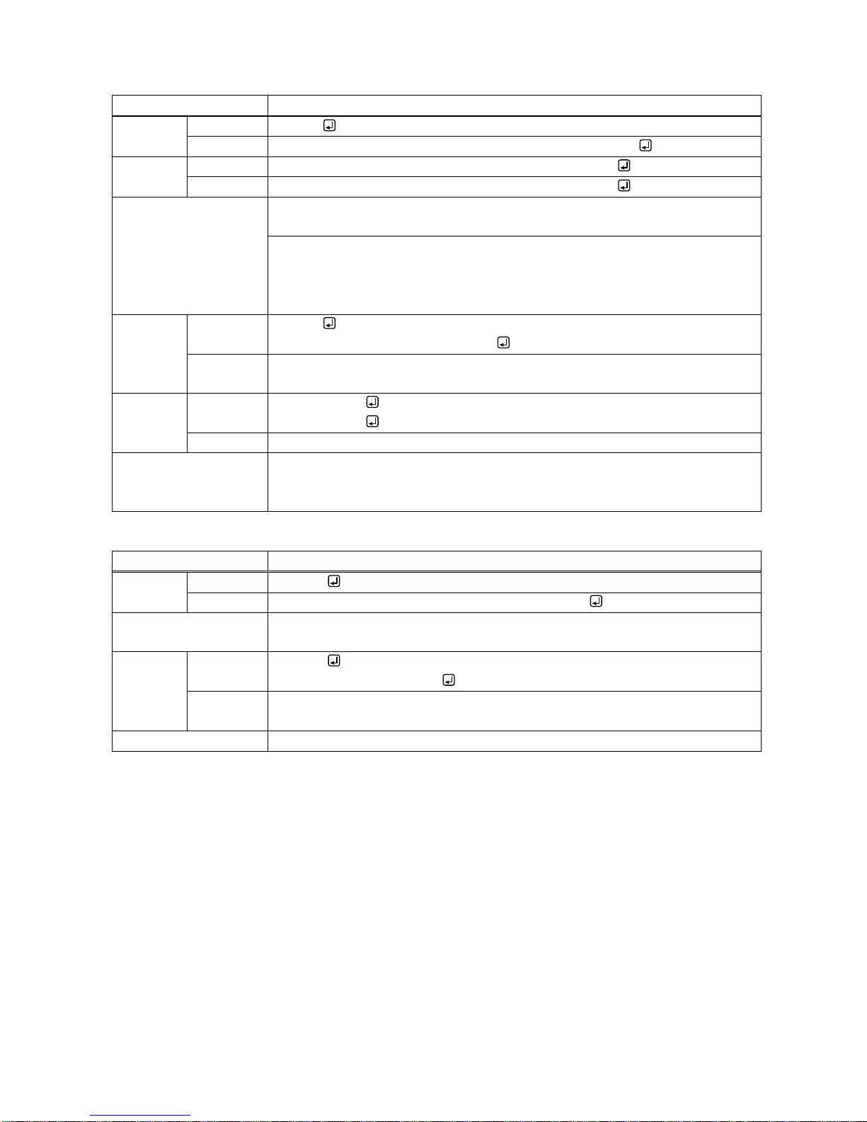
@GLP / @SLP
TCP port number
Getting
Command
@GLP
Response
@GLP, port_1, port_2, port_3, port_4, port_5, port_6, port_7
Setting
Command
@SLP, connection_1, port_1 (, connection_2, port_2・・・)
Response
@SLP, connection_1, port_1 (, connection_2, port_2・・・)
Parameter
connection_1-7: Connection number
0 = All connections, 1 = Connection1 to 7 = Connection 7
port_1-7: TCP port number
23, 1100, 6000 to 6999
[Default]
Connections 1 to 4 = 1100; Connections 5 to 7 = 23
Getting
example
Command
Response
@GLP
@GLP,1100,1100,1100,23,23,23,23
Description
Getting the set TCP port number.
Connections 1 to 3: 1100; Connections 4 to 7: 23
Setting
example
Command
Response
@SLP,7,6000
@SLP,7,6000
Description
Setting port number of connection 7 to “6000”.
Remarks
If IP address or RS-232C communication setting is changed, the communication
may be disabled. Change the environmental settings of communication based on
the IMP-400UHD settings.
@GMC
MAC address
Getting
Command
@GMC
Response
@GMC, unit_1, unit_2, unit_3, unit_4, unit_5, unit_6
Parameter
unit_1: Upper bit of the MAC address to unit_6: lower bit of the MAC address
00 to FF = 8 bit (in hexadecimal)
Getting
example
Command
Response
@GMC
@GMC,00,08,E5,5C,00,00
Description
Getting the set MAC address.
MAC address: 00-08-E5-5C-00-00。
Remarks
-
Page 32
IMP-400UHD Command Guide
32
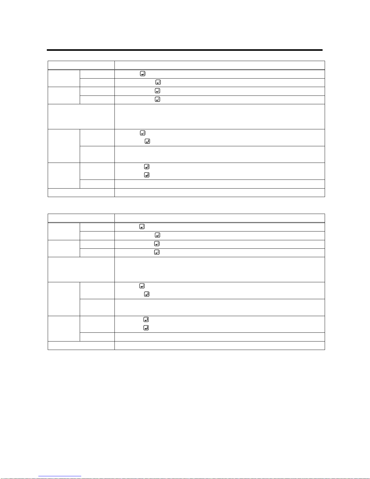
3.3.11 Startup settings
@GMU / @SMU
Startup input channel
Getting
Command
@GMU
Response
@GMU, state
Setting
Command
@SMU, state
Response
@SMU, state
Parameter
state: Startup input channel
1 = IN1 to 4 = IN4, 5 = Channel OFF, 6 = Last channel
[Default] Last channel
Getting
example
Command
Response
@GMU
@GMU,3
Description
Getting the set input channel at startup.
IN3
Setting
example
Command
Response
@SMU,3
@SMU,3
Description
Setting the startup channel to IN3.
Remarks
-
@GSO / @SSO
Startup operation lock
Getting
Command
@GSO
Response
@GSO, state
Setting
Command
@SSO, state
Response
@SSO, state
Parameter
state: Setting the operation lock for startup
0 = AUTO, 1 = UNLOCK, 2 = LOCK
[Default] AUTO
Getting
example
Command
Response
@GSO
@GSO,1
Description
Getting the setting for startup.
UNLOCK
Setting
example
Command
Response
@SSO,1
@SSO,1
Description
Setting this menu to “1” (UNLOCK).
Remarks
-
Page 33
IMP-400UHD Command Guide
33
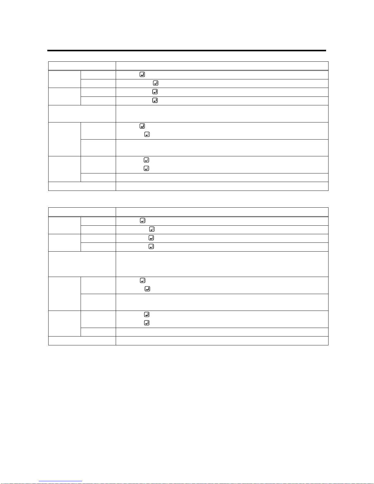
3.3.12 Other settings
@GLS / @SLS
Operation lock
Getting
Command
@GLS
Response
@GLS, lock
Setting
Command
@SLS, lock
Response
@SLS, lock
Parameter
lock: Operation lock
0 = Unlock [Default], 1 = Lock, 2 = Toggle
Getting
example
Command
Response
@GLS
@GLS,1
Description
Getting the operation lock status.
Locked
Setting
example
Command
Response
@SLS,1
@SLS,1
Description
Enabling operation lock.
Remarks
-
@GBZ / @SBZ
Buzzer
Getting
Command
@GBZ
Response
@GBZ, bz
Setting
Command
@SBZ, bz
Response
@SBZ, bz
Parameter
bz: Buzzer sound
0 = OFF, 1 = ON
[Default] ON
Getting
example
Command
Response
@GBZ
@GBZ,1
Description
Getting the buzzer status.
ON
Setting
example
Command
Response
@SBZ,1
@SBZ,1
Description
Enabling buzzer.
Remarks
-
Page 34
IMP-400UHD Command Guide
34
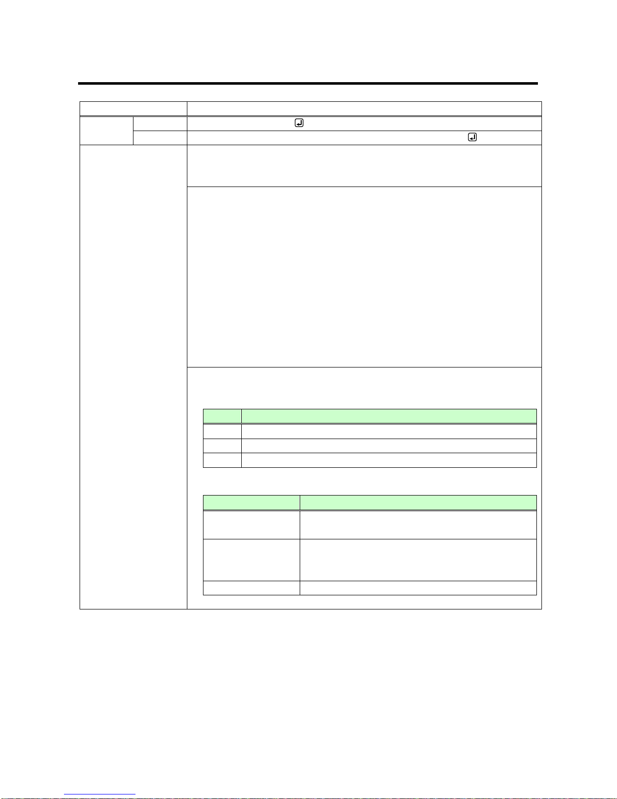
3.3.13 Displaying status
@GSS
Displaying input signal status / sink device status
Getting
Command
@GSS, channel, mode
Response
@GSS, channel, mode, status_1 (, status_2, status_3, status_4)
Parameter
channel: I/O channel
1 = IN (Selected input channel)
11 = OUT (Output channel)
mode: Target status
channel = For 1 (selected input channel)
0 = All of 1 to 4,
1 = Input signal type*1,
2 = Video input signal format*2,
3 = Audio input signal format*3,
4 = with/without HDCP*4
channel = For 11 (Output channel)
0 = All of 1 to 3,
1 = HDCP authentication status*5,
2 = Output signal type*6,
3 = Error code*7
status_1-4: Status
*1 One of the following values is returned.
Return
Input signal type
Hxx
HDMI signal is input. xx stands for color depth which is 24, 30 or 36.
D
DVI signal is input.
N
No signal is input.
*2 For format of video input signal
Return example
Format of video input signal
1080i 59.94Hz
SDTV/HDTV signal is input, which replies the format
type and vertical synchronous frequency.
800 x 600 60.00Hz
VESA signal is input, and [Horizontal resolution x
Vertical resolution] and vertical synchronous
frequency are returned.
NO SIGNAL
No video signal is input.
Page 35
IMP-400UHD Command Guide
35
@GSS
Displaying input signal status / sink device status (cont’d)
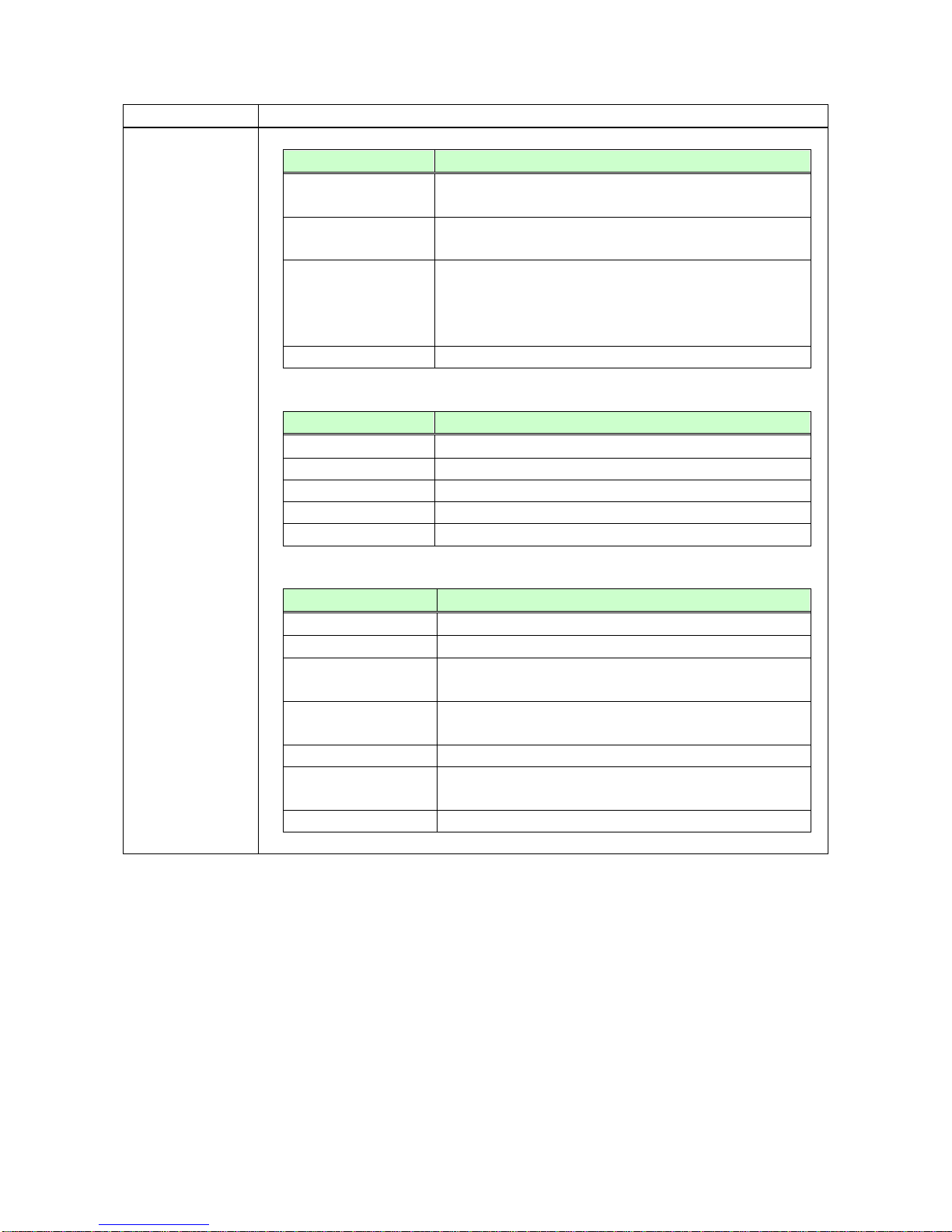
Parameter
*3 Format of audio input signal
Return example
Format of audio input signal
LINEAR PCM 48kHz
Linear PCM signal is input. Sampling frequency is
returned.
LINEAR PCM 48kHz
(MULTI CHANNEL)
Multi channel linear PCM signal is input. Sampling
frequency is returned.
COMPRESSED
AUDIO
Compressed audio signal (such as Dolby Digital and
DTS) is input (The IMP-400UHD does not recognize
detailed formats. “COMPRESSED AUDIO” is sent to all
compressed audio).
NO SIGNAL
No audio signal is input.
*4 With/without HDCP
Return example
Input HDCP status
HDCP 2.2 Type0
HDCP 2.2 stream type 0 signal is input.
HDCP 2.2 Type1
HDCP 2.2 stream type 1 signal is input.
HDCP 1.4
HDCP 1.4 signal is input.
HDCP OFF
Signal that is not protected by HDCP is input.
NO SIGNAL
No signal is input.
*5 HDCP authentication
Return example
HDCP authentication
HDCP2.2 SUPPORT
HDCP 2.2-compliant sink device is connected.
HDCP1.4 SUPPORT
HDCP 1.4-compliant sink device is connected.
HDCP NOT
SUPPORT
Non-HDCP-compliant sink device is connected or input
signal is without HDCP.
HDCP ERROR
HDCP-compliant sink device is connected, but the
authentication failed.
HDCP CHECK NOW
Sink device status is being checked.
MONITOR
DISCONNECT
No sink device is connected.
UNCONNECTED
HDCP 2.2-compliant sink device is connected.
Page 36
IMP-400UHD Command Guide
36
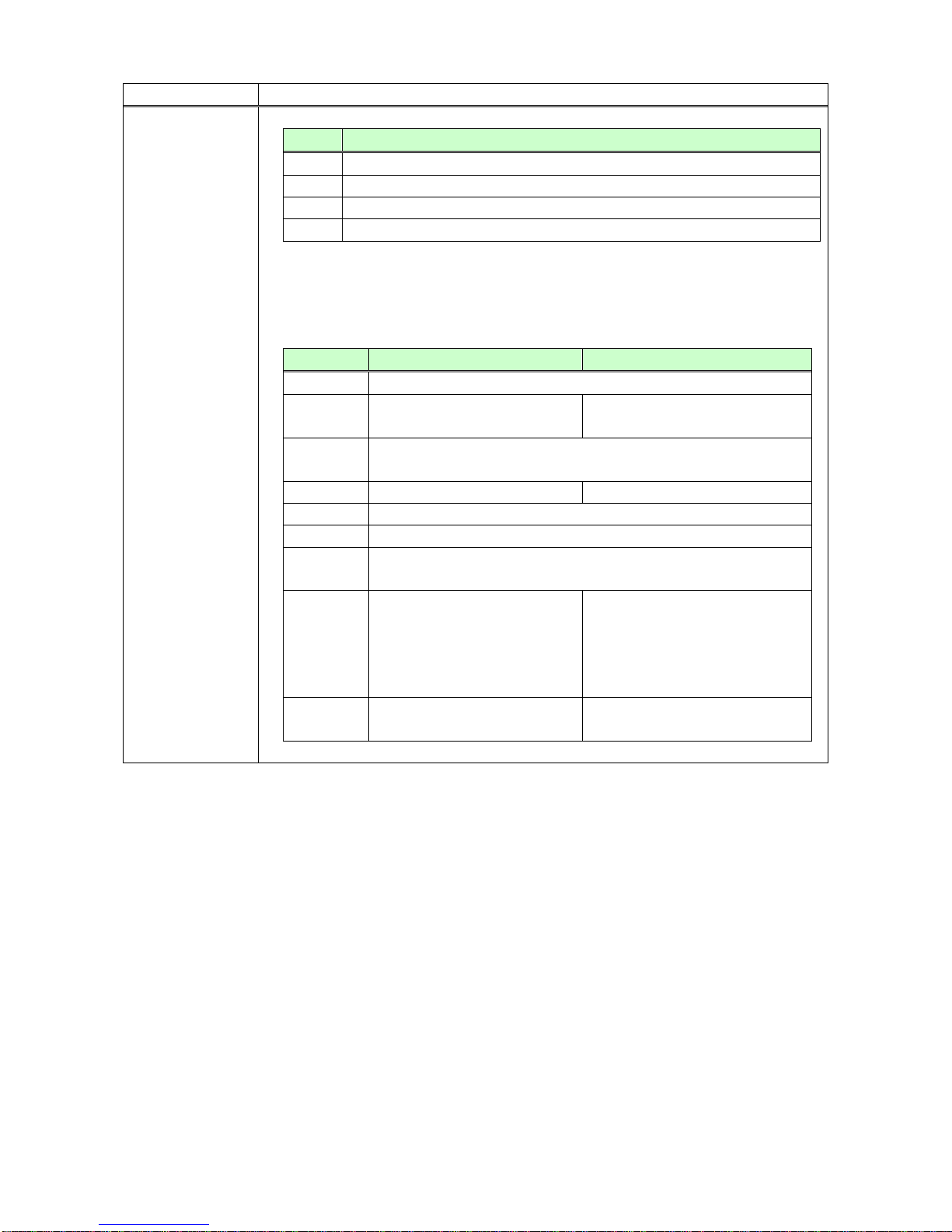
@GSS
Displaying input signal status / sink device status (cont’d)
Parameter
*6 Output signal type
Return
Output signal type
Hxx
HDMI signal is output. xx stands for the color depth, 24, 30, or 36.
D
DVI signal is output.
C
No video is output. HDCP is being authorized.
N
No sink device is connected.
*7 An error code is returned in the following order: video output to HDMI output
connector, audio output to HDMI output connector, audio output to AUDIO OUTPUT
connector.
Error code
Video output status
Audio output status
0
Video or audio is output correctly.
1
-
“@GAM / @SAMAudio output
mute” is set to “ON”.
2
DDC power is not input. (If no source device is connected, this
error code is displayed.)
3
No video signal is input.
No audio signal is input.
4
Video or audio output of the source device is muted.
5
Signal with HDCP is input but the sink device is HDCP incompliant
6
The source device does not output information (packets) required
for video or audio output.
7
Signal that is not supported by
the IMP-400UHD is input.
Since compressed audio is input,
audio cannot be output
(Compressed audio can be
output only to sink devices
supporting compressed audio).
9
-
Sink device that does not support
audio is connected.*8
Page 37
IMP-400UHD Command Guide
37
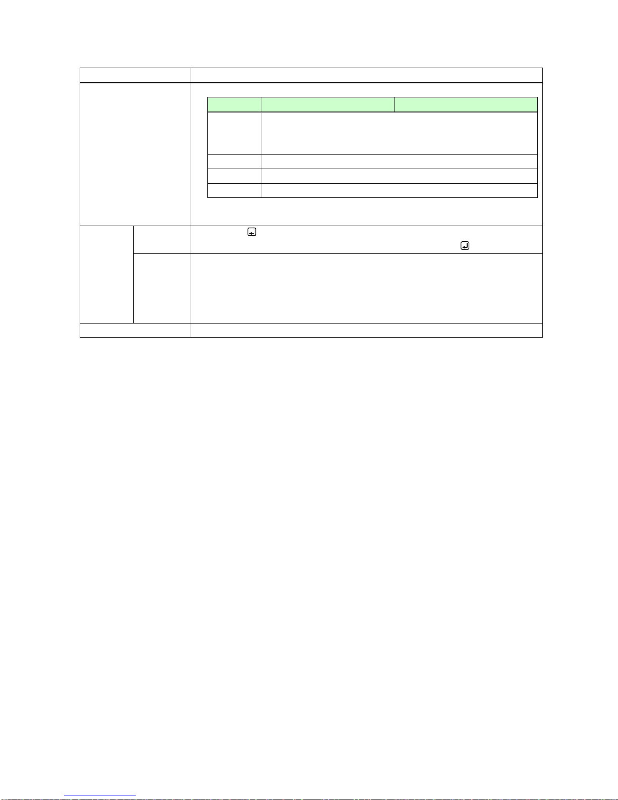
@GSS
Displaying input signal status / sink device status (cont’d)
Parameter
Error code
Video output status
Audio output status
A
Input channel is set to “OFF”
( @GSW / @SSWInput channel (P.14),
@GCPInput channel (P.15) )
B
No sink device is connected.
C
HDCP is being authenticated.
D
HDCP authentication failed.
*8 Status of the HDMI output connector
Getting
example
Command
Response
@GSS,1,0
@GSS,1,0,H30,1080P 60Hz,LINEAR PCM 48kHz, HDCP 1.4
Description
Getting all IN1 statuses.
・Input signal type: 30 bit / pixel (10 bit / component) signal
・Video input signal: 1080P 60Hz
・Audio input signal: LINEAR PCM 48kHz
・HDCP: HDCP 1.4
Remarks
-
Page 38
IMP-400UHD Command Guide
38
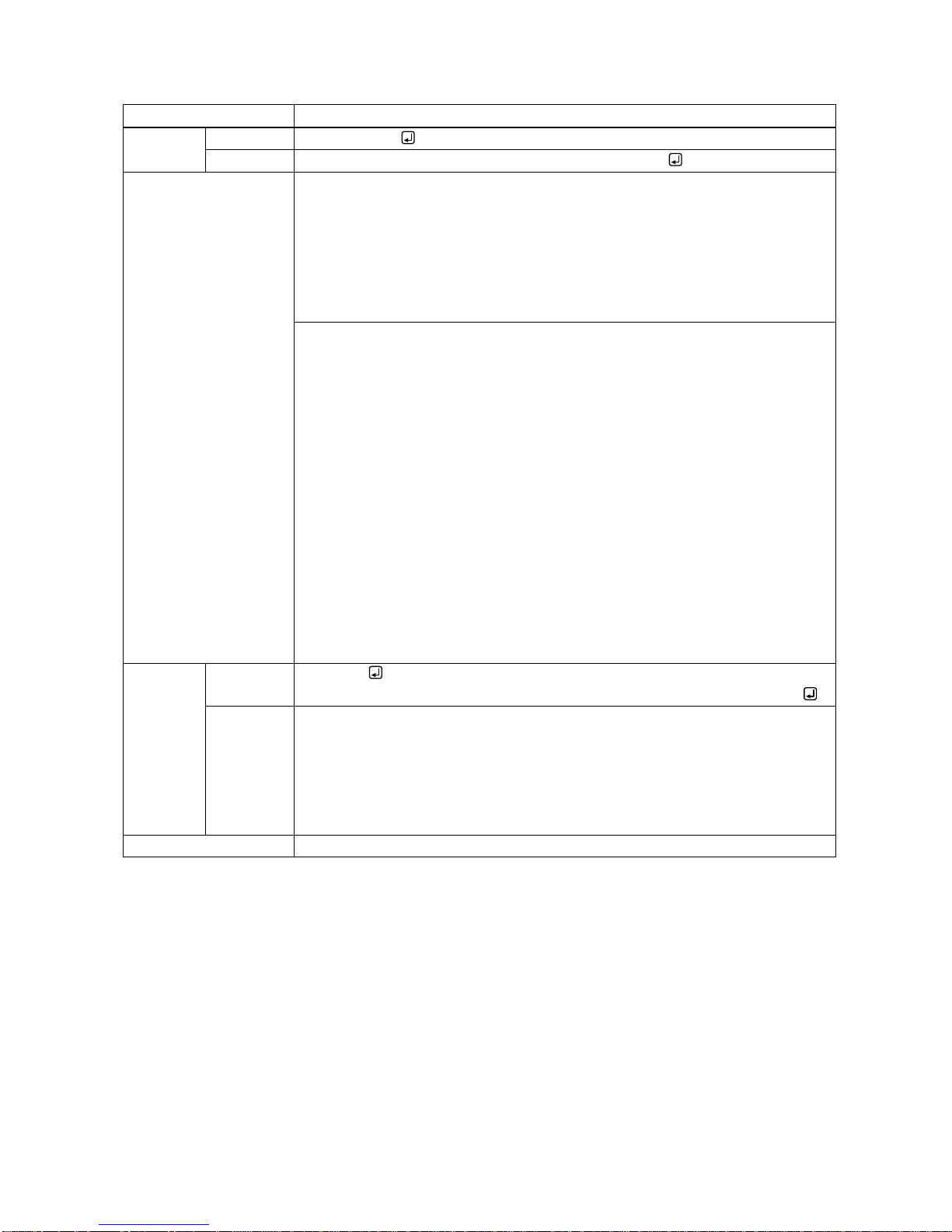
@GES
Monitor’s EDID
Getting
Command
@GES, mode
Response
@GES, mode, status_1 (, status_2, status_3, status_4)
Parameter
mode: Target item
0 = All of 1 to 4,
1 = Monitor’s name*1,
2 = Resolution and dot clock,
3 = HDMI support status, sampling structure, and color depth *2,
4 = Audio support status and sampling frequency, bit length, the number of
channels, and support status of compressed audio *
3
status_1-4: Status
*1
If no sink device is connected, “UNCONNECTED” is returned.
*2
For sink device that does not support HDMI, “DVI” is returned.
For sink device that supports HDMI, “HDMI” is returned, and then supported
sampling structures (RGB, YCbCr 4: 2: 2, YCbCr 4: 4: 4, and YCbCr 4: 2: 0,
separated with “/”) and supported color depths (24, 30, and 36, separated with
“/”) are replied in that order.
*3
For sink device that does not support audio, “AUDIO NOT SUPPORT” is
returned. For sink device that supports audio, “LINEAR PCM” is returned, and
then supported sampling frequencies (32, 44.1, 48, 88.2, 96, 176.4, and 192,
separated with “/”), bit length (16, 20, and 24, separated with “/”), the number of
channels (one of 1 to 8), and “COMPRESSED AUDIO SUPPORT” (if
compressed audio is supported) are replied in that order.
Getting
example
Command
Response
@GES,0
@GES,0,IMP-400UHD,1920x1080 148.50MHz,DVI,AUDIO NOT SUPPORT
Description
Getting the EDID of the sink device connected to OUT1.
・Monitor name: IMP-400UHD
・Resolution: 1920x1080
・Dot clock: 148.50 MHz
・HDMI: Not supported
・Audio: Not supported
Remarks
-
Page 39
IMP-400UHD Command Guide
39
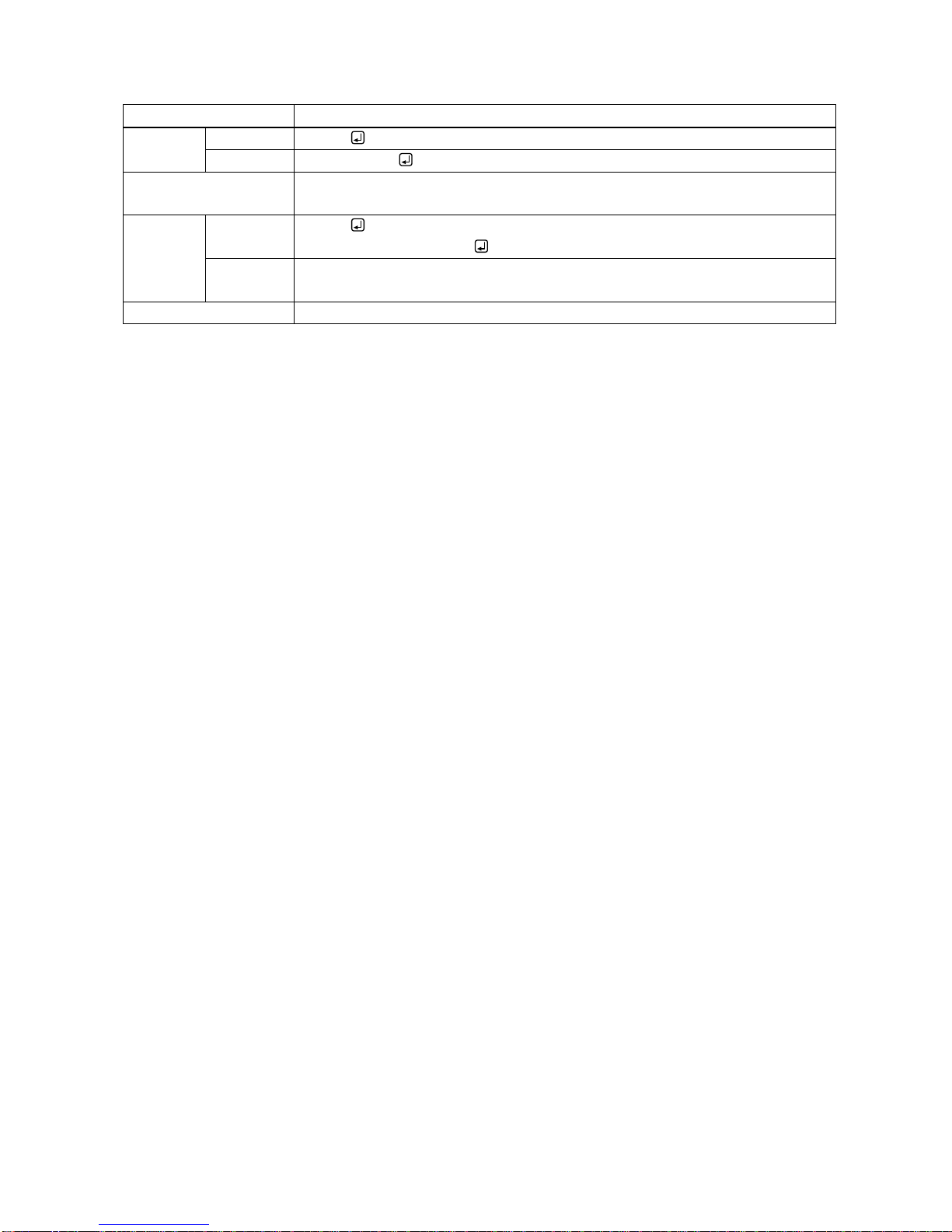
@GIV
Version
Getting
Command
@GIV
Response
@GIV, id, ver
Parameter
id : Model number
ver : Firmware version
Getting
example
Command
Response
@GIV
@GIV,IMP-400UHD,1.00
Description
Getting the product information.
Model number and firmware version are replied.
Remarks
-
Page 40
IMP-400UHD Command Guide
40
IMP-400UHD User’s Guide (Command Guide)
Ver.1.0.0
Issued on: 1 December 2017
Headquarters
IDK Corporation
7-9-1 Chuo, Yamato-shi, Kanagawa-pref.
242-0021 JAPAN
TEL: +81-46-200-0764 FAX: +81-46-200-0765
Email: [email protected] URL: http: //www.idkav.com
USA
IDK America Inc.
72 Grays Bridge Road Suite 1-C, Brookfield, CT 06804
TEL: +1-203-204-2445
Email: [email protected] URL: http: //www.idkav.com
Europe
IDK Europe GmbH
Lise-Meitner-Str. 6, D-40878 Ratingen
TEL: +49-2102-578-301-0
Email: [email protected] URL: http: //www.idkav.com
Product information
Support
Arvanics Corporation
7-9-1 Chuo, Yamato-shi, Kanagawa-pref.
242-0021 JAPAN
TEL: +81-46-259-6920 FAX: +81-46-259-6930
Email: [email protected] URL: http: //www.arvanics.com
Information in this document is subject to change without notice.
All rights reserved. All trademarks mentioned are the property of their respective owners.
 Loading...