

Page 1
POWER
DIGITAL MATRIX SWITCHER
INPUT SELECT
1 2 3 4 5 6
ALL 7 8
OUTPUT SELECT
9 10 11 12 13 14
15 16
FDX-16
1 2 3 4 5 6
OFF 7 8
9 10 11 12 13 14
15 16
1 2 3 4 5 6 7 8
1
2
3
4
IN
OUT
9 10 11 12 13 14 15 16
5
6
7
8
9
10
11
12
13
14
15
16
V&A VIDEO AUDIO
SWITCHING MODE
MENU/SET
ESC
SELECT MODE
OUTPUT
INPUT
PRESET
OUTPUT
INPUT
LOAD
INPUT
~1 4
INPUT
~5 8
INPUT
~9 12
INPUT
~13 16
A D
A D
A D
A D
~1 4
~5 8
~9 12
~13 16
OUTPUT
OUTPUT
OUTPUT
OUTPUT
A D
A D
A D
A D
FG
BREAKER
AC 100-240V
50/60Hz
S/N
OPTIONRS-232C LAN
UPDATE
ALARM
DVI-D(HDMI) DVI-D(HDMI) DVI-D(HDMI) DVI-D(HDMI)
A B C D
DVI-D(HDMI) DVI-D(HDMI) DVI-D(HDMI) DVI-D(HDMI)
A B C D
DVI-D(HDMI) DVI-D(HDMI) DVI-D(HDMI) DVI-D(HDMI)
A B C D
DVI-D(HDMI) DVI-D(HDMI) DVI-D(HDMI) DVI-D(HDMI)
A B C D
A
RX TX RX TX RX TX RX TX
B C D
OPTICAL OPTICAL OPTICAL OPTICAL
A
RX TX RX TX RX TX RX TX
B C D
OPTICAL OPTICAL OPTICAL OPTICAL
LINK LINK LINK LINK
HDBaseTA B C DHDBaseT HDBaseT HDBaseT
LINK LINK LINK LINK
HDBaseTA B C DHDBaseT HDBaseT HDBaseT
Digital Matrix Switcher
FDX-16
<Command Reference Guide>
Ver.1.0.1
● Thank you for choosing our product.
● To ensure the best performance of this product, please read this Command Guide and Users Guide fully
and carefully before using your product and keep this manual beside the product.
IDK Corporation
Page 2

FDX-16 Command Guide
Trademarks
The terms HDMI and HDMI High-Definition Multimedia Interface, and the HDMI Logo are trademarks or
registered trademarks of HDMI Licensing, LLC in the United States and other countries.
HDBaseT™ and the HDBaseT Alliance Logo are trademarks of the HDBaseT Alliance.
All other company and product names mentioned in this manual are either registered trademarks or
trademarks of their respective owners. In this manual, the “®” or “™” marks may not be specified.
2
Page 3

FDX-16 Command Guide
Before reading this manual
● All rights reserved.
● Some of the contents in this command guide such as appearance diagrams, menu operations,
communication commands, and so on may differ from your FDX depending on the version.
● This command guide is subject to change without notice. You can download the latest version from IDK’s
website at: http://www.idk.co.jp/en/index.html
The reference manual for the FDX-16 consists of the following two volumes:
■ Users guide:
Provides explanations and procedures for operations, installation, connections among devices, I/O
adjustment and settings.
■ Command guide (this document): Please download this guide from the website above.
Provides explanations and procedures for external control using RS-232C communication and LAN
communications.
3
Page 4

FDX-16 Command Guide
Table of Contents
1 About this guide ............................................................................................................................................ 5
2 Communication specification ........................................................................................................................ 6
2.1 RS-232C communication ...................................................................................................................... 6
2.1.1 Setup RS-232C communication .................................................................................................... 6
2.1.2 RS-232C connector ....................................................................................................................... 8
2.1.3 Specification of RS-232C communication ..................................................................................... 8
2.2 LAN communication .............................................................................................................................. 9
2.2.1 LAN communication ...................................................................................................................... 9
2.2.2 LAN connector............................................................................................................................. 13
2.2.3 Specification of LAN communication .......................................................................................... 13
2.2.4 The number of TCP-IP connections ............................................................................................ 14
2.3 Command ........................................................................................................................................... 15
2.3.1 Regular command ....................................................................................................................... 15
2.3.2 Compatible mode communication command .............................................................................. 16
2.4 Command list ...................................................................................................................................... 18
2.5 Detailed description ............................................................................................................................ 20
2.5.1 Error status .................................................................................................................................. 20
2.5.2 I/O channel selection ................................................................................................................... 21
2.5.3 Input setting ................................................................................................................................. 24
2.5.4 Output setting .............................................................................................................................. 26
2.5.5 Audio setting................................................................................................................................ 28
2.5.6 EDID setting ................................................................................................................................ 29
2.5.7 RS-232C communication ............................................................................................................ 34
2.5.8 LAN communication .................................................................................................................... 35
2.5.9 Preset memory ............................................................................................................................ 37
2.5.10 Others .......................................................................................................................................... 40
2.5.11 Conversion mode communication command .............................................................................. 45
2.5.12 RS-232C transmission mode ...................................................................................................... 49
4
Page 5
FDX-16 Command Guide
POWER
DIGITAL MATRIX SWITCHER
INPUT SELECT
1 2 3 4 5 6
ALL 7 8
OUTPUT SELECT
9 10 11 12 13 14
15 16
FDX-16
1 2 3 4 5 6
OFF 7 8
9 10 11 12 13 14
15 16
1 2 3 4 5 6 7 8
1
2
3
4
IN
OUT
9 10 11 12 13 14 15 16
5
6
7
8
9
10
11
12
13
14
15
16
V&A VIDEO AUDIO
SWITCHING MODE
MENU/SET
ESC
SELECT MODE
OUTPUT
INPUT
PRESET
OUTPUT
INPUT
LOAD
FDX-16
LAN communication
Control by command
Control by WEB browser
PC PC
PC
RS-232C
communication
Control by command
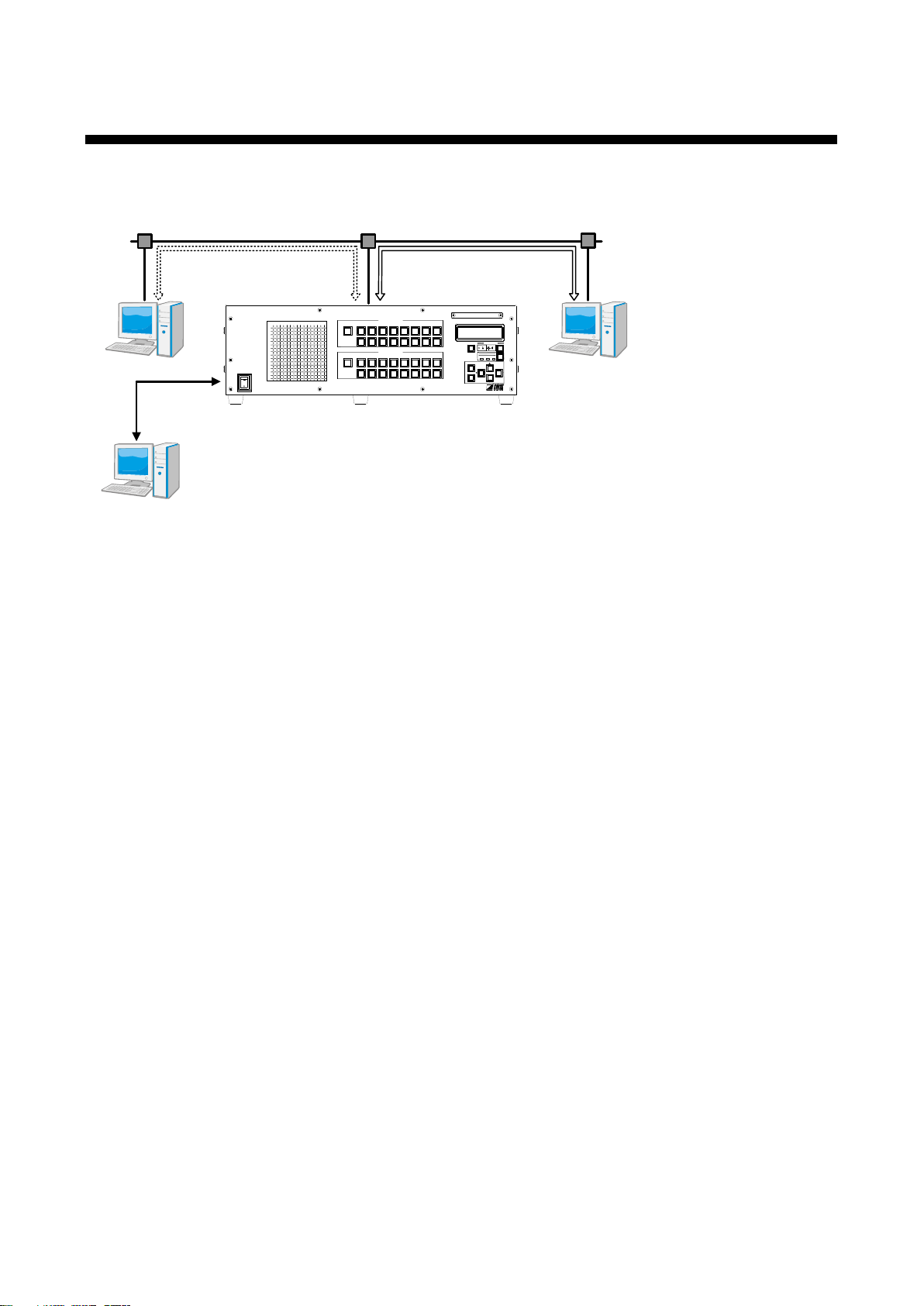
1 About this guide
This guide contains information of communication commands that control the FDX via RS-232C or LAN
communication.
[Fig.1] External control
Mainly the following operations can be controlled by commands:
・Switching channel
・Setting items such as I/O, audio, EDID
・Loading and saving preset memory
5
Page 6
FDX-16 Command Guide
POWER
DIGITAL MATRIX SWITCHER
INPUT SELECT
1 2 3 4 5 6
ALL 7 8
OUTPUT SELECT
9 10 11 12 13 14
15 16
FDX-16
1 2 3 4 5 6
OFF 7 8
9 10 11 12 13 14
15 16
1 2 3 4 5 6 7 8
1
2
3
4
IN
OUT
9 1011 12 13 1415 16
5
6
7
8
9
10
11
12
13
14
15
16
V&A VIDEO AUDIO
SWITCHING MODE
MENU/SET
ESC
SELECT MODE
OUTPUT
INPUT
PRESET
OUTPUT
INPUT
LOAD
INPUT
~
1 4
A D
OPTIO NRS-232C LAN
UPDATE
ALARM
DVI-D(HDMI) DVI-D(HDMI) DVI-D(HDMI) DVI-D(HDMI)
A
B
C D
FDX-16PC
RS-232C cable
Command
RS-232C connector
2 Communication specification
2.1 【RS-232C communication
2.1.1 Setup RS-232C communication
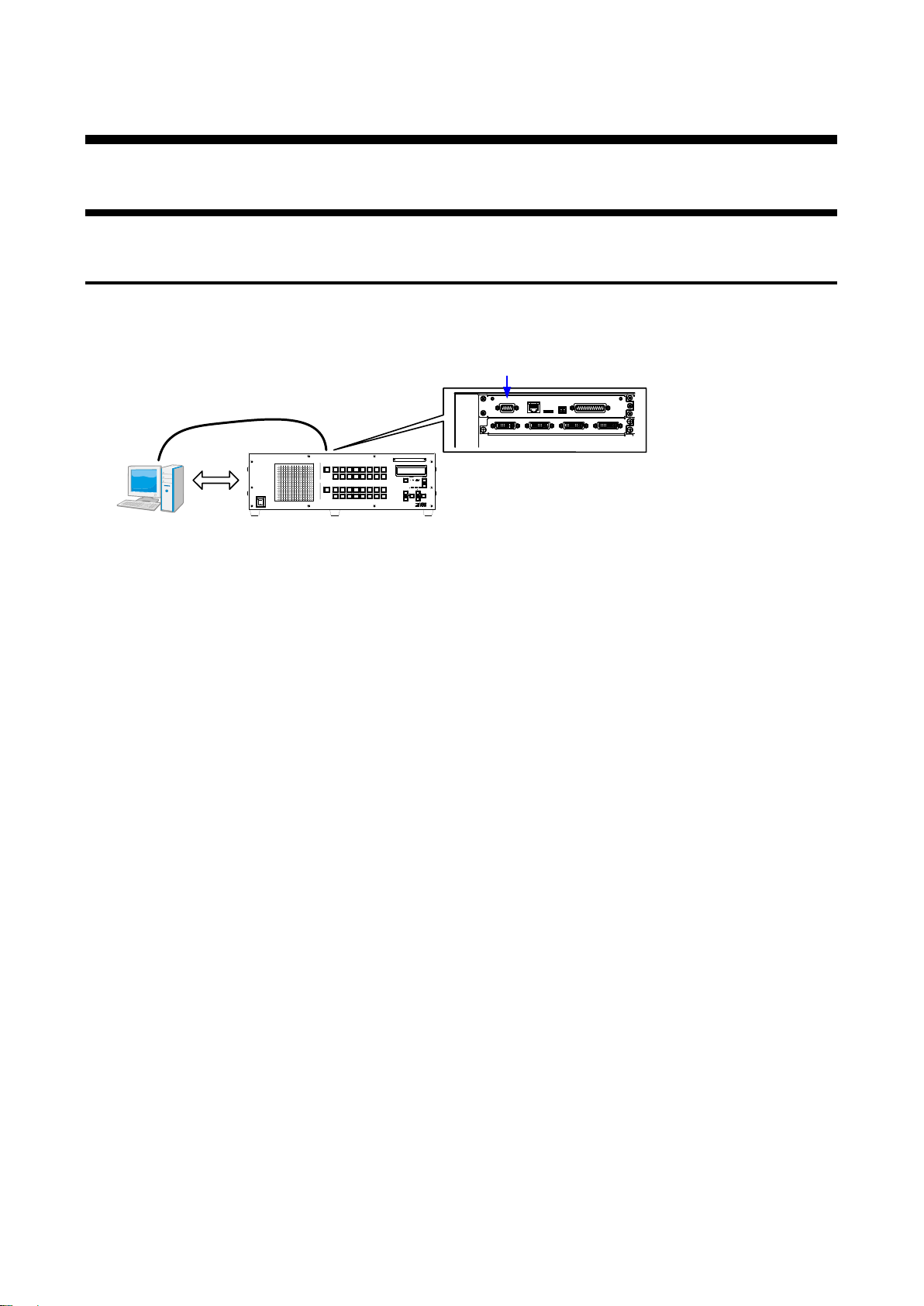
The FDX can be controlled via RS-232C communication. Connect the FDX with a control device (such as PC)
via an RS-232C cable and use commands to control the FDX or acquire its status.
[Fig. 2.1] Connecting control device via RS-232C
6
Page 7
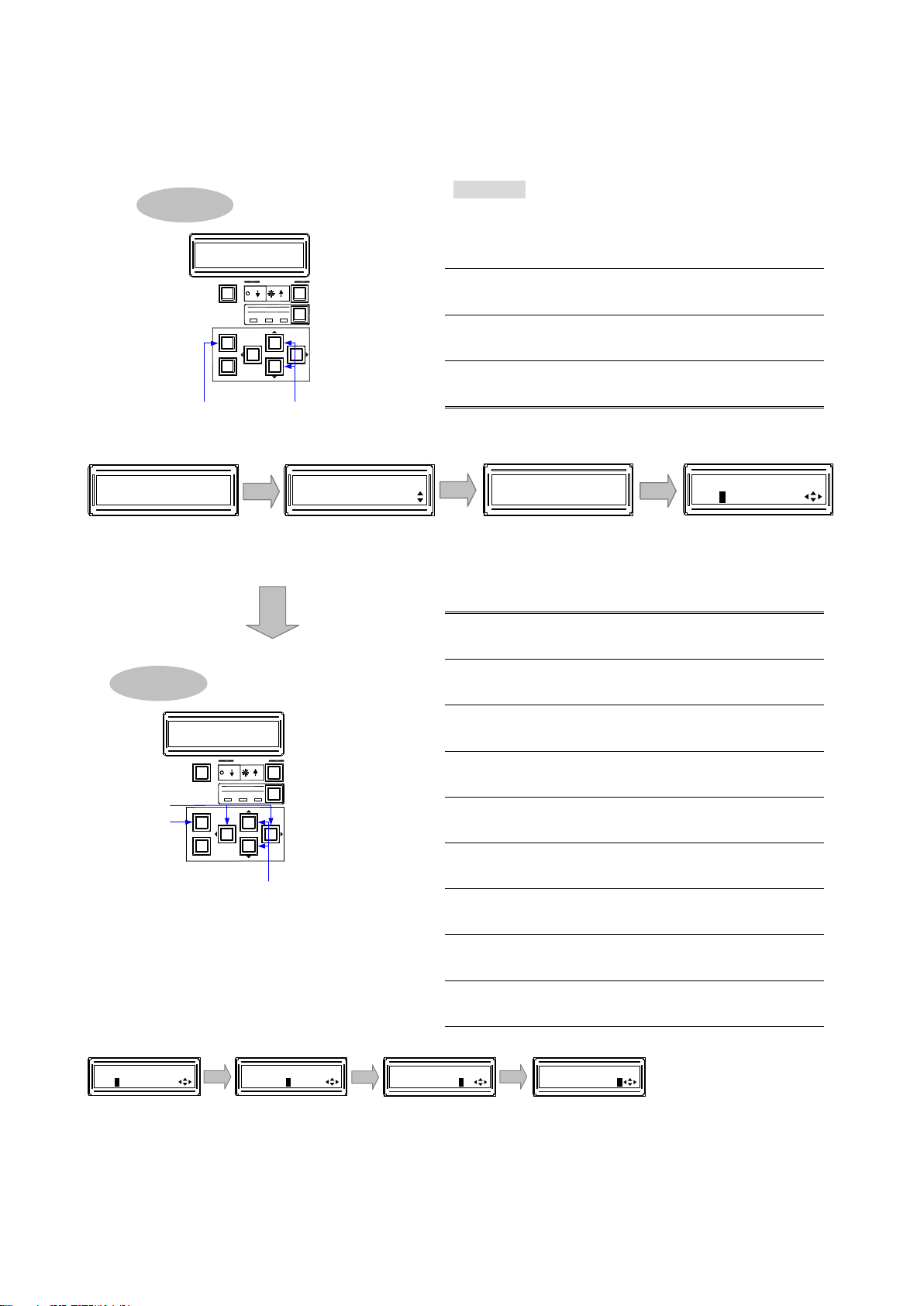
To set RS-232C communication:
Procedure
1
Press the “MENU/SET” key to open the main
menu.
2
Use “▲” and “▼” keys to select “COM
PORT”.
3
Press the “MENU/SET” key to move to the
sub menu.
4
Press the “MENU/SET” key to move the
“COM PORT SETUP” screen.
5
Use the “” and “” keys to move the cursor
to the baud rate.
6
Use “▲” and “▼” keys to select the baud
rate.
7
Use the “” and “” keys to move the cursor
to the data bit length.
8
Use “▲” and “▼” keys to select the data bit
length.
9
Use the “” and “” keys to move the cursor
to the parity check.
10
Use “▲” and “▼” keys to select the parity
check.
11
Use the “” and “” keys to move the cursor
to the stop bit.
12
Use “▲” and “▼” keys to select the stop bit.
13
Press the “MENU/SET” key to apply the
settings.
5, 6 7, 8 9, 10
Baud rate
Data bit
Parity check Stop bit
11, 12, 13
[COM PORT SETUP]
9600bps 8 NONE 1
[COM PORT SETUP]
9600bps 8 NONE 1
[COM PORT SETUP]
9600bps 8 NONE 1
[COM PORT SETUP]
9600bps 8 NONE 1
6, 8, 10, 12
5, 7, 9, 11
Changing settings
V&A VIDEO A UDIO
SWITCHING MODE
MENU/SET
ESC
SELECT MODE
OUTPUT
INPUT
PRESET
OUTPUT
INPUT
LOAD
13
[FUNCTION SELECT]
COM PORT
[COM PORT]
COM PORT SETUP
2, 3 4
Main menu
Sub menu
Setting screen
[COM PORT SETUP]
9600bps 8 NONE 1
FDX-16
16x16 Matrix
1
Top screen
Selecting Menu
21, 3, 4
V&A VIDEO AUDI O
SWITCHING MODE
MENU/SET
ESC
SELECT MODE
OUTPUT
INPUT
PRESET
OUTPUT
INPUT
LOAD
【See 2.1.3 Specification of RS-232C communication】
[Fig. 2.2] Setup RS-232C communication
FDX-16 Command Guide
7
Page 8
FDX-16 Command Guide
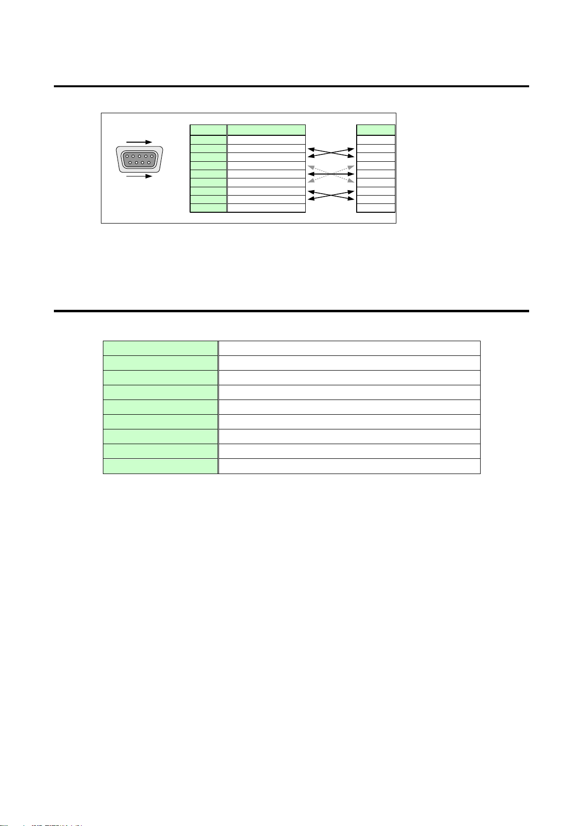
D-sub 9 Pin male
1 5
RS-232C
connector
6 9
RD
TD
NC
NC
NC
NC
GND
RTS
CTS
Pin#
1
3
2
4
6
5
7
9
8
Signal
RD
TD
NC
NC
NC
NC
GND
RTS
CTS
Signal
(Received data)
(Transmitted data)
(Ground)
(Request to Send)
(Clear to Send)
MSD
Cross
Cable
Control Unit
(Rear panel)
(No connection)
(No connection)
(No connection)
(No connection)
Compliant standard
RS-232C
Baud rate
4800, 9600, 14400, 19200, 38400 [bps]
Data bit
7, 8 [bit]
Parity check
None, even, odd
Stop bit
1, 2 [bit]
X parameter
Invalid
Flow control
None
Delimiter
CR LF (Carriage return and line feed, 0D and 0A in hex)
Communication method
Full duplex
2.1.2 RS-232C connector
RS-232C pin assignments
[Fig. 2.3] RS-232C connector
2.1.3 Specification of RS-232C communication
[Table 2.1] RS-232C specification
8
Page 9
FDX-16 Command Guide
POWER
DIGITAL MATRIX SWITCHER
INPUT SELECT
1 2 3 4 5 6
ALL 7 8
OUTPUT SELECT
9 10 11 12 13 14
15 16
FDX-16
1 2 3 4 5 6
OFF 7 8
9 10 11 12 13 14
15 16
1 2 3 4 5 6 7 8
1
2
3
4
IN
OUT
9 10 11 1213 14 15 16
5
6
7
8
9
10
11
12
13
14
15
16
V&A VIDEO AUDIO
SWITCHING MODE
MENU/SET
ESC
SELECT MODE
OUTPUT
INPUT
PRESET
OUTPUT
INPUT
LOAD
LAN connector
LAN
Command
INPUT
~
1 4
A D
OPTIO N
RS-232C
LAN
UPDATE
ALARM
DVI-D(HDMI) DVI-D(HDMI) DVI-D(HDMI) DVI-D(HDMI)
A B C D
FDX-16
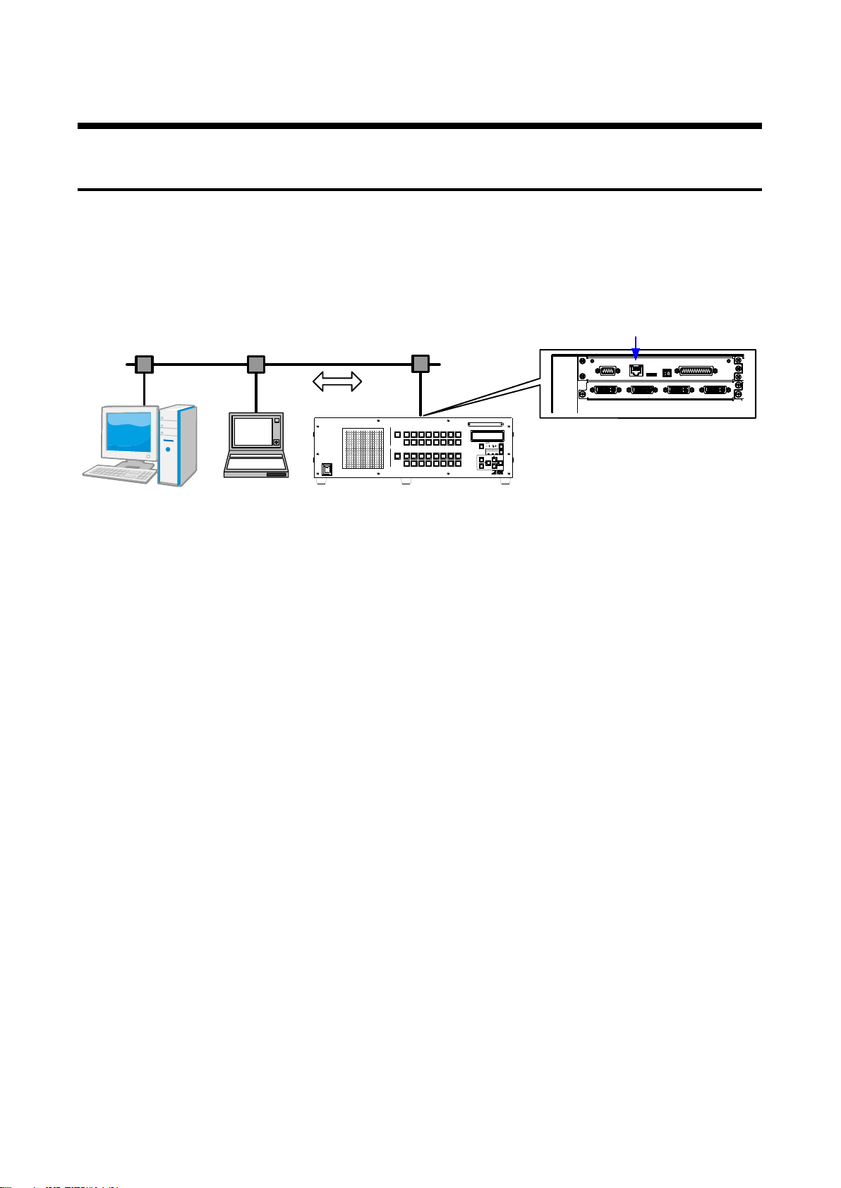
2.2 LAN communication
2.2.1 LAN communication
The FDX can be controlled via LAN communication. Connect the FDX with a control device (such as PC) via
an LAN cable and use commands to control the FDX and acquire its status.
For command control, use ports 6000 to 6999 or 1100. If no command is sent for 30 seconds after connection
established, the connection will be disconnected.
[Fig. 2.4] LAN connection
9
Page 10
FDX-16 Command Guide
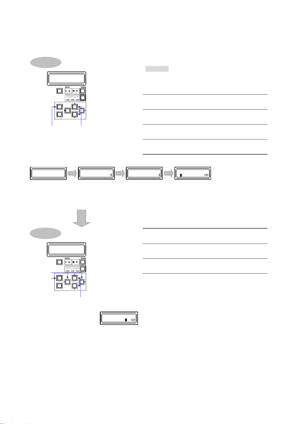
Procedure
1
Press the “MENU/SET” key to open the main
menu.
2
Use “▲” and “▼” keys to select “LAN”.
3
Press the “MENU/SET” key to open the sub
menu.
4
Use “▲” and “▼” keys to select “IP ADDRESS”.
5
Press the “MENU/SET” key to open the setting
screen.
6
Use the “” and “” keys to move the cursor to
each digit.
7
Use “▲” and “▼” keys to select the value.
8
Press the “MENU/SET” key to apply the
settings.
7
6
8
V&A VIDEO AUDI O
SWITCHING MODE
MENU/SET
ESC
SELECT MODE
OUTPUT
INPUT
PRESET
OUTPUT
INPUT
LOAD
Changing setting
Selecting menu
2、41、3、5
V&A VIDEO AUDIO
SWITCHING MODE
MENU/SET
ESC
SELECT MODE
OUTPUT
INPUT
PRESET
OUTPUT
INPUT
LOAD
[LAN]
IP ADDRESS
2, 3 4, 5
Main manu Sub menu
Setting screen
[FUNCTION SELECT]
LAN
[IP ADDRESS]
192.168.001.199
FDX-16
16x16 Matrix
1
Top screen
6, 7, 8
Setting IP address
[IP ADDRESS]
192.168.001.199
To set LAN communication: Setting IP address, subnet mask, and port number.
■ IP address
[Fig. 2.5] Setting IP address
10
Page 11
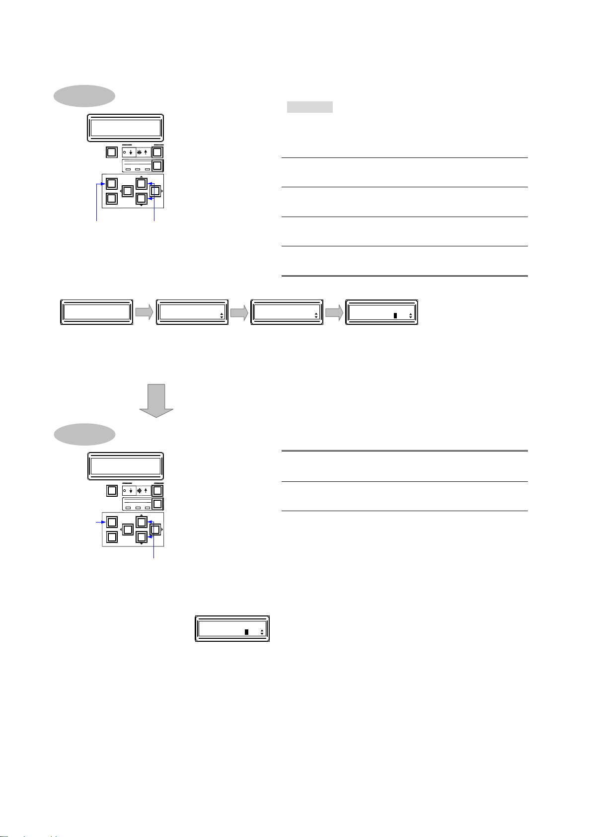
■ Subnet mask
Procedure
1
Press the “MENU/SET” key to open the main
menu.
2
Use “▲” and “▼” keys to select “LAN”.
3
Press the “MENU/SET” key to open the sub
menu.
4
Use “▲” and “▼” keys to select “SUBNET
MASK”.
5
Press the “MENU/SET” key to open the setting
screen.
6
Use “▲” and “▼” keys to select the value.
7
Press the “MENU/SET” key to apply the
settings.
6, 7
Setting subnet mask
[SUBNET MASK]
255.255.255.000
[FUNCTION SELECT]
LAN
[LAN]
SUBNET MASK
2, 3
4, 5
Main menu
Sub menu
[SUBNET MASK]
255.255.255.000
Setting screen
FDX-16
16x16 Matrix
1
Top screen
Selecting menu
2, 41, 3, 5
V&A VIDEO AUDIO
SWITCHING MODE
MENU/SET
ESC
SELECT MODE
OUTPUT
INPUT
PRESET
OUTPUT
INPUT
LOAD
7
6
V&A VIDEO AUDI O
SWITCHING MODE
MENU/SET
ESC
SELECT MODE
OUTPUT
INPUT
PRESET
OUTPUT
INPUT
LOAD
Changing setting
[Fig. 2.6] Setting subnet mask
FDX-16 Command Guide
11
Page 12
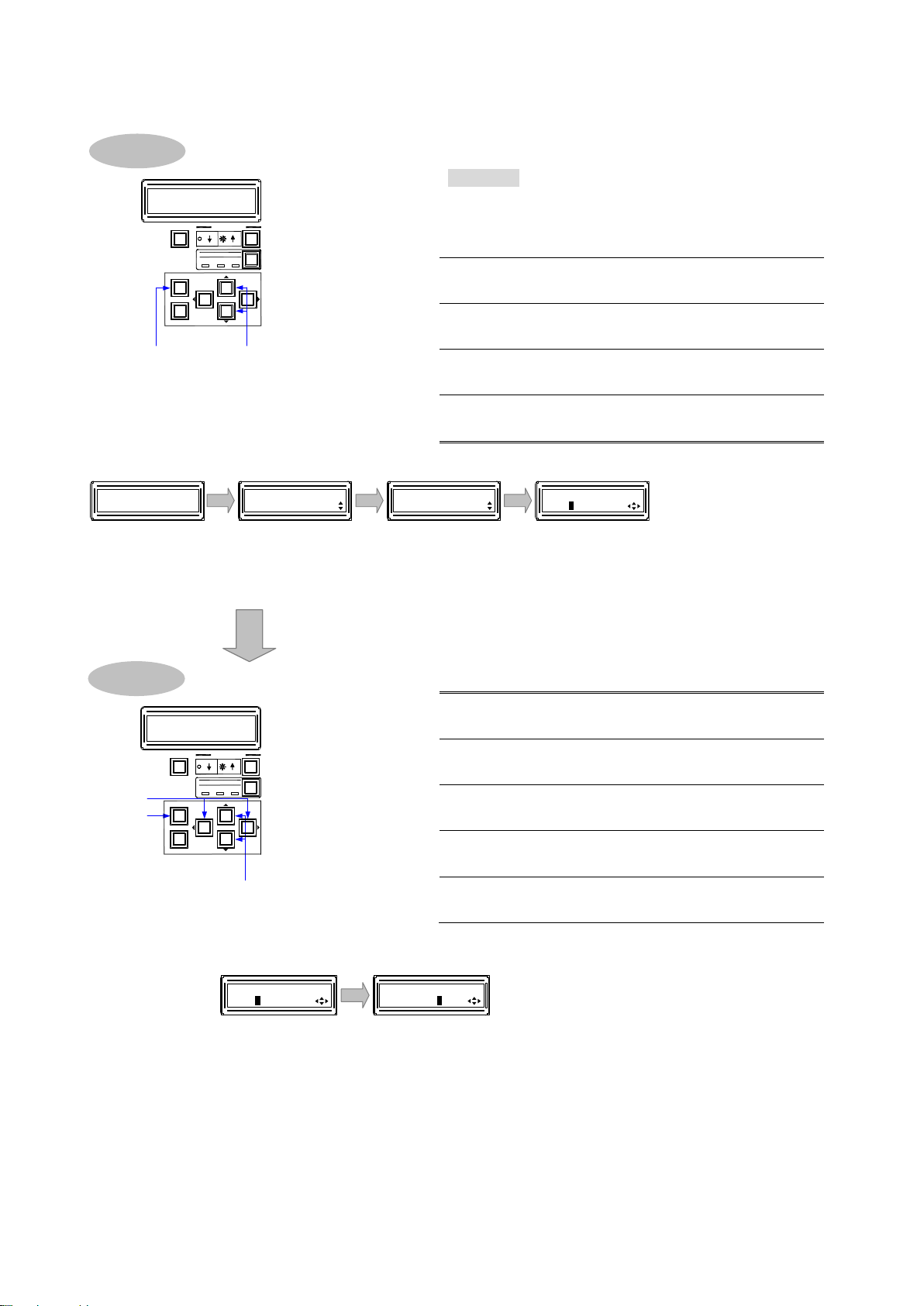
FDX-16 Command Guide
Procedure
1
Press the “MENU/SET” key to open the main
menu.
2
Use “▲” and “▼” keys to select “LAN”.
3
Press the “MENU/SET” key to open the sub
menu.
4
Use “▲” and “▼” keys to select “CONTROL
PORT”.
5
Press the “MENU/SET” key to open the
setting screen.
6
Use the “” and “” keys to move the cursor
to the port number (“1”).
7
Use “▲” and “▼” keys to select the port
number.
8
Use the “” and “” keys to move the cursor
to the 8 connection setting (“2”).
9
Use “▲” and “▼” keys to select “OFF” or
“ON”.
10
Press the “MENU/SET” key to apply the
settings.
[CONTROL PORT]
1:1100 2:OFF
8, 9, 10
Setting 8 connection (“2”)
6, 7
Setting port number (“1”)
[CONTROL PORT]
1:1100 2:OFF
[FUNCTION SELECT]
LAN
[LAN]
CONTROL PORT
2, 3
4, 5
Main menu
Sub menu
FDX-16
16x16 Matrix
1
Top screen
[CONTROL PORT]
1:1100 2:OFF
Setting screen
Selecting menu
2, 41, 3, 5
V&A VIDEO AUDIO
SWITCHING MODE
MENU/SET
ESC
SELECT MODE
OUTPUT
INPUT
PRESET
OUTPUT
INPUT
LOAD
7, 9
6, 8
10
V&A VIDEO AUD IO
SWITCHING MODE
MENU/SET
ESC
SELECT MODE
OUTPUT
INPUT
PRESET
OUTPUT
INPUT
LOAD
Changing setting
■ TCP port number
[Fig. 2.7] Setting TCP port number
12
Page 13
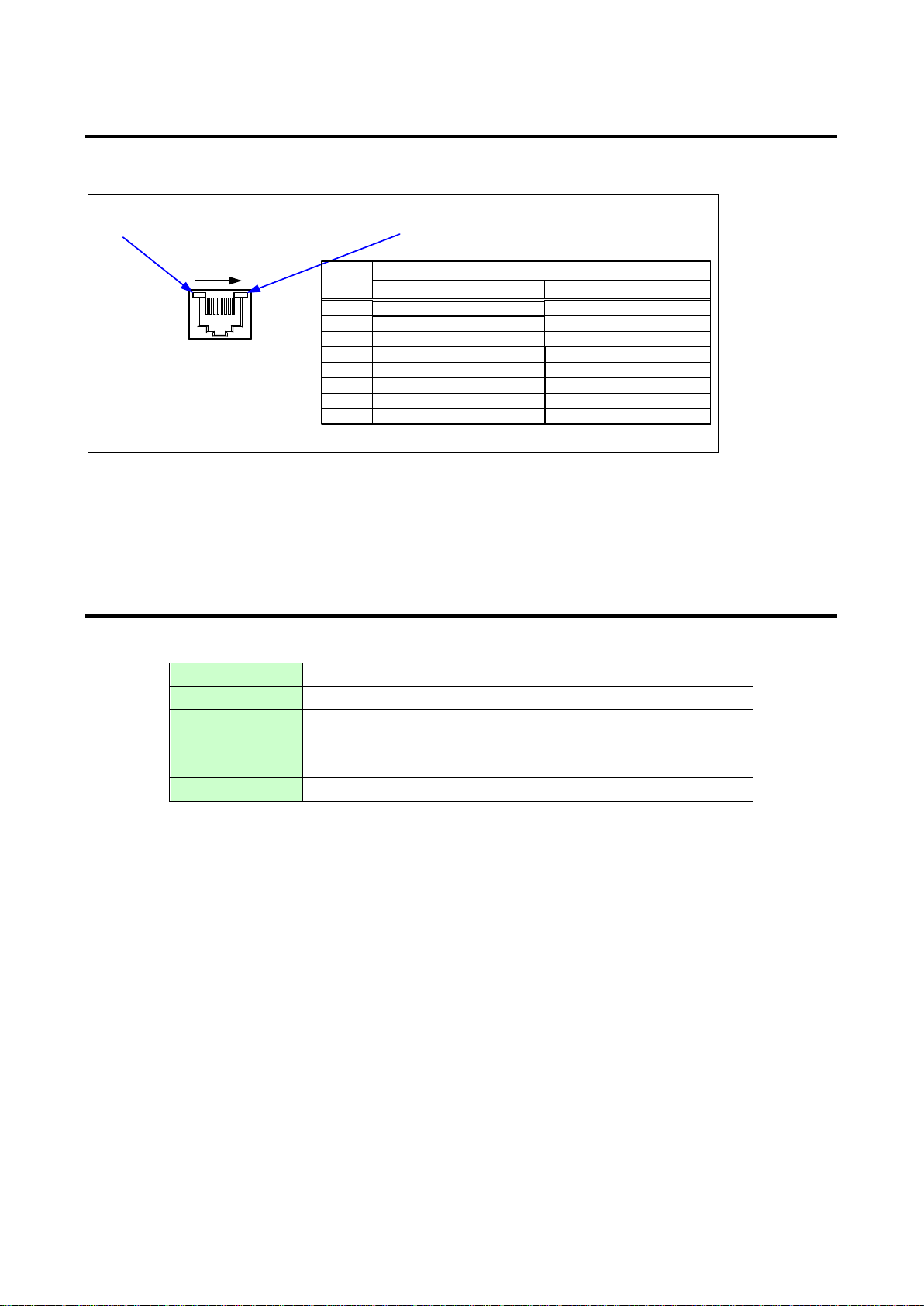
FDX-16 Command Guide
81
LAN Connector
8pin RJ-45 connector
(FDX’s rear panel)
Lights in green when the link is established.
Lights in orange when data can be
sent/received. Blinks in orange while data is
being sent/received.
RX+: Received Data+
N.C: No connection
TX+: Transmitted Data+
Pin #
1
3
2
4
6
5
7
Signal Name
TX-: Transmitted Data-
N.C: No connection
RX-: Received Data-
N.C: No connection
N.C: No connection
MDI
TX+: Transmitted Data+
N.C: No connection
RX+: Received Data+
RX-: Received Data-
N.C: No connection
TX-: Transmitted Data-
N.C: No connection
N.C: No connection
MDI-X
8
Physical layer
10BASE-T (IEEE802.3i)/100Base-TX (IEEE802.3u)
Network layer
ARP, IP, ICMP
Transport layer
TCP
Port used for command control: 23, 1100, 6000 to 6999
Port used for WEB browser control (HTTP): 80, 5000 to 5999
Application layer
HTTP, TELNET
2.2.2 LAN connector
LAN connector pin assignments:
[Fig. 2.8] Specification of LAN connector
The FDX supports Auto MDI/MDI-X, which distinguishes/switches straight and cross cables automatically.
2.2.3 Specification of LAN communication
[Table 2.2] Specification of LAN communication
Note: Up to 8 connections can be used simultaneously.
【See 2.2.4 The number of TCP-IP connections】
13
Page 14
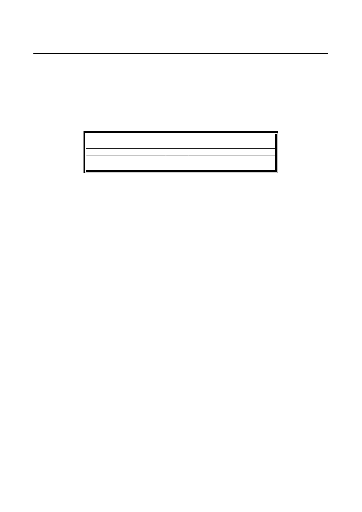
FDX-16 Command Guide
Your PC software
FDX-16
TCP-IP connection
→
(1 port occupied)
Send command (@xxx)
→
←
The command (@xxx) replied
TCP-IP close
→
(1 port released)
2.2.4 The number of TCP-IP connections
The FDX series can connect up to eight connections (eight ports) simultaneously. If the FDX is controlled from
nine or more PCs, they may not be connected to the FDX normally, since the number of connections that can
be used simultaneously is limited.
If you use nine connections or more, TCP-IP connection will be executed/closed every time the
communication command is sent or received from the software of user’s side. By doing so, FDX’s ports are
occupied or released so that nine or more connections can be connected logically.
[Table 2.3] Increasing connections
Note: If any command is not sent from the PC to the FDX for 30 seconds, the FDX disconnects the
connection to avoid the limitation problem on the number of connections. As a result, connection needs
to be established again from the PC side after the current connection of the PC is disconnected.
(Since the number of ports in the FDX is eight, ports are occupied permanently if the PC is turned off
while connections are valid. To prevent this, the FDX disconnects connections if no communication
command is sent from the PC side.)
14
Page 15
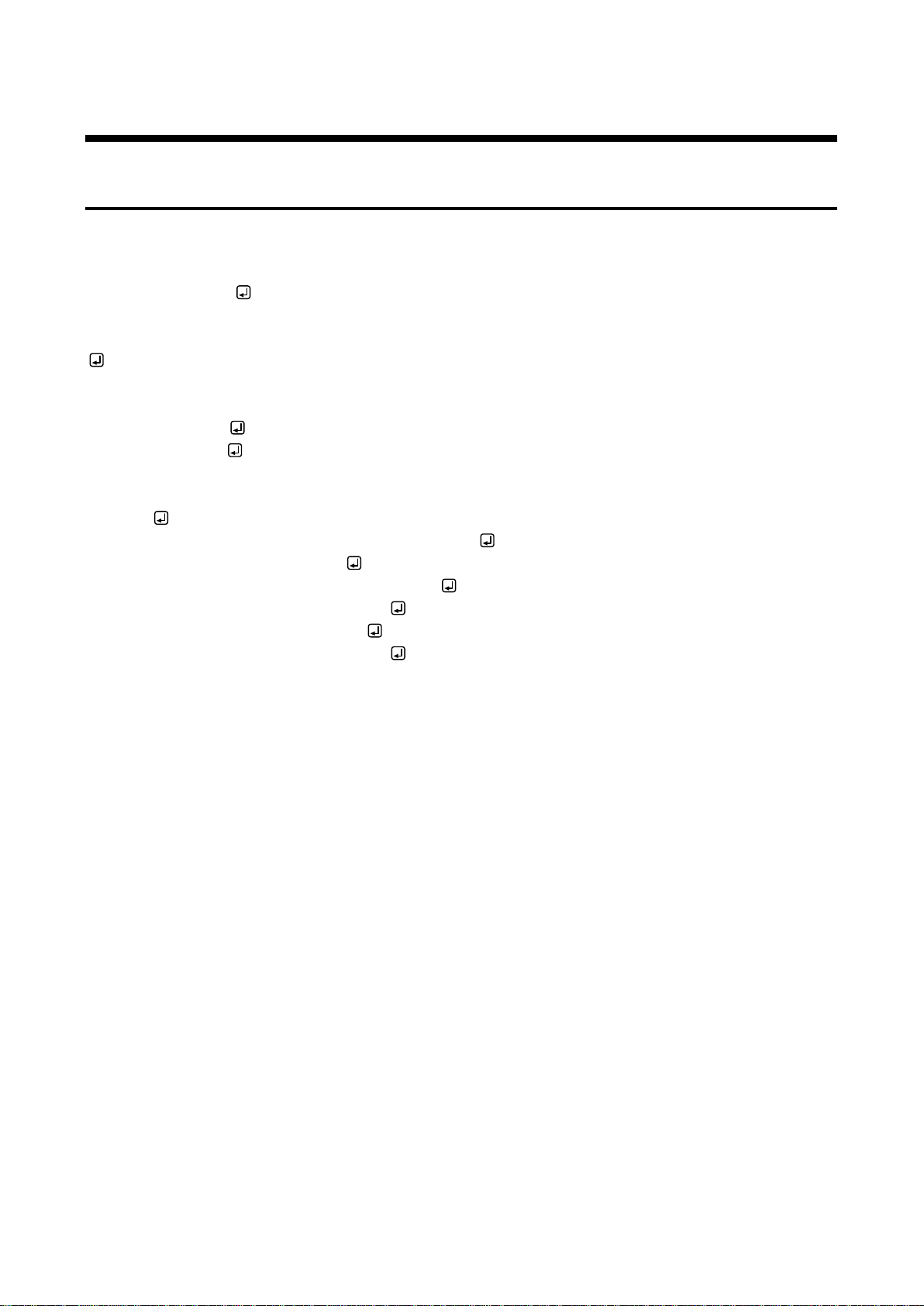
FDX-16 Command Guide
2.3 Command
2.3.1 Regular command
A command consists of “@” (“40” in hex), 3 one-byte alphabetical characters (upper and lower cases), and
parameters (one-byte numbers). For some commands, several parameters can be specified or no parameter
is required. Processing is executed by sending a delimiter at the end of the command.
Example: @SPM,2
“,”( a comma, “2C” in hex) is used between a command and parameter and between two parameters.
: delimiter CR LF (return+line feed, “0D” and “0A” in hex)
An error command is returned if an undefined command or wrong parameter is included.
Example: @SSW,1
@ERR,1
If only a delimiter is sent, a list of help commands is returned.
Example:
- HELP (1/8) - (CHANNEL SELECT Command)
@IOS : Input/Output Select
@GVA : Get Cross Point Video and Audio
@IOV : Input/Output Video Select
@GCP : Get Cross Point Video
@IOA : Input/Output Audio Select
15
Page 16
FDX-16 Command Guide
Procedure
1
Press the “MENU/SET” key to open the main
menu.
2
Use “▲” and “▼” keys to select “OTHERS”.
3
Press the “MENU/SET” key to open the sub
menu.
4
Use “▲” and “▼” keys to select “COMMAND
FORMAT”.
5
Press the “MENU/SET” key to open the
setting screen.
6
Use “▲” and “▼” keys to select
“OPTION”.
Setting command mode
[COMMAND FORMAT]
OPTION
6
[COMMAND FORMAT]
STANDARD
[FUNCTION SELECT]
OTHERS
[OTHERS]
COMMAND FORMAT
2, 3
4, 5
Main menu
Sub menu
FDX-16
16x16 Matrix
1
Top screen
Setting screen
[COMMAND FORMAT]
STANDARD
Setting menu
2, 41, 3, 5
V&A VIDEO AUDIO
SWITCHING MODE
MENU/SET
ESC
SELECT MODE
OUTPUT
INPUT
PRESET
OUTPUT
INPUT
LOAD
6
V&A VIDEO AUDIO
SWITCHING MODE
MENU/SET
ESC
SELECT MODE
OUTPUT
INPUT
PRESET
OUTPUT
INPUT
LOAD
Changing setting
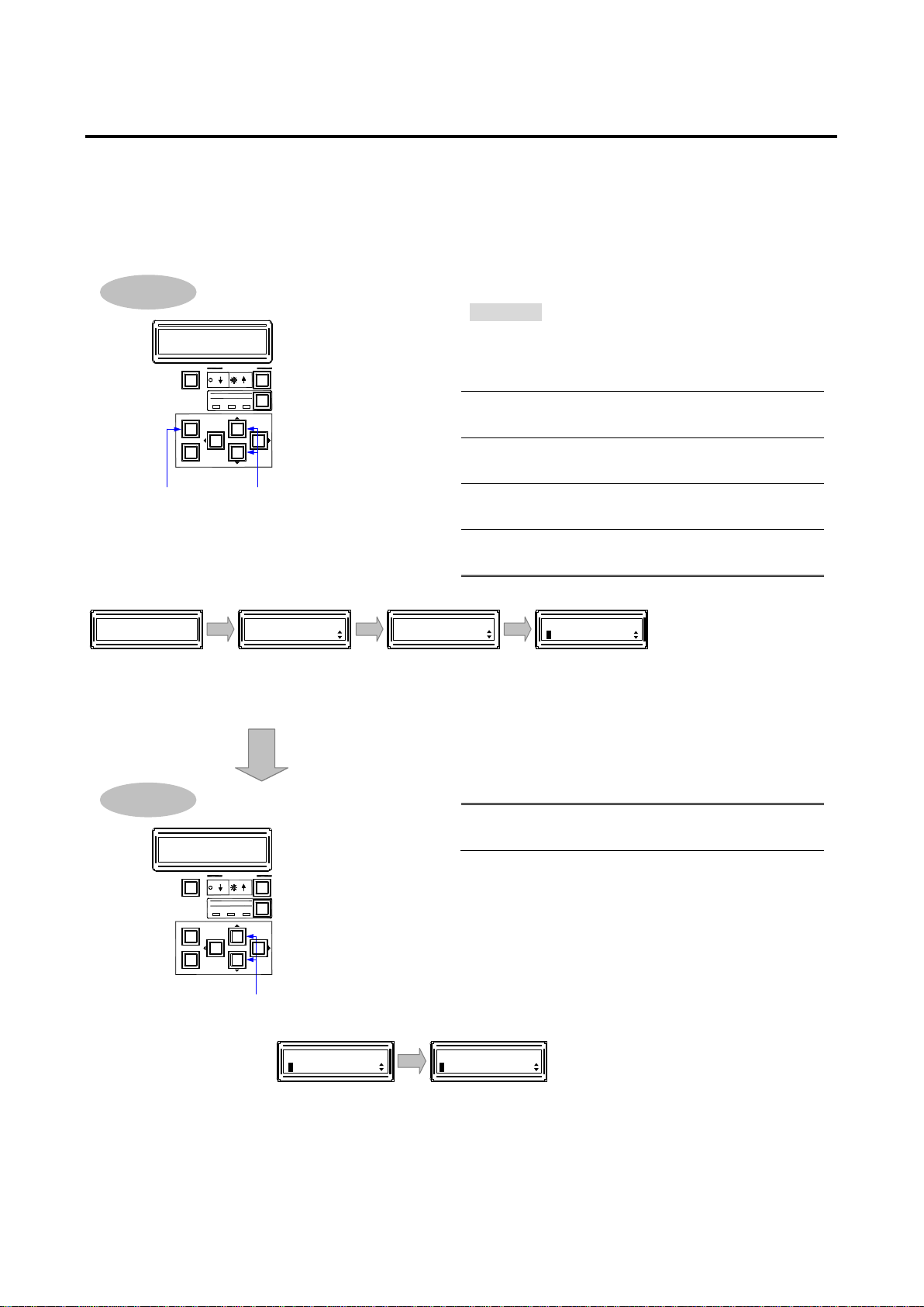
2.3.2 Compatible mode communication command
The FDX can be controlled by compatible mode communication command. To use this command, change the
setting of communication command mode as follows.
■Compatible mode communication command
[Fig. 2.9] Setting compatible mode communication command
16
Page 17

FDX-16 Command Guide
A command consists of one-byte alphabetical characters (upper and lower cases) and parameters (one-byte
numbers). Processing is executed by sending a delimiter at the end of the command.
Example: s,3
“,”( a comma, “2C” in hex) is used between a command and parameter and between two parameters.
: delimiter CR (return, “0D” in hex)
Example: wva
001;002;003;004;005;006;007;008;009;010;011;012;013;014;015;016/001;002;003;004;005;006;007;00
8;009;010;011;012;013;014;015;016
“;” (a semicolon, “3B” in hex) is used between input channel and output channel.
“/” (a slash, “2F” in hex) is used between the FDX and MAU-1616 (optional).
17
Page 18
FDX-16 Command Guide
Command
Function
@ERR
Error status
Command
Function
@GVA / @IOS
Switching I/O channels of FDX and MAU-1616 (optional) simultaneously
@GCP / @IOV
Switching only FDX I/O channel
@GCA / @IOA
Switching only MAU-1616 I/O channel
@SSC
Straight Switching* I/O of FDX and MAU-1616
@SSV
Straight Switching IO of FDX
@SSA
Straight Switching IO of MAU-1616
Command
Function
@GIQ / @SIQ
Input equalizer
@GDT / @SDT
No-signal-input monitoring
@GHE / @SHE
HDCP input enabled/disabled
Command
Function
@GEQ / @SEQ
Output equalizer
@GDM / @SDM
Output mode
@GHM / @SHM
Forcibly HDMI signal output
@GMK / @SMK
Time for ignoring video output request signals
Command
Function
@GDO / @SDO
Digital audio output
Command
Function
@GED / @SED
EDID
@RME
Copying EDID
@GEC / @SEC
EDID loading channel
@GDI / @SDI
Deep Color input
@GSP / @SSP
The number of audio channels
@GAF / @SAF
Audio format
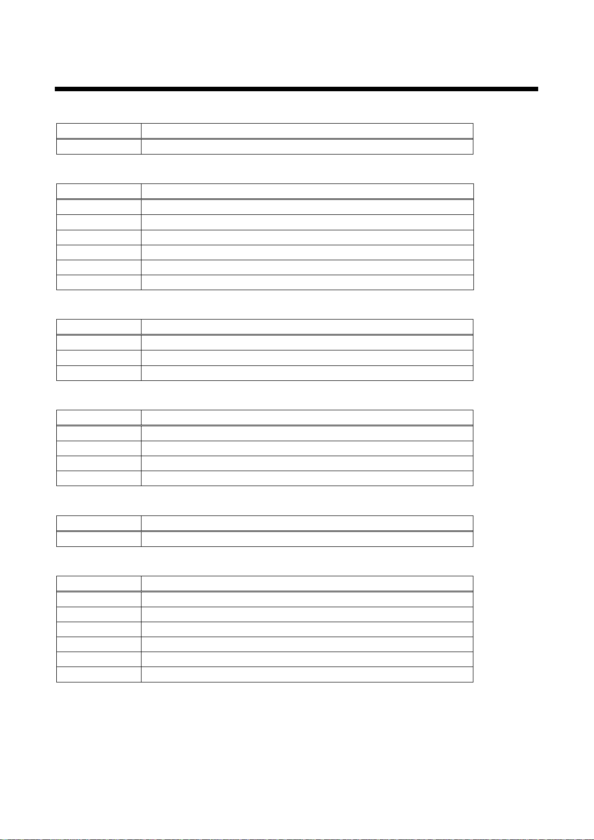
2.4 Command list
Error status
I/O channel selection
Input setting
Output settings
Audio
EDID
18
Page 19
Command
Function
@GCT / @SCT
RS-232C
Command
Function
@GIP / @SIP
IP
@GSB / @SSB
Subnet mask
@GLP / @SLP
TCP port number
@GMC
MAC address
Command
Function
@RPM
Loading preset memory
@SPM
Saving preset memory
@SEM
Saving preset memor
@GCM / @ECM
Editing preset memory
@GPM
Preset memory number matching current I/O channel status
Command
Function
@GLM / @SLM
Key lock
@GST
Slot board
@GSS
Slot board mounting status
@GIV
Version
@GIS
Input signal status
@GOS
Sink device status
@GFS
Cooling fan status
@GPS
Voltage status
Command
Function
mode / AV / V / A
Switching mode
z
Switching I/O channel
wva / w / wa
I/O channel
y / s / t
Getting/saving/calling preset memory
ky / kl / ku
Key lock status/setting key lock/releasing key lock
mem
Preset memory number matching I/O channel status
Command
Function
@G++ / @S++
RS-232C transmission sending channel
@G+R / @S+R
RS-232C transmission receiving channel
@S+S
RS-232C
RS-232C communication
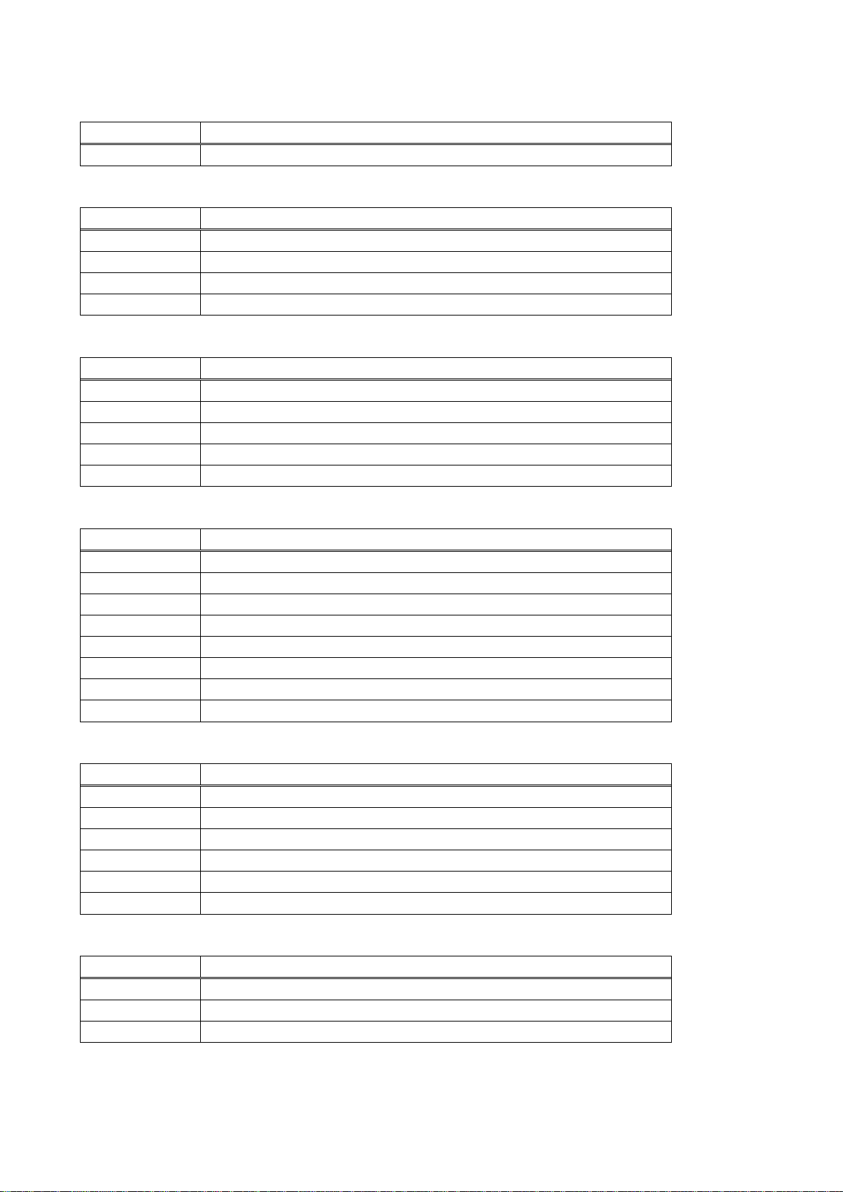
LAN communication
Preset memory
FDX-16 Command Guide
Others
Compatible mode communication command
RS-232C transmission mode
19
Page 20
FDX-16 Command Guide
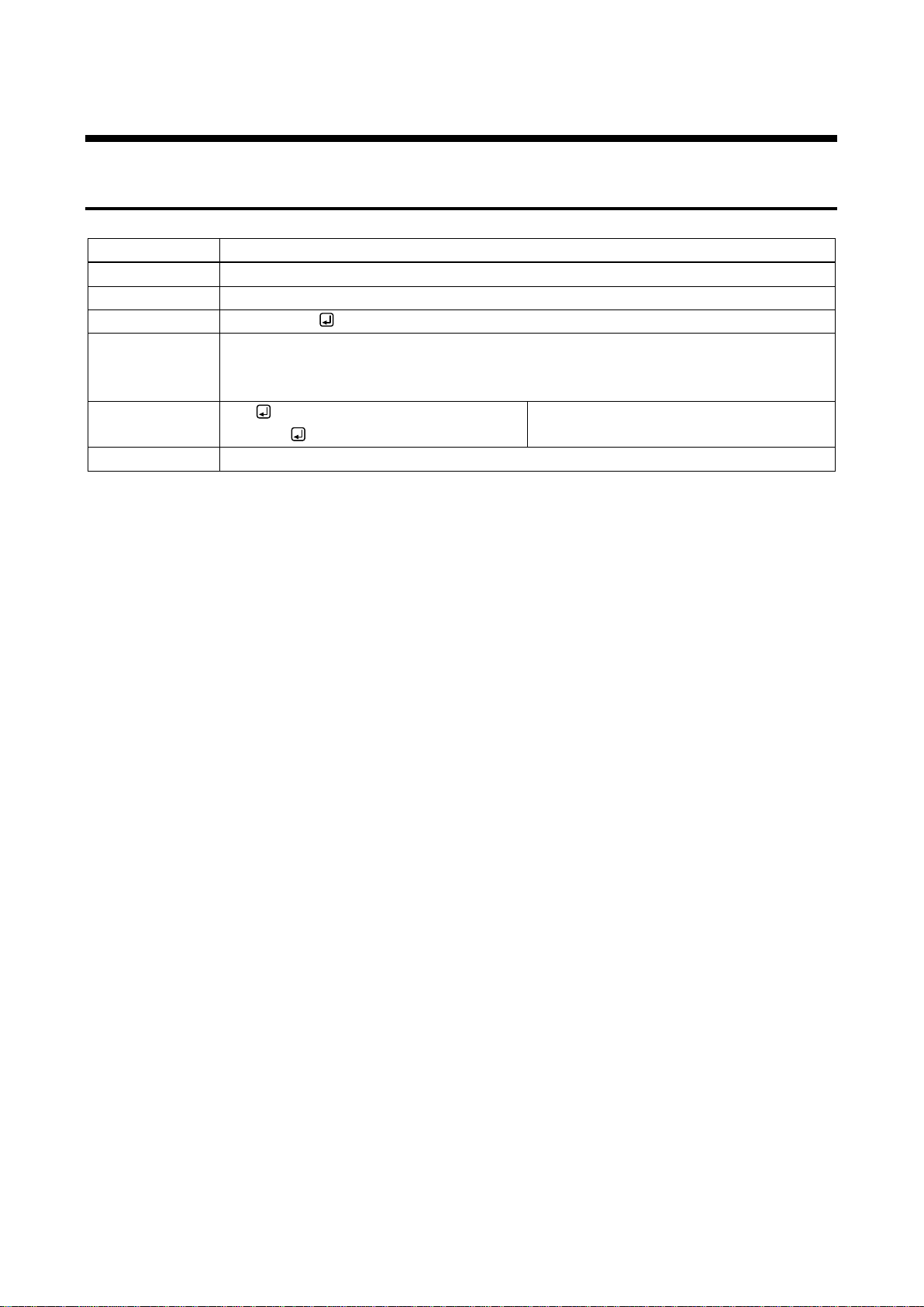
@ERR
Error status
Function
Getting
Format
Only return value
Return value
@ERR, error
Parameter
error: error status
1 = Wrong parameter format or value
2 = Undefined command or wrong format
Example
IOS
@ERR,2
Sending @IOS command.
Command format error
Remarks
-
2.5 Detailed description
2.5.1 Error status
20
Page 21
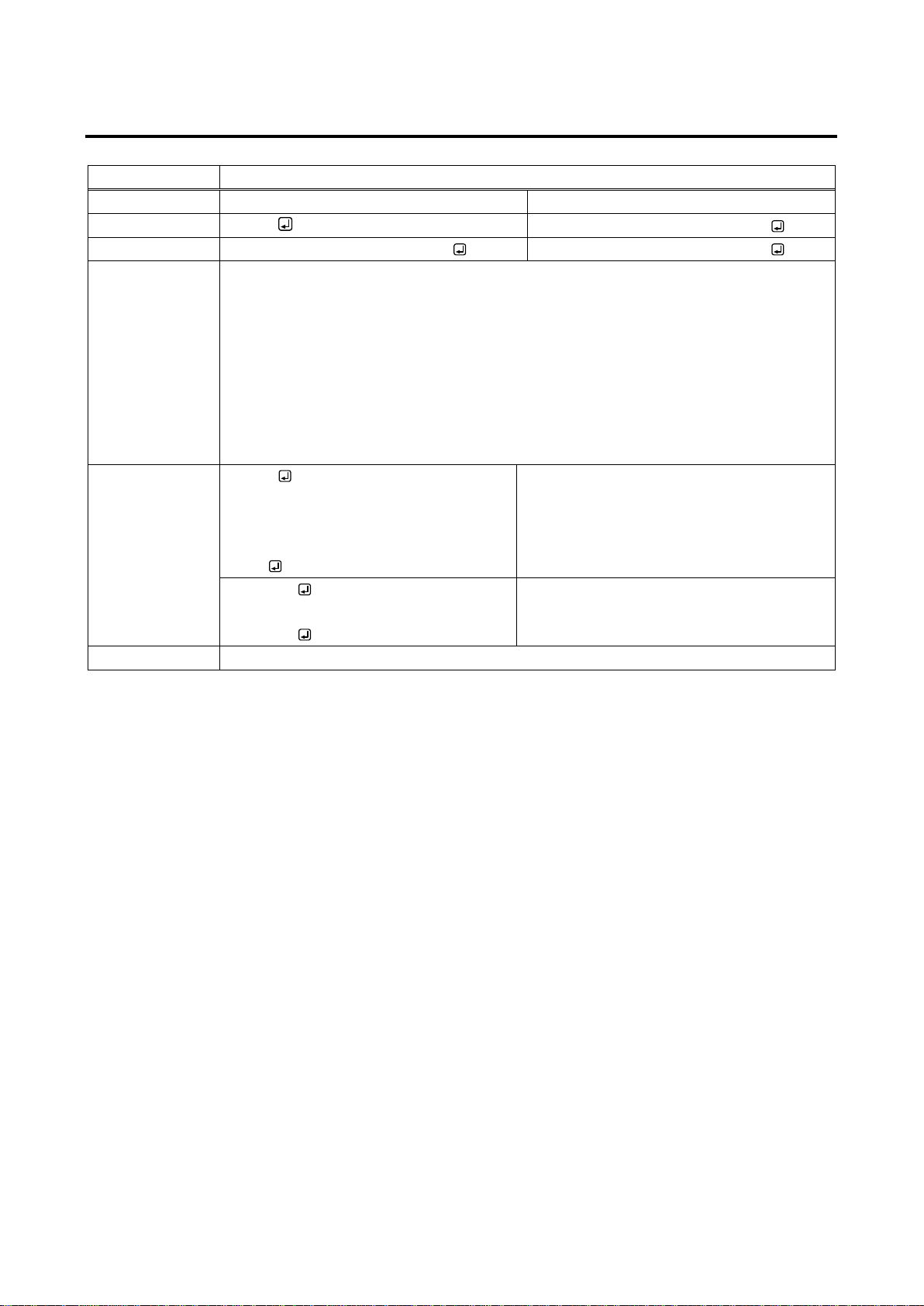
2.5.2 I/O channel selection
@GVA / @IOS
Switching I/O channels of FDX and MAU-1616 (optional) simultaneously
Function
Getting
Setting
Format
@GVA
@IOS,in_1,out_1 (,in_2,out_2・・・)
Return value
@GVA,v_1,a_1, ・・・ v_16,a_16
@IOS,in_1,out_1 (,in_2,out_2・・・)
Parameter
in_1 to in_16 : Input channels of FDX and MAU-1616
0 = OFF, 1 to 16 = INPUT1 to INPUT16
out_1 to out_16: Output channels of FDX and MAU-1616
0 = All outputs, 1 to 16 = OUTPUT1 to OUTPUT16
v_1 to v_16 : FDX output channel
a_1 to a_16 : MAU-1616 output channel
0 = OFF [Default], 1 to 16 = INPUT1 to INPUT16,
- 1 = Slot board is not mounted.
Example
@GVA
@GVA,1,1,2,2,3,3,4,4,5,5,6,6,7,7,8,8,9,
9,10,10,11,11,12,12,13,13,14,14,15,15,
16,16
Getting I/O channel statuses of FDX and
MAU-1616.
OUTPUT1 to 16 of FDX and MAU-1616:
INPUT1 to 16
@IOS,1,3
@IOS,1,3
Setting OUTPUT3 of FDX and MAU-1616 to
INPUT1.
Completed normally.
Remarks
-
FDX-16 Command Guide
21
Page 22
FDX-16 Command Guide
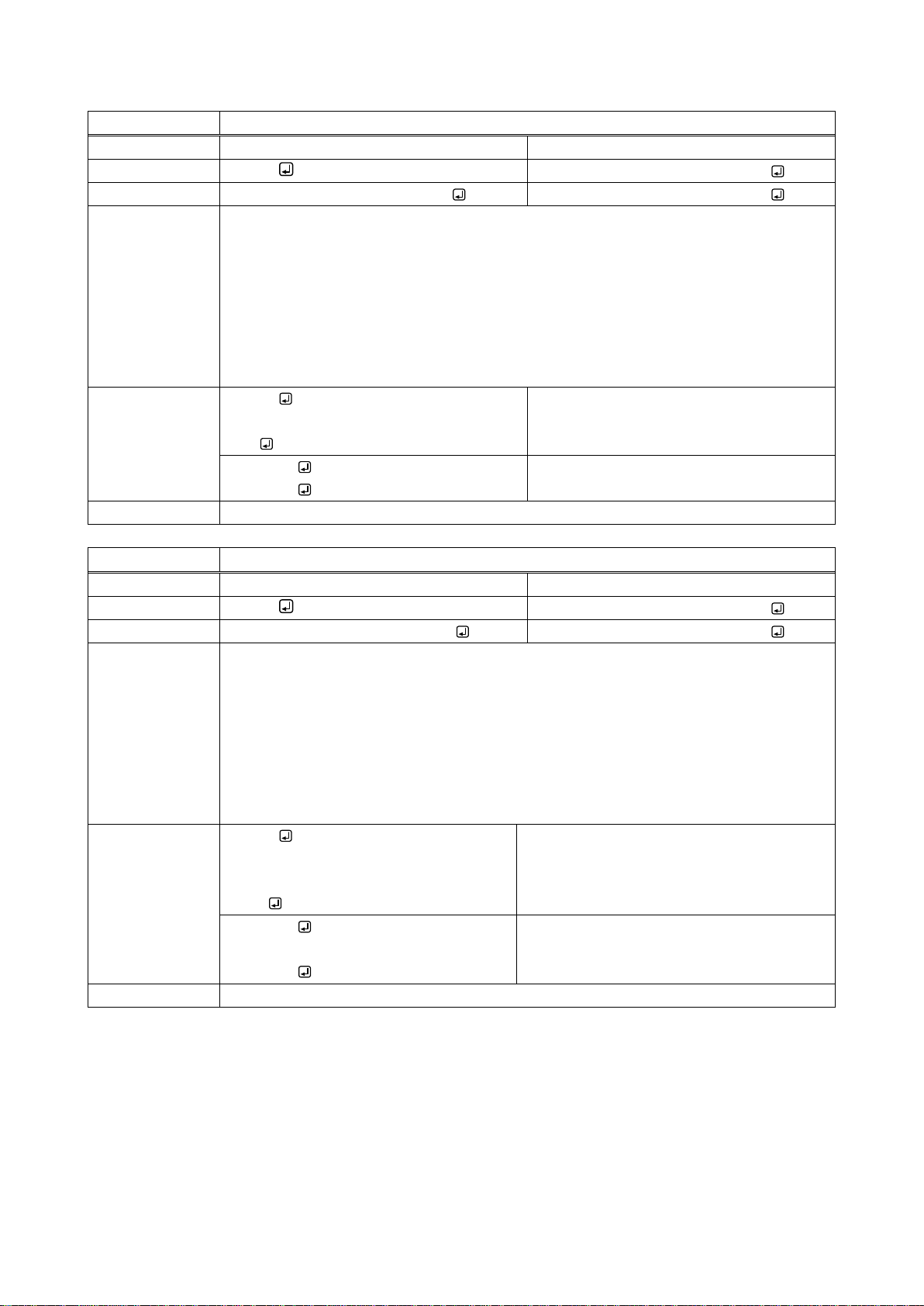
@GCP / @IOV
Switching only FDX I/O channels
Function
Getting
Setting
Format
@GCP
@IOV,in_1,out_1 (,in_2,out_2・・・)
Return value
@GCP,v_1,v_2, ・・・ v_15,v_16
@IOV,in_1,out_1 (,in_2,out_2・・・)
Parameter
in_1 to in_16 : FDX input channel
0 = OFF, 1 to 16 = INPUT1 to INPUT16
out_1 to out_16 : FDX output channel
0 = All outputs, 1 to 16 = OUTPUT1 to OUTPUT16
v_1 to v_16 : FDX output channel
0 = OFF [Default], 1 to 16 = INPUT1 to INPUT16,
- 1 = Slot board is not mounted.
Example
@GCP
@GCP,1,2,3,4,5,6,7,8,9,10,11,12,13,14,1
5,16
Getting I/O channel statuses of FDX.
OUTPUT1 to 16: INPUT1 to 16
@IOV,1,3
@IOV,1,3
Setting FDX OUTPUT3 to INPUT1.
Completed normally.
Remarks
- @GCA / @IOA
Switching only MAU-1616 I/O channels
Function
Getting
Setting
Format
@GCA
@IOA,in_1,out_1 (,in_2,out_2・・・)
Return value
@GCA,a_1,a_2, ・・・ a_15,a_16
@IOA,in_1,out_1 (,in_2,out_2・・・)
Parameter
in_1 to in_16 : MAU-1616 input channel
0 = OFF, 1 to 16 = INPUT1 to INPUT16
out_1 to out_16 : MAU-1616 output channel
0 = All outputs, 1 to 16 = OUTPUT1 to OUTPUT16
a_1 to a_16 : MAU-1616 output channel
0 = OFF [Default], 1 to 16 = INPUT1 to INPUT16,
- 1 = Slot board is not mounted.
Example
@GCA
@GCA,1,2,3,4,5,6,7,8,9,10,11,12,13,14,
15,16
Getting I/O channel statuses of MAU-1616.
OUTPUT1 to 16: INPUT1 to 16
@IOA,1,3
@IOA,1,3
Setting MAU-1616 OUTPUT3 to INPUT1.
Completed normally.
Remarks
-
22
Page 23
FDX-16 Command Guide
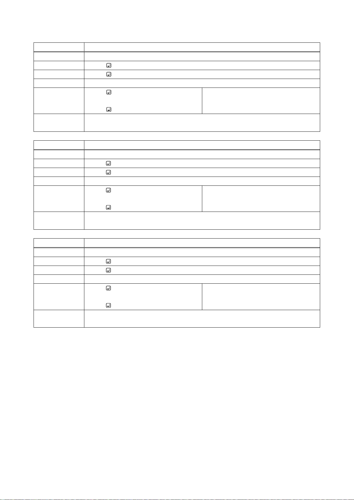
@SSC
Straight Switching* I/O of FDX and MAU-1616
Function
Setting
Format
@SSC
Return value
@SSC
Parameter
-
Example
@SSC
@SSC
Setting I/O of FDX and MAU-1616 to the
same number I/O.
Completed normally.
Remarks
*For example, OUTPUT1 is connected to INPUT1; OUTPUT2 is connected to INPUT2;
OUTPUT16 is connected to INPUT16.
@SSV
Straight Switching* I/O of FDX
Function
Setting
Format
@SSV
Return value
@SSV
Parameter
-
Example
@SSV
@SSV
Setting I/O of FDX to the same number
I/O.
Completed normally.
Remarks
*For example, OUTPUT1 is connected to INPUT1; OUTPUT2 is connected to INPUT2;
OUTPUT16 is connected to INPUT16.
@SSA
Straight Switching* I/O of MAU-1616
Function
Setting
Format
@SSA
Return value
@SSA
Parameter
-
Example
@SSA
@SSA
Setting I/O of MAU-1616 to the same
number I/O.
Completed normally.
Remarks
*For example, OUTPUT1 is connected to INPUT1; OUTPUT2 is connected to INPUT2;
OUTPUT16 is connected to INPUT16.
23
Page 24
FDX-16 Command Guide
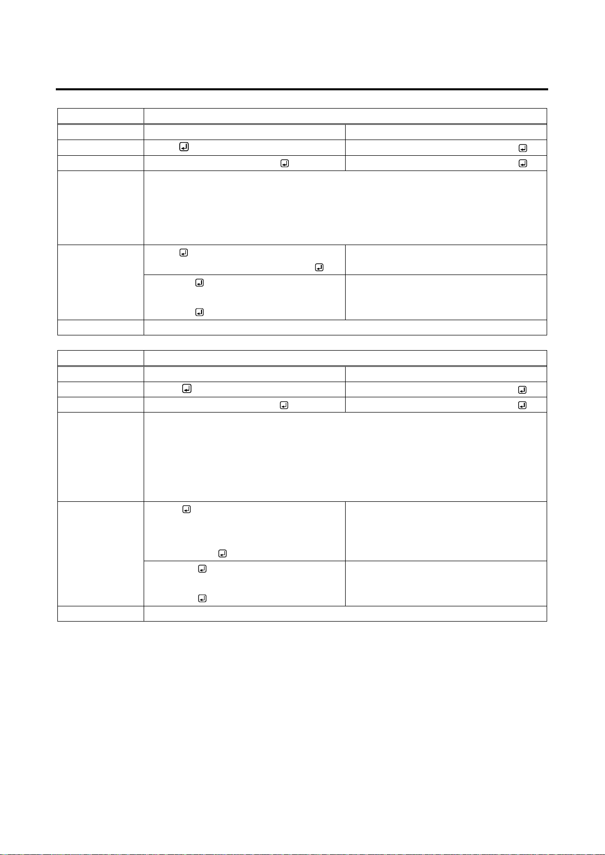
@GIQ / @SIQ
Input equalizer
Function
Getting
Setting
Format
@GIQ
@SIQ,in_1,level_1 (,in_2,level_2・・・)
Return value
@GIQ,level_1, ・・・ level_16
@SIQ,in_1,level_1 (,in_2,level_2・・・)
Parameter
in_1 to in_16 : Input channel
0 = All inputs, 1 to 16 = INPUT1 to INPUT16
level_1 to level_16 : Input equalizer of each input channel
0 = OFF, 1 = AUTO [Default], -1 = Digital input slot board is not mounted.
Example
@GIQ
@GIQ,1,1,1,1,1,1,1,1,1,1,1,1,1,1,1,1
Getting input equalizer status.
All input channels: AUTO
@SIQ,0,0
@SIQ,0,0
Setting input equalizers of All input
channels to “OFF”.
Completed normally.
Remarks
-
@GDT / @SDT
No-signal-input monitoring
Function
Getting
Setting
Format
@GDT
@SDT,in_1,time_1 (,in_2,time_2・・・)
Return value
@GDT,time_1, ・・・ time_16
@SDT,in_1,time_1 (,in_2,time_2・・・)
Parameter
in_1 to in_16 : Input channel
0 = All inputs, 1 to 16 = INPUT1 to INPUT16
time_1 to time_16 : Non-signal-input monitoring time of each input channel
0 = OFF, 3 to 15 = 3 to 15 seconds [Default]:10 seconds,
- 1 = Input slot board is not mounted.
Example
@GDT
@GDT,10,10,10,10,10,10,10,10,10,10,10,
10,10,10,10,10
Getting current settings of non-signal-input
monitoring time.
All input channels: 10 seconds
@SDT,0,4
@SDT,0,4
Setting non-signal-input monitoring time of
All input channel to 4 seconds.
Completed normally.
Remarks
-
2.5.3 Input setting
24
Page 25
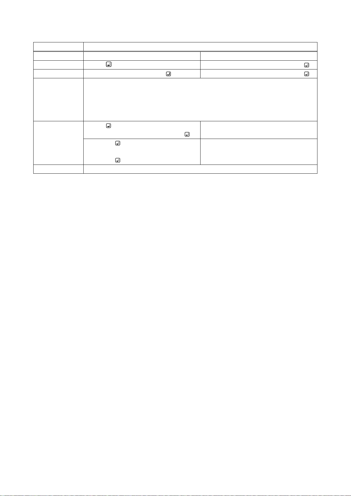
@GHE / @SHE
HDCP input enabled/disabled
Function
Getting
Setting
Format
@GHE
@SHE,in_1,hdcp_1 (,in_2,hdcp_2・・・)
Return value
@GHE,hdcp_1, ・・・ hdcp_16
@SHE,in_1,hdcp_1 (,in_2,hdcp_2・・・)
Parameter
in_1 to in_16 : Input channel
0 = All inputs, 1 to 16 = INPUT1 to INPUT16
hdcp_1 to hdcp_16 : HDCP input enabled/disabled of each input channel
0 = DISABLE, 1 = ENABLE [Default], -1 = Input slot board is not mounted.
Example
@GHE
@GHE,1,1,1,1,1,1,1,1,1,1,1,1,1,1,1,1
Getting HDCP input enabled/disabled.
All input channels: ENABLE
@SHE,0,0
@SHE,0,0
Setting All input channels of HDCP input
to DISABLE.
Completed normally.
Remarks
-
FDX-16 Command Guide
25
Page 26
FDX-16 Command Guide
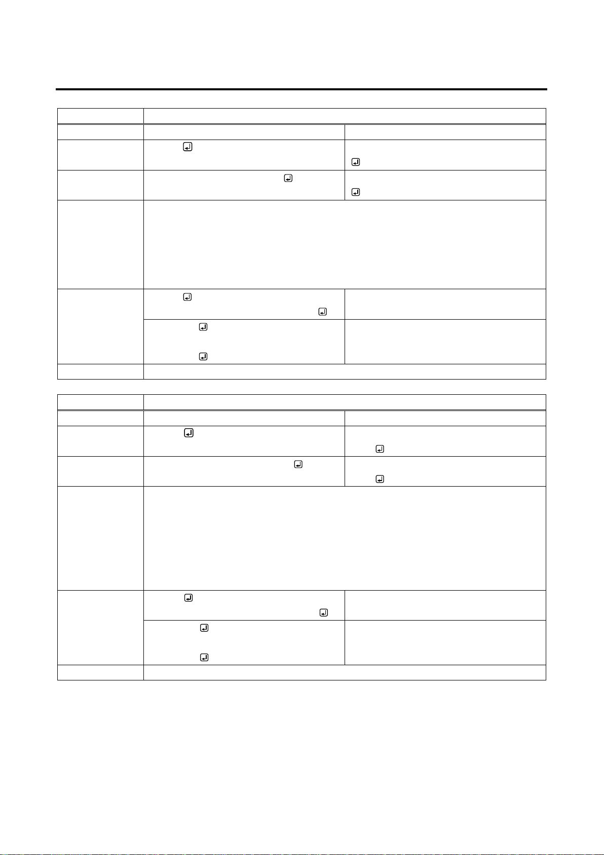
@GEQ / @SEQ
Output equalizer
Function
Getting
Setting
Format
@GEQ
@SEQ,out_1,level_1 (,out_2,level_2・・・)
Return value
@GEQ,level_1, ・・・ level_16
@SEQ,out_1,level_1 (,out_2,level_2・・・)
Parameter
out_1 to out_16: Output channel
0 = All outputs, 1 to 16 = OUTPUT1 to OUTPUT16
level_1 to level_16 : Output equalizer of each output channel
0 = OFF [Default], 1 = LOW, 2 = MEDIUM, 3 = HIGH,
- 2 = Digital output slot board is not mounted.
Example
@GEQ
@GEQ,0,0,0,0,0,0,0,0,0,0,0,0,0,0,0,0
Getting output equalizer status.
All output channels: OFF
@SEQ,0,0
@SEQ,0,0
Setting output equalizers of all output
channels to OFF.
Completed normally.
Remarks
-
@GDM / @SDM
Output mode
Function
Getting
Setting
Format
@GDM
@SDM,out_1,mode_1 (,out_2,mode_
2・・・)
Return value
@GDM,mode_1, ・・・ mode_16
@SDM,out_1,mode_1 (,out_2,mode_
2・・・)
Parameter
out_1 to out_16: Output channel
0 = All outputs, 1 to 16 = OUTPUT1 to OUTPUT16
mode_1 to mode_16 : Output mode of output channel
0 = AUTO MODE [Default], 1 = DVI MODE,
2 = HDMI YCbCr 4:4:4 MODE, 3 = HDMI YCbCr 4:2:2 MODE,
4 = HDMI RGB MODE, - 2 = Output slot board is not mounted.
Example
@GDM
@GDM,0,0,0,0,0,0,0,0,0,0,0,0,0,0,0,0
Getting output modes.
All output channels: AUTO MODE
@SDM,0,0
@SDM,0,0
Setting output mode of all output channels
to AUTO MODE.
Completed normally.
Remarks
-
2.5.4 Output setting
26
Page 27
FDX-16 Command Guide
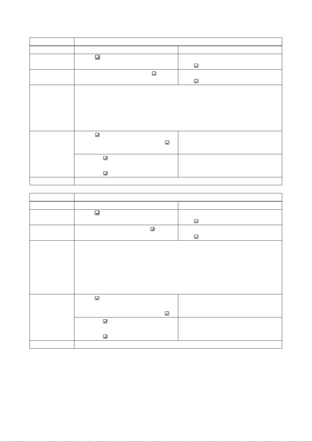
@GHM / @SHM
Forcibly HDMI signal output
Function
Getting
Setting
Format
@GHM
@SHM,out_1,mode_1 (,out_2,mode_
2・・・)
Return value
@GHM,mode_1, ・・・ mode_16
@SHM,out_1,mode_1 (,out_2,mode_
2・・・)
Parameter
out_1 to out_16 : Output channel
0 = All outputs, 1 to 16 = OUTPUT1 to OUTPUT16
mode_1 to mode_16 : Forcibly HDMI signal output of each output channel
0 = OFF [Default], 1 = Forcibly HDMI signal output at EDID loading error,
2 = HDMI signal output at all times, - 2 = Output slot board is not mounted.
Example
@GHM
@GHM,0,0,0,0,0,0,0,0,0,0,0,0,0,0,0,0
Getting statuses of forcibly HDMI signal
output.
All output channel: OFF
@SHM,0,0
@SHM,0,0
Setting forcibly HDMI signal output of all
output channels to OFF.
Completed normally.
Remarks
-
@GMK / @SMK
Time for ignoring video output request signals
Function
Getting
Setting
Format
@GMK
@SMK,out_1,mask_1 (,out_2,mask_
2・・・)
Return value
@GMK,mask_1, ・・・ mask_16
@SMK,out_1,mask_1 (,out_2,mask_
2・・・)
Parameter
out_1 to out_16: Output channel
0 = All outputs, 1 to 16 = OUTPUT1 to OUTPUT16
mask_1 to mask_16 : Time for ignoring video output request signals of each output
channel
1 = OFF [Default], 2 to 15 = 2 to 15 seconds, -2 = Output slot board is not
mounted.
Example
@GMK
@GMK,1,1,1,1,1,1,1,1,1,1,1,1,1,1,1,1
Getting times for ignoring video output
request signals.
All output channel: OFF
@SMK,0,1
@SMK,0,1
Setting time for ignoring video output
request signals of all output channel: OFF.
Completed normally.
Remarks
-
27
Page 28
FDX-16 Command Guide
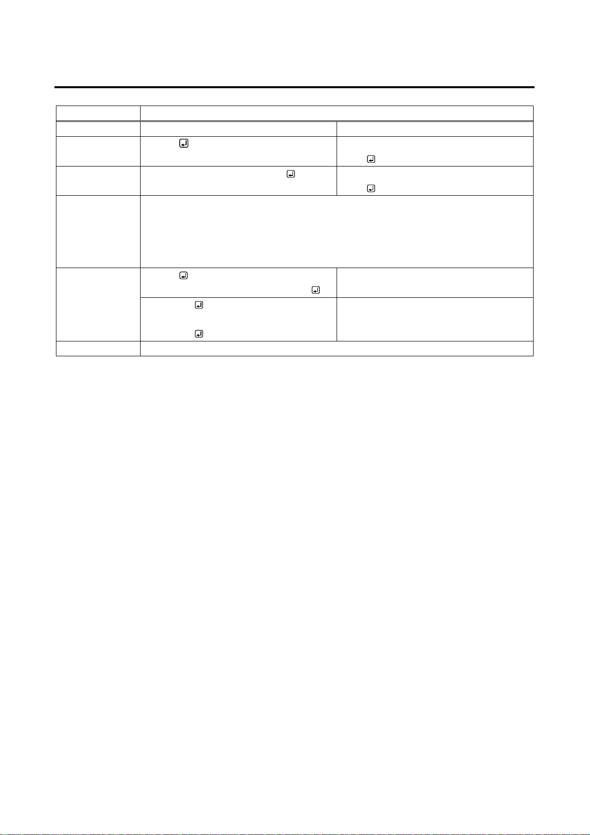
@GDO / @SDO
Digital audio output
Function
Getting
Setting
Format
@GDO
@SDO,out_1,mode_1 (,out_2,mode_
2・・・)
Return value
@GDO,mode_1, ・・・ mode_16
@SDO,out_1,mode_1 (,out_2,mode_
2・・・)
Parameter
out_1 to out_16 : Output channel
0 = All outputs, 1 to 16 = OUTPUT1 to OUTPUT16
mode_1 to mode_16 : Digital audio output of each output channel
0 = Stop output, 1 = Audio output [Default], -2 = Output slot board is not mounted.
Example
@GDO
@GDO,1,1,1,1,1,1,1,1,1,1,1,1,1,1,1,1
Getting digital audio output statuses.
All output channel: Digital audio output
@SDO,0,0
@SDO,0,0
Setting digital audio output of all output
channels to Stop.
Completed normally.
Remarks
-
2.5.5 Audio setting
28
Page 29
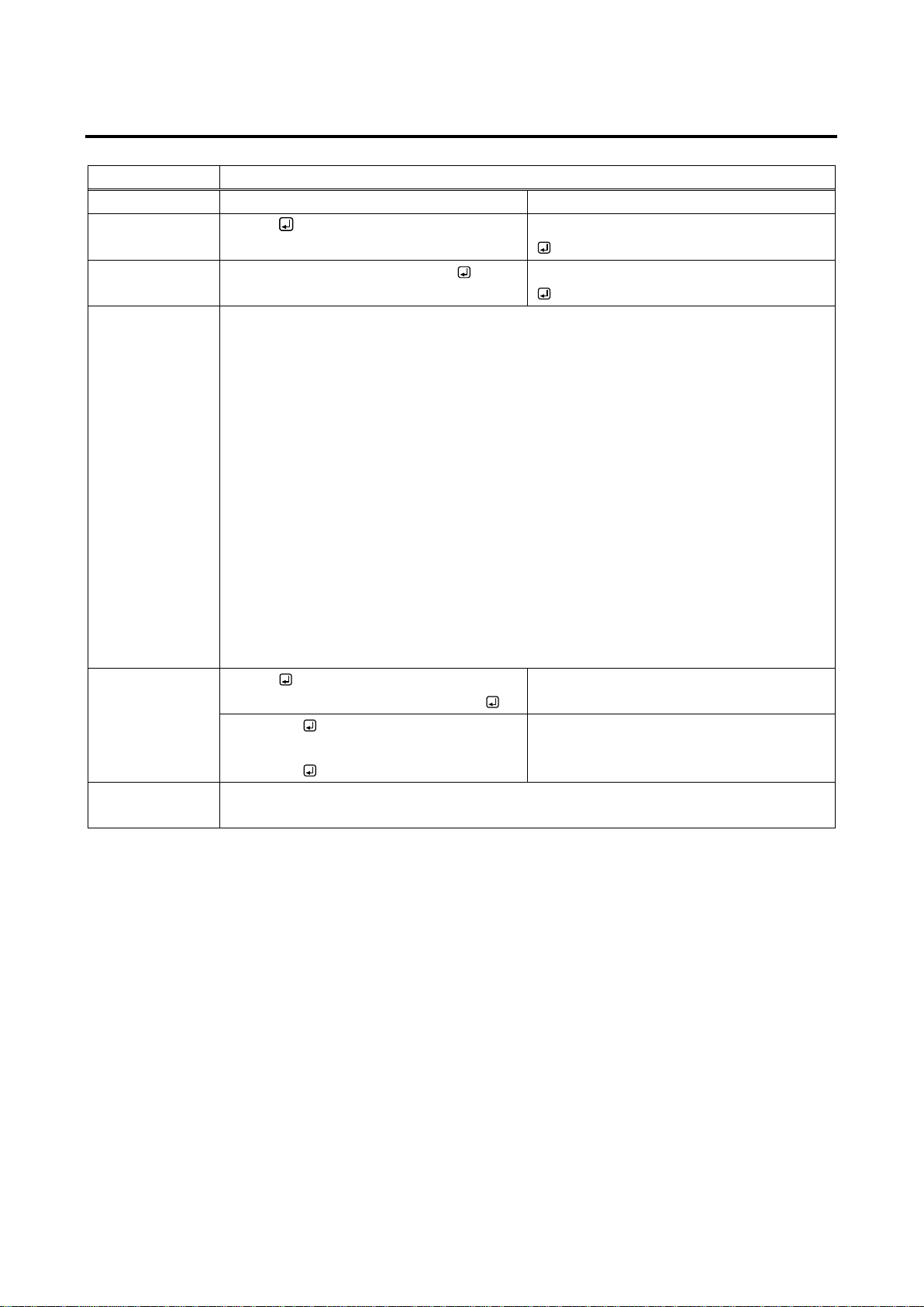
2.5.6 EDID setting
@GED / @SED
EDID resolution
Function
Getting
Setting
Format
@GED
@SED,in_1,format_1 (,in_2,format_2・・・)
Return value
@GED,format_1, ・・・ format_16
@SED,in_1,format_1 (,in_2,format_2・・・)
Parameter
in_1 to in_16 : Input channel
0 = All inputs, 1 to 16 = INPUT1 to INPUT16
format_1 to format_16 : EDID of input channel
0 = External EDID, 1 to 4 = Copied EDID 1 to 4,
5 = 1080p (59.94 / 60) [Default], 6 = 720p,
7 = 1080i, 8 = 1080p (24 / 25 / 30 / 50),
9 = SVGA (800×600), 10 = XGA (1024×768),
11 = VESA720 (1280×720), 12 = WXGA (1280×768),
13 = WXGA (1280×800), 14 = Quad-VGA (1280×960),
15 = SXGA (1280×1024), 16 = WXGA (1360 / 1366×768),
17 = SXGA+ (1400×1050), 18 = WXGA+ (1440×900),
19 = WXGA++ (1600×900), 20 = UXGA (1600×1200),
21 = WSXGA+ (1680×1050), 22 = VESA1080 (1920×1080),
23 = WUXGA (1920×1200), 24 = QWXGA (2048×1152),
- 1 = Input slot board is not mounted.
Example
@GED
@GED,5,5,5,5,5,5,5,5,5,5,5,5,5,5,5,5
Getting EDID resolutions.
All input channel: 1080p (59.94 / 60)
@SED,0,0
@SED,0,0
Setting EDID of All input channels to
External EDID.
Completed normally.
Remarks
To select 1 to 4 for EDID of each input channel, copy EDID of the sink device using
@RME command beforehand.
FDX-16 Command Guide
29
Page 30
FDX-16 Command Guide
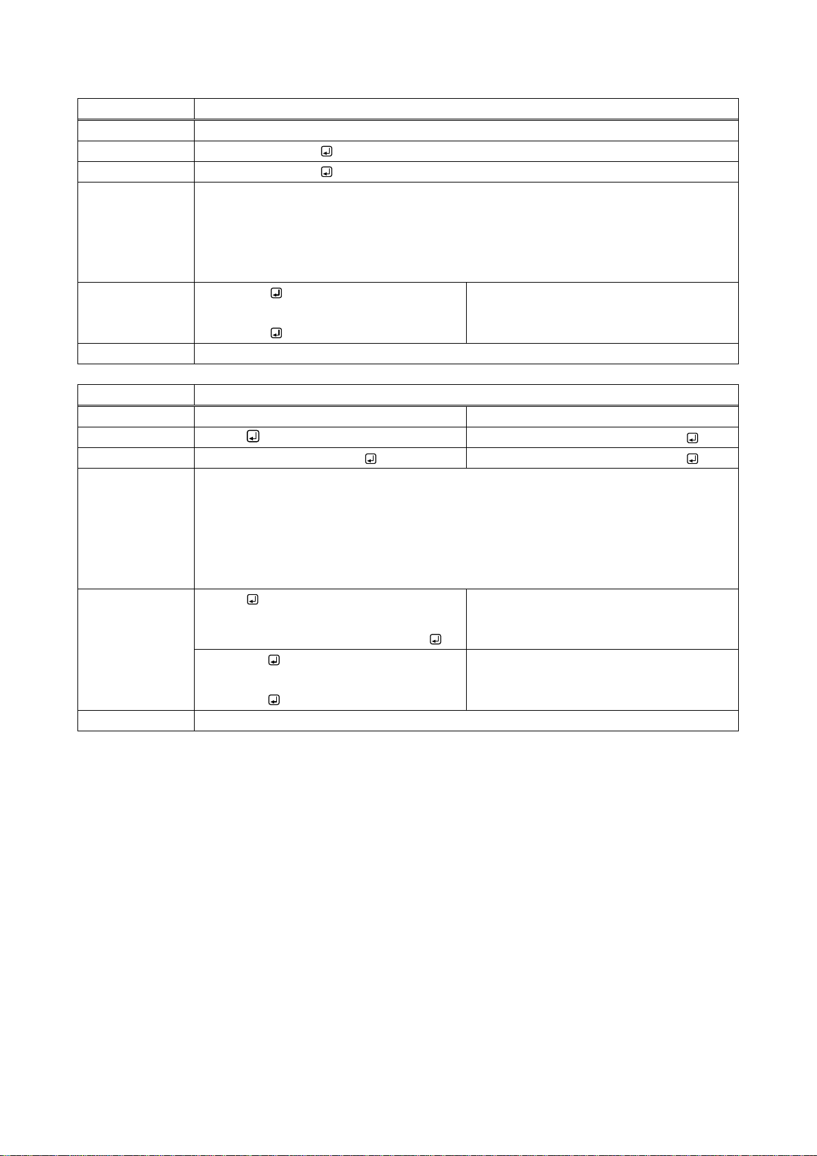
@RME
Copying EDID
Function
Setting
Format
@RME,out,number
Return value
@RME,out,number
Parameter
out :Channel to be loaded
1 to 16 = OUTPUT1 to OUTPUT16
number : Destination memory number
1 to 4 = Memory 1 to 4
Example
@RME,1,1
@RME,1,1
Setting EDID of the sink device connected
to OUTPUT1 to Memory 1.
Completed normally.
Remarks
-
@GEC / @SEC
EDID loading channel
Function
Getting
Setting
Format
@GEC
@SEC,in_1,out_1 (,in_2,out_2・・・)
Return value
@GEC,out_1, ・・・ out_16
@SEC,in_1,out_1 (,in_2,out_2・・・)
Parameter
in_1 to in_16 : Input channel
0 = All inputs, 1 to 16 = INPUT1 to INPUT16
out_1 to out_16 : EDID loading channel of each input channel
1 to 16 = OUTPUT1 to OUTPUT16,
-1 = Input slot board is not mounted., -2 = Output slot board is not mounted.
Example
@GEC
@GEC,1,1,1,1,1,1,1,1,1,1,1,1,1,1,1,1
Getting statuses of EDID loading channel.
All input channels: From OUTPUT1.
@SEC,0,1
@SEC,0,1
Setting EDID loading channels of all input
channels to OUTPUT1.
Completed normally.
Remarks
This command is available only if “0” (External EDID) is selected for EDID resolution.
30
Page 31
FDX-16 Command Guide
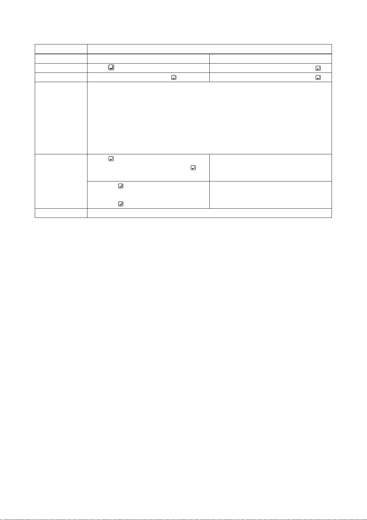
@GDI / @SDI
Deep Color input
Function
Getting
Setting
Format
@GDI
@SDI,in_1,color_1 (,in_2,color_2・・・)
Return value
@GDI,color_1, ・・・ color_16
@SDI,in_1,color_1 (,in_2,color_2・・・)
Parameter
in_1 to in_16: Input channel
0 = All inputs, 1 to 16 = INPUT1 to INPUT16
color_1 to color_16 : Deep Color of each input channel
0 = 24 bit / pixel ( 8 bit / component) [Default],
1 = 30 bit / pixel (10 bit / component),
2 = 36 bit / pixel (12 bit / component),
- 1 = Input slot board is not mounted.
Example
@GDI
@GDI,0,0,0,0,0,0,0,0,0,0,0,0,0,0,0,0
Getting Deep Color statuses.
All input channels: 24 bit/pixel (8 bit/
component).
@SDI,0,0
@SDI,0,0
Setting Deep Color of all input channels to
24 bit/pixel (8 bit/component).
Completed normally.
Remarks
-
31
Page 32
FDX-16 Command Guide
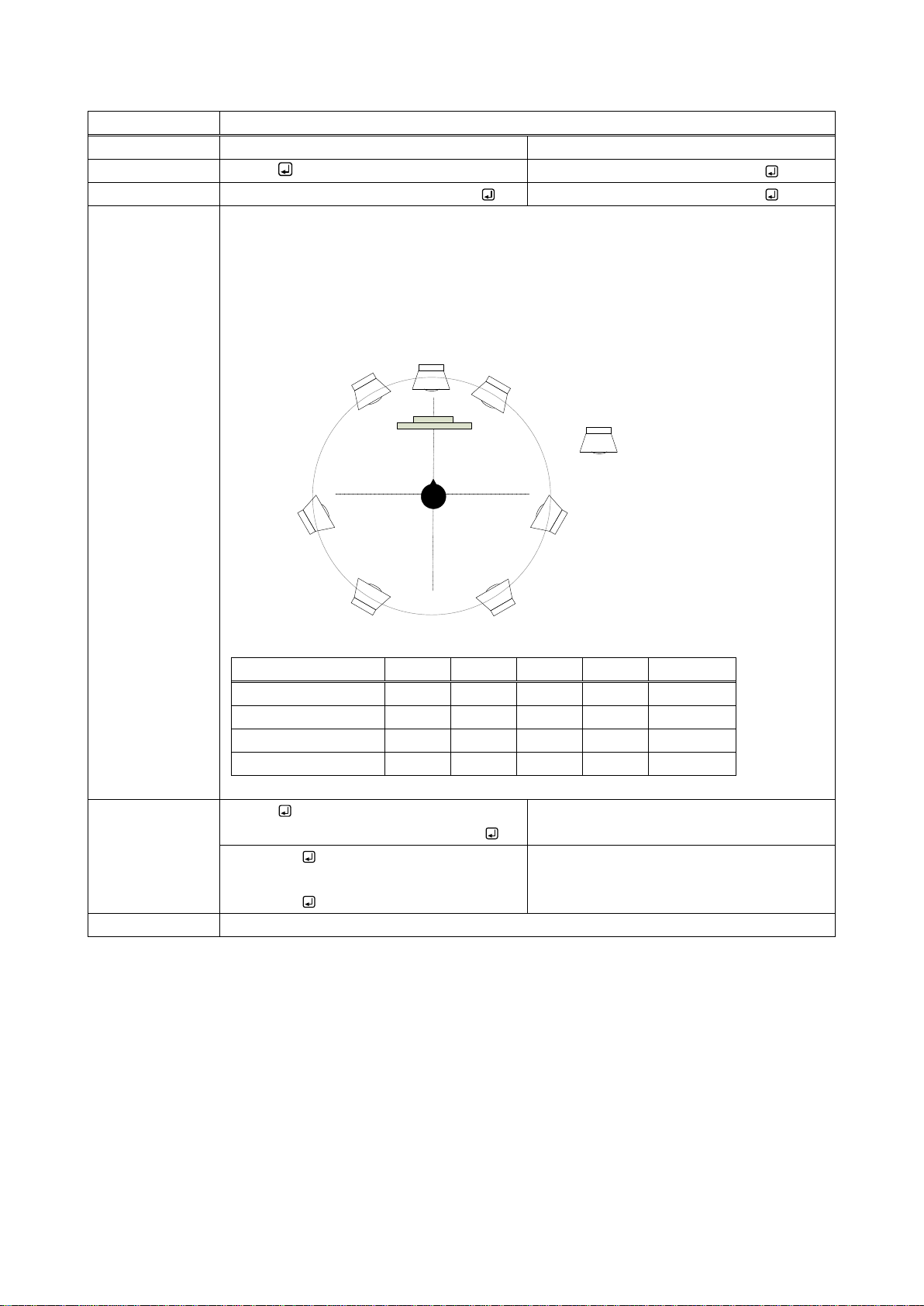
@GSP / @SSP
The number of audio channels
Function
Getting
Setting
Format
@GSP
@SSP,in_1,ch_1 (,in_2,ch_2・・・)
Return value
@GSP,ch_1,ch_2 ・・・ ch_15,ch_16
@SSP,in_1,ch_1 (,in_2,ch_2・・・)
Parameter
in_1 to in_16 : Input channel
0 = All inputs, 1 to 16 = INPUT1 to INPUT16
ch_1 to ch_16 : The number of audio channels of each input channel
0 = 2 channels [Default], 1 = 2.1 channels, 2 = 5.1 channels,
3 = 7.1 channels, - 1 = Input slot board is not mounted.
The number of channels
FL/FR
LFE
FC
RL/RR
RLC/RRC
2 channel
ON
OFF
OFF
OFF
OFF
2.1 channel
ON
ON
OFF
OFF
OFF
5.1 channel
ON
ON
ON
ON
OFF
7.1 channel
ON
ON
ON
ON
ON
Example
@GSP
@GSP,0,0,0,0,0,0,0,0,0,0,0,0,0,0,0,0
Getting the number of audio channels.
All input channels: 2 channels
@SSP,0,0
@SSP,0,0
Setting the number of audio channels of all
input channels: 2 channels
Completed normally.
Remarks
-
RL
RLC RRC
RR
FR
FC
FL
LFE
FL : Front Left
FC : Front Center
FR : Front Right
RL : Rear Left
RR : Rear Right
RLC
Rear Left Center
RRC
Rear Right Center
Low Frequency Effect
LFE
:
:
:
32
Page 33
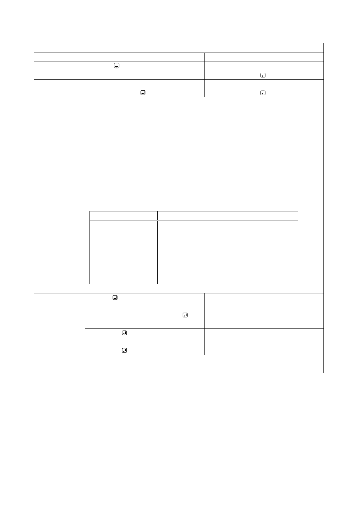
FDX-16 Command Guide
@GAF / @SAF
Audio format
Function
Getting
Setting
Format
@GAF,in
@SAF,in,format_1,frequency_1 (,format_
2, frequency_2・・・)
Return value
@GAF,in,format_1,frequency_1, ・・・ for
mat_7,frequency_7
@SAF,in,format_1,frequency_1 (,format_
2, frequency_2・・・)
Parameter
in : Input channel
1 to 16 = INPUT1 to INPUT16
format_1 to format_7 : Audio format
0 = Linear PCM, 1 = AC-3 / Dolby Digital, 2 = AAC,
3 = Dolby Digital+, 4 = DTS, 5 = DTS-HD,
6 = Dolby TrueHD
frequency_1 to frequency_7 : Maximum sampling frequency
0 = OFF (No output), 1 = 32 kHz, 2 = 44.1 kHz,
3 = 48 kHz, 4 = 88.2 kHz, 5 = 96 kHz,
6 = 176.4 kHz, 7 = 192 kHz, - 1 = Input slot board is not mounted.
Audio format
Sampling frequency (kHz)
Linear PCM
32 / 44.1 / 48 [Default] / 88.2 / 96 / 192
AC-3 / Dolby Digital
OFF [Default] / 32 / 44.1 / 48
AAC
OFF [Default] / 32 / 44.1 / 48 / 88.2 / 96
Dolby Digital +
OFF [Default] / 32 / 44.1 / 48
DTS
OFF [Default] / 32 / 44.1 / 48 / 96
DTS-HD
OFF [Default] / 44.1 / 48 / 88.2 / 96 / 176.4 / 192
Dolby TrueHD
OFF [Default] / 44.1 / 48 / 88.2 / 96 / 176.4 / 192
Example
@GAF,1
@GAF,1,0,3,1,0,2,0,3,0,4,0,5,0,6,0
Getting audio format status of INPUT1
channel.
Maximum sampling frequency of linear
PCM: 48 kHz; other audio format: OFF
@SAF,1,0,7
@SAF,1,0,7
Setting the maximum sampling frequency
of linear PCM of INPUT1 to up to 192 kHz.
Completed normally.
Remarks
The available maximum sampling frequency depends on the audio format.
Linear PCM output cannot be disabled.
33
Page 34
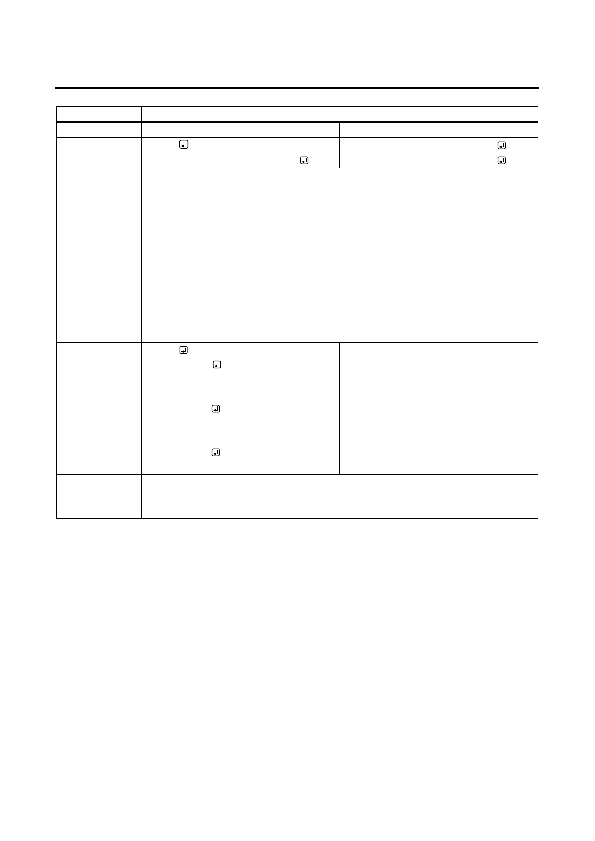
FDX-16 Command Guide
@GCT / @SCT
RS-232C communication
Function
Getting
Setting
Format
@GCT
@SCT,baudrate,length,parity,stop
Return value
@GCT,baudrate,length,parity,stop
@SCT,baudrate,length,parity,stop
Parameter
baudrate: Communication speed
0 = 4800 bps, 1 = 9600 bps [Default], 2 = 14400 bps,
3 = 19200 bps, 4 = 38400 bps
length: Data bit length
0 = 7 bit, 1 = 8 bit [Default]
parity: Parity check
0 = None [Default], 1 = Odd, 2 = Even
stop: stop bit
0 = 1 bit [Default], 1 = 2 bit
Example
@GCT
@GCT,1,1,0,0
Getting RS-232C communication setting
status.
Baud rate: 9600 bps; data bit length: 8 bit;
parity check: none; stop bit: 1 bit.
@SCT,1,1,0,0
@SCT,1,1,0,0
Setting baud rate, data bit, parity check,
and stop bit of RS-232C communication to
9600 bps,8 bit, none, and 1 bit,
respectively.
Completed normally.
Remarks
Once RS-232C communication setting is changed, the communication may be
disabled. Change the environmental settings of communication based on the FDX
settings.
2.5.7 RS-232C communication
34
Page 35
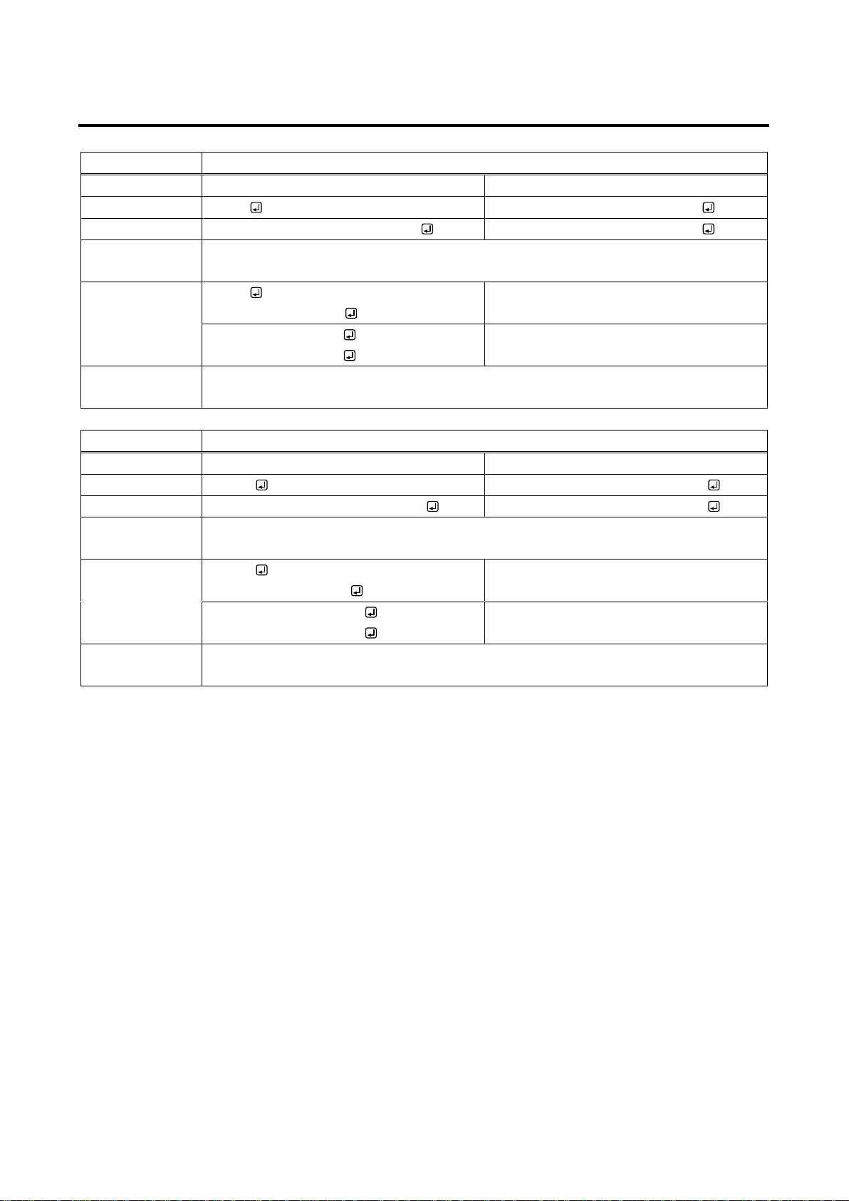
2.5.8 LAN communication
@GIP / @SIP
IP address
Function
Getting
Setting
Format
@GIP
@SIP,unit_1,unit_2,unit_3,unit_4
Return value
@GIP,unit_1,unit_2,unit_3,unit_4
@SIP,unit_1,unit_2,unit_3,unit_4
Parameter
unit_1 to unit_4 : Upper bit of the IP address to lower bit of the IP address
0 to 255 = 8 bit (Decimal notation) [Default]192.168.1.199
Example
@GIP
@GIP,192,168,1,200
Getting IP address.
192.168.1.200
@SIP,192,169,1,200
@SIP,192,169,1,200
Setting IP address to 192.168.1.200.
Completed normally.
Remarks
Once LAN setting is changed, the communication may be disabled. Change the
environmental settings of communication based on the FDX settings.
@GSB / @SSB
Subnet mask
Function
Getting
Setting
Format
@GSB
@SSB,unit_1,unit_2,unit_3,unit_4
Return value
@GSB,unit_1,unit_2,unit_3,unit_4
@SSB,unit_1,unit_2,unit_3,unit_4
Parameter
unit_1 to unit_4 : Upper bit of the subnet mask to lower bit of the subnet mask
0 to 255 = 8 bit (Decimal notation) [Default] 255.255.255.0
Example
@GSB
@GSB,255,255,255,0
Getting subnet mask.
255.255.255.0
@SSB,255,255,255,254
@SSB,255,255,255,254
Setting subnet mask to 255.255.255.254.
Completed normally.
Remarks
Once LAN setting is changed, the communication may be disabled. Change the
environmental settings of communication based on the FDX settings.
FDX-16 Command Guide
35
Page 36
FDX-16 Command Guide
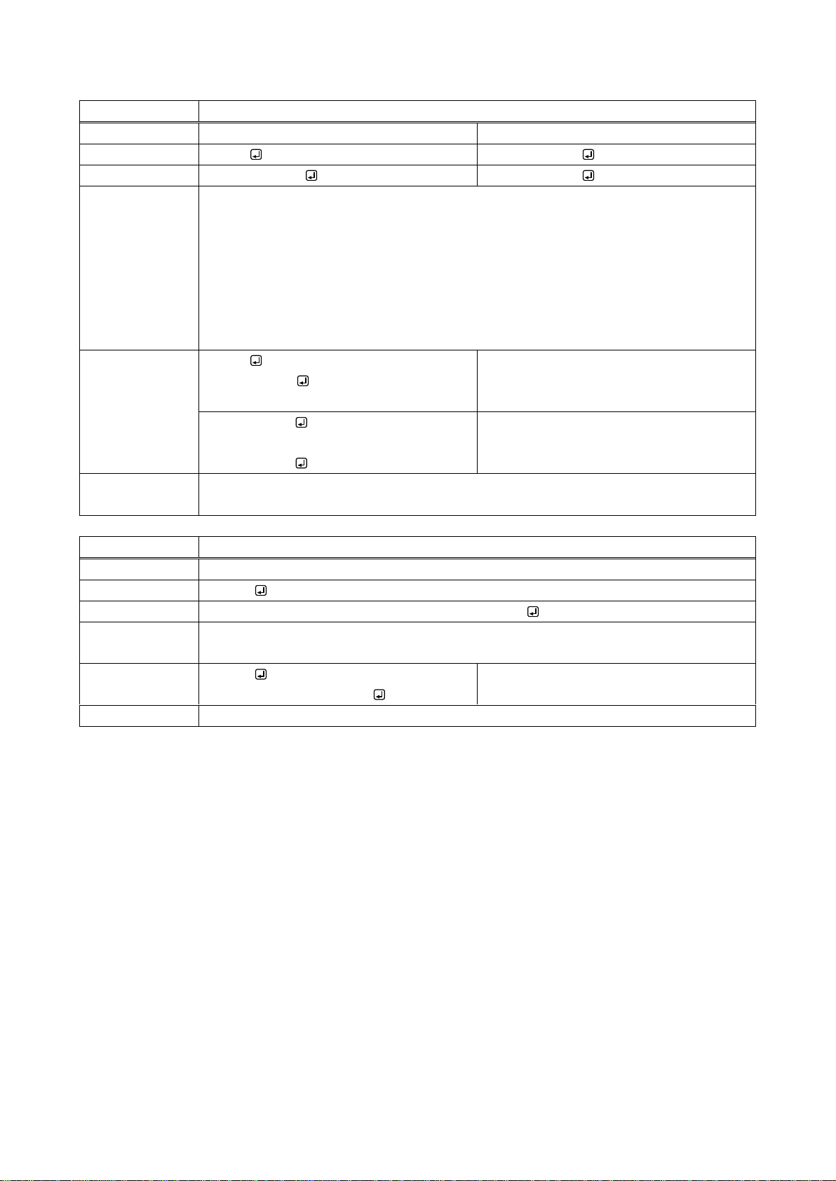
@GLP / @SLP
TCP port number
Function
Getting
Setting
Format
@GLP
@SLP,port,add
Return value
@GLP,port,add
@SLP,port,add
Parameter
port : Port number
1100 [Default], 6000 to 6999
add : 8 connection setting
0 = 8 connection setting OFF [Default]
(WEB browser 4 connections/communication command control 4 connections),
1 = 8 connection setting ON
(Communication command control 8 connections)
Example
@GLP
@GLP,1100,0
Getting TCP port number.
Port number: 1100; 8 connection setting:
OFF
@SLP,1100,0
@SLP,1100,0
Setting port number and 8 connection
setting to 1100 and OFF, respectively.
Completed normally.
Remarks
Once LAN setting is changed, the communication may be disabled. Change the
environmental settings of communication based on the FDX settings.
@GMC
MAC address
Function
Getting
Format
@GMC
Return value
@GMC,unit_1, unit_2, unit_3, unit_4, unit_5, unit_6
Parameter
unit_1 to unit_6 : Upper bit of the MAC address to lower bit of the MAC address
00 to FF = 8 bit (in hex)
Example
@GMC
@GMC,00,08,E5,59,00,01
Getting MAC address.
The MAC is displayed.
Remarks
-
36
Page 37
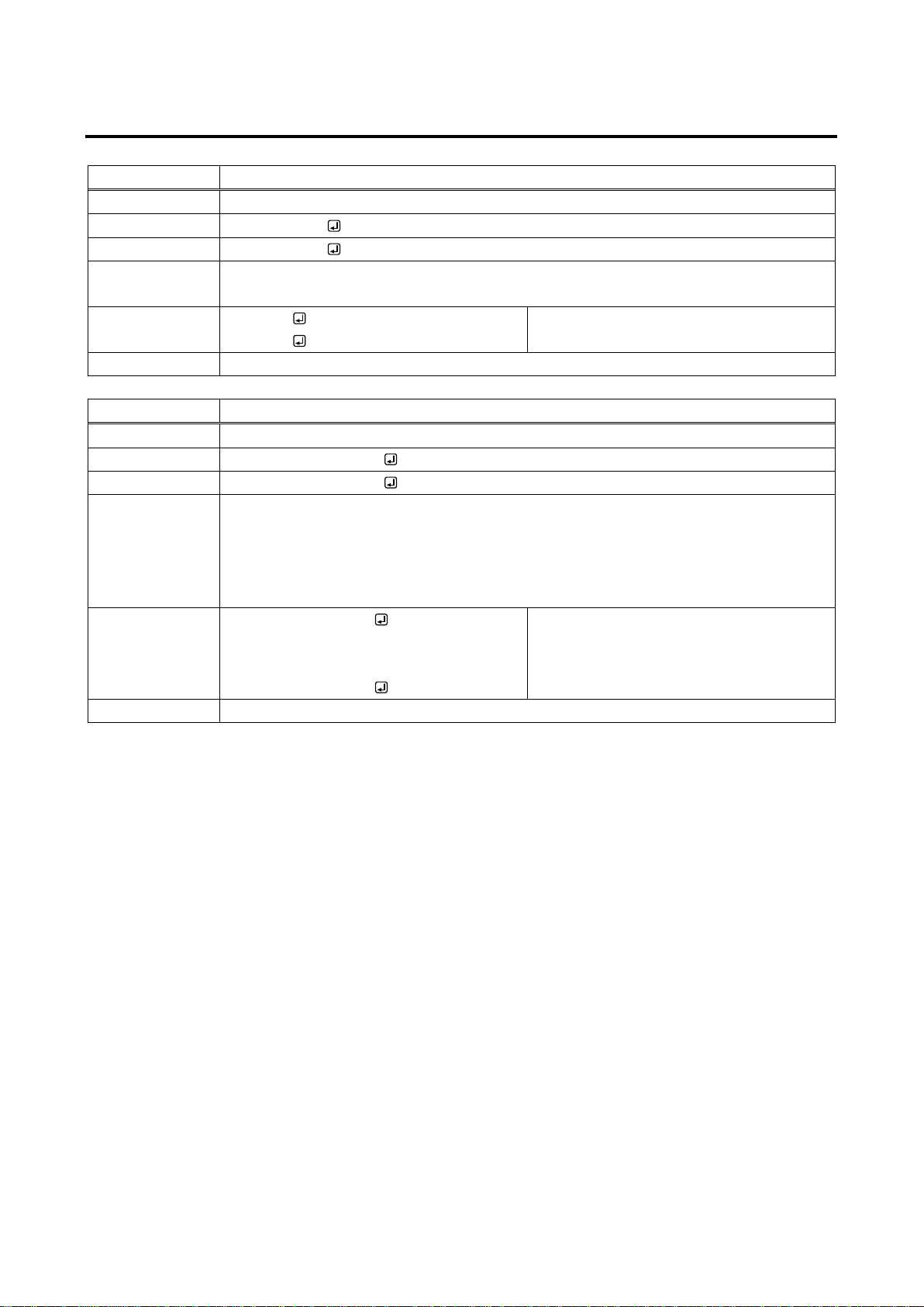
2.5.9 Preset memory
@RPM
Loading preset memory
Function
Setting
Format
@RPM,preset
Return value
@RPM,preset
Parameter
Preset: Preset memory
1 to 32 = Preset memory number
Example
@RPM,1
@RPM,1
Loading preset memory 1.
Completed normally.
Remarks
-
@SPM
Saving preset memory – [D] Delete
Function
Setting
Format
@SPM,preset (,name)
Return value
@SPM,preset (,name)
Parameter
preset: Preset memory
1 to 32 = Preset memory number
name: Memory name
Up to 10 characters from 0x20 to 0x7D of ASCII code
Example
@SPM,1,MEMORY1
@SPM,1,MEMORY1
Saving the current I/O channel settings in
Preset memory 1 with the name of
“MEMORY1”.
Completed normally.
Remarks
You can skip the naming process. If you skip it, the current name will be used.
FDX-16 Command Guide
37
Page 38
FDX-16 Command Guide
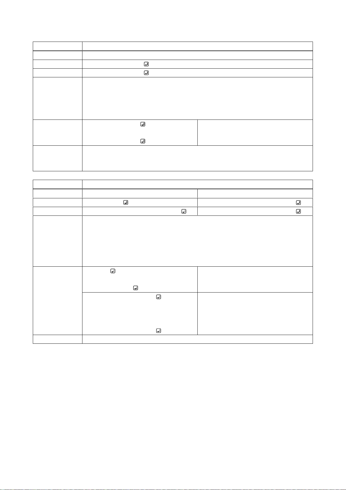
@SEM
Saving preset memory – [C] Continue
Function
Setting
Format
@SEM,preset (,name)
Return value
@SEM,preset (,name)
Parameter
preset: Preset memory
1 to 32 = Preset memory number
name: Memory name
Up to 10 characters from 0x20 to 0x7D of ASCII code.
Example
@SEM,1,MEMORY1
@SEM,1,MEMORY1
Saving I/O status in Preset memory 1 with
the name of “MEMORY1”.
Completed normally.
Remarks
You can skip the naming process. If you skip it, the current name will be used.
For preset setting, if Not control channel setting is included, the output channel setting is
not saved.
@GCM / @ECM
Editing preset memory
Function
Getting
Setting
Format
@GCM,preset
@ECM,preset,v_1,a_1・・・v_16,a_16
Return value
@GCM,preset,v_1,a_1・・・v_16,a_16
@ECM,preset,v_1,a_1・・・v_16,a_16
Parameter
preset : Preset memory
1 to 32 = Preset memory number
v_1 to v_16 : FDX output channel
a_1 to a_16 : MAU-1616 output channel
- 1 = Not control [Default], 0 = OFF, 1 to 16 = INPUT1 to INPUT16
Example
@GCM,1
@GCM,1,-1, -1, -1, -1, -1, -1, -1, -1, -1, -1,
-1, -1, -1, -1, -1, -1
Getting statuses of Preset memory 1.
All output channels: Not controlled
@ECM,1,1,1・・・15,15,-1,-1
@ECM,1,1,1・・・15,15,-1,-1
For Preset memory 1, setting OUTPUT1
to OUTPUT15 to the same number I/O
channels; setting OUTPUT16 to not be
controlled.
Completed normally.
Remarks
-
38
Page 39
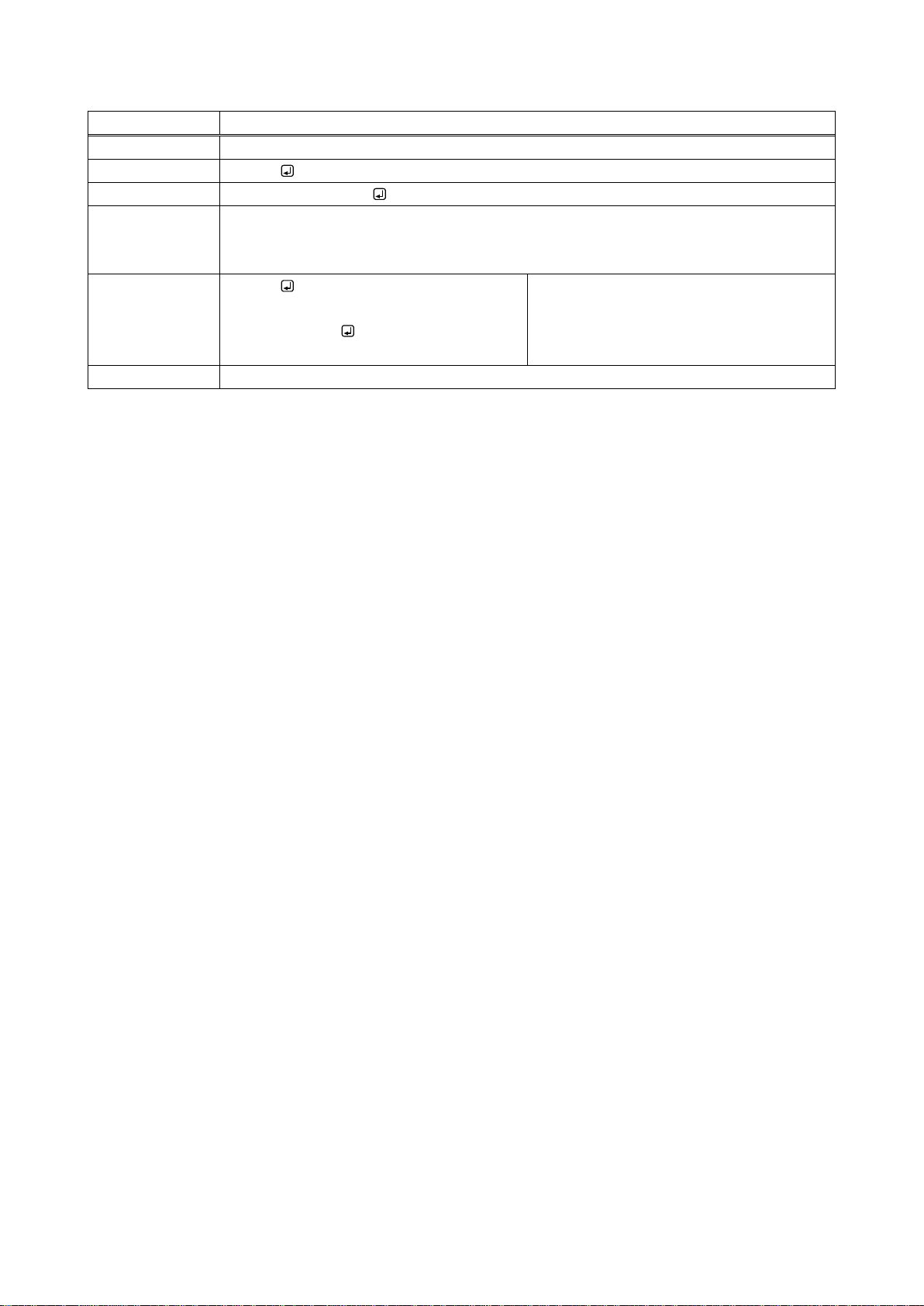
@GPM
Preset memory number matching current I/O channel status
Function
Getting
Format
@GPM
Return value
@GPM, video, audio
Parameter
video : Preset memory number matching FDX I/O status
audio : Preset memory number matching MAU-3232 channel status
000 = None, 001 to 032 = preset memory number
Example
@GPM
@GPM,000,000
Getting reset memory number matching
FDX I/O status
The preset memory number will be
displayed.
Remarks
If several memory numbers are matched, the smaller number will be returned.
FDX-16 Command Guide
39
Page 40
FDX-16 Command Guide
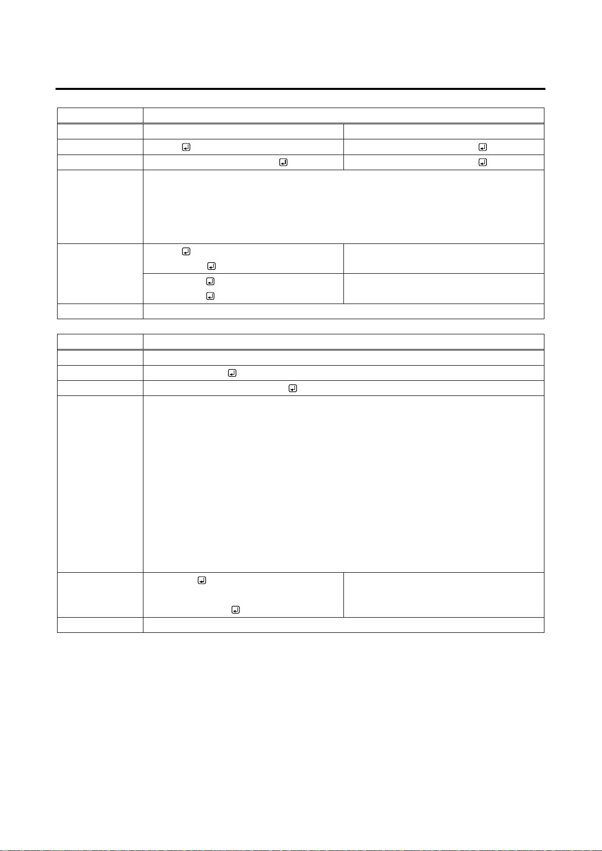
@GLM / @SLM
Key lock
Function
Getting
Setting
Format
@GLM
@SLM,channel,menu,preset
Return value
@GLM,channel,menu,preset
@SLM,channel,menu,preset
Parameter
channel : I/O output channel selection keys/channel switching direction keys/
switching mode selection keys
menu : Menu operation keys
preset : Preset memory loading keys
0 = Key lock OFF [Default], 1 = Key lock ON
Example
@GLM
@GLM,0,0,0
Getting key lock statuses.
All keys: OFF
@SLM,1,1,1
@SLM,1,1,1
Setting key lock of all keys to ON.
Completed normally.
Remarks
-
@GST
Slot board status
Function
Getting
Format
@GST,board,slot
Return value
@GST,board,slot,temp,voltage
Parameter
board: Slot board selection
0 = Input slot board, 1 = Output slot board
slot: Slot board place
1 to 4 = slot board1 to slot board4
temp: Temperature
The value of temperature x 100, - 1 = slot board is not mounted.
e.g.)38.75℃: 3875
voltage :
0 = Normal, 1 = Abnormal, - 1 = Slot board is not mounted.
Example
@GST,0,1
@GST,0,1,3425,0
Getting status of input slot board1.
Temperature: 34.25℃; Voltage: Normal
Remarks
-
2.5.10 Others
40
Page 41
FDX-16 Command Guide
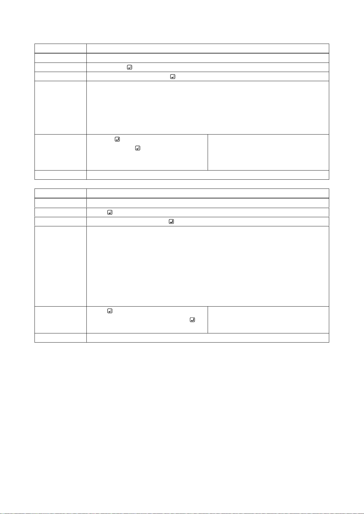
@GSS
Slot board mounting status
Function
Getting
Format
@GSS,board
Return value
@GSS,board,slot1, ・・・,slot4
Parameter
board: Selecting slot board
0 = Input slot board, 1 = Output slot board
slot1 to slot4 : Slot board mounting status
0 = Slot board is not mounted., 1 = Digital slot board is mounted,
2 = HDBaseT slot board is mounted, 3 = Optical slot board is mounted
Example
@GSS,0
@GSS,0,1,1,0,0
Getting input slot board status.
Input slots 1 and 2: digital slot board is
mounted; input slots 3 and 4: no slot board
is mounted.
Remarks
-
@GIV
Version
Function
Getting
Format
@GIV
Return value
@GIV,id,version,input,output
Parameter
id: Model number
version : Firmware version
input: The number of inputs
1 to 16
output: The number of outputs
1 to 16
Example
@GIV
@GIV,FDX-16 ,1.00R0,16,16
Getting firmware version.
Firmware version: 1.00R0; the number of
inputs and outputs: 16
Remarks
-
41
Page 42
FDX-16 Command Guide
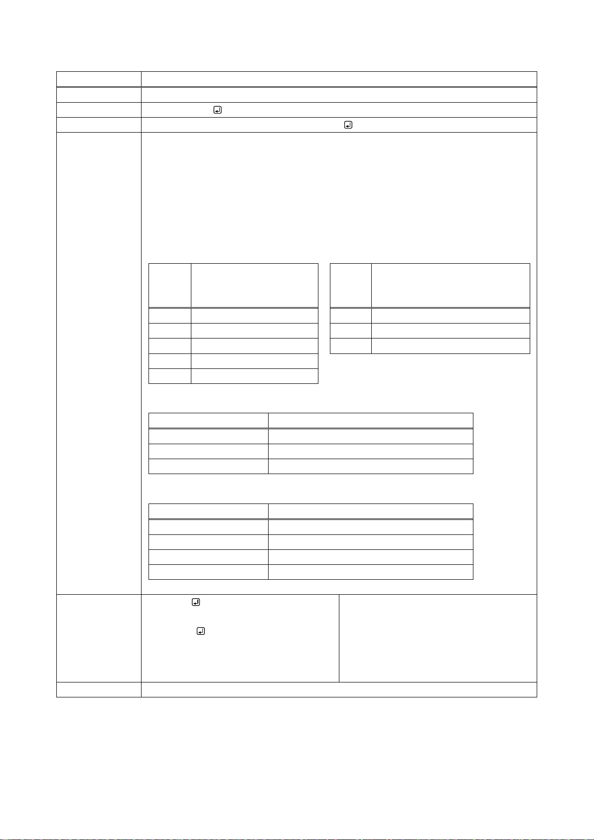
@GIS
Input signal status
Function
Getting
Format
@GIS,in,mode
Return value
@GIS,in,mode,status_1 (,status_2,status_3)
Parameter
in : Input channel
1 to 16 = INPUT1 to INPUT16
mode : Status
0 = All statuses of input signals, 1 = Input mode/Input color depth,
2 = Input resolution/vertical synchronous frequency,
3 = Input audio/Input sampling frequency
status_1 : Input mode/Input color depth
Input
mode
Description
Input
color
depth
Description
d
DVI signal, without HDCP
08
24bit / pixel ( 8bit / component)
D
DVI signal, with HDCP
10
30bit / pixel ( 10bit / component)
h
HDMI signal, without HDCP
12
36bit / pixel ( 12bit / component)
H
HDMI signal, with HDCP
N No signal input
status_2 : Input resolution/Vertical synchronous frequency
Example
Description
1920x1080p 59.94Hz
1600x1200p 60Hz
UXGA@60
NO SIGNAL
No signal input
status_3 : Input audio/Input sampling frequency
Example
Description
L-PCM 48kHz
2 channel linear PCM 48 kHz
L-PCM 48kHz M
Multiple channel linear PCM 48 kHz
COMPRESSED AUDIO
Compressed audio
NO AUDIO
No audio input
Example
@GIS,1,0
@GIS,1,0,H08,1920x1080p 59.94Hz,L-P
CM 48kHz
Getting all statuses of INPUT1.
HDMI signal; with HDCP; color depth:
24 bit/pixel (8 bit/component); input
Resolution: [email protected]; input audio:
2 channel linear PCM,
sampling frequency: 48 kHz
Remarks
-
42
Page 43
FDX-16 Command Guide
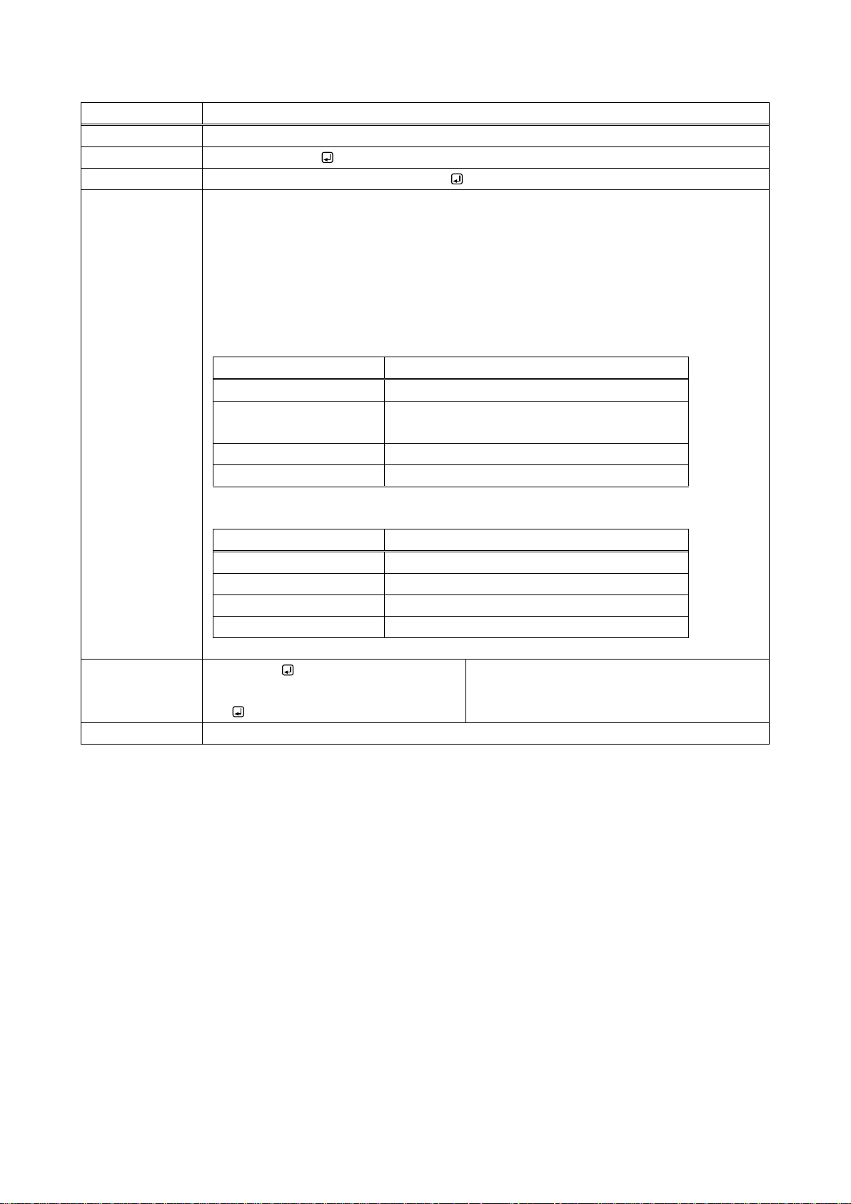
@GOS
Sink device status
Function
Getting
Format
@GOS,out,mode
Return value
@GOS,out,mode,status_1 (,status_2)
Parameter
out : Output channel
1 to 16 = OUTPUT1 to OUTPUT16
mode: Status
0 = All statuses of sink device, 1 = HDCP of sink device,
2 = HDCP authentication between the FDX and sink device
status_1 : HDCP of sink device
Status
Description
HDCP SUPPORT
HDCP compliant sink device is connected
HDCP NOT SUPPORT
Non-HDCP compliant sink device is
connected
HDCP NOT CHECK
HDCP of sink device is not checked
UNCONNECTED
Sink device is not connected
status_2: HDCP authentication between the FDX and sink device
Status
Description
HDCP OFF
Signal with HDCP is not input.
HDCP OK
Authentication succeeded.
HDCP ERROR
Authentication failed.
HDCP CHECK NOW
Being authentication processing.
Example
@GOS,1,0
@GOS,1,0,HDCP SUPPORT,HDCP
OK
Getting all statuses of OUTPUT1 sink device.
HDCP-compliant sink device is connected;
HDCP authentication is succeeded.
Remarks
-
43
Page 44
FDX-16 Command Guide
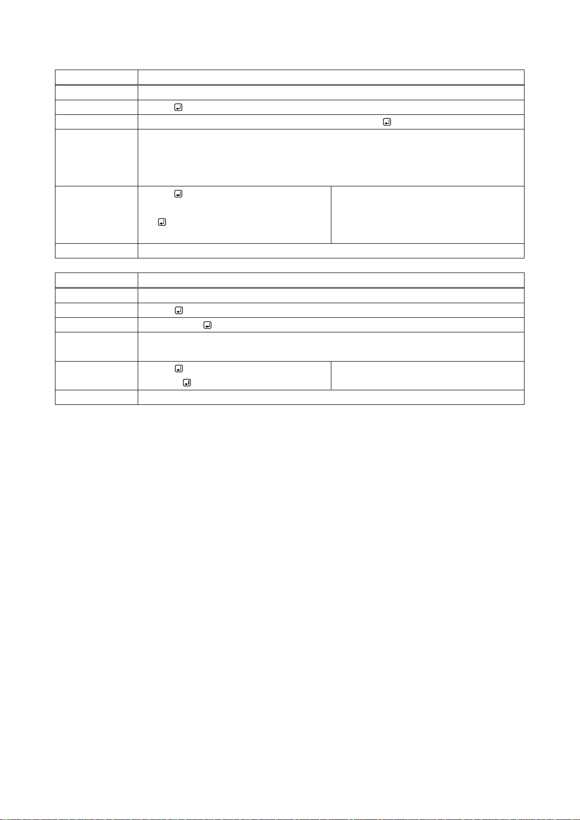
@GFS
Cooling fan status
Function
Getting
Format
@GFS
Return value
@GFS,rpm1,s1, rpm2,s2, rpm3,s3, rpm4,s4, rpm5,s5
Parameter
rpm1 to rpm5: The number of cooling fan rotation speed
s1 to s5 : Status
0 = Normal, 1 = Abnormal
Example
@GFS
@GFS,3540,0,3540,0,3540,0,3540,0,354
0,0
Getting the number of cooling fan
rotations.
All cooling fan speed: 3540; status:
Normal
Remarks
-
@GPS
Voltage status
Function
Getting
Format
@GPS
Return value
@GPS,status
Parameter
status:
0 = Normal, 1 = Abnormal
Example
@GPS
@GPS,0
Getting voltage status.
Normal
Remarks
-
44
Page 45
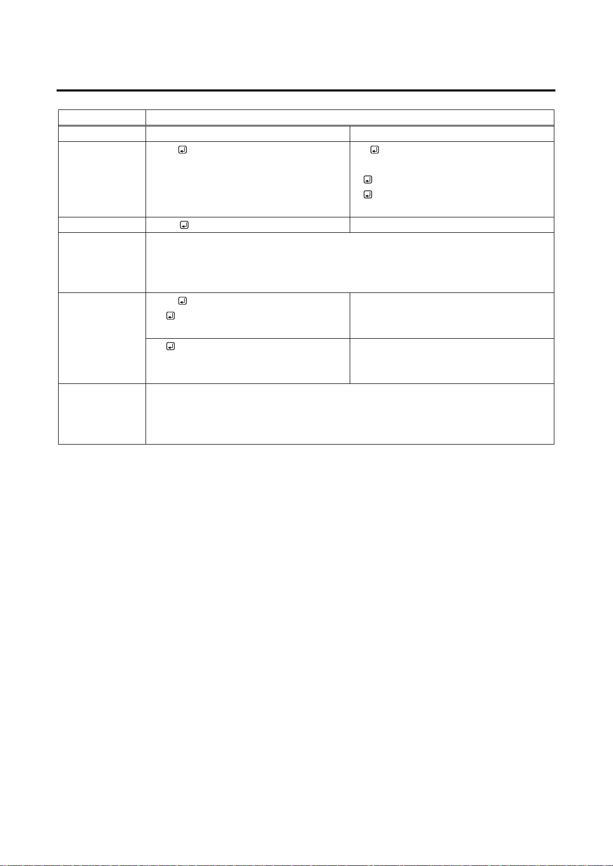
2.5.11 Compatible-mode communication command
mode / AV / V / A
Switching mode
Function
Getting
Setting
Format
mode
AV (Switching FDX and MAU-1616 I/O
channels simultaneously)
V (Switching only FDX I/O channels)
A (Switching only MAU-1616 I/O
channels)
Return value
status
-
Parameter
status: Switching mode
AV = Switching FDX and MAU-1616 I/O channels simultaneously,
V = Switching only FDX I/O channels,
A = Switching only MAU-1616 I/O channels
Example
mode
AV
Getting the switching mode.
Switching FDX and MAU-1616 I/O
channels simultaneously
AV
Setting the mode to “AV” (switching FDX
and MAU-1616 I/O channels
simultaneously).
Remarks
Once the command is executed, the mode is not changed until the FDX is restarted or
new switching mode command is received.
This mode is switched independently of the switching mode of the FDX front panel.
Every time the FDX is powered on, this mode is set to “AV”.
FDX-16 Command Guide
45
Page 46
FDX-16 Command Guide
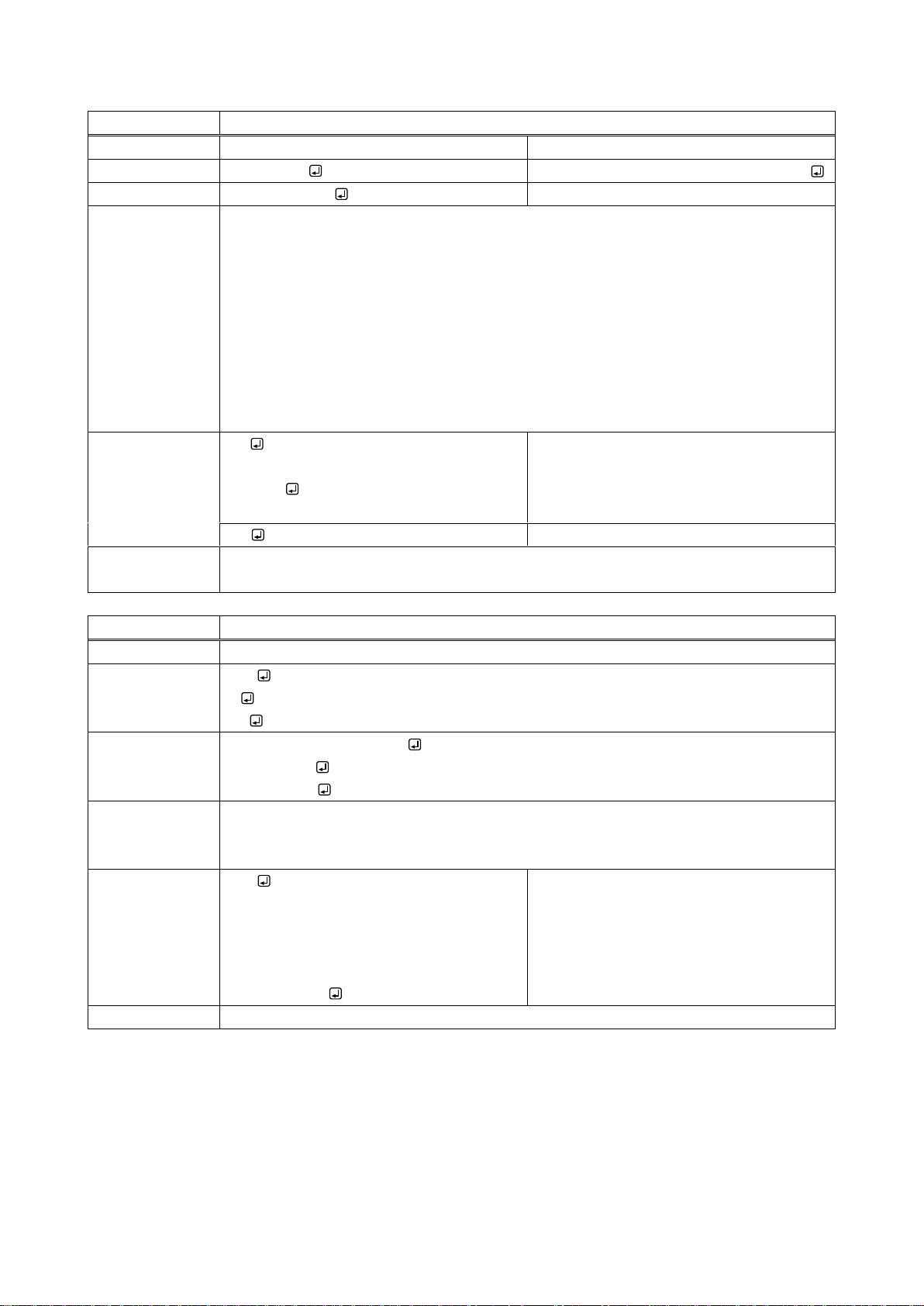
z
Switching I/O channel
Function
Getting
Setting
Format
z,output_xx
input_1,output_1 (,input_2,output_2・・・)
Return value
input_v/input_a
-
Parameter
input_1 to input_16 : Input channel
q = OFF, 0 = OFF, 1 to 16 = INPUT1 to INPUT16
output_1 to output_16 :output channel
r = All outputs (available only at the time of setting)
0 = All outputs (available only at the time of setting),
1 to 16 = OUTPUT1 to OUTPUT16
input_v : FDX input channel
input_a : MAU-1616 input channel
000 = OFF [Default], 001 to 016 = INPUT1 to INPUT16
Example
z,1
001/001
Getting the input channel that is set for
OUTPUT1.
OUTPUT1 of FDX and MAU-1616 is set to
INPUT1.
1,3
Setting OUTPUT3 to INPUT1.
Remarks
This mode is switched independently of the switching mode of the FDX front panel.
Switching mode that is set by conversion communication command will be used.
wva / w / wa
I/O channel status
Function
Getting
Format
wva (Getting I/O channel statuses of FDX and MAU-1616)
w (Getting I/O channel statuses of FDX)
wa (Getting I/O channel statuses of MAU-1616)
Return value
v_1;・・・v_16/a_1;・・・a_16 (wva command return value)
v_1;・・・v_16 (w command return value)
a_1;・・・a_16 (wa command return value)
Parameter
v_1 to v_16 : FDX output channel
a_1 to a_16 : MAU-1616 output channel
000 = OFF [Default], 001 to 016 = INPUT1 to INPUT16
Example
wva
000;000;000;000;000;000;000;000;000;00
0;000;000;000;000;000;000/000;000;000;
000;000;000;000;000;000;000;000;000;00
0;000;000;000
Getting I/O channel statuses of FDX and
MAU-1616
All output channel: Input channel is set
to OFF
Remarks
-
46
Page 47
FDX-16 Command Guide
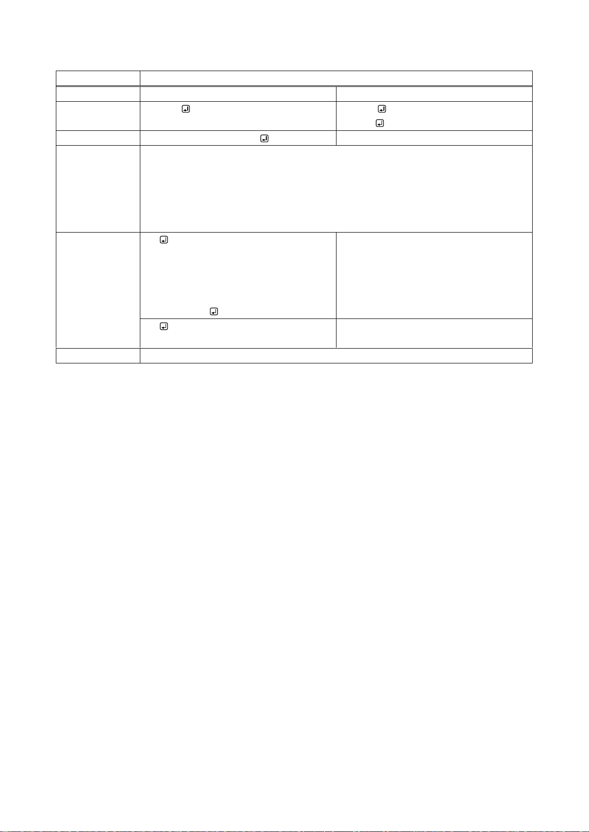
y / s / t
Getting/saving/calling preset memory
Function
Getting
Setting
Format
y,preset
s,preset (Saving preset memory)
t,preset (Calling preset memory)
Return value
v_1;・・・v_16/a_1;・・・a_16
-
Parameter
preset: Preset memory
1 to 32 = Preset memory number 1 to 32
v_1 to v_16: FDX output channel
a_1 to a_16: MAU-1616 output channel
000 = OFF, 001 to 016 = INPUT1 to INPUT16, -01 = Not control [Default]
Example
y,1
000;000;000;000;000;000;000;000;000;00
0;000;000;000;000;000;000/000;000;000;
000;000;000;000;000;000;000;000;000;00
0;000;000;000
Getting I/O channel statuses of preset
memory 1:
All I/O channel statuses: OFF
s,1
Saving I/O channel status in Preset
memory 1.
Remarks
-
47
Page 48
FDX-16 Command Guide
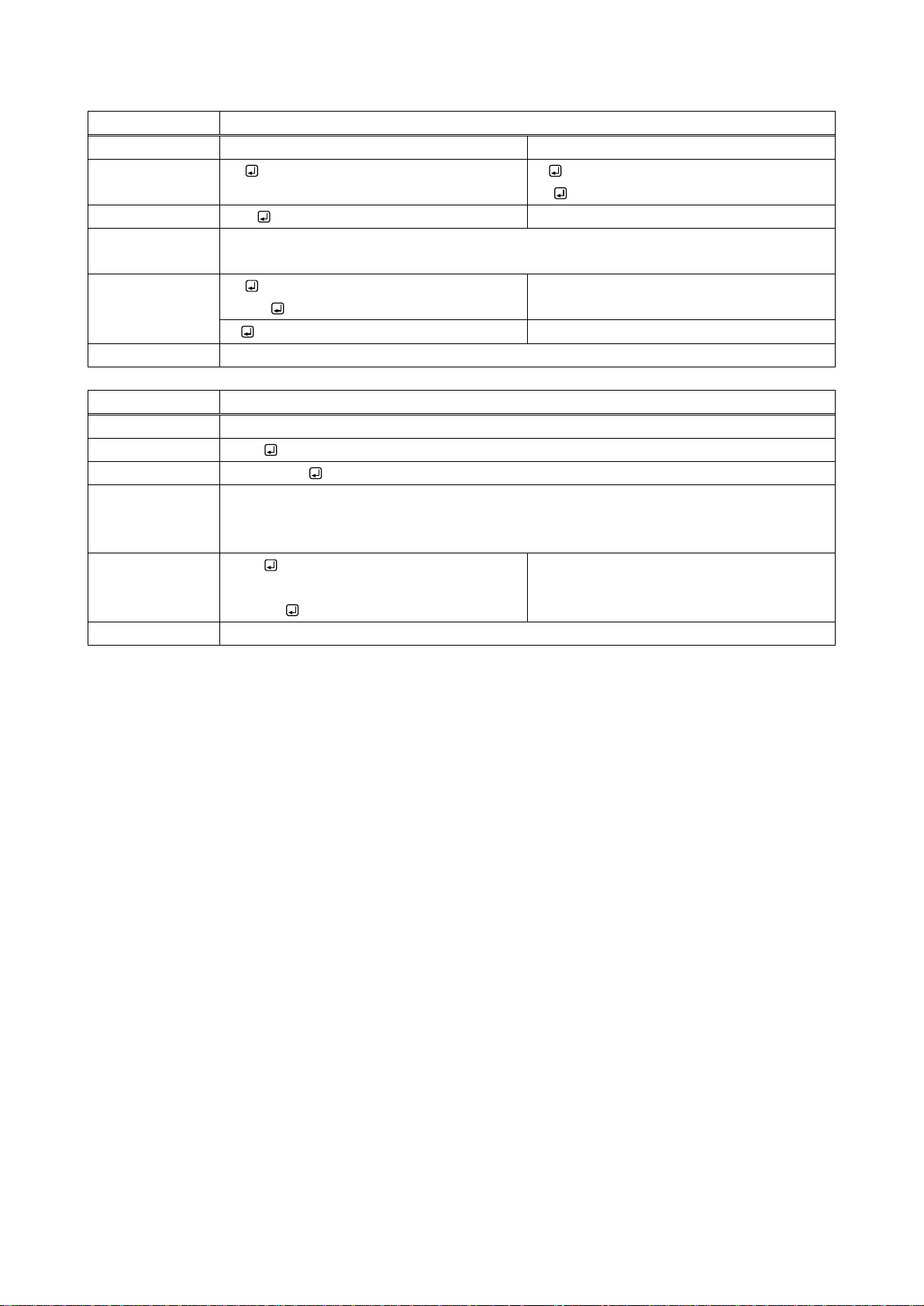
ky / kl / ku
Key lock status/setting key lock/releasing key lock
Function
Getting
Setting
Format
ky
kl (Key lock)
ku (Releasing key lock)
Return value
lock
-
Parameter
lock: Key lock status
FREE = Releasing key lock [Default], LOCK = Key lock
Example
ky
FREE
Getting key lock status.
Releasing key lock
kl
Setting key lock.
Remarks
Only target keys will be locked.
mem
Preset memory number matching I/O channel status
Function
Getting
Format
mem
Return value
video/audio
Parameter
video : Preset memory number matching FDX I/O channel status
audio : Preset memory number matching MAU-3232 channel status
000 = None, 001 to 032 = Preset memory number
Example
mem
001/001
Getting preset memory number matching
FDX I/O channel status.
The numbers will be displayed.
Remarks
If several memory numbers are matched, the smaller number will be returned.
48
Page 49
FDX-16 Command Guide
HDMI/DVI conversion cabl e
DVI cable
Cat5e/Cat6 cable
Fiber optic cable
RS-232C cable
DVI
Projector
HDBaseT output connection
Optical ou tput connection
PC
External control
FDX-16
RS-232C
OPF-RH1 000
HDC-R s eries
RS-232C
Projector
HDMI/DVI
RS-232C
INPUT
~1 4
INPUT
~5 8
INPUT
~9 12
INPUT
~13 16
A D
A D
A D
A D
~1 4
~5 8
~9 12
~13 16
OUTPUT
OUTPUT
OUTPUT
OUTPUT
A D
A D
A D
A D
FG
BREAKER
AC 100-240V
50/60Hz
S/N
OPTIONRS-232C LAN
UPDATE
ALARM
DVI-D(HDMI) DVI-D(HDMI) DVI-D(HDMI) DVI-D(HDMI)
A B C D
DVI-D(HDMI) DVI-D(HDMI) DVI-D(HDMI) DVI-D(HDMI)
A B C D
DVI-D(HDMI) DVI-D(HDMI) DVI-D(HDMI) DVI-D(HDMI)
A B C D
DVI-D(HDMI) DVI-D(HDMI) DVI-D(HDMI) DVI-D(HDMI)
A B C D
A
RX TX RX TX RX TX RX TX
B C D
OPTICAL OPTICAL OPTICAL OPTICAL
A
RX TX RX TX RX TX RX TX
B C D
OPTICAL OPTICAL OPTICAL OPTICAL
LINK LINK LINK LINK
HDBaseTA B C DHDBaseT HDBaseT HDBaseT
LINK LINK LINK LINK
HDBaseTA B C DHDBaseT HDBaseT HDBaseT
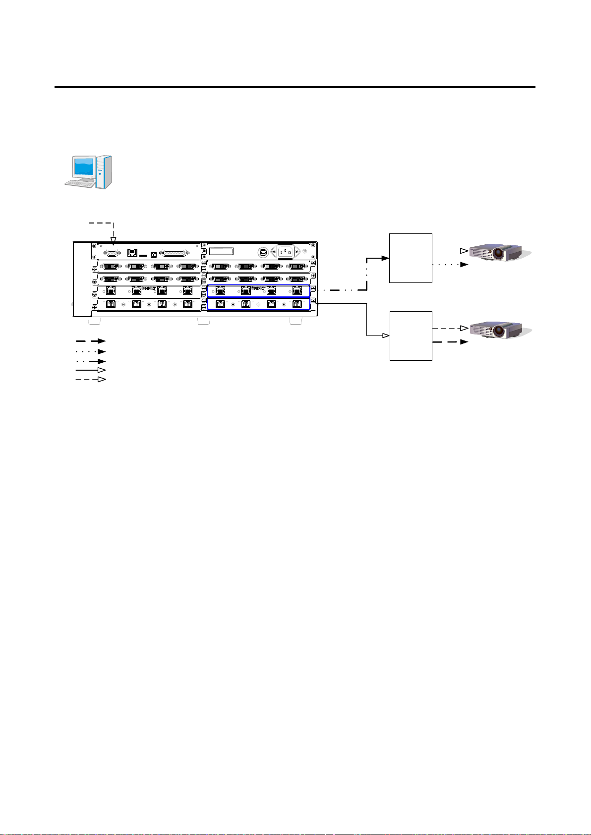
2.5.12 RS-232C transmission mode
Sink devices connected to HDC-R series and OPF-RH1000 via RS-232C can be controlled using FD
X’s HDBaseT output slot board or optical output slot board.
【Ref. 2.1.1 Setup RS-232C communication】
[Fig. 2.10] Example of RS-232C transmission mode
49
Page 50
FDX-16 Command Guide
①
@SCT,1,1,0,0
Setting RS-232C communication as follows: baud rate: 9600 bps; data bit
length: 8 bit, parity check: none; stop bit: 1 bit
②
@S++,12,16
Setting RS-232C transmission sending channel,
specifying OUTPUT12 and OUTPUT16
③
@S+R,12
Setting to RS-232C transmission receiving, specifying OUTPUT12
④
@S+S,1
Setting to RS-232C transmission mode
After this, received data is sent to OUTPUT12,OUTPUT16 set by
@S++.
⑤
POWER ON
Sending projector powered ON command
⑥
OK
Receiving projector powered ON command
⑦
@S+S,0
Setting to RS-232C transmission normal mode
After this, command can be sent to the FDX.
⑧
@GIV
Getting versions
Projecotr
PC
External control
OPF-RH1 000
HDC-R s eries
Data can be received from
the projector according to ③
setting.
FDX-16
Only one channel can receive data from
the projector according to ③ setting.
⑤ POWER ON
Sending ⑤ data from the PC
according to ② setting.
Sending ⑤ data from PC
according to ② setting.
⑤ POWER ON
⑤ POWER ON
⑥ OK
⑥ OK
⑥ OK
Projector
⑤ POWER ON
⑥ OK
INPUT
~1 4
INPUT
~5 8
INPUT
~9 12
INPUT
~13 16
A D
A D
A D
A D
~1 4
~5 8
~9 12
~13 16
OUTPUT
OUTPUT
OUTPUT
OUTPUT
A D
A D
A D
A D
FG
BREAKER
AC 100-240V
50/60Hz
S/N
OPTIONRS-232C LAN
UPDATE
ALARM
DVI-D(HDMI) DVI-D(HDMI) DVI-D(HDMI) DVI-D(HDMI)
A B C D
DVI-D(HDMI) DVI-D(HDMI) DVI-D(HDMI) DVI-D(HDMI)
A B C D
DVI-D(HDMI) DVI-D(HDMI) DVI-D(HDMI) DVI-D(HDMI)
A B C D
DVI-D(HDMI) DVI-D(HDMI) DVI-D(HDMI) DVI-D(HDMI)
A B C D
A
RX TX RX TX RX TX RX TX
B C D
OPTICAL OPTICAL OPTICAL OPTICAL
A
RX TX RX TX RX TX RX TX
B C D
OPTICAL OPTICAL OPTICAL OPTICAL
LINK LINK LINK LINK
HDBaseTA B C DHDBaseT HDBaseT HDBaseT
LINK LINK LINK LINK
HDBaseTA B C DHDBaseT HDBaseT HDBaseT
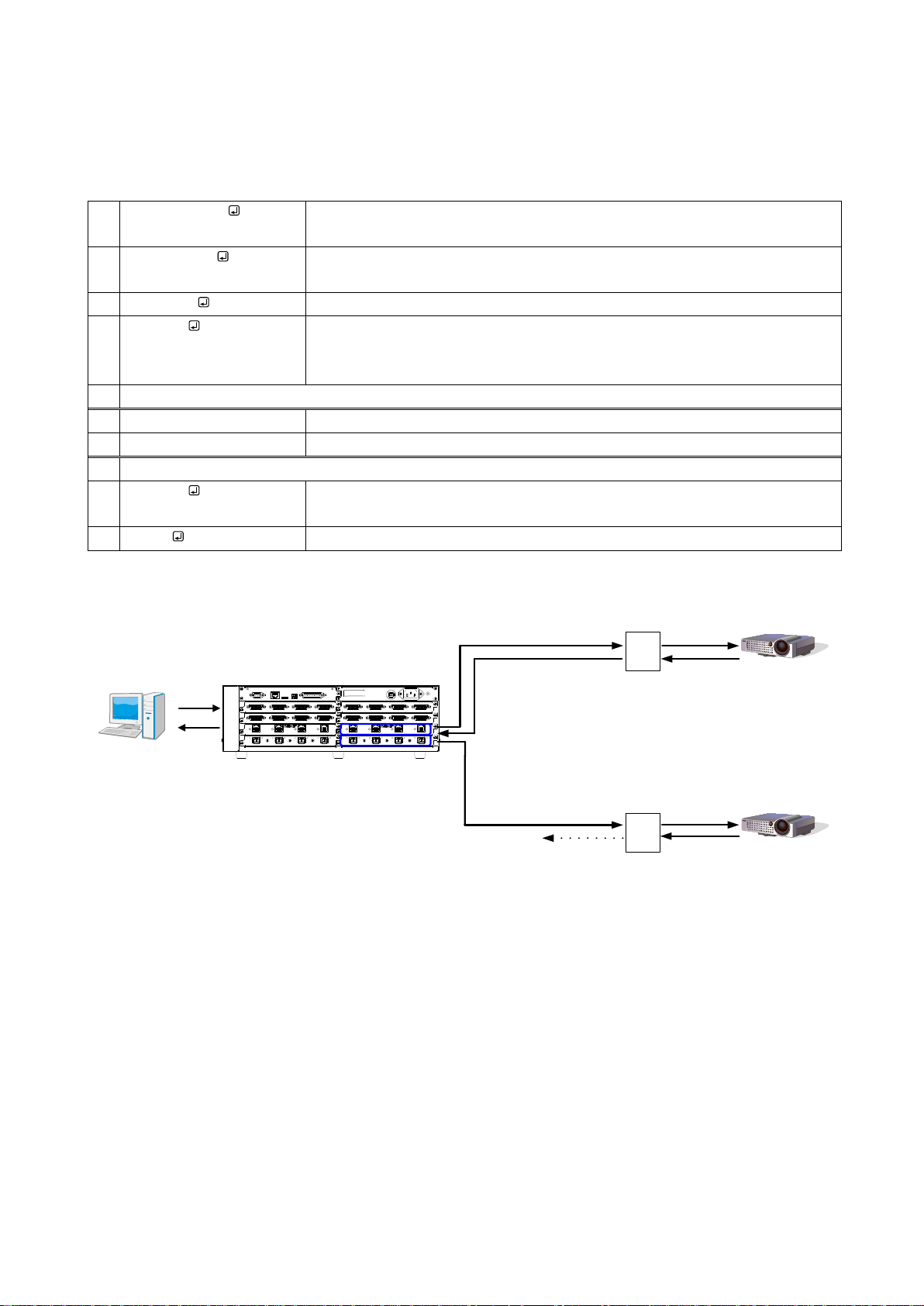
When the transmission mode is set to RS-232C transmission mode, received data will be sent to the specified
output channel until normal mode is set.
Several sending channels can be set while only 1 receiving channel can be set.
Example: Sending data to OUTPUT12 and OUTPUT16 and receiving the data from OUTPUT12.
[Fig. 2.11] Transmitting/receiving RS-232C transmission mode
50
Page 51
FDX-16 Command Guide
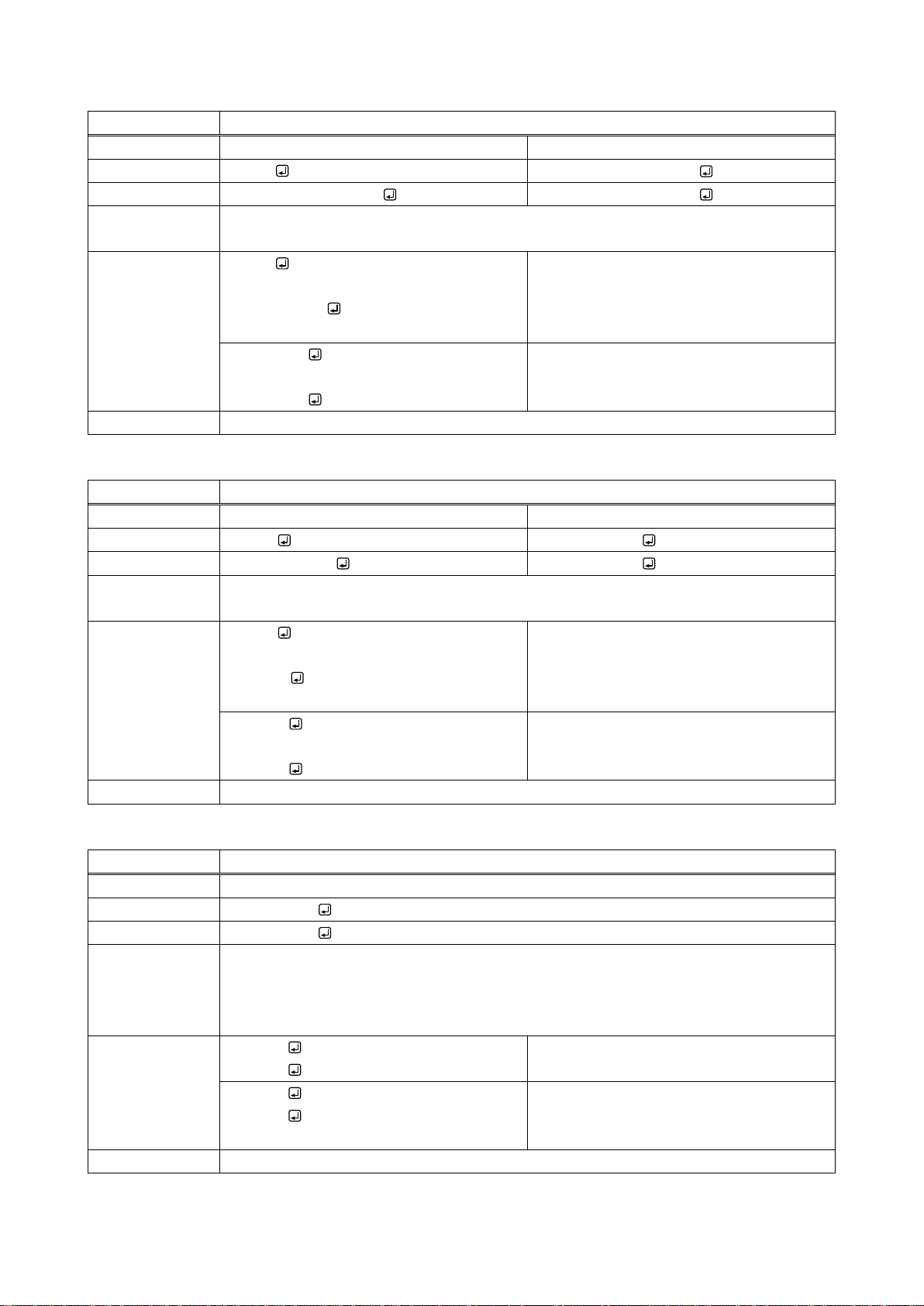
@G++ / @S++
RS-232C transmission sending channel setting
Function
Getting
Setting
Format
@G++
@S++,ch_1 (,ch_2,・・・)
Return value
@G++,ch_1,・・・ch_16
@S++,ch_1 (,ch_2,・・・)
Parameter
ch_1 to ch_16: RS-232C transmission sending channel
1 to 16 = OUTPUT1 to OUTPUT16
Example
@G++
@G++,1,2,3,4
Getting status of RS-232C transmission
sending channel.
OUTPUT1 to OUTPUT 4: RS-232C
transmission sending channel
@S++,1,16
@S++,1,16
Setting OUTPUT1 and OUTPUT16 to
RS-232C transmission sending channel.
Completed normally.
Remarks
-
@G+R / @S+R
RS-232C transmission receiving channel setting
Function
Getting
Setting
Format
@G+R
@S+R,channel
Return value
@G+R,channel
@S+R,channel
Parameter
channel:RS-232C transmission receiving channel
1 to 16 = OUTPUT1 to OUTPUT16
Example
@G+R
@G+R,4
Getting status of RS-232C transmission
receiving channel.
OUTPUT4: RS-232C transmission
receiving channel.
@S+R,1
@S+R,1
Setting OUTPUT1 to RS-232C
transmission receiving channel.
Completed normally.
Remarks
-
@S+S
RS-232C transmission
Function
Setting
Format
@S+S,mode
Return value
@S+S,mode
Parameter
mode: Setting RS-232C transmission mode
0 = Normal mode, 1 = RS-232C transmission mode
After setting to RS-232C transmission mode, RS-232C is used for the communication
with FDX until a normal mode command is received.
Example
@S+S,1
@S+S,1
Setting to RS-232C transmission mode.
Completed normally.
@S+S,0
@S+S,0
Setting RS-232C transmission mode to
normal mode.
Completed normally.
Remarks
-
51
Page 52
FDX-16 Command Guide
Headquarters
IDK Corporation
7-9-1 Chuo, Yamato-shi, Kanagawa-pref.
242-0021 JAPAN
TEL: +81-46-200-0764 FAX: +81-46-200-0765
Email: [email protected] URL: http: //www.idk.co.jp/en/index.html
USA
IDK America Inc.
72 Grays Bridge Road Suite 1-C, Brookfield, CT 06804
TEL: +1-203-204-2445
Email: [email protected] URL: http: //www.idkav.com
Europe
IDK Europe GmbH
Lise-Meitner-Str. 6, D-40878 Ratingen
Email: [email protected] URL: http: //www.idkav.eu
Product information
Support
Arvanics Corporation
3-8-3-3F Yamato Higashi, Yamato-shi, Kanagawa-pref.
242-0017 JAPAN
TEL: +81-46-259-6920 FAX: +81-46-259-6930
Email: [email protected] URL: http: //www.arvanics.com
FDX-16 User’s guide (Command Guide)
Ver.1.0.1
Revised on: 25 February 2016
Information in this document is subject to change without notice.
All rights reserved. All trademarks mentioned are the property of their respective owners.
52
 Loading...