

Page 1
Page 2

i
Notice
MS3390 is a lightweight programmable data terminal. A SDK based on C is provided including
user-friendly IDE and fully functional APIs.
Before operating the terminal, please make sure you carefully read the following information to ensure
that your terminal is able to perform at the level for which it is designed.
1. All software, including firmware, furnished to the user is on a licensed basis.
2. The right is reserved to make changes to any software or product to improve reliability, function, or
design.
3. The contents of this manual are subject to change without notice.
4. The manufacturer assumes no responsibility for any loss or claims by third parties which may arise
from the use of this manual.
5. Do not throw or drop the terminal or otherwise subject it to strong impact, which can damage the
terminal, interrupt program execution, corrupt memory contents, or otherwise interfere with proper
operation.
6. A standard packing includes a terminal, a USB cable and a CD (containing software and electrical
manuals). Accessory includes a Bluetooth USB adapter BA2110 which supports reliable wireless
data transmission and an AC/DC adaptor for battery charge.
7. Please charge the battery before the first time of use.
8. The term “terminal” as used in this manual denotes the MS3390 terminal unless otherwise noted.
Page 3

ii
Page 4

iii
Contents
Notice ............................................................................................................................................... i
Contents .......................................................................................................................................... iii
1 Specifications ................................................................................................................................ 1
1-1 Technical specifications ................................................................................................................ 1
1-2 Default settings for each barcode ................................................................................................. 3
1-3 Decode zone ................................................................................................................................. 4
1-4 Dimensions ................................................................................................................................... 5
1-5 Parts of the terminal ...................................................................................................................... 6
1-6 Parts of the Bluetooth USB adapter BA2110 ............................................................................... 7
1-7 Keys, actions and features ........................................................................................................... 8
2 Introduction to installation .............................................................................................................. 9
2-1 Installing a USB HID keyboard wired terminal ............................................................................. 9
2-2 Installing a USB virtual COM wired terminal ................................................................................ 9
2-3 Attaching the neck/wrist strap ..................................................................................................... 10
2-4 Replacing the Lithium-ion battery ............................................................................................... 10
3 Getting started ............................................................................................................................ 11
3-1 Power on/off terminal .................................................................................................................. 11
3-2 Charge battery ............................................................................................................................ 11
3-3 Enter/Exit sleep mode ................................................................................................................. 11
3-4 Power on/off Bluetooth ............................................................................................................... 11
4 Introduction to LCD display .......................................................................................................... 12
4-1 LCD display icons ....................................................................................................................... 12
4-2 LCD display menu ...................................................................................................................... 13
5 Operations of the terminal ............................................................................................................ 15
5-1 Scan ............................................................................................................................................ 15
5-1-1 Scan Mode ....................................................................................................................... 15
5-1-2 Input Data Manually ......................................................................................................... 16
5-1-3 Quantity Enter .................................................................................................................. 16
5-1-4 Add Time .......................................................................................................................... 17
5-1-5 Add Date........................................................................................................................... 17
5-1-6 Set Separator ................................................................................................................... 17
5-1-7 Database Query ............................................................................................................... 17
5-1-8 Avoid Duplication .............................................................................................................. 18
5-1-9 Barcode Statistics ............................................................................................................. 18
5-1-10 Sum Total ....................................................................................................................... 18
5-1-11 List Files ......................................................................................................................... 18
5-1-12 Transfer Confirm ............................................................................................................ 19
Page 5

iv
5-2 Data Transfer .............................................................................................................................. 20
5-2-1 Bluetooth .......................................................................................................................... 20
5-2-2 USB HID Keyboard .......................................................................................................... 20
5-2-3 USB Virtual COM ............................................................................................................. 20
5-2-4 U Disk ............................................................................................................................... 20
5-3 System Setting - Bluetooth ......................................................................................................... 23
5-3-1 Bluetooth Functionalities .................................................................................................. 23
5-3-2 Configure Bluetooth HID Keyboard Profile Communication ............................................ 23
5-3-3 Configure Bluetooth SPP Slave Profile Communication ................................................. 27
5-3-4 Configure Bluetooth SPP Master Profile Communication ............................................... 28
5-3-5 Configure Bluetooth USB Adapter BA2110 ..................................................................... 29
5-3-6 Configure the Profile of BA2110....................................................................................... 30
5-4 System Setting - General............................................................................................................ 32
5-4-1 Language.......................................................................................................................... 32
5-4-2 Volume of Beeper ............................................................................................................. 32
5-4-3 Vibrator ............................................................................................................................. 32
5-4-4 Backlight Timeout ............................................................................................................. 32
5-4-5 Sleeping Timeout ............................................................................................................. 32
5-4-6 Default Setting .................................................................................................................. 32
5-4-7 System Password ............................................................................................................. 33
5-5 System Information ..................................................................................................................... 34
5-5-1 View Memory .................................................................................................................... 34
5-5-2 Bluetooth Module ............................................................................................................. 34
5-5-3 Firmware Version ............................................................................................................. 34
6 User customized application software for MS3390 ........................................................................ 35
6-1 Auto Run ..................................................................................................................................... 35
6-2 Execute ....................................................................................................................................... 35
6-3 Delete .......................................................................................................................................... 35
6-4 Download .................................................................................................................................... 35
6-5 Installation Key............................................................................................................................ 36
6-6 Verification Code......................................................................................................................... 36
7 Parameter menus ........................................................................................................................ 37
7-1 Example: Programming .............................................................................................................. 37
7-2 Some global settings .................................................................................................................. 38
7-3 UPC-A ......................................................................................................................................... 40
7-4 UPC-E ......................................................................................................................................... 42
7-5 UPC-E1 ....................................................................................................................................... 44
7-6 EAN-13 ....................................................................................................................................... 46
7-7 EAN-8.......................................................................................................................................... 48
Page 6

v
7-8 Code 39 ...................................................................................................................................... 49
7-9 Interleaved 2 of 5 ........................................................................................................................ 51
7-10 Industrial 2 of 5 ......................................................................................................................... 52
7-11 Matrix 2 of 5 .............................................................................................................................. 53
7-12 Codabar .................................................................................................................................... 54
7-13 Code 128 .................................................................................................................................. 56
7-14 UCC/EAN 128 ........................................................................................................................... 57
7-15 ISBT 128 ................................................................................................................................... 58
7-16 Code 93 .................................................................................................................................... 60
7-17 Code 11 .................................................................................................................................... 61
7-18 MSI/Plessey .............................................................................................................................. 62
7-19 UK/Plessey ............................................................................................................................... 63
7-20 China Post ................................................................................................................................ 64
7-21 China Finance ........................................................................................................................... 65
7-22 Telepen ..................................................................................................................................... 68
7-23 GS1 DataBar (GS1 DataBar Truncated) .................................................................................. 70
7-24 GS1 DataBar Limited ................................................................................................................ 71
7-25 GS1 DataBar Expanded ........................................................................................................... 72
7-26 G1-G6 & FN1 substitution string setting ................................................................................... 73
7-27 G1-G4 string position & Code ID position ................................................................................ 77
7-28 String transmission ................................................................................................................... 78
8 Barcode representing non-printable character ............................................................................... 80
9 ASCII Table ................................................................................................................................ 81
10 Test Chart ................................................................................................................................. 82
11 Configuration alphanumeric entry barcode .................................................................................. 84
Appendix A: Connect iPhone to MS3390 via Bluetooth ..................................................................... 85
Appendix B: Pop up the Apple iOS on-screen keyboard ................................................................... 86
Page 7

vi
Page 8

1
1 Specifications
1-1 Technical specifications
Table 1-1. Technical specifications
Radio link
2.4 ~ 2.5GHz (ISM band), Bluetooth V2.1+EDR, class 2
Working range
30 meters (line of sight)
Interface
Bluetooth:
Human Interface Device (HID) Keyboard
Serial Port Profile (SPP), operating as either a master or a slave
USB:
USB HID keyboard
USB virtual COM
U Disk (with which barcode data is stored in a txt file rather than sent to a host via
Bluetooth/USB)
Data storage
16 MB for out of range batch/data batch mode: 1,118,480 barcodes (each barcode is
of 15 bytes);
96 MB for U Disk mode: 1,509,949,440 barcodes (each barcode is of 15 bytes).
Keyboard layout
USA, Turkish F/Q, French, Italian, Spanish, Slovak, Denmark, Japanese, German
Dimensions
Length × Width × Depth: 11.0 × 4.3 × 2.7 cm
Weight
89g
Color
Black/White/ Customization
Case material
ABS
Indicator
Beeper, LED, Vibrator
Display
LCD monochrome display (128 × 64) with LED backlight
Input Voltage
4.75V – 5.25V
Operating current
5mA (sleeping); 165mA (scanning); 110mA (transmitting)
Battery
950 mAh Lithium-ion battery
Charge time
Fully charged (>80%) in 3.5 hours
Charge current
300 mA
Standby time
Over 7 days
Operating time
10 hours based on 1 scan/5 seconds
Read barcodes per
charge
Over 20,000 scans per charge
Light source
650 nm visible laser diode
Scanning angle
±50°, ±65°, ±35° (Skew, Pitch, Roll)
Scan rate
100±10 times/sec
Decode capability
UPC-A, UPC-E, EAN-13, EAN-8, ISBN/ISSN, Code 39, Code 39 full ASCII, Code
32, Trioptic Code 39, Interleaved 2 of 5, Industrial 2 of 5, Matrix 2 of 5, Codabar
(NW7), Code 128, Code 93, Code 11 (USD-8), MSI/Plessey, UK/Plessey,
UCC/EAN 128, China Post, Telepen, GS1 Data Bar (formerly RSS) variants
Decoding depth
(1 mil = 0.0254mm)
Page 9
2
& Max. resolution
4 mil: 40mm (50±10 - 90±10mm)
5 mil: 65mm (50±10 - 115±10mm)
10 mil: 240mm (20±10 - 260±20mm)
15 mil: 350mm (30±10 - 380±20mm)
20 mil: 445mm (45±10 - 490±30mm)
30 mil: 660mm (40±10 - 700±30mm)
55 mil: 780mm (80±10 - 850±100mm)
Temperature
0° to 50°C (32° to 120°F), Operating; -40° to 60°C (-40° to 140°F), Storage
Humidity
5% to 95% (non-condensing)
Operating mode
Handheld
Programming method
Manual (reading special barcode), On-Screen (pressing special keys)
Firmware upgrade
Online via USB interface
Safety
Laser safety: EN60825-1, class 1
EMC: EN 55022, EN 55024
Electrical safety: EN 60950-1
ESD: ±8KV air discharge, ±4KV direct discharge
Drop resistance: Multiple 1.5m (4.9ft) drops to concrete
Protection class: IP64
Environmental: RoHS compliant
Table 1-2. Technical specifications of BA2110
Radio link
2.4 ~ 2.5GHz (ISM band), Bluetooth V2.1+EDR, class 2
Working range
30 meters (line of sight)
Dimensions
Length × Width × Depth: 7.6 × 2.2 × 0.8 cm
Weight
12g
Notes:
1- BA2110 is a Bluetooth USB adapter made by the manufacturer, which supports reliable wireless data
transmission.
2- BA2110 is an optional accessory.
Page 10

3
1-2 Default settings for each barcode
Table 1-3. Default settings
Code type
Read
enable
Check digit
verification
Check digit
transmission
Min. code
length
Proprietary
code ID
AIM
code ID
UPC-A
√ √ √
(12)2
A
]Em
UPC-E
√ √ √
(8)2
D
]Em
EAN-13
√ √ √
(13)2
A
]Em
EAN-8
√ √ √
(8)2
C
]Em
ISBN/ISSN1
√ √ √
(13)2
A
]Em
Code 39
√ - - 1 M
]Am
Interleaved 2 of 5
√ - - 6 I
]Im
Industrial 2 of 5
- - - 4 H
]Im
Matrix 2 of 5
√ - - 6 X
]Im
Codabar
√ - - 4 N
]Fm
Code 128
√ √ - 1 K
]Cm
Code 93
√ √ - 1 L
]Gm
Code 11
- √ - 4 V
-
MSI/Plessey
- - - 4 O
]Mm
UK/Plessey
√ √ - 1 U
]Mm
UCC/EAN 128
√ √ - 1 K
]Cm
China Post
√ - -
(11)2
T
]Im
Telepen
√ √ - 1 P
]Em
GS1 DataBar
√ - -
(16)2
R
]em
GS1 DataBar Truncated3
√ - -
(16)2
R
]em
GS1 DataBar Limited
√ - -
(16)2
R
]em
GS1 DataBar Expanded
√ - - 1 R
]em
Note: 1The settings for ISBN/ISSN and EAN-13 must be the same.
2 Fixed-length barcodes.
3The settings for GS1 DataBar Truncated and GS1 DataBar must be the same.
Page 11
4
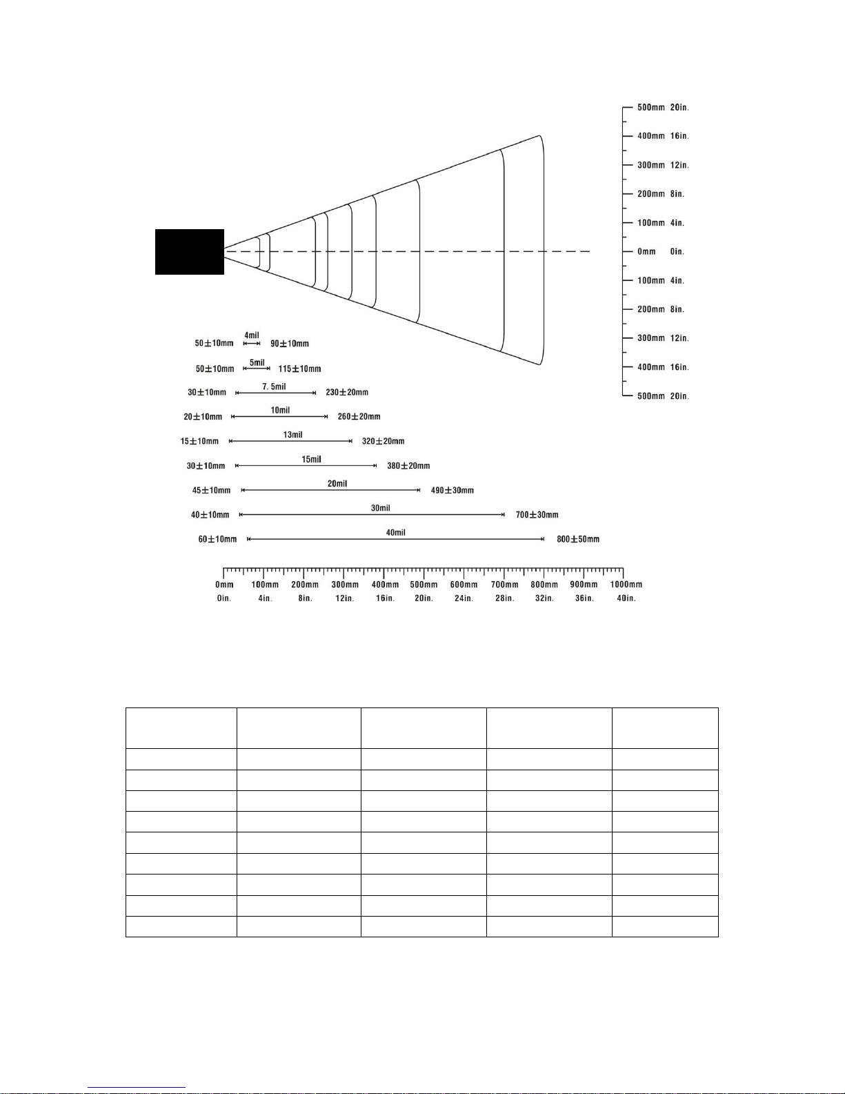
1-3 Decode zone
Figure 1-1. Decode zone
Table 1-4. Description of barcode patterns applied in Figure 1-1
Resolution
Barcode type
Wide-narrow
element ratio
Barcode content
Contrast
4.0 mil
Code 39
2.5:1
ABCDEFGH
80%
5.0 mil
Code 39
2.5:1
ABCDEFGH
80%
7.5 mil
Code 39
2.5:1
ABCDEF
80%
10 mil
Code 39
2.5:1
ABCDE
90%
13 mil
100% UPC
-
12345678905
90%
15 mil
Code 39
2.5:1
ABCD
80%
20 mil
Code 39
2.2:1
123
80%
40 mil
Code 39
2.2:1
AB
80%
55 mil
Code 39
2.2:1
CD
80%
Terminal
Page 12
5
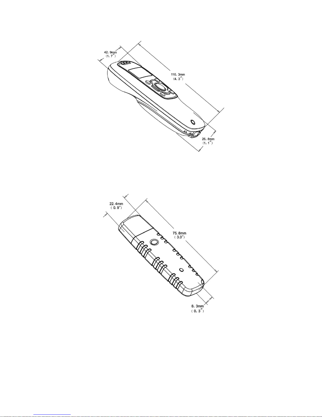
1-4 Dimensions
Figure 1-2. Dimensions of the terminal
Figure 1-3. Dimensions of the Bluetooth USB adapter
Page 13
6
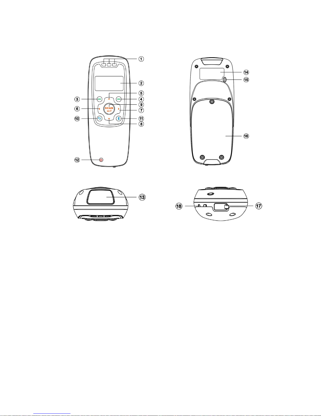
1-5 Parts of the terminal
Front view
Back view
Top view
Bottom view
Figure 1-4. Parts of the terminal
○
1 Blue LED (Bluetooth power); Green LED (Decode success); Red LED (Charging indicator)
○
2 LCD
○
3 Left soft key
○
4 Right soft key
○
5 Up navigation key
○
6 Left navigation key
○
7 Right navigation key
○
8 Down navigation key
○
9 Scan/Select key
○
10 Return key
○
11 Bluetooth on/off key
○
12 Power/Sleep key
○
13 Scan window
○
14 Label
○
15 Beeper
○
16 Battery cover
○
17 Mini USB port / Battery charging port (Lift cover)
○
18 Hook for neck/wrist strap
Page 14
7
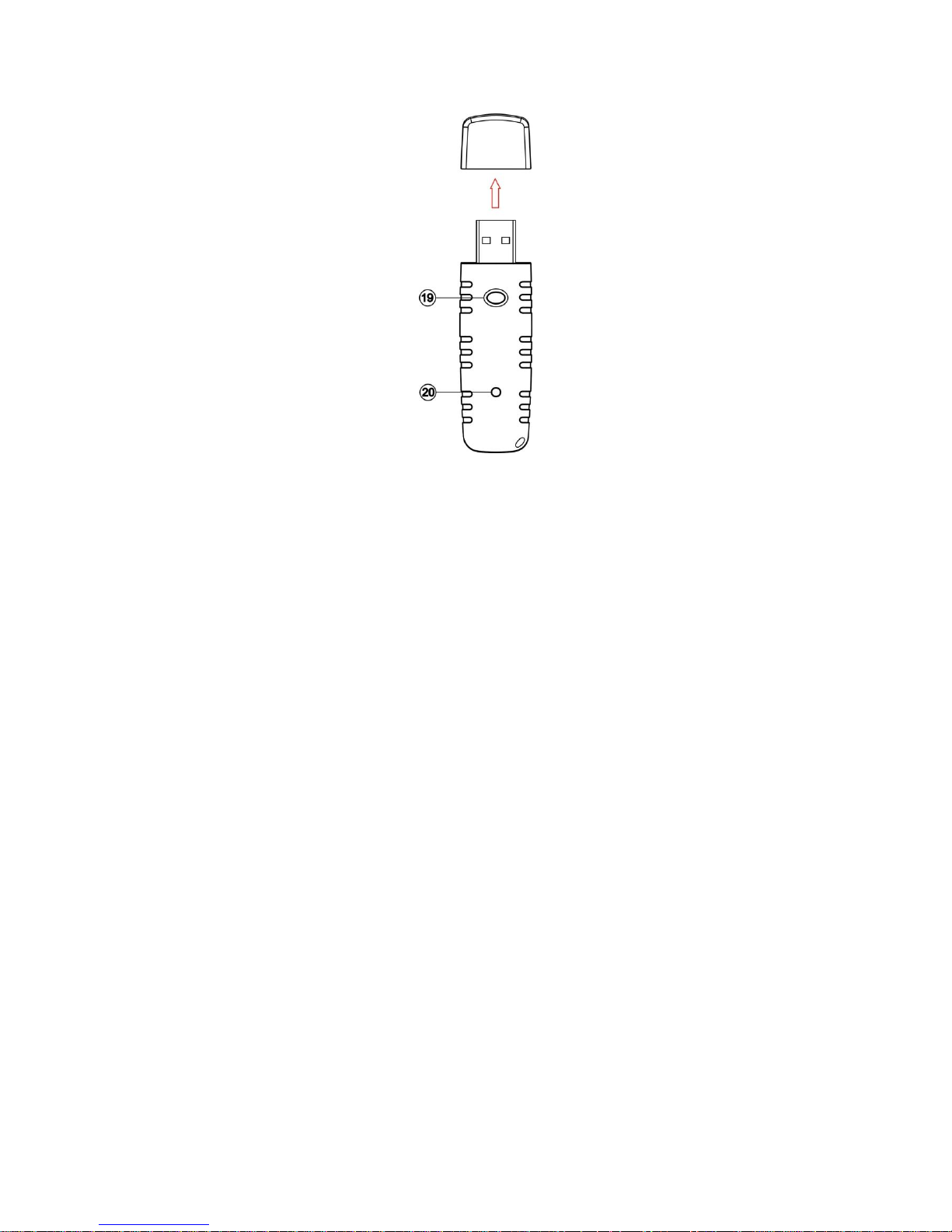
1-6 Parts of the Bluetooth USB adapter BA2110
Figure 1-5. Parts of the Bluetooth USB adapter BA2110
○
19 Reset/Firmware upgrade key
○
20 Green LED (Power/Data transmission)
Page 15

8
1-7 Keys, actions and features
Operations, such as scrolling and selecting menus, moving a cursor, or scanning a barcode, are
controlled by trigger keys and stroke keys.
Table 1-4. Key functions
Part Position1
Key/Action/Feature
Description
○
3
Left soft key
Functionalities are identified by the screen display. In general,
the acknowledge/non-acknowledge of operations are done by
pressing a soft key.
○
4
Right soft key
○
9
Scan/Select key
is pressed to scan barcodes when the terminal is not in a menu
status; the select key is pressed to select items when a menu is
activated.
○
5
Up navigation key
is pressed to move cursor upward/downward.
○
8
Down navigation key
○
6
Left navigation key
is pressed to move cursor leftward/rightward.
○
7
Right navigation key
○
10
Return key
is pressed to return to previous menu by one step.
○
11
Bluetooth on/off key
is pressed to turn on/off the Bluetooth power.
○
12
Power/Sleep key
is pressed long to power on/off a terminal; the key is pressed
short to enter/exit sleep mode.
Note: 1See 1-5 Parts of the terminal for the information about position of keys.
Page 16
9
2 Introduction to installation
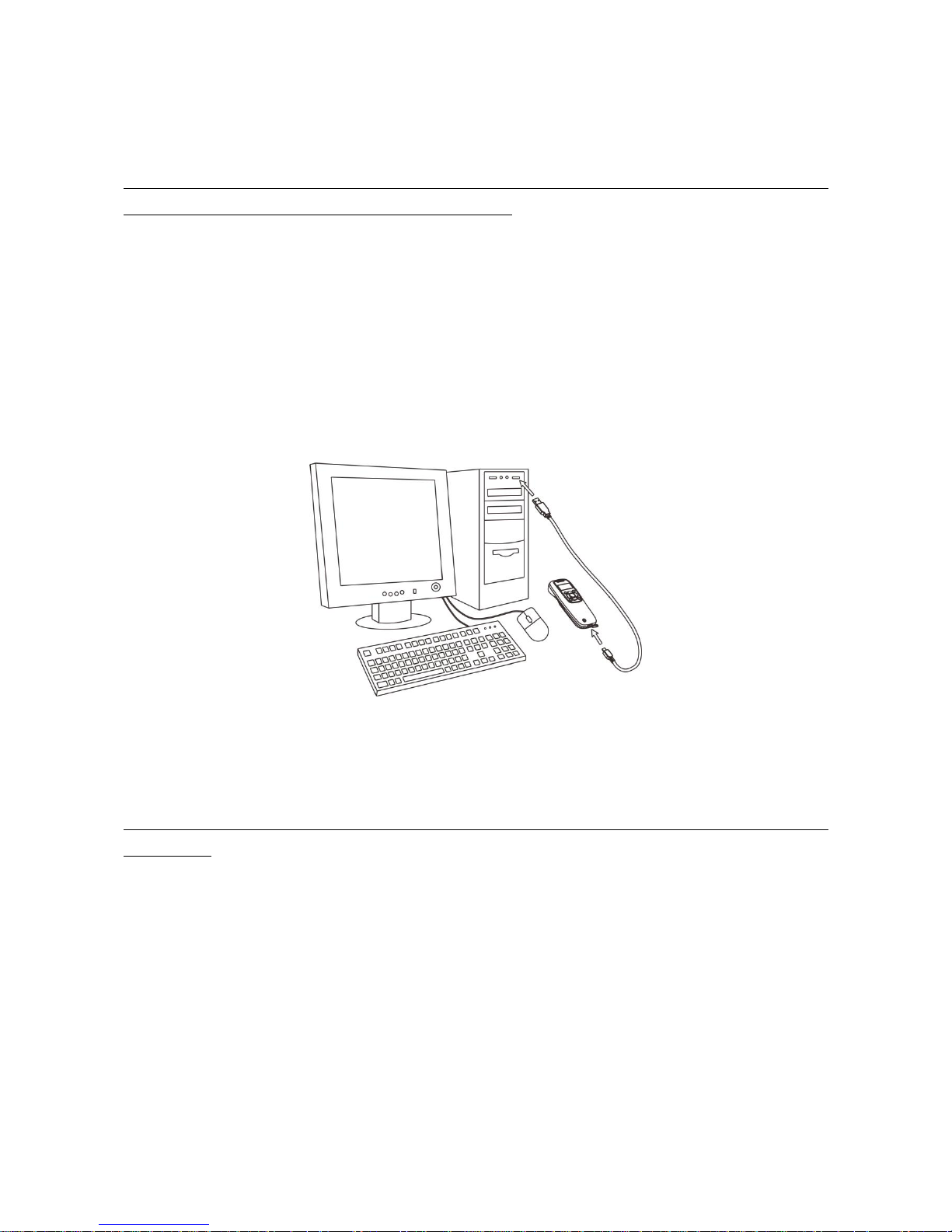
2-1 Installing a USB HID keyboard wired terminal
Note: The default interface of the terminal is BT HID Keyboard. Please change the interface to USB HID
Keyboard (See See Data TransferUSB HID Keyboard).
1. Refer to Figure 2-1, plug one end of the USB cable to the terminal. Plug the other end into the USB
port of the computer.
2. For example: Using Microsoft Windows operation system, the system gives message on “new
hardware found – USB HID input device found”, then driver will be installed on request.
3. After successfully installing the new hardware, message will be given: “hardware installed
successfully and ready to use”.
4. If any problem is encountered during the installation process, unplug the USB cable from the
computer and repeat step 1-2.
Figure 2-1. Diagram of connecting the terminal to PC
2-2 Installing a USB virtual COM wired terminal
Note: The default interface of the terminal is BT HID Keyboard. Please change the interface to USB
Virtual COM.
1. Refer to Figure 2-1, plug one end of the USB cable to the terminal. Plug the other end into the USB
port of the computer.
2. For example: Using Microsoft Windows operation system, the system gives message on “new
hardware found – USB Virtual COM found” for USB virtual COM, then driver will be installed on
request.
3. After successfully installing the new hardware, message will be given: “hardware installed
successfully and ready to use”.
4. If any problem is encountered during the installation process, unplug the USB cable from the
computer and repeat step 1 to step 2.
Page 17
10
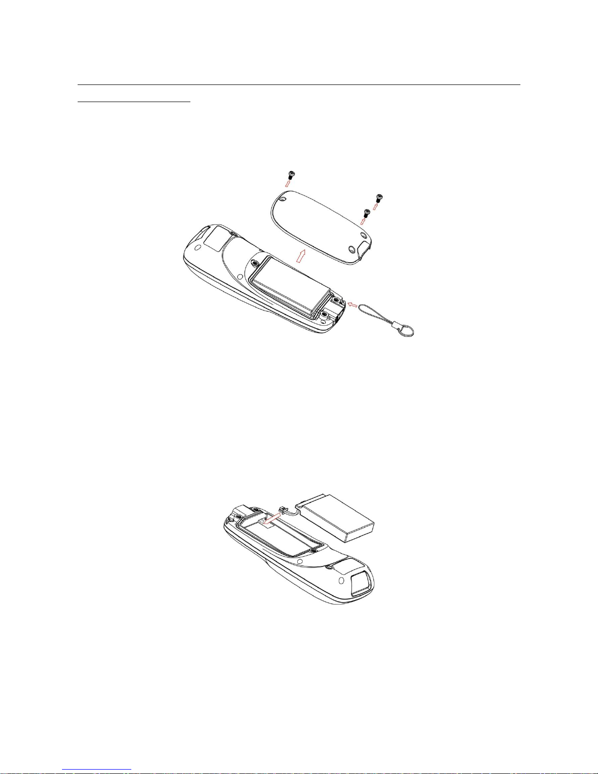
2-3 Attaching the neck/wrist strap
Note: The neck/wrist strap protects the terminal from being damaged as a result of it being dropped by
mistake during movement.
1. Refer to Figure 2-2, remove the 3 screws from the battery cover (one at a time).
2. Attach the neck/wrist strap by hanging the strap ring around the raised part at the corner.
3. Screw in the 3 screws to tighten the terminal and the battery cover.
Figure 2-2. Diagram of attaching the neck/wrist strap
2-4 Replacing the Lithium-ion battery
1. Refer to Figure 2-2, remove the 3 screws from the battery cover (one at a time).
2. Refer to Figure 2-3, load the battery while sliding it with the connection on the battery pack on the
terminal body.
3. Re-place the battery cover, screw in the 3 screws to tighten the terminal and the battery cover.
Figure 2-3. Diagram of replacing the Lithium-ion battery
Page 18
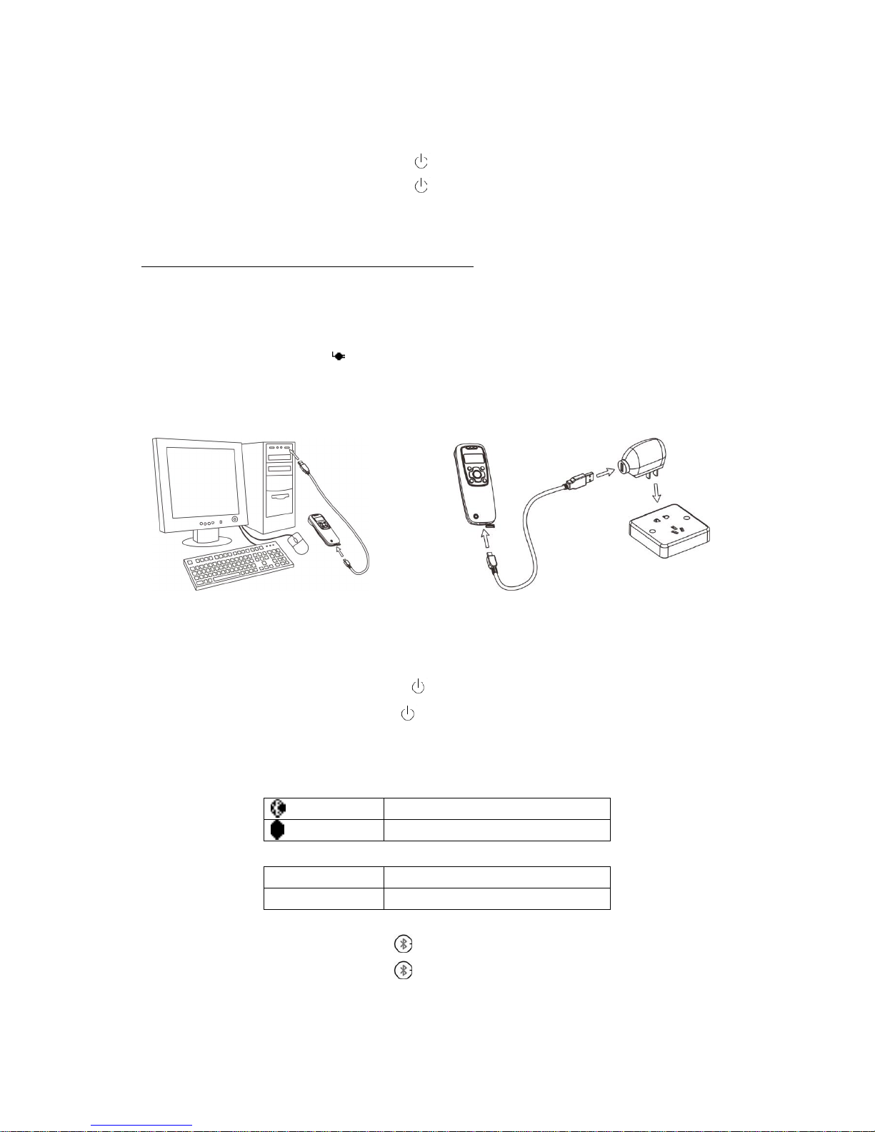
11
3 Getting started
3-1 Power on/off terminal
Power on terminal: Press the Power/Sleep key (see
1-5 Parts of the terminal
) for two seconds.
Power off terminal: Press the Power/Sleep key for two seconds.
3-2 Charge battery
1. Please charge the battery before the first time of use. There are two methods of charging battery as
demonstrated in Figure 3-1. The charging indicator (red LED) on the terminal is turned on when the
charging is in process. When the charging process completes, the red LED is turned off.
2. Charging time: 3.5 hours for fully charged.
3. In scanning status, the icon is seen at the top of the screen display when the terminal is
connected to a PC with the USB cable.
Method I
Method II
Figure 3-1. Diagram of charging battery
3-3 Enter/Exit sleep mode
Enter sleep mode: Press the Power/Sleep key (see
1-5 Parts of the terminal
○12 ) for 0.5 seconds.
Exit sleep mode: Press the Power/Sleep key for 0.5 seconds.
3-4 Power on/off Bluetooth
Bluetooth indicator: In scanning status, the status of the Bluetooth is shown by icons.
Bluetooth is on.
Bluetooth is off.
The status of the Bluetooth is also indicated by the blue LED.
on
Bluetooth is on.
off
Bluetooth is off.
Power off Bluetooth: Press the Bluetooth key (see
1-5 Parts of the terminal
○
11 ).
Power on Bluetooth: Press the Bluetooth key .
Page 19
12
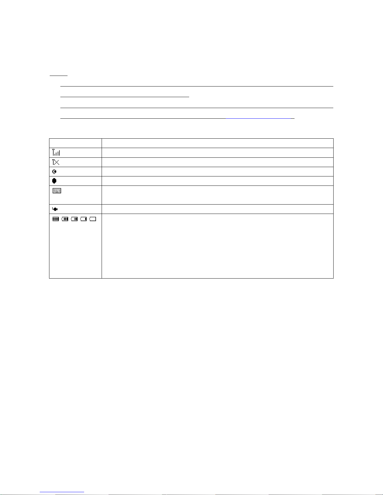
4 Introduction to LCD display
4-1 LCD display icons
Notes:
1- The LCD screen is designed to display barcode scanning, Bluetooth network establishing, data
transfer, system setting and other information.
2- The display area is 64 dots (V) by 128 dots (H). The backlight will be switched off automatically if
time of no operation exceeds a programmable duration (see
5-4-4 Backlight Timeout
).
Table 4-1. LCD display icons
Icon
Description
Bluetooth network is working.
Bluetooth network is disconnected.
Bluetooth module is on.
Bluetooth module is off.
Support for switching among the input of barcode scanning and the virtual keyboard on
Apple iOS, such as Apple ipad.
Terminal is connected to a PC (or other instrument) with USB cable.
Battery capacity (from the left):
• Battery is fully charged (100% - 75% charge remains).
• 75% - 50% charge remains.
• 50% - 25% charge remains.
• 25% - 10% charge remains.
• 10% - no charge remains. When the battery capacity is lower than 10%, the battery
icon blinks and an error tone sounds once every minute.
Page 20
13
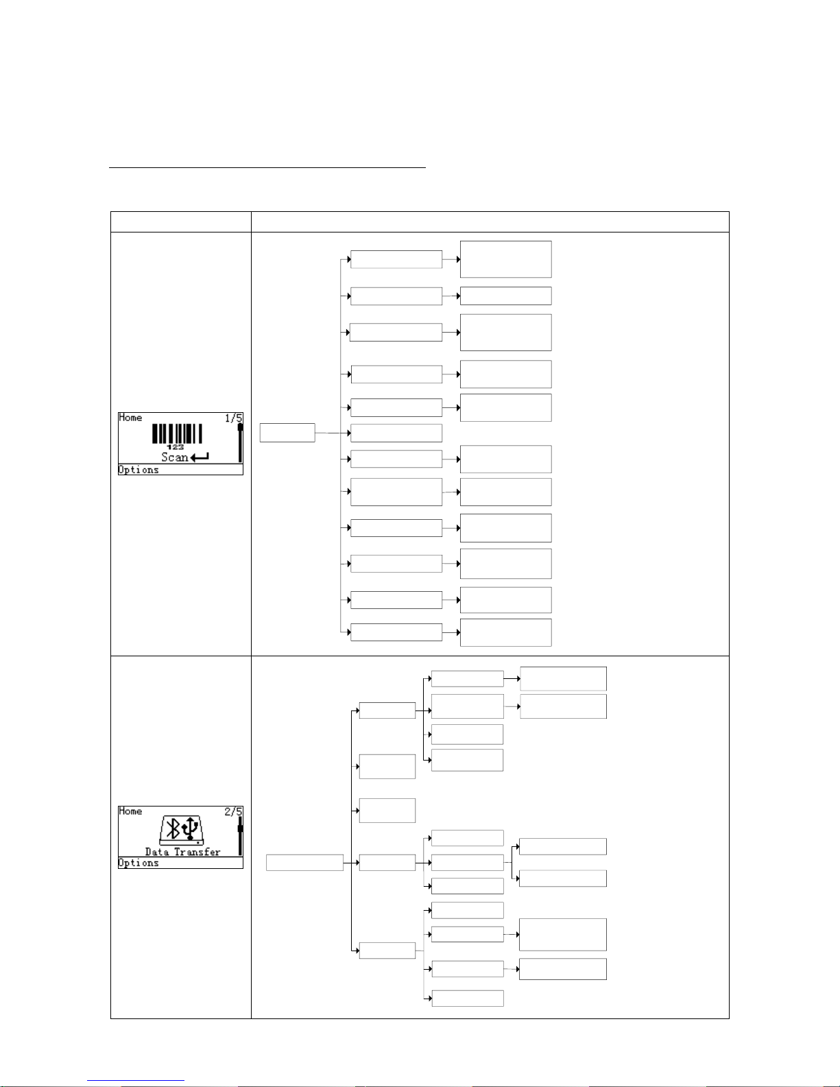
4-2 LCD display menu
The Home menu consists of five items, which are described in details in the following chapters. Table
4-2 depicts the hierarchy chart of the LCD display menu.
Note: Items that are labeled ‘*’ are default selections.
Table 4-2. LCD display menu
Menu
Hierarchy chart
1. Good-read off *
2. Momentary
3. Continuous
Scan
Quantity Enter
Scan Mode
Add Time
1.Disable*
2.Enable
1.Disable*
2.Enable
1.Disable*
2.Repeat Output
3.Output Quantity
Database Query
1.Disable*
2.Enable
Avoid Duplication
1.Disable*
2.Enable
Transfer Confirm
1.Disable*
2.Enable
Set Separator
Input Data Manually
Send
Add Date
Sum Total
Barcode Statistics
1.Disable*
2.Enable
1.Disable*
2.Enable
List File
1.Empty File
2.Delete File
List Files
Create New File
Format
Empty File
Delete File
Interface
Send Batch Data
1.Bluetooth*
2.USB HID Keyboard
3.USB Virtual COM
Date Statistics
1.Disable*
2.Enable
Data Transfer
USB HID
Keyboard
USB Virtual
COM
Bluetooth*
U-Disk
Data Batch
Auto
Reconnection
Out of Range
1.Disable*
2.Enable
1.Disable*
2.Enable
Inter-character
delay
BA2110 Connect
Time
Add Separator
Page 21
14
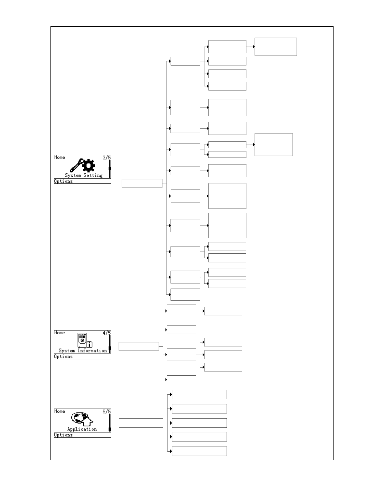
Menu
Hierarchy chart
System
Password
BackLight
Timeout
Sleeping
Timeout
Beeper
Volume
Vibrator
Time and
Date
Default
Setting
Language
1. English *
2. Chinese
1. Disable *
2. Enable
1. 10s
2. 30s*
3. 60s
4. Off
1. 1min
2. 5min*
3. 10min
4. Off
Bluetooth
BT HID
Keyboard *
BT SPP Slave
BT SPP Master
1. USA*
2. French
3. ...
USB HID
keyboard
1. USA*
2. French
3. ...
System Setting
1.Time
2.Date
BA2110
1. Volume
2. Key Tone
1. Low
2. Middle*
3. High
4. Off
Terminal
2. BA2110
System Information
Terminal
Scan Engine
Bluetooth
Firmware
Version
Help
Bluetooth
View
Memory
Erase
Application Download
Installation Key
Execute
Auto Run
Verification Code
Page 22
15
5 Operations of the terminal
Note:
1. Please establish a Bluetooth network and hold the terminal in the range of the network before the
first time of scanning barcodes (See
5-3-2 Configure Bluetooth HID keyboard profile communication
,
5-3-3 Configure Bluetooth SPP slave profile communication, 5-3-4 Configure Bluetooth SPP master
profile communication
).
2. The terminal can perform a barcode scan operation even though no Bluetooth network is available.
However, the terminal may react in a way that differs from what is described here if no Bluetooth
network is working.
5-1 Scan
Steps:
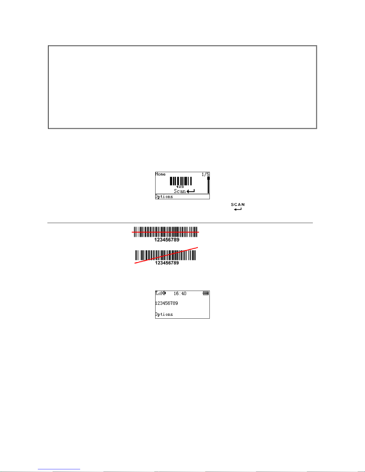
Step 1: When the terminal is powered on, the LCD screen is displayed as below.
Step 2: Hold the terminal close to the barcode and press the Scan Key .
Note: When the terminal is scanning, ensure the scan line crosses every bar and space of the symbol.
RIGHT
WRONG
Step 3: The terminal port emits a laser to scan the barcode. The decode success indicator lights green
when the scan is successful. The window will show as below.
5-1-1 Scan Mode
Good-read off - The Scan key must be pressed once to activate scanning. The light source of terminal
stops scanning when there is a successful reading or no code is decoded after the Stand-by duration
elapsed.
Momentary - The Scan key acts as a switch. Press the key to activate scanning and release the key to
stop scanning. The light source of terminal stops scanning when there is a successful reading or no code
is decoded after the Stand-by duration elapsed.
Continuous - The terminal always keeps scanning, and it does not matter when the Scan key is released
or duration is elapsed.
Page 23
16
5-1-2 Input Data Manually
Using the virtual keypad, user can input a barcode manually, and then send the barcode to the host or
store in the terminal.
Make sure a communication link (Bluetooth network or USB cable) is working.
5-1-3 Quantity Enter
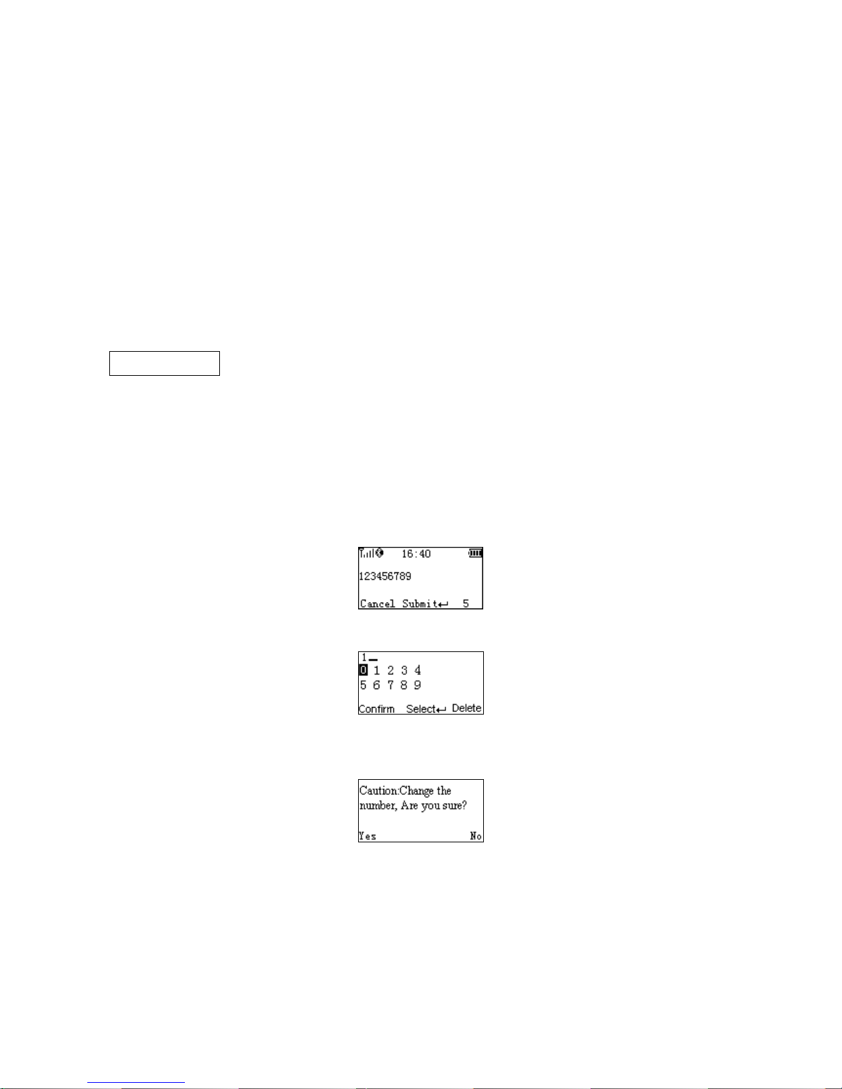
User can disable the Quantity Enter and select Repeat Output mode or Output Quantity mode. When
Quantity Enter is enabled, user can set the number (0 to 9999) of barcode transmissions. For example, a
barcode “123456789” is read. When user select Repeat Output mode, Five “123456789” will be received
by the host, given that the quantity is 5. When user selects Output Quantity mode, “123456789, 5” will be
received by the host, given that the quantity is 5. The quantity decides how many identify barcodes a
host receives upon a single successful read.
Separator Setting- When user selects Output Quantity mode, the barcode and quantity will be
separated, the default separator is comma <,>. Separator Setting is Quantity enter-Output
Quantity-Options. By using the virtual keypad, user can input character manually. The length of the
separator string can be at most 10 characters.
The following steps demonstrate the procedure to set a quantity.
Step 1: Enable Quantity Enter, press the Scan Key to read a barcode.
Example display:
Step 2: Press Right Soft Key to the window below.
Step 3: Use Navigation Keys to move the cursor, Scan/Select Key to select number(s), Right Soft Key to
delete selected number(s). And then press Left Soft Key to continue.
Step 4: Finally press Left Soft Key to complete.
Page 24

17
5-1-4 Add Time
The time/data information can be added as an appendix to a barcode by enabling the Add Time.
For example:
When Add Time is enabled, a barcode “123456789” is read in 12:00:00, “123456789,12:00:00” will be
received by the host.
When Add Time and Add Date is enabled, a barcode “123456789” is read in 12:00:00 at 25.05.2012,
“123456789,12:00:00, 25.05.2012”will be received by the host.
5-1-5 Add Date
The time/data information can be added as an appendix to a barcode by enabling the Add Date.
For example:
When Add Date is enabled, a barcode “123456789” is read at 25.05.2012, “123456789, 25.05.2012” will
be received by the host.
When Add Time and Add Date is enabled, a barcode “123456789” is read in 12:00:00 at 25.05.2012,
“123456789,12:00:00, 25.05.2012” will be received by the host.
5-1-6 Set Separator
The barcode and Time/Data/quantity will be separated by separator, the default separator is comma
<,>. By using the virtual keypad, user can input character manually. The length of the separator string
can be at most 10 characters.
Example1: A barcode “123456789” is read in 12:00:00 at 25.05.2012. When user selects Output
Quantity mode, “123456789, 5” will be received by the host, given that the quantity is 5.
123456789,5,12:00:00,25.05.2012
Example2: When user enables the Data Statistics, the barcode and quantity will be separated, the eighth
barcode is “123456789” in the example below.
123456789,8
5-1-7 Database Query
Database query includes: After successfully scanning the barcode, the barcode information would be
displayed on the LCD screen. The database query function demands the use of MS3 DB database
supporting software tool to generate database files: *.IDX and *.DAT. By applying the database query
functionality, the user can rapidly and accurately locate the barcode information.
When user scan the barcode, the terminal would perform a database searching upon the database files
stored in the flash disk and display the barcode information if matching is found when the database
query function is enabled. User would require scrolling to left or right for more information displayed on
the LCD screen. If no matching is found then “No Record” is displayed on the LCD screen.
Example:
User barcode information as follows:
Page 25

18
A B C D 1 Barcode
Trade Name
Price
Place of Production
2
12345670
Computer
¥3000.00
Shenzhen
When user scan the barcode “12345670”, The terminal would display “Computer, ¥ 3000.00,
Shenzhen” on the LCD screen.
Note: The default database files are named SYS_DB.IDX and SYS_DB.DAT. In order to utilize the
database functionality user should NOT change these file names and these two files are properly stored
to the flash disk.
5-1-8 Avoid Duplication
When user scans the barcode, the terminal retrieves the database for a match in the meantime. If the
barcode does not exist in the database, the barcode will be recorded into the database file, sent out or
stored in USB Disk. Neither transmission nor store operation will be performed if a barcode already
exists in the database. Furthermore, the “Barcode already exists” message is displayed on the LCD
screen.
User can clear the previous barcode record by entering the same barcode avoidance setting menu page
and pressing the left soft key (clear).
5-1-9 Barcode Statistics
The terminal will automatically count and display the number of barcodes which have been sent or
stored successfully when Barcode Statistics function is enabled.
User can clear the previous barcode record by entering the barcode statistic function setting menu page
and pressing the left soft key (clear).
5-1-10 Sum Total
The terminal will automatically count and display the number of the whole barcodes which have been
sent or stored successfully when Barcode Statistics function is enabled.
User can clear the previous barcode record by entering the barcode statistic function setting menu page
and pressing the left soft key (clear).
5-1-11 List Files
This menu can be selected to list all files in the root directory. The file selected to be the target file is
labeled √. The operations described below are imposed to the cursor-on file, which is not necessary to
be the target file.
Example:
Page 26

19
Options Menu
Note: Press Left Soft Key to popup this menu.
Caution:
Empty and Delete operations are not undoable. It is strongly recommended to back up
the data before empty or delete operation.
Empty/Delete Files
If the U-disk is almost full, occupied room can be released by emptying/deleting some files.
A target file is protected by system and prevented from being deleting. In this case, the file that is wanted
to be deleted should be deselected and then deleted.
5-1-12 Transfer Confirm
User can select to enable/disable the transfer confirm. When the scan is successful,The terminal
would point out that whether confirm to transfer this barcode. User can press left soft key to cancel
transfer or press right soft key to confirm transfer barcode data.
Page 27

20
5-2 Data Transfer
5-2-1 Bluetooth
See
5-3 System Setting - Bluetooth
for instructions to establish a Bluetooth network. Three options are
listed below.
Out of range batch- The terminal starts storing barcode data when it loses its connection to a remote
host (for example, when a user holding the terminal walks out of range). Data transmission is triggered
by reestablishing the connection with the host (for example, when a user holding the terminal walks back
into range).
Auto reconnection- When terminal’s Bluetooth is power on, it will try to establish the wireless connection
with the host which it last connected, if Auto Reconnection is enabled.
Inter-char delay- Inter-character delay is abbreviated to Inter-char delay. This delay is inserted after each
data character transmitted when configure Bluetooth to HID keyboard profile. Some Bluetooth
communication needs large delay to avoid data missing. This default delay is set to 8 milliseconds.
BA2110 Connect Time- This is a standby time for the user to plug the BA2110 into PC after scanned the
barcode on the back of BA2110. The default standby time is set to 10 seconds. (For more detail, please
refers to
5-3-6 Configure the profile of BA2110
).
5-2-2 USB HID Keyboard
When the terminal is USB connected to a PC, it will be identified as a USB HID keyboard and behaves
as a USB wired terminal.
5-2-3 USB Virtual COM
When the terminal is USB connected to a PC, it will be identified as a USB Virtual COM and acts as a
RS-232 wired terminal.
5-2-4 U Disk
Barcode data is always stored in a text file (TXT file), that is, the terminal functions as a barcode data
collector. The terminal will be identified as a USB removable driver when it is USB connected to a PC.
The terminal decides target file to store barcodes according to following rules:
If a file is selected by the user, the selected file will be the target file.
If there is no file in the U-Disk, a file will be created and named “TARGET.txt” by the terminal when it
is powered on or restart. In this case, TARGET.txt will be the target file.
The file selected to be the target file is labeled √.
1) Create New Files
Note:
1. Files can be opened/edited/saved/renamed/deleted by the user of a PC and
created/emptied/deleted by the user of a terminal.
2. A valid filename, not including the suffix, is composed of up to 8 characters from three groups:
Upper case letters “A”–”Z”, Numbers 0–9 and special sign ! # $ % & ' ( ) - @ ^ _ ` { } ~ .
Page 28
21
3. Only part of the filename will be displayed if there are more than 8 characters in a filename. e.g.
“TextFile1Mine.txt” will be shown as “TEXTFI~1.TXT”
4. Lower case is not supported and “a”-”z” will be displayed as “A”-”Z” respectively for a filename.
e.g. “ABCabc.txt” will be shown as “ABCABC.TXT”.
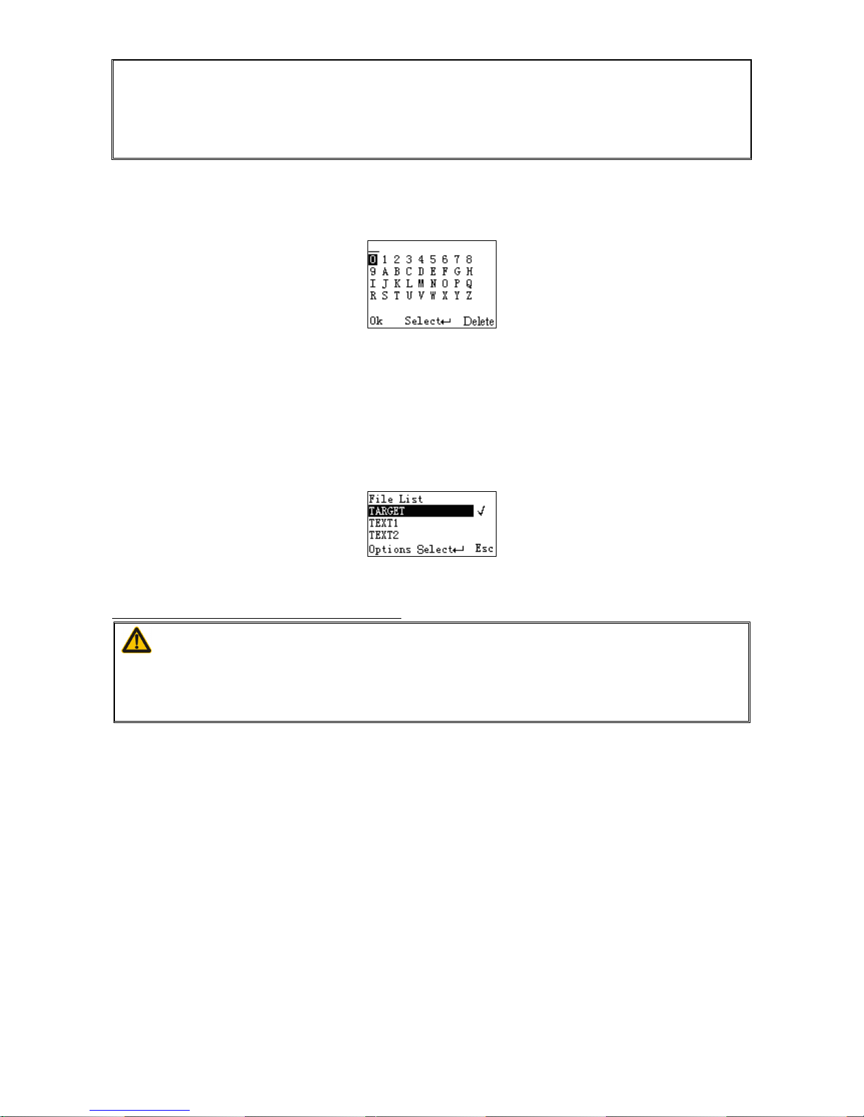
When a file is created, the filename can be input by using the virtual keyboard. Use Navigation Keys to
move the cursor, Scan/Select Key to select number(s), Right Soft Key to delete selected number(s). And
then press Left Soft Key to complete.
2) List Files
This menu can be selected to list all files in the root directory. The file selected to be the target file is
labeled √. The operations described below are imposed to the cursor-on file, which is not necessary to
be the target file.
Example:
Options Menu
Note: Press Left Soft Key to popup this menu.
Caution:
Empty and Delete operations are not undoable. It is strongly recommended to back up
the data before empty or delete operation.
3) Empty/Delete Files
If the U-disk is almost full, occupied room can be released by emptying/deleting some files.
A target file is protected by system and prevented from being deleting. In this case, the file that is wanted
to be deleted should be deselected and then deleted.
Page 29
22
4) Format a U Disk
Note 1: The format function is a quick way to empty a whole U Disk.
Note 2: Please format the U Disk once before the first time of use.
Caution:
1. Format operation will erase all data on the disk.
2. Format operation is not undoable. It is strongly recommended to back up the data
before format operation.
5) Data batch
The terminal starts storing barcode data in Date Batch mode. The collected barcode data can then be
sent to a host via Bluetooth/USB. Three options are listed below.
Send batch data- Data transmission is triggered by this menu command. Before undertaking this
operation, make sure a communication link (Bluetooth network or USB cable) is working.
Interfaces- There are three types of communication interfaces Bluetooth, USB HID keyboard and USB
virtual COM. A Bluetooth link is needed in the first case (See
5-3 System Setting - Bluetooth
).
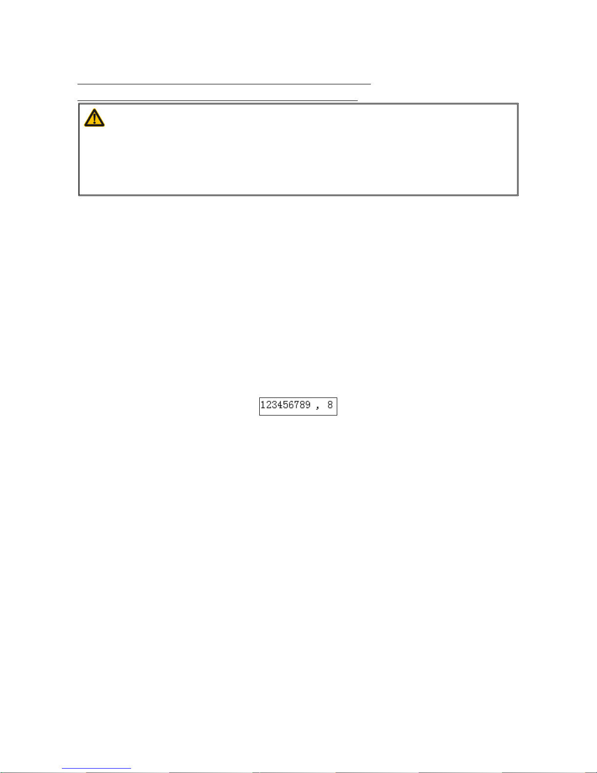
Data statistics- User can select to enable/disable the Data Statistics. When it is enabled, the number of a
barcode would be added to the end of the barcode. The eighth barcode is “123456789” in the example
below.
Example:
Page 30
23
5-3 System Setting - Bluetooth
5-3-1 Bluetooth Functionalities
The terminal can be configured to send data to a PC/Notebook/PDA/other instrument which has an
integrated Bluetooth module or is connected with an external Bluetooth USB adapter. A diagram of
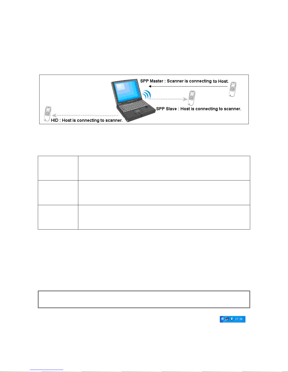
Bluetooth functionalities and a table of various Bluetooth profiles are shown below, respectively:
Figure 5-1. Diagram of Bluetooth functionalities
Table 5-1. Various Bluetooth profiles
HID Keyboard
The terminal connects to the PC/host via Bluetooth and behaves like a keyboard.
The terminal accepts incoming connection requested from a remote device and is
the slave.
SPP slave
The terminal connects to the PC/host via Bluetooth and behaves like there is a
serial connection. The terminal accepts incoming connection requested from a
remote device and is the Slave.
SPP master
The terminal connects to the PC/host via Bluetooth and behaves like there is a
serial connection. The terminal initiates the connection to the remote device and
is the Master.
A master SPP mainly differs from a slave one in the process of connection and they are identical in the
process of use in terms of function.
Bluetooth-enabled smart phones and PDAs can host the terminal in general. However, ordinary mobile
phones with Bluetooth function can not be a host of the terminal because in most cases neither HID nor
SPP profile is supported by them.
5-3-2 Configure Bluetooth HID Keyboard Profile Communication
Note: Make sure the Bluetooth module of the terminal is powered on (blue LED is on) and the
selected profile is System SettingBluetoothBT HID Keyboard.
Step1. Plug a Bluetooth USB adapter into the USB port of the computer.
Step2. Double-click the Bluetooth icon at the right bottom corner on Windows OS ( ).
Alternatively, you may go to Control Panel->Bluetooth Device.
Page 31
24
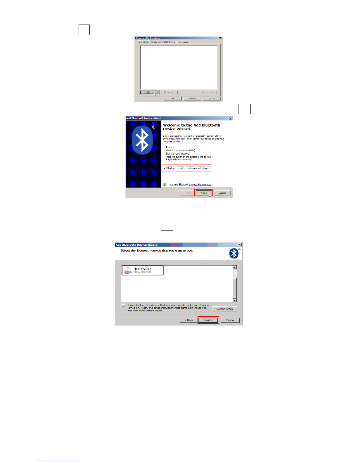
Step3. Click Add to search devices nearby.
Step4. Click to select “My device is set up and ready to be found” and click Next.
Step5. It takes a few seconds for the Wizard to search devices.
The terminal will appear with its serial number as the device name. If the target terminal is seen on the
list, click and select the target terminal. Click Next. If the target terminal does not appear on the list, click
[Search Again] to refresh the list.
Page 32
25
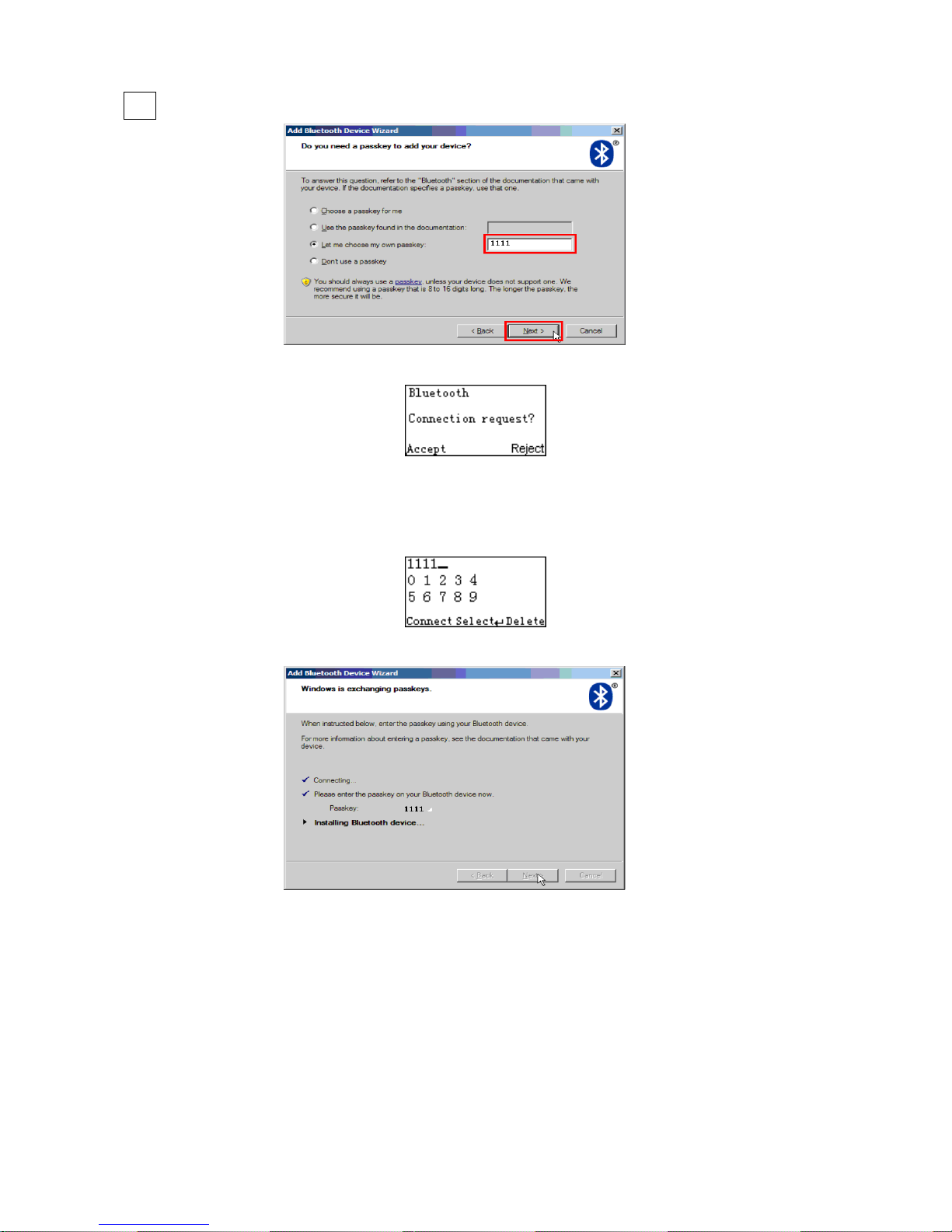
Step6. Click and select “Let me choose my own passkey”. Enter a passkey for authentication and click
Next.
Step7. The terminal promotes the user to accept the connection request. Press Left Soft Key to accept.
Step8. Enter a passkey which is exactly the same as that entered from the PC. Use Navigation Key to
move the cursor, Scan/Select Key to select number(s), Right Software Key to delete selected number.
Finally press Left Software Key to continue.
Step9. Wait for a few seconds for Windows to exchange passkeys.
Page 33
26
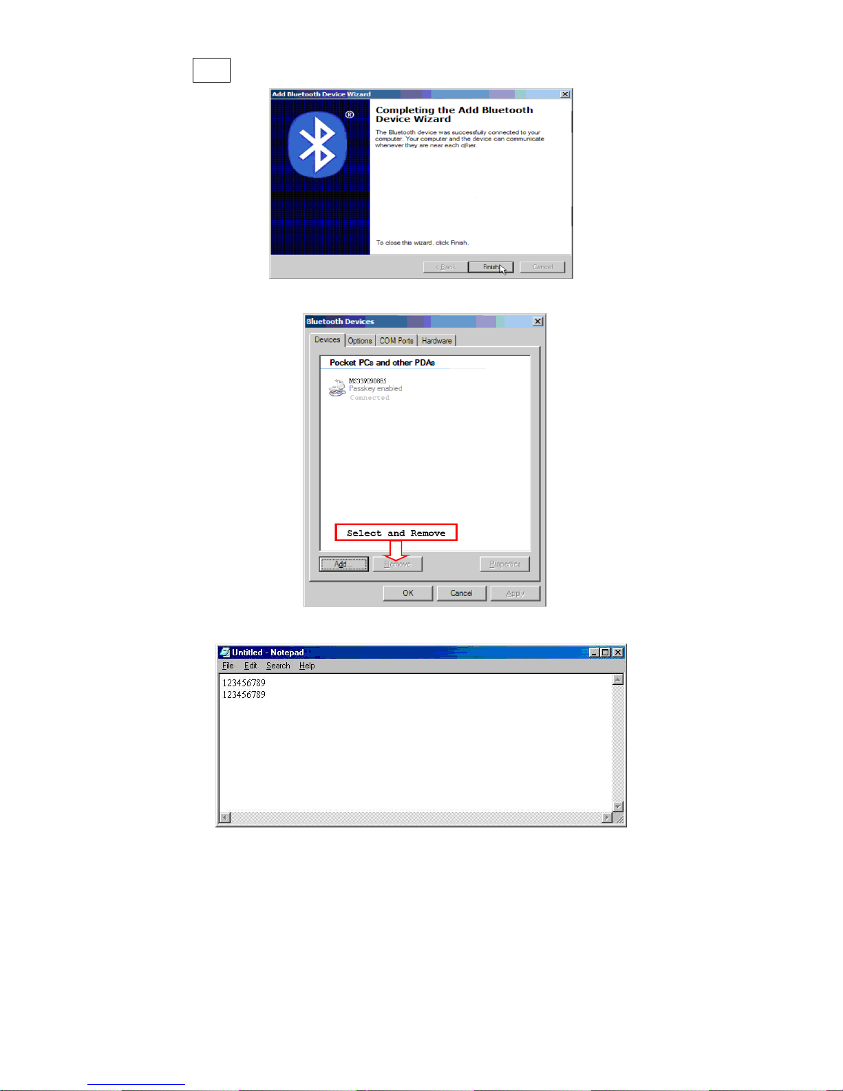
Step10. Click Finish
Step11. Now the target terminal will be listed as shown below.
Step12. Run the desired application, such as a Notepad and scan barcodes to check data transmission.
Page 34
27
5-3-3 Configure Bluetooth SPP Slave Profile Communication
Note: Make sure the Bluetooth module of the terminal is powered on (blue LED is on) and the selected
profile is System SettingBluetoothBT SPP Slave.
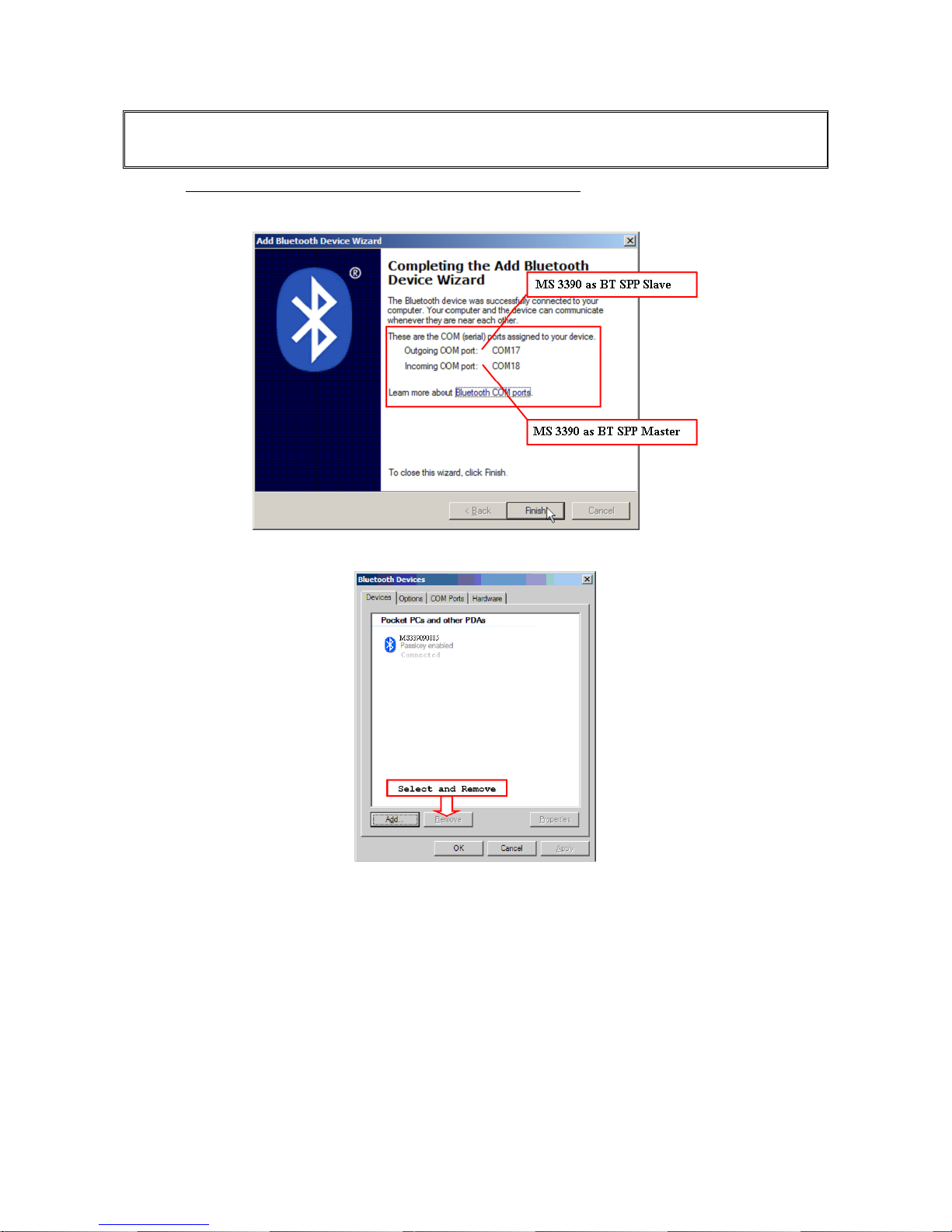
Step1-9: The same as Configure Bluetooth HID keyboard step 1~9.
Step10. Click [Finish]
Step11. Now the target terminal will be listed as shown below.
Page 35
28
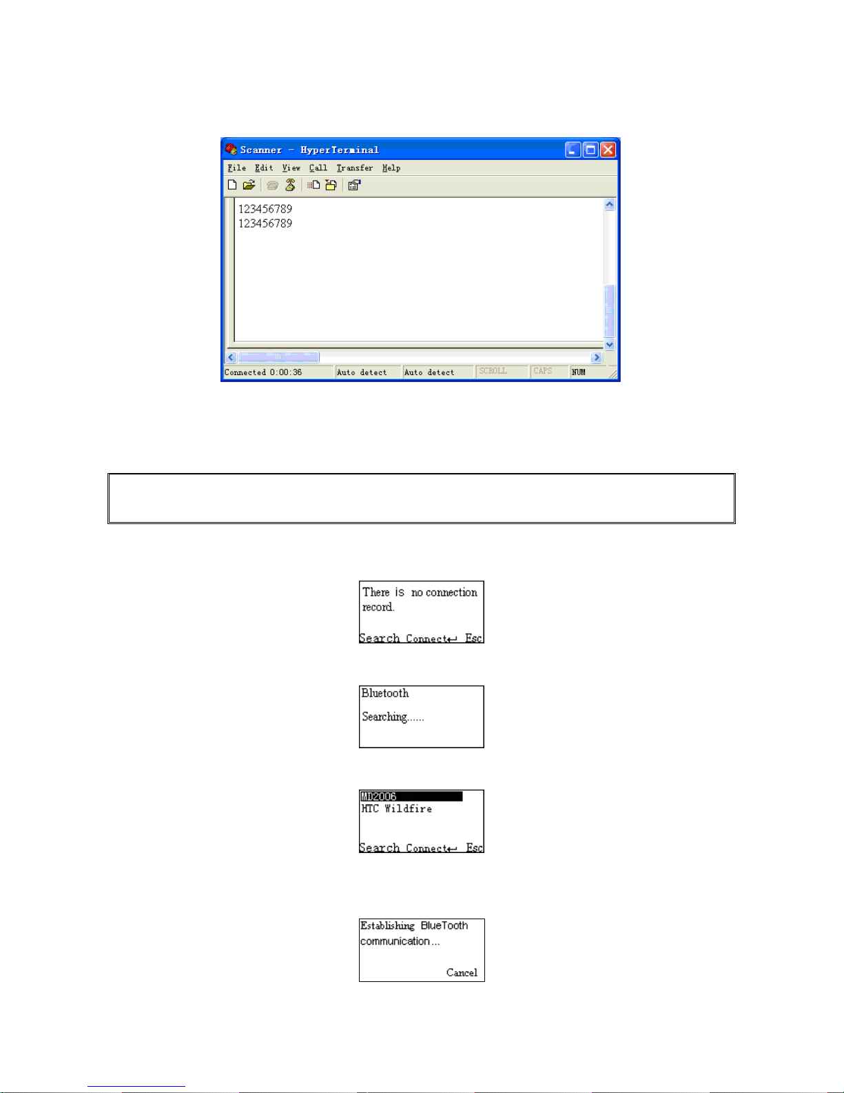
Step12. Run a Serial Port Tool, e.g. HyperTerminal on your computer. This step guarantees the terminal
to complete establishing Bluetooth communication. And then scan a barcode to confirm the success of
data transmission.
5-3-4 Configure Bluetooth SPP Master Profile Communication
Note: Make sure the Bluetooth module of the terminal is powered on (blue LED is on) and the selected
profile is System SettingBluetoothBT SPP Master.
Step1. Press Left Soft Key to the window below. If the terminal has no connection record, it will show the
indication” There is no connection record.”
Step2. Press Left Soft Key to the window below for searching.
Step3. Wait for about 20 seconds and then the devices list will be shown.
Step4. Use Navigation Key to move the cursor and press Scan/Select Key to connect to the Bluetooth
USB adapter.
Page 36
29
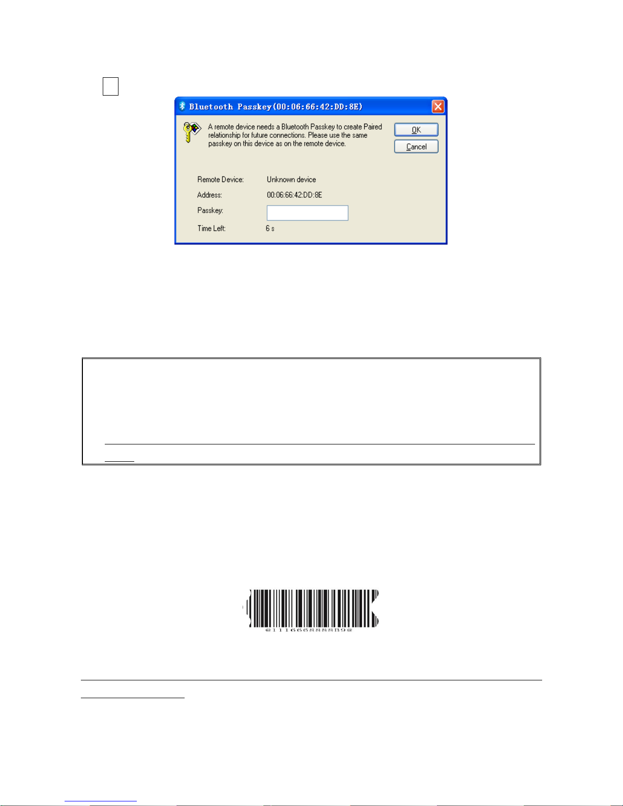
Step5. The remote device will promote user to accept the connection request, and then user enters the
passkey. The default passkey of the Bluetooth module of the terminal is “0000”. So enter “0000”, and
click OK.
Step6. The Bluetooth device connected to the terminal is labeled √.
Step7. If you want to disconnect the Bluetooth device connected successfully before, you can press
Scan/Select Key to disconnect it.
5-3-5 Configure Bluetooth USB Adapter BA2110
Notes:
1. BA2110 is provided by the manufacturer to support reliable wireless data transmission and is
advised in applications whereas unacknowledged communication is unacceptable.
2. Make sure the Bluetooth module of the terminal is powered on (blue LED is on)
3. By default, the profile of the BA2110 is “USB HID keyboard”. An alternative option is “USB virtual
COM”.
There are two methods to setup the Bluetooth communication.
Method I: scanning special barcode.
There is a barcode on the back of BA2110 as shown below. Scan the barcode. The terminal will beep
twice to indicate a successful scan. Please plug the BA2110 into PC within BA2110 Connect Time, and
then wait for about 5 seconds. The terminal will give 2 long beeps upon a successful connection, or 3
short beeps upon a failed connection.
An example of barcode to indicate a BA2110
Note: For more information of the BA2110 Connect Time, please refer to 5-2 Data transfer-BluetoothBA2110 Connect Time.
Page 37
30
Method II: operating the terminal on the LCD screen.
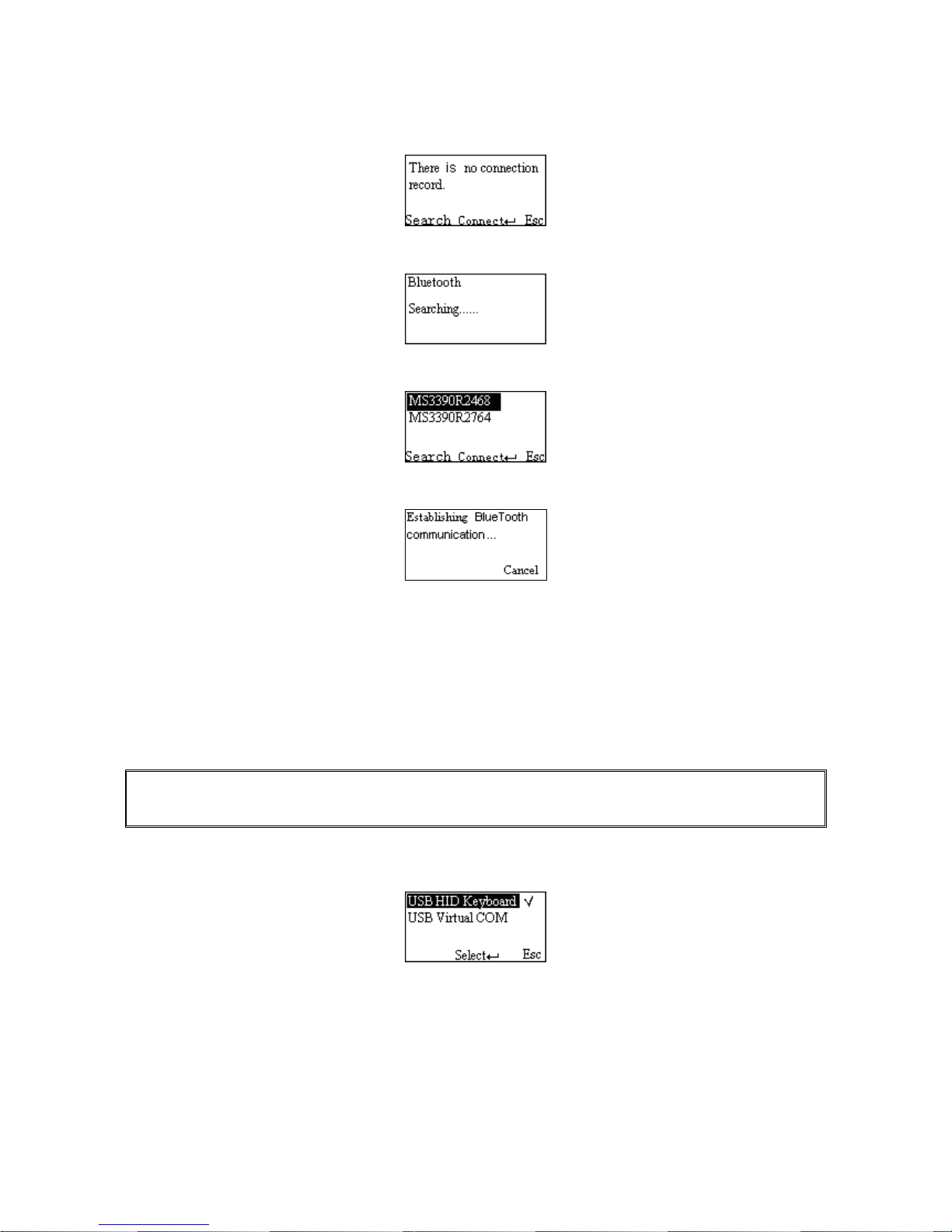
Step1. Press Left Soft Key towards the window below. If the terminal has no connection record, it will
show the indication of “There is no connection record.”
Step2. Press Left Soft Key to the window below for searching.
Step3. Wait for about 20 seconds and then BA2110 list will be shown.
Step4. Use Navigation Key to move the cursor and press Scan/Select Key to connect with BA2110.
Step5. Wait for about 3 seconds, the terminal will respond with 2 long beeps upon successful
connection.
Step6. The BA2110 connected to the terminal is labeled √.
Step7. If you want to disconnect the BA2110 connected successfully before, you can press Scan/Select
Key to disconnect it.
5-3-6 Configure the Profile of BA2110
Note: Before the configuration, make sure the terminal is wireless-connected with the BA2110
successfully.
Step1. Press Left Soft Key to the window below.
Step2. Use Navigation Key to move the cursor and press Scan/Select Key to select items.
USB HID Keyboard
Keyboard layout: The BA2110 supports different national keyboard layouts.
Comm. port speed: By selecting, the user can change the output speed of the BA2110 to match the
speed of the host USB communication port. Generally, the default setting is high communication speed
mode. If some output characters of barcode have been missed, the user may need to set slow or middle
Page 38

31
mode to slow the data transmission speed of the terminal.
Numeric key:
Alphabetic key- the terminal will output code result as alphabetic key.
Numeric key- the terminal will output code result as pressing numeric keypad ( ‘0’, ‘1’, ‘2’, ‘3’, ‘4’, ‘5’, ‘6’,
‘7’, ‘8’, ‘9’, ‘.’, ‘+’, ‘-‘, ‘/’, ‘*’ only).
Alt+ keypad- the terminal will output code result as pressing Alt+ numeric key (on keypad). Note that
the Num Lock control key must be ON. This setting can be specially adapted for use with different
national keyboard layout.
Page 39

32
5-4 System Setting - General
5-4-1 Language
This option is used to select a language for menu display.
5-4-2 Volume of Beeper
1) Volume
This option is used to control the beeper volume.
2) Keystone
This option is used to turn on/off the Keystone
5-4-3 Vibrator
This option is used to turn on/off the vibrator indicator of a good read.
5-4-4 Backlight Timeout
The terminal will switch off the backlight if time of no operation exceeds Backlight timeout.
5-4-5 Sleeping Timeout
The terminal will enter sleep mode if time of no operation exceeds Sleeping timeout. User can set the
terminal to sleep mode by press Power/Sleep key (see
3-3 Enter/exit sleep mode
and
3-4 Power on/off
Bluetooth
).
5-4-6 Default Setting
Default setting includes the terminal and the BA2110.
1) All parameters of the terminal return to default setting.
Table 5-2 General system setting
Items
Option
Language
English*
Chinese
Beeper volume
Low
Middle
High*
Off
Vibrator
Disable
Enable*
Backlight timeout
10s
30s*
60s
Off
Sleeping timeout
1min
5min*
10min
Off
Page 40

33
2) All parameters of the BA2110 return to default setting.
The profile of BA2110 is USB HID Keyboard, Keyboard layout is USA keyboard layout, Comm. port
speed mode is high speed mode, and Numeric key type is Alphabetic key.
Notice:To set all parameters of the BA2110 to default setting, please make sure the BA2110 and the
terminal are connected properly.
5-4-7 System Password
Application of system password relates to user application (for more detail please refers to
6 User
customized software development
). When this option is enabled, system password is required when
switching from user application state back to system state.
If the user download the user customized application software, and enable the boot settings, the system
is run directly to the user's application when switched on. When user keep pressing the right soft key
during system booting stage, the system password is required before entering the system state. Entering
the system state is only allowed after the correct password is provided. Pressing the return key could
lead to the user customized application software state.
Notice: The default system password of the terminal is “1234”.
Steps for setting the system password:
Step1. Enter the old (previous set) password for verification. Proceed to create new password stage if
correct password is provided, otherwise starts over.
Step2. Enter new password.
Step3. Re-enter the new password for verification.
Step4. If the newly entered passwords are identical then creation of new password is successful.
Page 41
34
5-5 System Information
5-5-1 View Memory
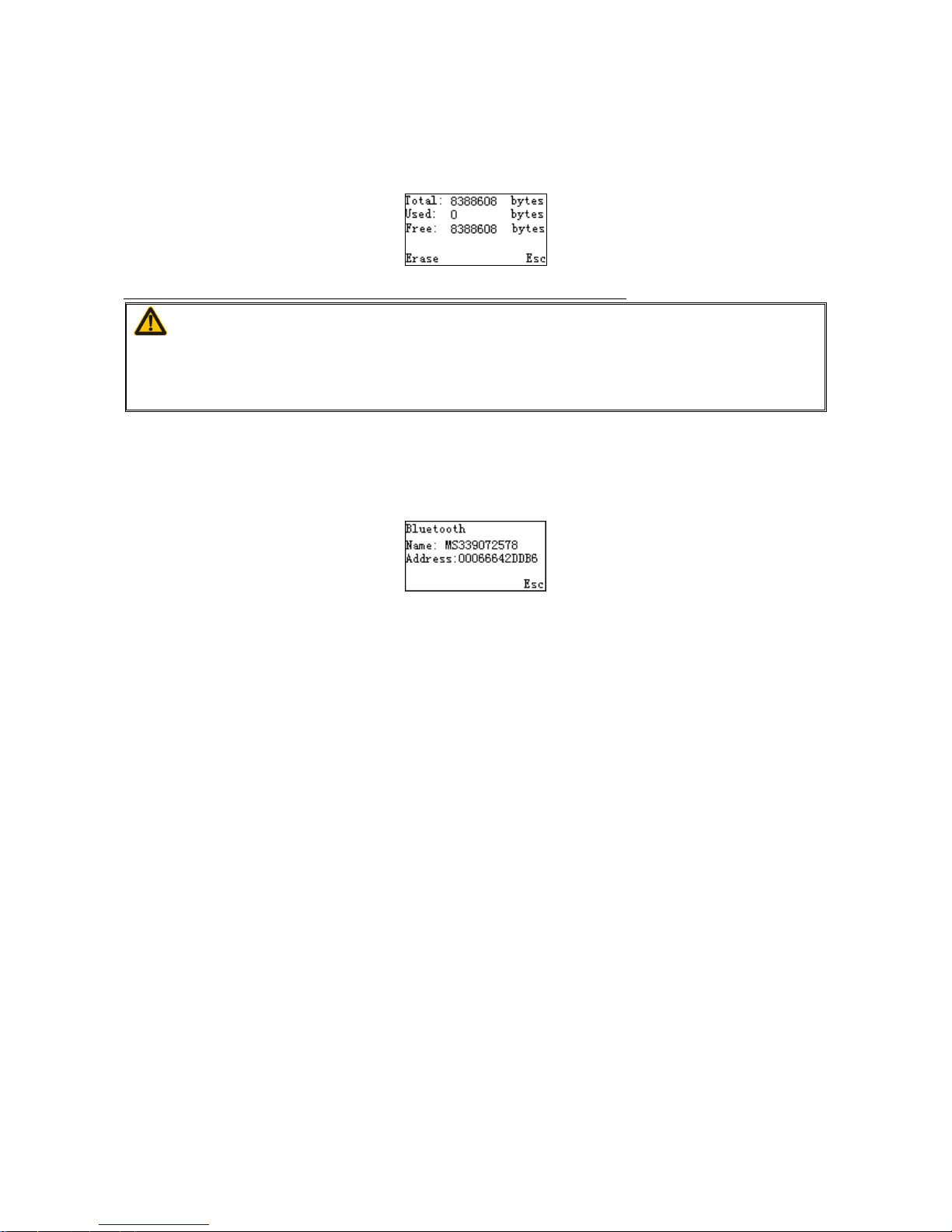
User can view the used and remain memory capacity in Batch Mode.
Note: User can press Left Soft Key to erase data to release used memory.
Caution:
1. Erasing operation will delete all data in the memory.
2. Erasing operation is not undoable.
5-5-2 Bluetooth Module
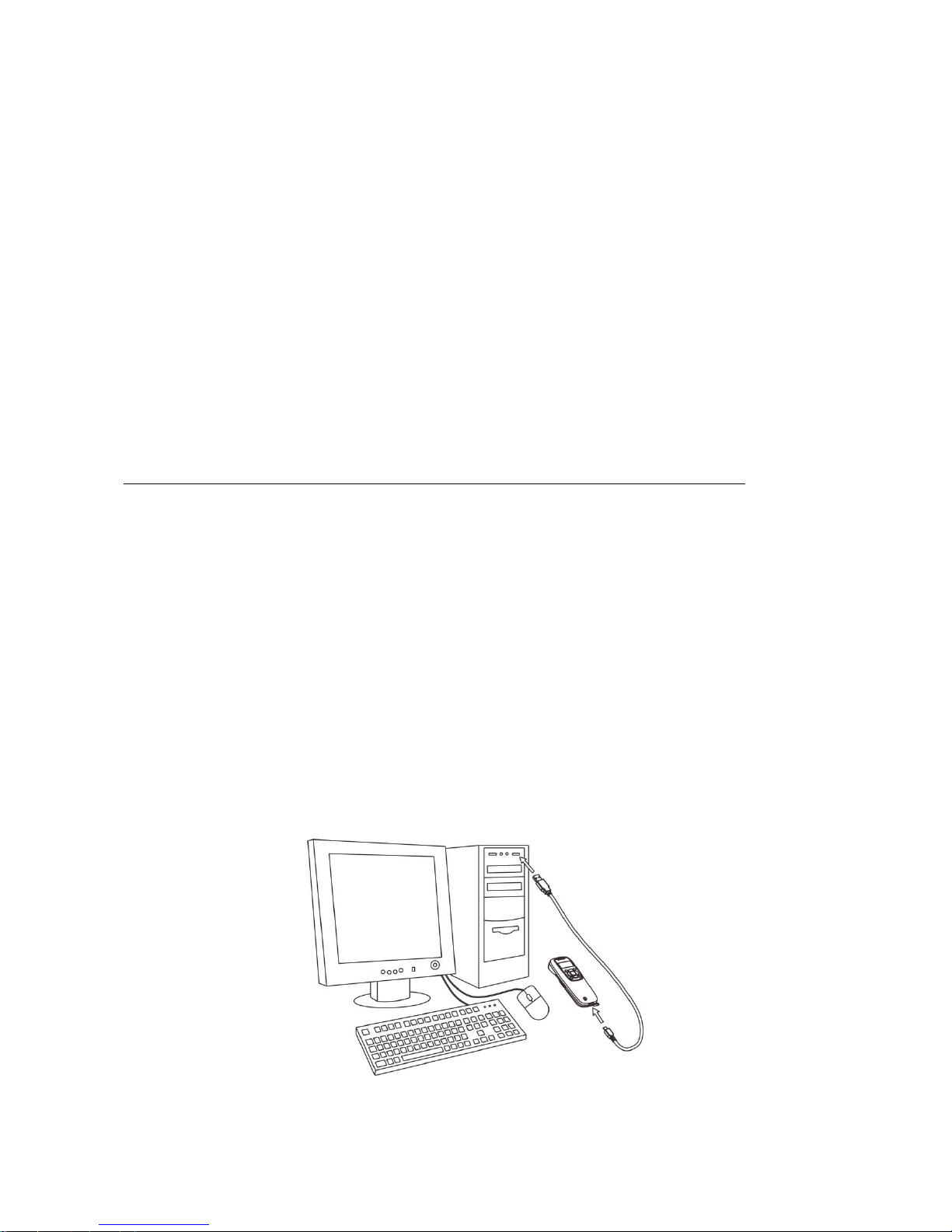
User can view the name and address of the Bluetooth module.
Example:
5-5-3 Firmware Version
User can view the firmware version of the terminal, scan engine, and Bluetooth module.
Page 42
35
6 User customized application software for MS3390
With the support of MS3 SDK, The terminal supports user customized application software development.
User customized application software is developed with the support of the terminal system API. For
more detail about user customized application software development please refer to the MS3 SDK help
files.
User customized application menu in the terminal show as below:
6-1 Auto Run
When this option is enabled the terminal would automatically runs the user customized application
software after boots. When user keep pressing the right soft key during system booting stage, the
system password is required before entering the system state. Entering the system state is only allowed
after the correct password is provided. Pressing the return key could lead to the user customized
application software state. For more information on system password settings please refer to
5-4-7
System password
.
Note: It only works after successfully downloaded the user customized application software.
6-2 Execute
User could execute the user customized application software by entering the “Execute” menu. Please be
sure the user customized application software is properly downloaded to the terminal before execution.
6-3 Delete
User could delete the user customized application software by selecting the “Execute” menu and
pressing the left soft key-”Delete”.
6-4 Download
Enter into this menu to download application by MS3 SDK;
Step1. Power on the terminal, enter into the menu:Application->Download;
Step2. Make sure of connecting the PC and MS3390 well with USB cable;
Page 43

36
Step3. Clicking on the button in the toolbar of MS3 SDK to perform download BIN file or ENP file to
the terminal;
Step4. After downloaded successfully, the terminal will respond with 2 short beeps.
6-5 Installation Key
The terminal provides setting of user customized application software installation key, which use to
decipher a secret BIN file(ENP file).Enter into this menu to download Installation key by MS3 SDK (Click
Download-> Download Installation Key).
Notice: Please be sure the installation key is properly downloaded to the terminal before you start to
download encrypted file (ENP file) to the terminal.
6-6 Verification Code
The terminal provides setting of user customized application software verification code, which are to be
verified with user application by invoking the user application verification API. Examples of user
application verification are provided in the terminal software development kit user manual.
Enter into this menu to download Installation key by MS3 SDK.
Page 44
37
7 Parameter menus
Note: Throughout the programming bar code menus, the factory default settings are indicated with
asterisks (*).
7-1 Example: Programming
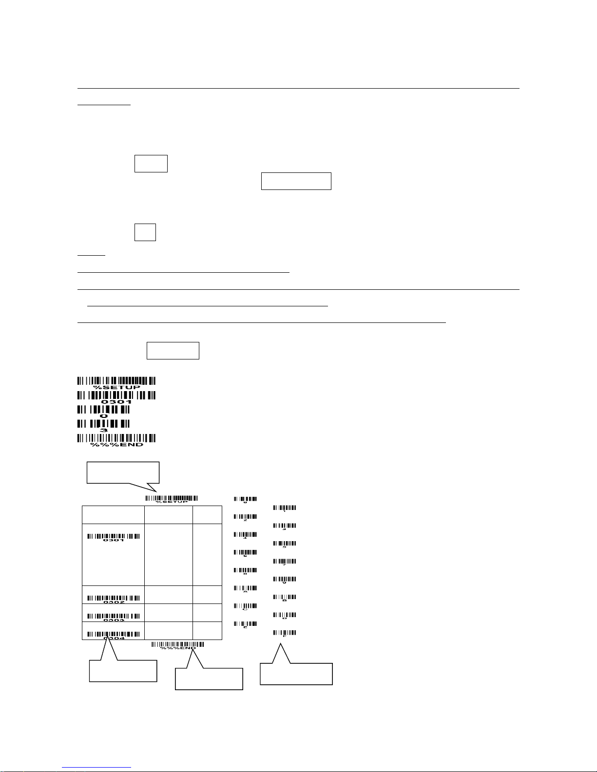
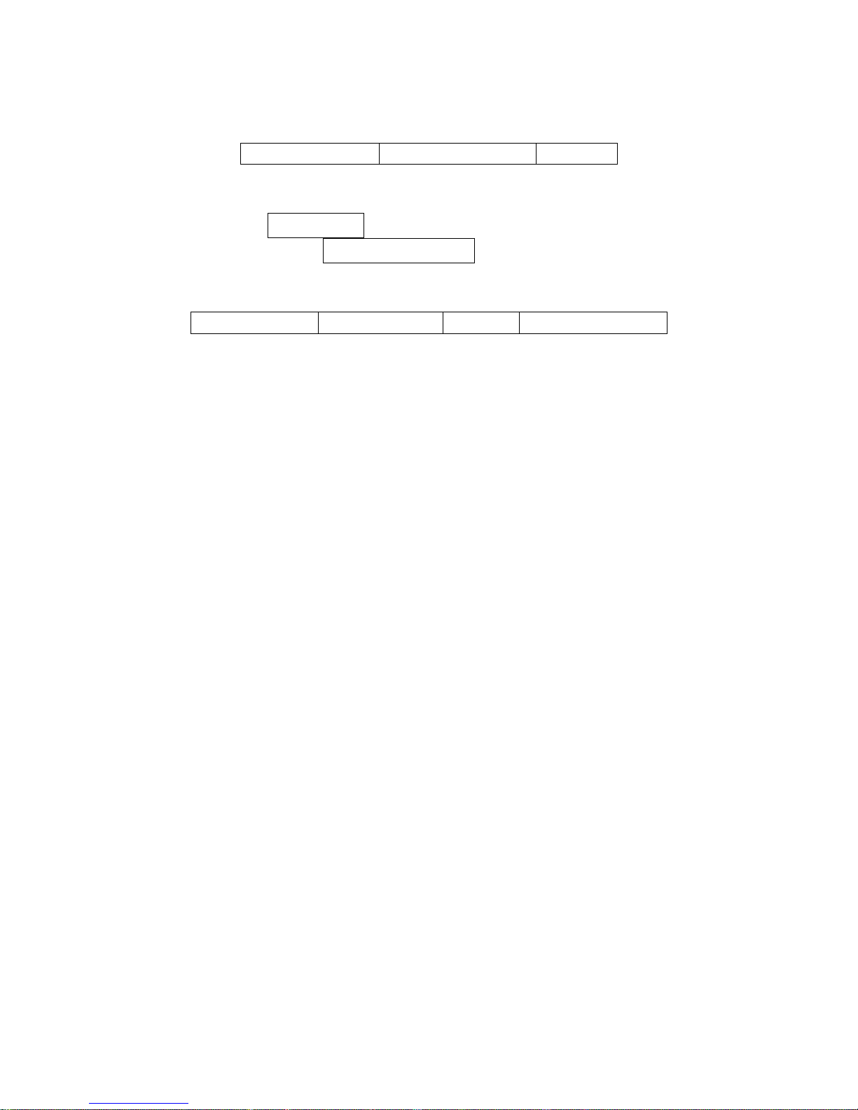
Refer to the next page, the steps of programming are:
1. Scan the SETUP bar code on the parameter setting part.
2. Enter the option mode by scanning the Option bar code.
3. To the right of the option barcode, the necessary alphanumeric inputs are listed. Scan these
alphanumeric entries.
4. Scan the END bar code, listed on the lower right hand corner of each parameter setting part.
Notes:
1) Only one parameter can be setup at each time.
2) During the process of programming, LED is lighting to indicate the programming correctness. LED will
go off if any incorrect programming operation performed.
3) After each successful programming, LED will go off and the terminal will beep twice.
Example: to set Flow control to be XON/XOFF.
Steps: Scan the following barcodes in order.
SETUP
Option bar code
Option
Alpha.
entry
Flow control
None
RTS/CTS
(Host: Low RTS)
RTS/CTS
(Host: High RTS)
XON/XOFF
ACK/NAK
00*
01
02
03
04
Inter-character delay
00-99 (ms)
00-99
00*
Block trans. delay
00-99 (10 ms)
00-99
00*
Response delay
00-99 (100 ms)
00-99
00*
END
SETUP bar code
Alpha. entries
Option bar code
END bar code
Page 45

38
7-2 Some global settings
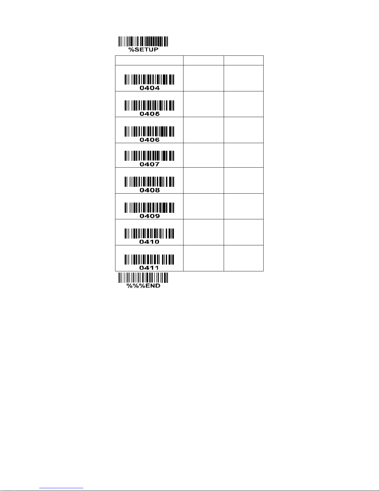
Multiple confirm: If this parameter is set to be lager than zero, the engine will require several successful
reads of same-decoded-data to confirm a valid reading. The number of successful reads can be different
according to different types of barcode. As the number of Multiple confirm gets larger, the engine’s
aggressiveness decreases. The number of successful reads required for different types of barcode is
listed below, which is related to the parameter of Multiple confirm.
Table 7-1 The number of successful reads (n)
Barcode type
Multiple confirm (m)
m=0
m=1
m=2
m>=3
EAN-13, EAN-8, UPC-A, Code93,
China Post, UK Plessey
n=2
n=3
n=4
n=m+1
UPC-E, Codebar, Interleaved 2/5,
Code39, Industry2/5, Matrix 2/5,
Code11, MSI Plessey, UPC-E1
n=3
n=4
n=4
n=m+1
UCCEAN128, Code128, GS1 DataBar,
GS1 DataBar Limited, GS1 DataBar
Expand, ISBT 128
n=1
n=2
n=3
n=m+1
Global Max./Min. code length: These two lengths are defined as the valid range of decoded barcode
data length. Make sure that the minimum length setting is no greater than the maximum length setting, or
otherwise the labels of the type of barcode will not be readable. In particular, the same value can be set
for both minimum and maximum reading length to force the fixed length barcode decoded.
Notes:
1. Please set the max./min. length for individual barcode in later sections, if a special demand is
requested.
2. The number of check digits is included in max./min. code length.
3. These two settings have no effect on the types of barcode with fixed-length, e.g. UPC-A, UPC-E,
EAN-13, EAN-8 and China Post.
Global G1-G4 string selection: The engine offer one or two string group for ALL types of barcode. By
setting one or two digits to indicate which string group you want to apply. You may refer to the chapters
of “String setting” and “String position & Number of truncated leading/ending character”.
Example: Group 1 → set 01 or 10. Group 2 and 4 → set 24 or 42.
All valid settings include 00, 01, 02, 03, 04, 10, 11, 12, 13, 14, 20, 21, 22, 23, 24, 30, 31, 32, 33, 34, 40,
41, 42, 43, and 44.
Element amendment: If it is enabled, the engine can read the barcode comprised with bars and spaces
in different scale.
Printable character only: If it is enabled, the engine will output the printable characters only, i.e. in ASCII
from 20H to 7EH.
Decoder optimization: If it is enabled, the engine will optimize the engine with error correction. This
function is not effective for all types of barcodes.
Page 46
39
SETUP
Option bar code
Option
Alpha. entry
Multiple confirm
00-09
(00: no )
00-09
00*
Global max. code length
04-99
04-99
99*
Global min. code length
01-99
01-99
04*
Global G1-G4 string selection
00-44
00-44
00*
Element amendment
Disable
Enable
00
01*
Printable character only
Disable
Enable
00*
01
Decoder optimization
Disable
Enable
00
01*
Reserved
END
Page 47

40
7-3 UPC-A
Read: Format
Leading zero
Data digits (11 digits)
Check digit
Check digit verification: The check digit is optional.
Check digit trans.: By setting Enable, check digit will be transmitted.
Code ID setting: Code ID is a one-or-two-character string used to represent the symbol upon a
succeeding reading. If you want application to transmit Code ID, you must set Code ID transmission to
be enabled. Refer to
7-28 String transmission
.
Insertion group selection: Refer to Global insertion group selection of the chapter of
7-2 Some global
settings
.
Supplement digits: The Supplement digits barcode is the supplemental 2 or 5 characters.
Format
Leading zero
Data digits (11 digits)
Check digit
Supplement digits 2 or 5
Truncation/Expansion:
Truncate leading zeros - The leading “0” digits of UPC-A data characters can be truncated when the
feature is enabled.
Example: Barcode “001234567895”,
Output: “1234567895”.
Expand to EAN-13 - It extends to 13-digits with a “0” leading digit when the feature is enabled.
Example: Barcode “001234567895”,
Output: “0001234567895”.
Truncate system character - The system character of UPC-A data can be truncated when the
feature is enabled.
Example: Barcode “001234567895”,
Output: “01234567895”.
Add country code - The country code (“0” for USA) can be added when the feature is enabled.
Example: Barcode “001234567895”,
Output: “0001234567895”.
Page 48
41
SETUP
Option bar code
Option
Alpha. entry
Read
Disable
Enable
00
01*
Check digit verification
Disable
Enable
00
01*
Check digit trans.
Disable
Enable
00
01*
Code ID setting
00-FF16
(ASCII)
00-FF16
<A>*
Insert group selection
00-66
00-66
00*
Supplement digits
None
2 digits
5 digits
2 or 5 digits
00*
01
02
03
Truncation/Expansion
None
Truncate leading zeros
Expand to EAN-13
Truncate system character
Add country code
00*
01
02
03
04
Reserved
END
Page 49

42
7-4 UPC-E
Read: Format
Leading zero
Data digits (6 digits)
Check digits
Check digit verification: The check digit is optional and made as the sum of the numerical value of the
data digits.
Check digit trans.: By setting Enable, check digit will be transmitted.
Code ID setting: Refer to Code ID setting of
7-3 UPC-A
.
Insertion group selection: Refer to Insertion group selection of
7-3 UPC-A
.
Supplement digits:
Format
Leading zero
Data digits (6 digits)
Check digit
Supplement digits 2 or 5
Truncation/Expansion:
Truncate leading zeros - The leading “0” digits of UPC-E data characters can be truncated when the
feature is enabled.
Example: Barcode “00123457”,
Output: “123457”.
Expand to EAN-13 - It extends to 13-digits with a “0” leading digit when the feature is enabled.
Example: Barcode “00123457”,
Output: “0001234000057”.
Expand to UPC-A - It extends to 12-digits when the feature is set to be enabled.
Example: Barcode “00123457”,
Output: “001234000057”.
Truncate system character - The system character “0” of UPC-E data can be truncated when the
feature is enabled.
Example: Barcode “00123457”,
Output: “0123457”.
Add country code - The country code (“0” for USA) can be added when the feature is enabled.
Example: Barcode “00123457”,
Output: “000123457”.
Page 50
43
SETUP
Option bar code
Option
Alpha. entry
Read
Disable
Enable
00
01*
Check digit verification
Disable
Enable
00
01*
Check digit trans.
Disable
Enable
00
01*
Code ID setting
00-FF16
(ASCII)
00-FF16
<D>*
Insert group selection
00-66
00-66
00*
Supplement digits
None
2 digits
5 digits
2 or 5 digits
00*
01
02
03
Truncation/Expansion
None
Truncate leading zeros
Expand to EAN-13
Expand to UPC-A
Truncate system character
Add country code
00*
01
02
03
04
05
Reserved
END
Page 51
44
7-5 UPC-E1
Read: Format
System character “1”
Data digits (6 digits)
Check digits
Check digit verification: The check digit verification is optional.
Check digit trans.: By setting Enable, check digit will be transmitted.
Code ID setting: Refer to Code ID setting of
7-3 UPC-A
.
Insertion group selection: Refer to Insertion group selection of
7-3 UPC-A
.
Supplement digits:
Format
System character “1”
Data digits (6 digits)
Check digit
Supplement digits 2 or 5
Truncation/Expansion:
Expand to EAN -13 - It extends to 13-digits with “0” digits when the feature is enabled.
Example: Barcode “10012341”,
Output: “0100120000031”.
Expand to UPC-A - It extends to 12-digits when the feature is set to be enabled.
Example: Barcode “10012341”,
Output: “100120000031”.
Truncate system character - The system character “1” of UPC-E1 data can be truncated when the
feature is enabled.
Example: Barcode “10012341”,
Output: “0012341”.
Add country code - The country code (“0” for USA) can be added when the feature is enabled.
Example: Barcode “10012341”,
Output: “010012341”.
Page 52
45
SETUP
Option bar code
Option
Alpha. entry
Read
Disable
Enable
00
01*
Check digit verification
Disable
Enable
00
01*
Check digit trans.
Disable
Enable
00
01*
Code ID setting
00-FF16
(ASCII)
00-FF16
<D>*
Insert group selection
00-66
00-66
00*
Supplement digits
None
2 digits
5 digits
2 or 5 digits
00*
01
02
03
Truncation/Expansion
None
Expand to EAN-13
Expand to UPC-A
Truncate system character
Add country code
00*
02
03
04
05
END
Page 53

46
7-6 EAN-13
Read:
Format
Data digits (12 digits)
Check digit
Check digit verification: The check digit is optional and made as the sum of the numerical value of the
data digits.
Check digit transmission: By setting Enable, check digit will be transmitted.
Code ID setting: Refer to Code ID setting of
7-3 UPC-A
.
Insertion group selection: Refer to Insertion group selection of
7-3 UPC-A
.
Supplement digits:
Format
Data digits (12 digits)
Check digit
Supplement digits 2 or 5
ISBN/ISSN conversion: The ISBN (International Standard Book Number) and ISSN (International
Standard Serial Number) are two kinds of barcode for books and magazines. The ISBN is 10 digits with
leading “978” and the ISSN is 8 digits with leading “977” of the EAN-13 symbology.
Example:
Barcode “9780194315104”, Output: “019431510X”.
Barcode “9771005180004”, Output: “10051805”.
ISBN/ISSN code ID setting: Refer to Code ID setting of
7-3 UPC-A
.
Page 54
47
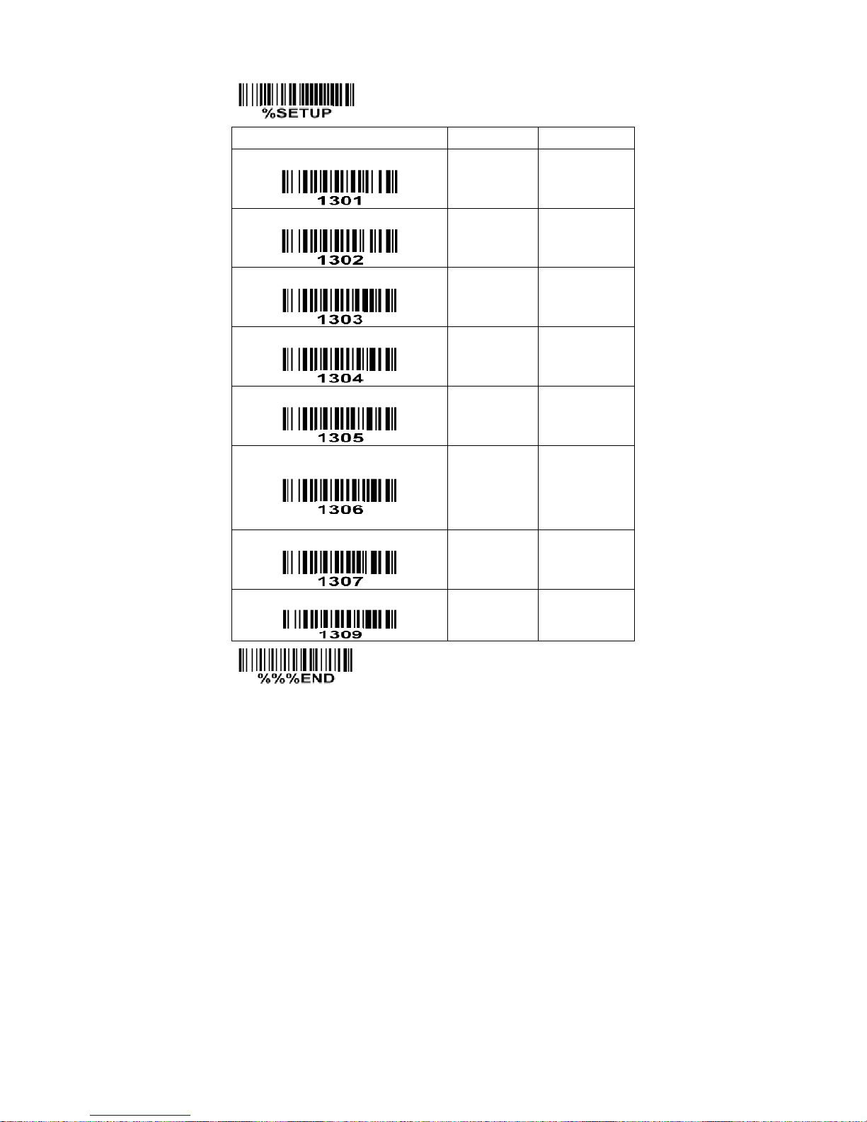
SETUP
Option bar code
Option
Alpha. entry
Read
Disable
Enable
00
01*
Check digit verification
Disable
Enable
00
01*
Check digit transmission
Disable
Enable
00
01*
Code ID setting
00-FF16
(ASCII)
00-FF16
<A>*
Insert group selection
00-66
00-66
00*
Supplement digits
None
2 digits
5 digits
2 or 5 digits
00*
01
02
03
ISBN/ISSN conversion
Disable
Enable
00*
01
ISBN/ISSN code ID setting
00-FF16
(ASCII)
00-FF16
<B>*
END
Page 55
48
7-7 EAN-8
Read:
Format
Data digits (7 digits)
Check digit
Check digit verification: The check digit is optional and made as the sum of the numerical value of the
data digits.
Check digit trans.: By setting Enable, check digit will be transmitted.
Code ID setting: Refer to Code ID setting of
7-3 UPC-A
.
Insertion group selection: Refer to Insertion group selection of
7-3 UPC-A
.
Supplement digits:
Format
Data digits (7 digits)
Check digit
Supplement Digits 2 or 5
Truncation/Expansion: Refer to Truncation/Expansion of
7-3 UPC-A
.
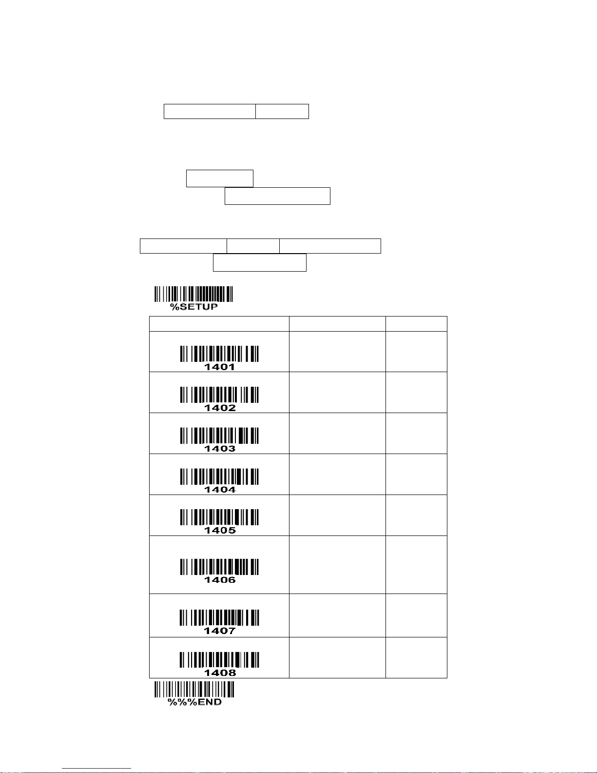
SETUP
Option bar code
Option
Alpha. entry
Read
Disable
Enable
00
01*
Check digit verification
Disable
Enable
00
01*
Check digit trans.
Disable
Enable
00
01*
Code ID setting
00-FF16
(ASCII)
00-FF16
<A>*
Insert group selection
00-66
00-66
00*
Supplement digits
None
2 digits
5 digits
2 or 5 digits
00*
01
02
03
Truncation/Expansion
None
Truncate leading zero
Expand to EAN-13
00*
01
02
Reserved
END
Page 56

49
7-8 Code 39
Read:
Format
*
Data digits (variable)
Check digit (optional)
*
Check digit verification: The check digit is optional and made as the sum module 43 of the numerical
value of the data digits.
Check digit transmission: By setting Enable, check digit will be transmitted.
Max./Min. code length: Each symbology has own max./min. code length. If both setting of max./min.
code length are “00”s, the setting of global max./min. code length is effective. The length is defined as to
the actual barcode data length to be sent. Label with length exceeds these limits will be rejected. Make
sure that the minimum length setting is no greater than the maximum length setting, or otherwise all the
labels of the symbology will not be readable. In particular, you can see the same value for both minimum
and maximum reading length to force the fixed length barcode decoded.
Code ID setting: Refer to Code ID setting of
7-3 UPC-A
.
Insertion group selection: Refer to Insertion group selection of
7-3 UPC-A
.
Start/End transmission: The start and end characters of Code 39 are “*”s. You can transmit all data
digits including two “*”s.
“*” as data character: By setting Enable, “*” can be recognized as data character.
Convert Code 39 to Code 32: Code 32 is a variant of Code 39 used by the Italian pharmaceutical
industry. Note that Code 39 must be enabled in order for this parameter to function.
Format of Code 32
“A” (optional)
Data digits (8 digits)
Check digit
Code 32 Prefix “A” transmission: By setting Enable, the prefix character “A” can be added to all Code 32
barcodes.
Trioptic Code 39 read: Trioptic Code 39 is a variant of Code 39 used in the marking of magnetic tapes
and computer cartridges. Trioptic Code 39 symbols always contain six characters.
Format
$
Data digits (6 digits)
$
Trioptic Code 39 Start/End transmission: The start and end characters of Trioptic Code 39 are “$”s. You
can transmit all data digits including two “$”s.
Page 57
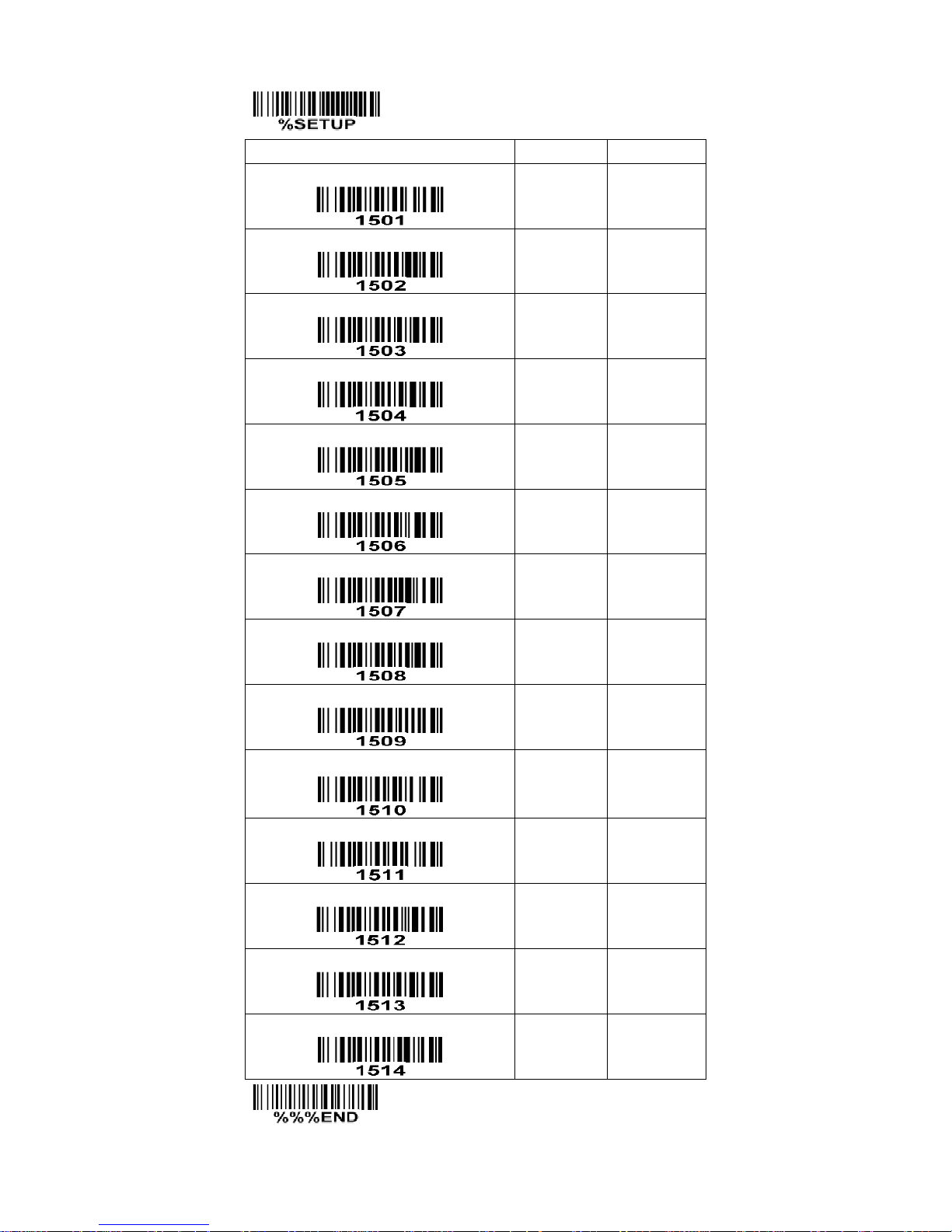
50
SETUP
Option bar code
Option
Alpha. entry
Read
Disable
Enable
00
01*
Check digit verification
Disable
Enable
00*
01
Check digit transmission
Disable
Enable
00*
01
Max. code length
00-99
00-99
00*
Min. code length
00-99
00-99
01*
Code ID setting
00-FF16
(ASCII)
00-FF16
<M>*
Insert group selection
00-66
00-66
00*
Format
Standard
Full ASCII
00*
01
Start/End transmission
Disable
Enable
00*
01
“*” as data character
Disable
Enable
00*
01
Convert Code 39 to Code 32
Disable
Enable
00*
01
Code 32 Prefix “A” transmission
Disable
Enable
00*
01
Trioptic Code 39 read
Disable
Enable
00*
01
Trioptic Code 39 Start/End transmission
Disable
Enable
00*
01
END
Page 58
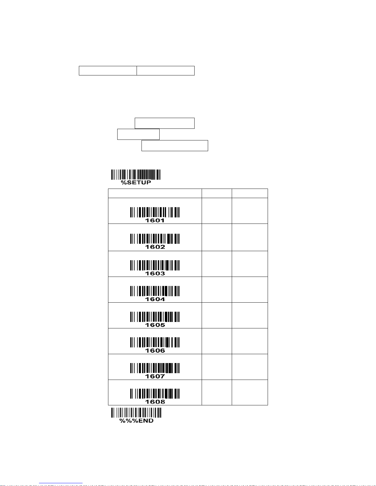
51
7-9 Interleaved 2 of 5
Read:
Format
Data digits (Variable)
Check digit (optional)
Check digit verification: The check digit is made as the sum module 10 of the numerical values of all data
digits. There are two optional check digit algorithms: the specified Uniform Symbology Specification
(USS) and the Optical Product Code Council (OPCC).
Check digit transmission: By setting Enable, check digit will be transmitted.
Max./Min. code length: Refer to Max./Min. code length of
7-8 Code 39
.
Code ID setting: Refer to Code ID setting of
7-3 UPC-A
.
Insertion group selection: Refer to Insertion group selection of
7-3 UPC-A
.
SETUP
Option bar code
Option
Alpha. entry
Read
Disable
Enable
00
01*
Check digit verification
Disable
USS
OPCC
00*
01
02
Check digit transmission
Disable
Enable
00*
01
Max. code length
00-99
00-99
00*
Min. code length
00-99
00-99
06*
Code ID setting
00-FF16
(ASCII)
00-FF16
<I>*
Insert group selection
00-66
00-66
00*
Reserved
END
Page 59
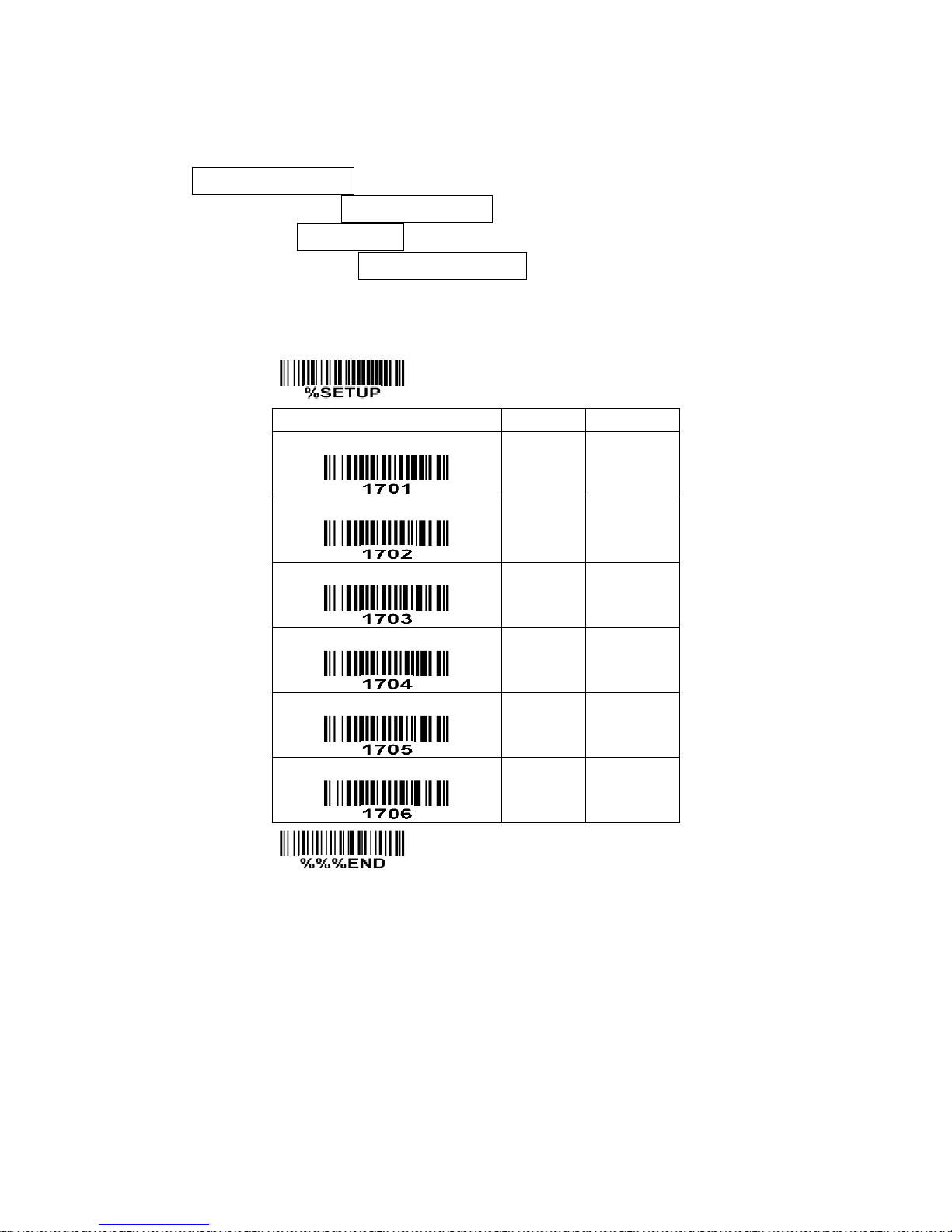
52
7-10 Industrial 2 of 5
Read:
Format
Data digits (variable)
Max./Min. code length: Refer to Max./Min. code length of
7-8 Code 39
.
Code ID setting: Refer to Code ID setting of
7-3 UPC-A
.
Insertion group selection: Refer to Insertion group selection of
7-3 UPC-A
.
SETUP
Option bar code
Option
Alpha. entry
Read
Disable
Enable
00*
01
Max. code length
00-99
00-99
00*
Min. code length
00-99
00-99
00*
Code ID setting
00-FF16
(ASCII)
00-FF16
<H>*
Insert group selection
00-66
00-66
00*
Reserved
END
Page 60
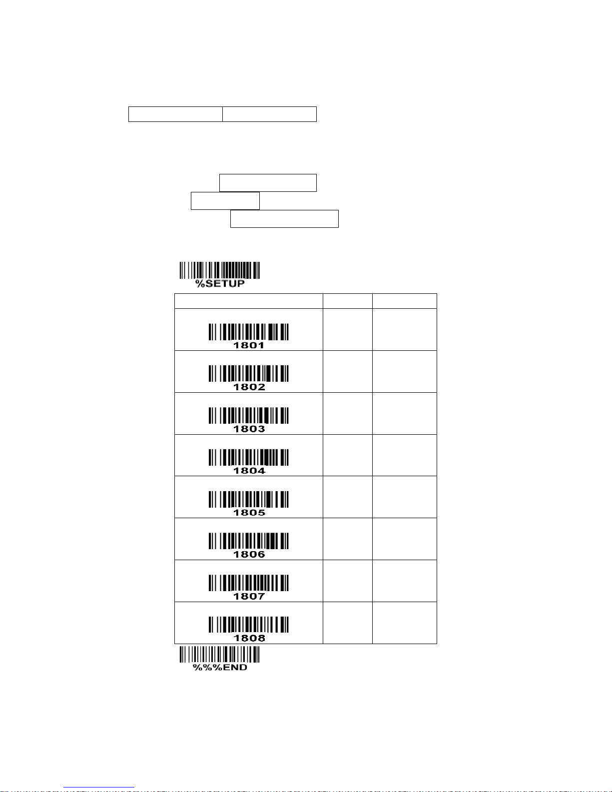
53
7-11 Matrix 2 of 5
Read:
Format
Data digits (variable)
Check digit (optional)
Check digit verification: The check digit is made as the sum module 10 of the numerical values of all data
digits.
Check digit transmission: By setting Enable, check digit will be transmitted.
Max./Min. code length: Refer to Max./Min. code length of
7-8 Code 39
.
Code ID setting: Refer to Code ID setting of
7-3 UPC-A
.
Insertion group selection: Refer to Insertion group selection of
7-3 UPC-A
.
SETUP
Option bar code
Option
Alpha. entry
Read
Disable
Enable
00
01*
Check digit verification
Disable
Enable
00*
01
Check digit transmission
Disable
Enable
00*
01
Max. code length
00-99
00-99
00*
Min. code length
00-99
00-99
06*
Code ID setting
00-FF16
(ASCII)
00-FF16
<X>*
Insert group selection
00-44
00-44
00*
Reserved
END
Page 61

54
7-12 Codabar
Read:
Format
Start
Data digits (variable)
Check digit (optional)
End
Check digit verification: The check digit is made as the sum module 16 of the numerical values of all data
digits.
Check digit transmission: By setting Enable, check digit will be transmitted.
Max./Min. code length: Refer to Max./Min. code length of
7-8 Code 39
.
Code ID setting: Refer to Code ID setting of
7-3 UPC-A
.
Insertion group selection: Refer to Insertion group selection of
7-3 UPC-A
.
Start/End type: Codabar has four pairs of Start/End pattern; you may select one pair to match your
application.
Start/End transmission: Refer to Start/End transmission of
7-8 Code 39
.
Start/End character equality: By setting Enable, the start and end character of a Codabar barcode must
be the same.
Page 62
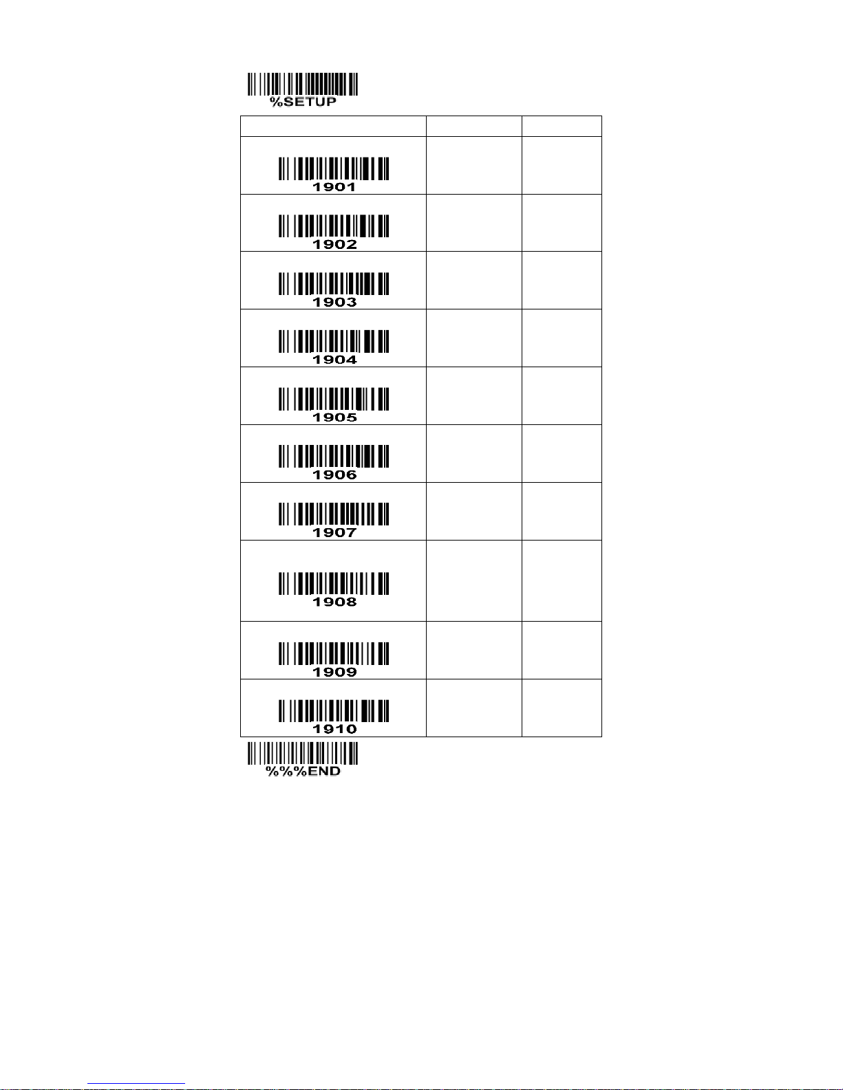
55
SETUP
Option bar code
Option
Alpha. entry
Read
Disable
Enable
00
01*
Check digit verification
Disable
Enable
00*
01
Check digit transmission
Disable
Enable
00*
01
Max. code length
00-99
00-99
00*
Min. code length
00-99
00-99
00*
Code ID setting
00-FF16
(ASCII)
00-FF16
<N>*
Insert group selection
00-66
00-66
00*
Start/End type
ABCD/ABCD
abcd/abcd
ABCD/TN*E
abcd/tn*e
00*
01
02
03
Start/End transmission
Disable
Enable
00*
01
Start/End character equality
Disable
Enable
00*
01
END
Page 63
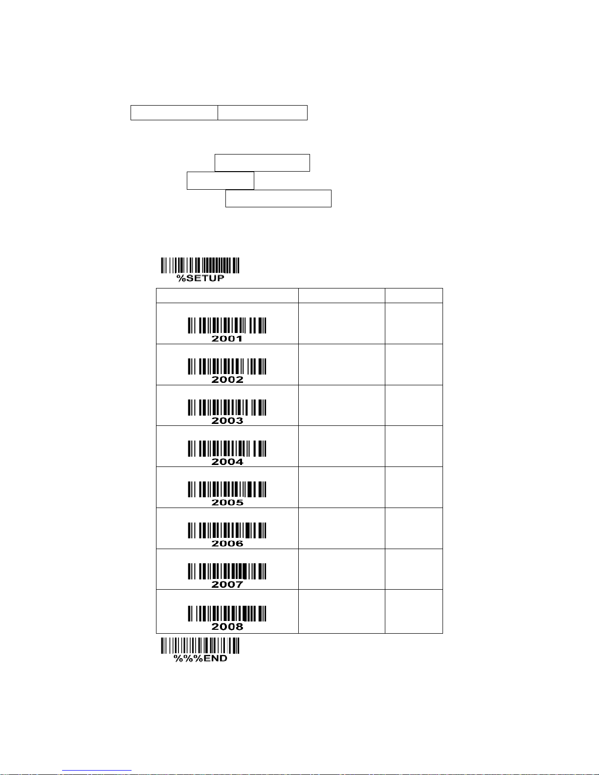
56
7-13 Code 128
Read:
Format
Data digits (variable)
Check digit (optional)
Check digit verification: The check digit is made as the sum module 103 of all data digits.
Check digit transmission: By setting Enable, check digit will be transmitted.
Max./Min. code length: Refer to Max./Min. code length of
7-8 Code 39
.
Code ID setting: Refer to Code ID setting of
7-3 UPC-A
.
Insertion group selection: Refer to Insertion group selection of
7-3 UPC-A
.
Truncate leading zeros: The leading “0” digits of Code 128 barcode characters can be truncated when
the feature is enabled.
SETUP
Option bar code
Option
Alpha. entry
Read
Disable
Enable
00
01*
Check digit verification
Disable
Enable
00
01*
Check digit transmission
Disable
Reserved
00*
01
Max. code length
00-99
00-99
00*
Min. code length
00-99
00-99
01*
Code ID setting
00-FF16
(ASCII)
00-FF16
<K>*
Insert group selection
00-66
00-66
00*
Truncate leading zeros
Disable
All leading “0”s
Only the first “0”
00*
01
02
END
Page 64
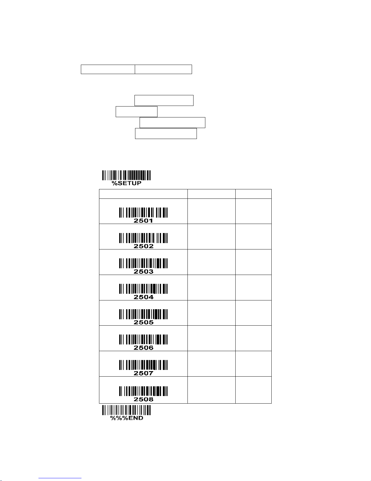
57
7-14 UCC/EAN 128
Read:
Format
Data digits (variable)
Check digit (optional)
Check digit verification: The check digit is made as the sum module 103 of all data digits.
Check digit transmission: By setting Enable, check digit will be transmitted.
Max. /Min. code length: Refer to Max./Min. code length of
7-8 Code 39
.
Code ID setting: Refer to Code ID setting of
7-3 UPC-A
.
Insertion group selection: Refer to Insertion group selection of
7-3 UPC-A
.
Truncate leading zeros: Refer to Truncate leading zeros of
7-12 Code 128
.
SETUP
Option bar code
Option
Alpha. entry
Read
Disable
Enable
00
01*
Check digit verification
Disable
Enable
00
01*
Check digit transmission
Disable
Reserved
00*
01
Max. code length
00-99
00-99
00*
Min. code length
00-99
00-99
01*
Code ID setting
00-FF16
(ASCII)
00-FF16
<K>*
Insert group selection
00-66
00-66
00*
Truncate leading zeros
Disable
All leading “0”s
Only the first “0”
00*
01
02
END
Page 65

58
7-15 ISBT 128
Read:
Format
“=” or “&”
Data digits (variable)
Check digit (optional)
Check digit verification: The check digit verification is optional.
Check digit transmission: By setting Enable, check digit will be transmitted.
Max./Min. code length: Refer to Max./Min. code length of
7-8 Code 39
.
Code ID setting: Refer to Code ID setting of
7-3 UPC-A
.
Insertion group selection: Refer to Insertion group selection of
7-3 UPC-A
”.
Page 66
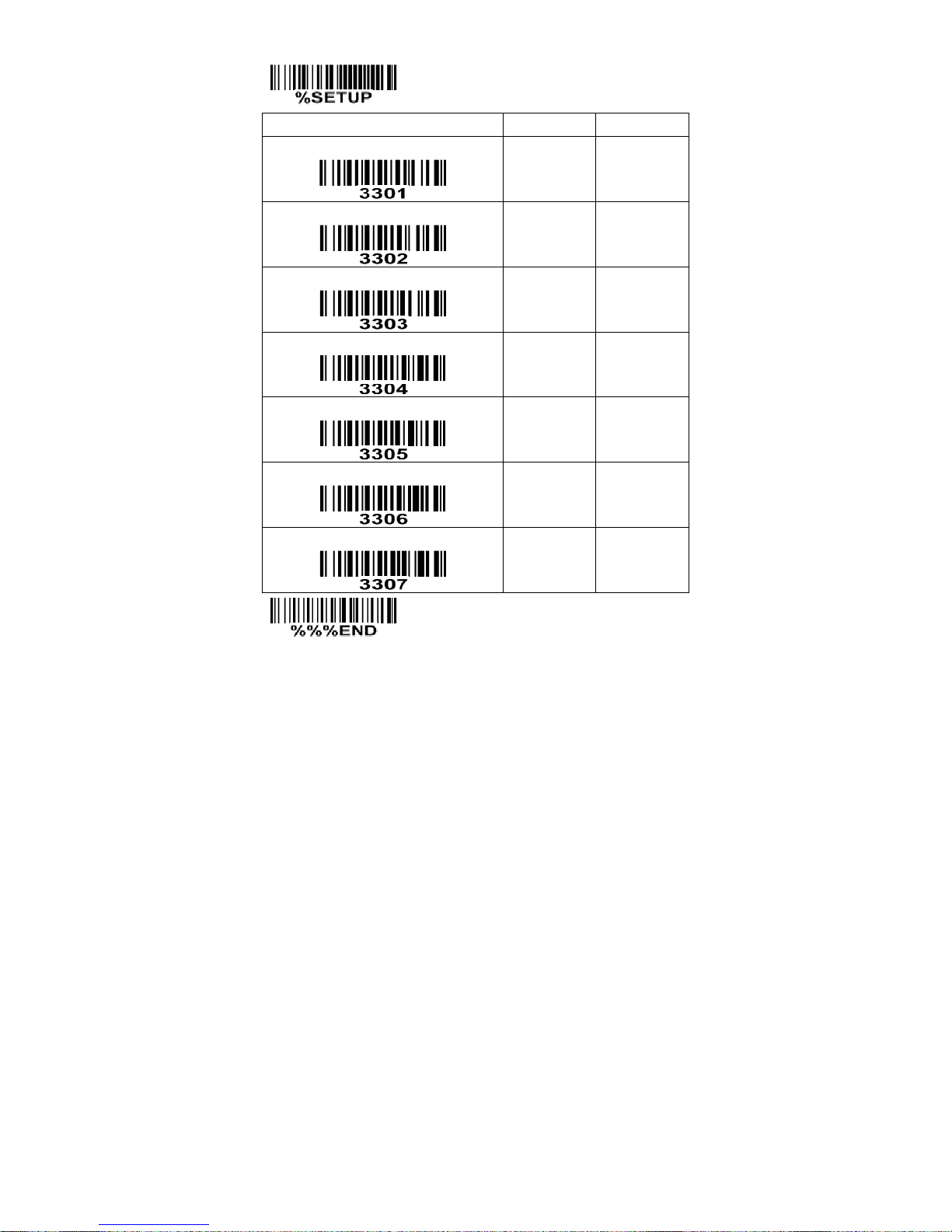
59
SETUP
Option bar code
Option
Alpha. entry
Read
Disable
Enable
00
01*
Check digit verification
Disable
Enable
00
01*
Check digit transmission
Disable
Reserved
00*
01
Max. code length
00-99
00-99
00*
Min. code length
00-99
00-99
01*
Code ID setting
00- FF16
(ASCII)
00-FF16
<K>*
Insert group selection
00-66
00-66
00*
END
Page 67
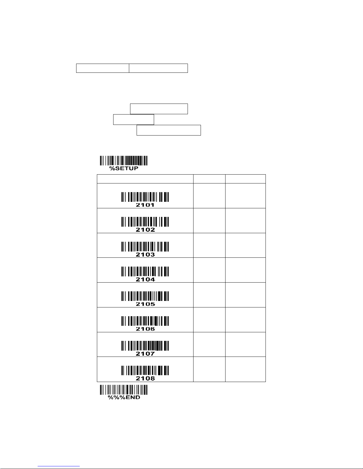
60
7-16 Code 93
Read:
Format
Data digits (variable)
2 check digits (optional)
Check digit verification: The check digit is made as the sum module 47 of the numerical values of all data
digits.
Check digit transmission: By setting Enable, check digit will be transmitted.
Max./Min. code length: Refer to Max./Min. code length of
7-8 Code 39
.
Code ID setting: Refer to Code ID setting of
7-3 UPC-A
.
Insertion group selection: Refer to Insertion group selection of
7-3 UPC-A
.
SETUP
Option bar code
Option
Alpha. entry
Read
Disable
Enable
00
01*
Check digit verification
Disable
Enable
00
01*
Check digit transmission
Disable
Enable
00*
01
Max. code length
00-99
00-99
00*
Min. code length
00-99
00-99
01*
Code ID setting
00-FF16
(ASCII)
00-FF16
<L>*
Insert group selection
00-66
00-66
00*
Reserved
END
Page 68
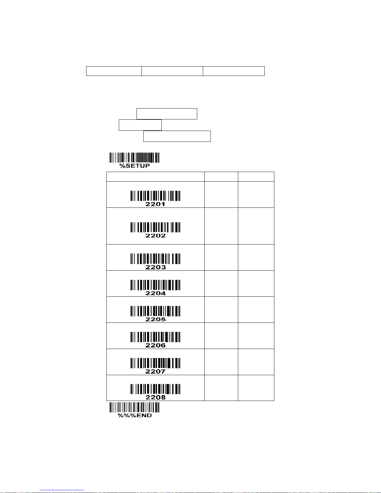
61
7-17 Code 11
Read:
Format
Data digits (variable)
Check digit 1 (optional )
Check digit 2 (optional)
Check digit verification: The check digit is presented as the sum module 11 of all data digits.
Check digit transmission: By setting Enable, check digit 1 and check digit 2 will be transmitted upon your
selected check digit verification method.
Max./Min. code length: Refer to Max./Min. code length of
7-8 Code 39
.
Code ID setting: Refer to Code ID setting of
7-3 UPC-A
.
Insertion group selection: Refer to Insertion group selection of
7-3 UPC-A
.
SETUP
Option bar code
Option
Alpha. entry
Read
Disable
Enable
00*
01
Check digit verification
Disable
One digit
Reserved
Reserved
00
01*
02
03
Check digit transmission
Disable
Enable
00*
01
Max. code length
00-99
00-99
00*
Min. code length
00-99
00-99
00*
Code ID setting
00-FF16
(ASCII)
00-FF16
<V>*
Insert group selection
00-66
00-66
00*
Reserved
END
Page 69
62
7-18 MSI/Plessey
Read:
Format
Data digits (variable)
Check digit 1 (optional)
Check digit 2 (optional)
Check digit verification: The MSI/Plessey has one or two optional check digits. There are three methods
of verifying check digits, i.e. Mod10, Mod10/10 and Mod 11/10. The check digit 1 and check digit 2 will
be calculated as the sum module 10 or 11 of the data digits.
Check digit transmission: By setting Enable, check digit 1 and check digit 2 will be transmitted upon your
selected check digit verification method.
Max./Min. code length: Refer to Max./Min. code length of
7-8 Code 39
.
Code ID setting: Refer to Code ID setting of
7-3 UPC-A
.
Insertion group selection: Refer to Insertion group selection of
7-3 UPC-A
.
SETUP
Option bar code
Option
Alpha. entry
Read
Disable
Enable
00*
01
Check digit verification
Disable
1 digit (mod 10)
Reserved
Reserved
00*
01
02
03
Check digit transmission
Disable
Enable
00*
01
Max. code length
00-99
00-99
00*
Min. code length
00-99
00-99
00*
Code ID setting
00-FF16
(ASCII)
00-FF16
<O>*
Insert group selection
00-66
00-66
00*
Reserved
END
Page 70
63
7-19 UK/Plessey
Read:
Format
Data digits (variable)
2 check digits (optional)
Check digit verification: The UK/Plessey has one or two optional check digits. The check digit 1 and
check digit 2 will be calculated as the sum module 10 or 11 of the data digits.
Check digit transmission: By setting Enable, check digit will be transmitted.
Max./Min. code length: Refer to Max./Min. code length of
7-8 Code 39
.
Code ID setting: Refer to Code ID setting of
7-3 UPC-A
.
Insertion group selection: Refer to Insertion group selection of
7-3 UPC-A
.
SETUP
Option bar code
Option
Alpha. entry
Read
Disable
Enable
00*
01
Check digit verification
Disable
Enable
00
01*
Check digit transmission
Disable
Enable
00*
01
Max. code length
00-99
00-99
00*
Min. code length
00-99
00-99
01*
Code ID setting
00-FF16
(ASCII)
00-FF16
<U>*
Insert group selection
00-66
00-66
00*
Reserved
END
Page 71
64
7-20 China Post
Read:
Format
11 Data digits
Max. /Min. code length: Refer to Max./Min. code length of
7-8 Code 39
. The code length of China Post is
11.
Code ID setting: Refer to Code ID setting of
7-3 UPC-A
.
Insertion group selection: Refer to Insertion group selection of
7-3 UPC-A
.
SETUP
Option bar code
Option
Alpha. entry
Read
Disable
Enable
00
01*
Reserved
Reserved
Max. code length
00-99
00-99
11*
Min. code length
00-99
00-99
11*
Code ID setting
00-FF16
(ASCII)
00-FF16
<T>*
Insert group selection
00-66
00-66
00*
Reserved
END
Page 72

65
7-21 China Finance
Note: This type of barcode is not Omni-directionally decodable. The encodable character set includes
numeric 0 to 9. Among the symbol of 0 to 9, 0 and 2, 4 and 9, 5 and 8, 6 and 7, have the symmetrical
pattern; the pattern of 1 and 3 is symmetrical.
Read:
Format
10 Data digits
Max./Min. code length: Refer to Max./Min. code length of
7-8 Code 39
.
Check digit verification: The check digit is made as the sum module 10 of the numerical values of all data
digits.
Leading character 5/6/7/8/9 converted to A/B/C/D/E: By setting, leading character 5/6/7/8/9 can be
converted to A/B/C/D/E.
Leading character assignment: By setting, only the barcode with the assigned leading character can be
output.
Code ID setting: Refer to Code ID setting of
7-3 UPC-A
.
Insertion group selection: Refer to Insertion group selection of
7-3 UPC-A
.
Page 73
66
SETUP
Option bar code
Option
Alpha. entry
Read
Disable
Enable
00
01*
Max. code length
00-99
00-99
10*
Min. code length
00-99
00-99
10*
Check digit verification
Disable
Reserved
00*
01
Leading character 5/6/7/8/9
converted to A/B/C/D/E
Disable
Enable
Only 5 converted to A
Only 6 converted to B
Only 7 converted to C
Only 8 converted to D
Only 9 converted to E
00
01*
02
03
04
05
06
Leading character assignment
Disable
Assigned to 0
Assigned to 5(A)
Assigned to 6(B)
Assigned to 7(C)
Assigned to 8(D)
Assigned to 9(E)
Assigned to 1
Assigned to 2
Assigned to 3
Assigned to 4
00
01*
02
03
04
05
06
07
08
09
10
Code ID setting
00-FF16
(ASCII)
00-FF16
<Y>*
Insert group selection
00-66
00-66
00*
END
Page 74

67
Laser Light Direction Setting: By scanning the barcode above, the
decoding direction of the terminal’s laser light is from left to right. By
scanning the up-side-down barcode above, the decoding direction of
the terminal’s laser light is from right to left.
Page 75

68
7-22 Telepen
Read:
Format
Start character (_)
Data digits (variable)
Check digit
End character (z)
Check digit verification: The check digit verification is optional.
Check digit transmission: By setting Enable, check digit will be transmitted.
Max./Min. code length: Refer to Max./Min. code length of
7-8 Code 39
.
Code ID setting: Refer to Code ID setting of
7-3 UPC-A
.
Insertion group selection: Refer to Insertion group selection of
7-3 UPC-A
.
Encode character set type: Two options. Same Telepen symbol, with different option, is associated
with different data output.
Alphanumeric- Supports both letters and numbers within the data source.
Numeric- Supports only numbers within the data source and ignores all letters.
Page 76
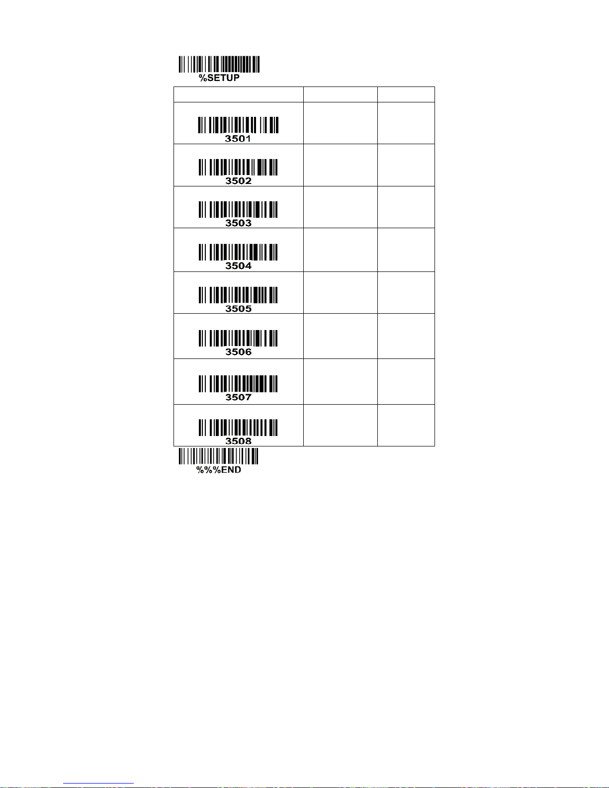
69
SETUP
Option bar code
Option
Alpha. entry
Read
Disable
Enable
00
01*
Check digit verification
Disable
Enable
00
01*
Check digit transmission
Disable
Enable
00*
01
Max. code length
00-99
00-99
00*
Min. code length
00-99
00-99
01*
Code ID setting
00-FF16
00-FF16
P*
Insertion group selection
00-66
00-66
00*
Encode character set type
Alphanumeric
Numeric
00*
01
END
Page 77
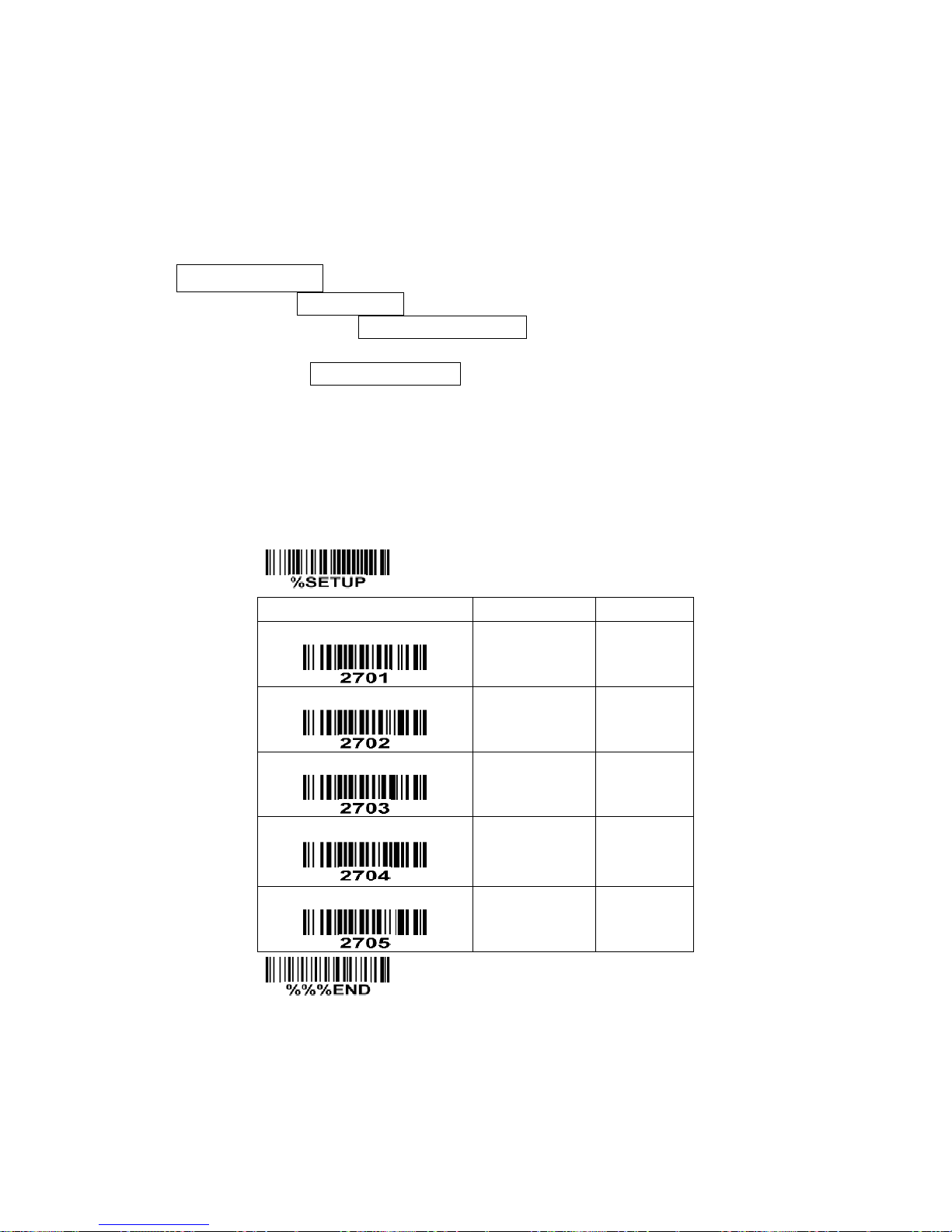
70
7-23 GS1 DataBar (GS1 DataBar Truncated)
GS1 DataBar Truncated is structured and encoded the same as the standard GS1 DataBar format,
except its height is reduced to a 13 modules minimum; while GS1 DataBar should have a height greater
than or equal to 33 modules.
Read:
Format
16 Data digits
Code ID setting: Refer to Code ID setting of
7-3 UPC-A
.
Insertion group selection: Refer to Insertion group selection of
7-3 UPC-A
.
Conversion:
UCC/EAN 128- Refer to Code ID transmission of
7-28 String transmission
, ]Cm will be identified as
AIM ID.
UPC-A or EAN-13- Barcode beginning with a single zero as the first digit has the leading “010”
stripped and the barcode reported as EAN-13. Barcode beginning with two or more zeros but not six
zeros has the leading “0100” stripped and the barcode reported as UPC-A.
SETUP
Option bar code
Option
Alpha. entry
Read
Disable
Enable
00
01*
Code ID setting
00-FF16
(ASCII)
00-FF16
<R >*
Insert group selection
00-66
00-66
00*
Conversion
None
UCC/EAN 128
UPC-A or EAN-13
00*
01
02
Reserved
END
Page 78
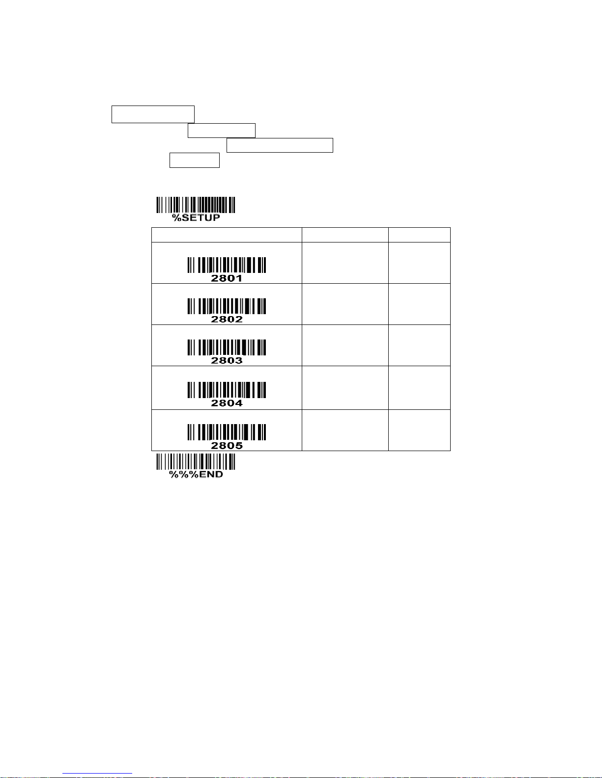
71
7-24 GS1 DataBar Limited
Read:
Format
16 Data digits
Code ID setting: Refer to Code ID setting of
7-3 UPC-A
.
Insertion group selection: Refer to Insertion group selection of
7-3 UPC-A
.
Conversion: Refer to Conversion of
7-23 GS1 DataBar (GS1 DataBar Truncated)
.
SETUP
Option bar code
Option
Alpha. entry
Read
Disable
Enable
00
01*
Code ID setting
00-FF16
(ASCII)
00-FF16
<R >*
Insert group selection
00-66
00-66
00*
Conversion
None
UCC/EAN 128
UPC-A or EAN-13
00*
01
02
Reserved
END
Page 79
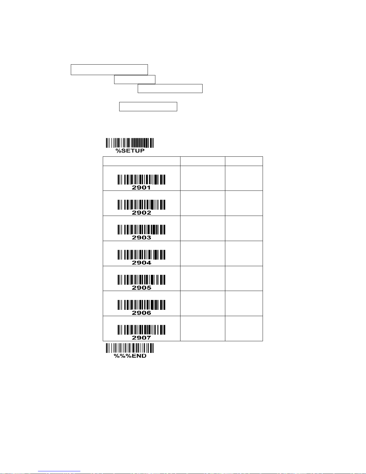
72
7-25 GS1 DataBar Expanded
Read:
Format
Data characters (variable)
Code ID setting: Refer to Code ID setting of
7-3 UPC-A
.
Insertion group selection: Refer to Insertion group selection of
7-3 UPC-A
.
Conversion:
UCC/EAN 128- Refer to Code ID transmission of
7-28 String transmission
, ]Cm will be identified as
AIM ID.
SETUP
Option bar code
Option
Alpha. entry
Read
Disable
Enable
00
01*
Max. code length
00-99
00-99
00*
Min. code length
00-99
00-99
01*
Code ID setting
00-FF16
(ASCII)
00-FF16
<R >*
Insert group selection
00-66
00-66
00*
Conversion
None
UCC/EAN 128
00*
01
Reserved
END
Page 80
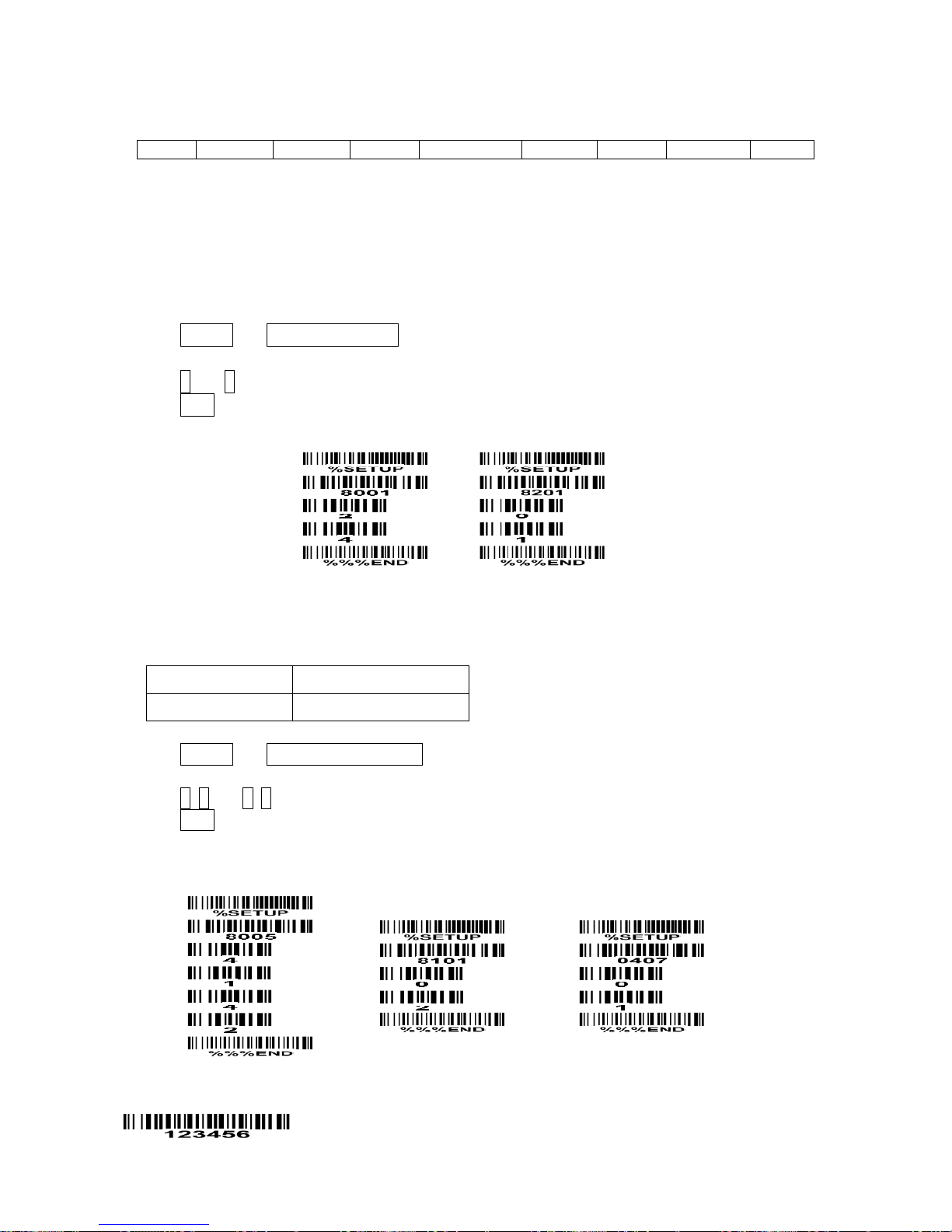
73
7-26 G1-G6 & FN1 substitution string setting
Format of barcode data transmission
Prefix
Code name
Preamble
Code ID
Code length
Code data
Code ID
Postamble
Suffix
Suffix string setting: The <enter > key is represented in different ASCII when it is applied by different OS.
For a Windows/DOS OS, <enter> is represented as <CR><LF> (0x0D 0x0A); for an APPLE MAC OS,
<enter> is represented as <CR> (0x0D); for a Linux/Unix OS, <enter> is represented as <LF> (0x0A).
Prefix / Suffix / Preamble / Postamble string setting:
They are appended to the data automatically when a barcode is decoded.
Example: Add a symbol of “$” as a prefix for all symbologies.
Steps:
1) Scan SETUP and Prefix string setting barcode.
2) Use the ASCII table to find the value of $→24.
3) Scan 2 and 4 from the barcode on the foldout back page.
4) Scan END barcode.
Scanning steps: Scan the following barcodes in order.
Insert G1/G2/G3/G4 string setting: The terminal offers 4 positions and 4 character strings to insert
among the symbol.
Example: Set G1 string to be “AB”.
Original code data
“1 2 3 4 5 6”
Output code data
“1 2 A B 3 4 5 6”
Steps:
1) Scan SETUP and Insert G1 string setting barcode “8005”.
2) Use the ASCII table to find the value of A→41, B→42.
3) Scan 4, 1 and 4, 2 from the barcode on the foldout back page.
4) Scan END barcode.
5) Refer to the chapter of
7-27 G1-G4 string position & Code ID position
.
6) Refer to the chapter of
7-2 Some global settings
.
Testing barcode:
Page 81
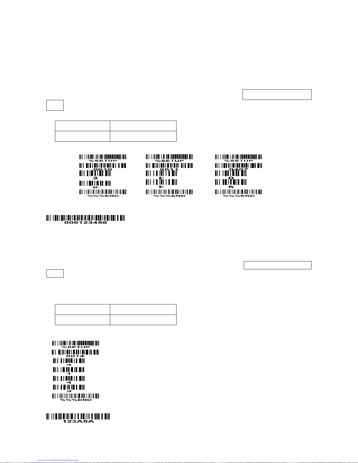
74
FN1 substitution string setting: The FN1 character (0x1D) in an UCC/EAN128 barcode, or a Code 128
barcode, or a GS1 DataBar barcode can be substituted with a defined string.
Truncate leading G5 string setting: By setting, a defined leading character or string can be truncated.
Also a single character can be un-defined.
Repeat of a G5 character setting: While G5 is set as a single defined/un-defined character, G5 can also
be set to be repeated. This setting is ignored when the truncate number is more than the barcode data
characters. The option of “FF” for this setting is not active while the option of Truncate leading G5 string
setting is “00”.
Example: Truncate all leading zeros for all symbologies.
Original code data
“0 0 0 1 2 3 4 5 6”
Output code data
“1 2 3 4 5 6”
Steps: scan the following data in order.
Testing barcode:
Truncate ending G6 string setting: By setting, a defined ending character or string can be truncated. Also
a single character can be un-defined.
Repeat of a G6 character setting: While G5 is set as a single defined/un-defined character, G6 can also
be set to be repeated. This setting is ignored when the truncate number is more than the barcode data
characters. The option of “FF” for this setting is not active while the option of Truncate ending G6 string
setting is “00”.
Single character C1/C2 replacement: By setting, a defined character in the data string can be replaced
by another defined character. The C1 and C2 replacement are applied simultaneously.
Example: Replace all the “A” character in a data string to be “B” character.
Original code data
“1 2 3 A 5 A”
Output code data
“1 2 3 B 5 B”
Steps: scan the following barcodes in order. The ASCII value for “A” is 41, and the ASCII value for “B” is
42.
Testing barcode:
Page 82
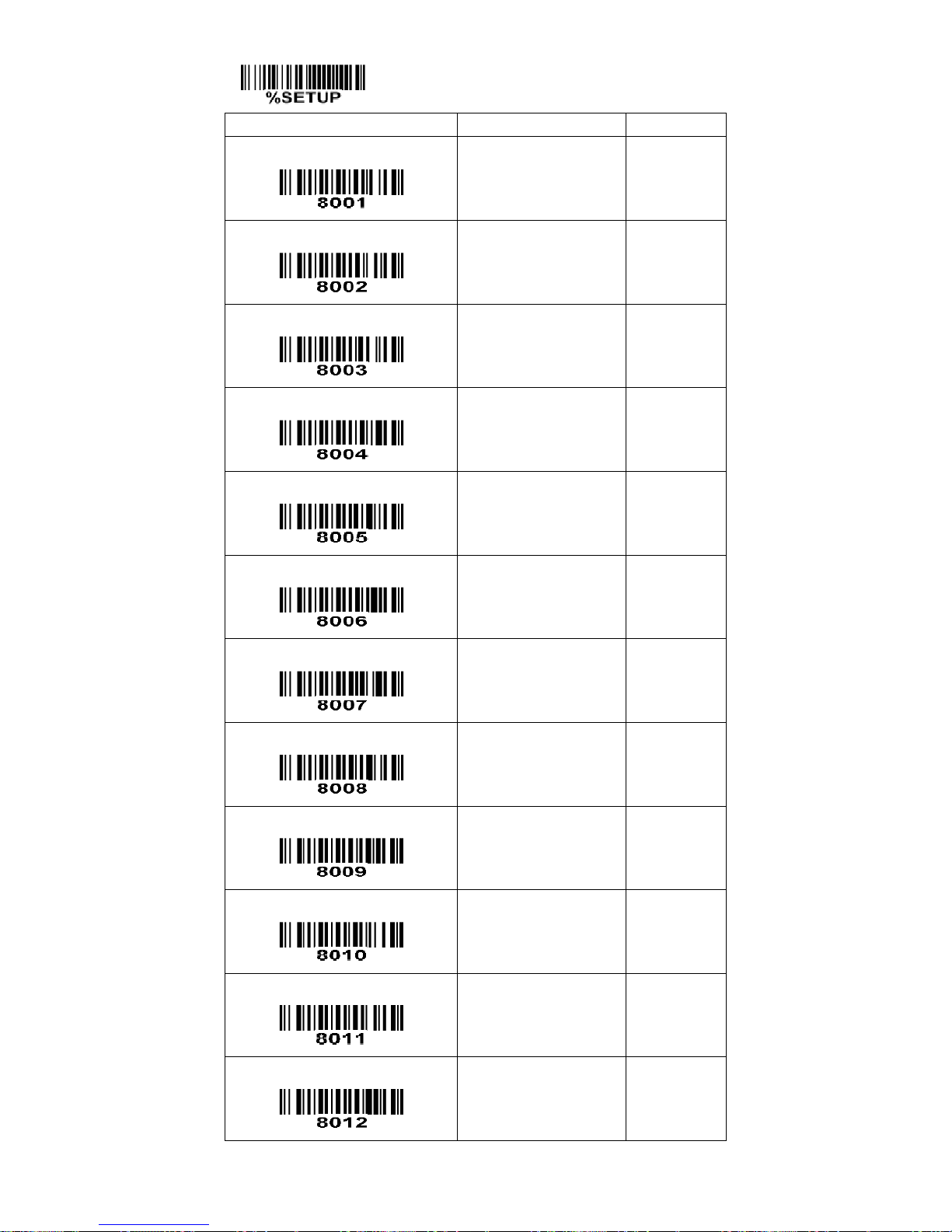
75
SETUP
Option bar code
Option
Alpha. entry
Prefix string setting
0-22 characters
None
00-FF16
00*
Suffix string setting
0-22 characters
<ENTER>
00-FF16
0D0A*
Preamble string setting
0-22 characters
None
00-FF16
00*
Postamble string setting
0-22 characters
None
00-FF16
00*
Insert G1 string setting
0-22 characters
None
00-FF16
00*
Insert G2 string setting
0-22 characters
None
00-FF16
00*
Insert G3 string setting
0-22 characters
None
00-FF16
00*
Insert G4 string setting
0-22 characters
None
00-FF16
00*
FN1 substitution string setting
0-4 characters
<SP>
00-FF16
20*
Truncate leading G5 string setting
A un-defined character
1-22 defined characters
<0>
00
01-7F16
30*
Repeat of a G5 character setting
Once
Defined times
Un-defined times (All)
01*
01-22
FF
Truncate ending G6 string setting
A un-defined character
1-22 defined characters
<0>
00
01-7F16
30*
Page 83
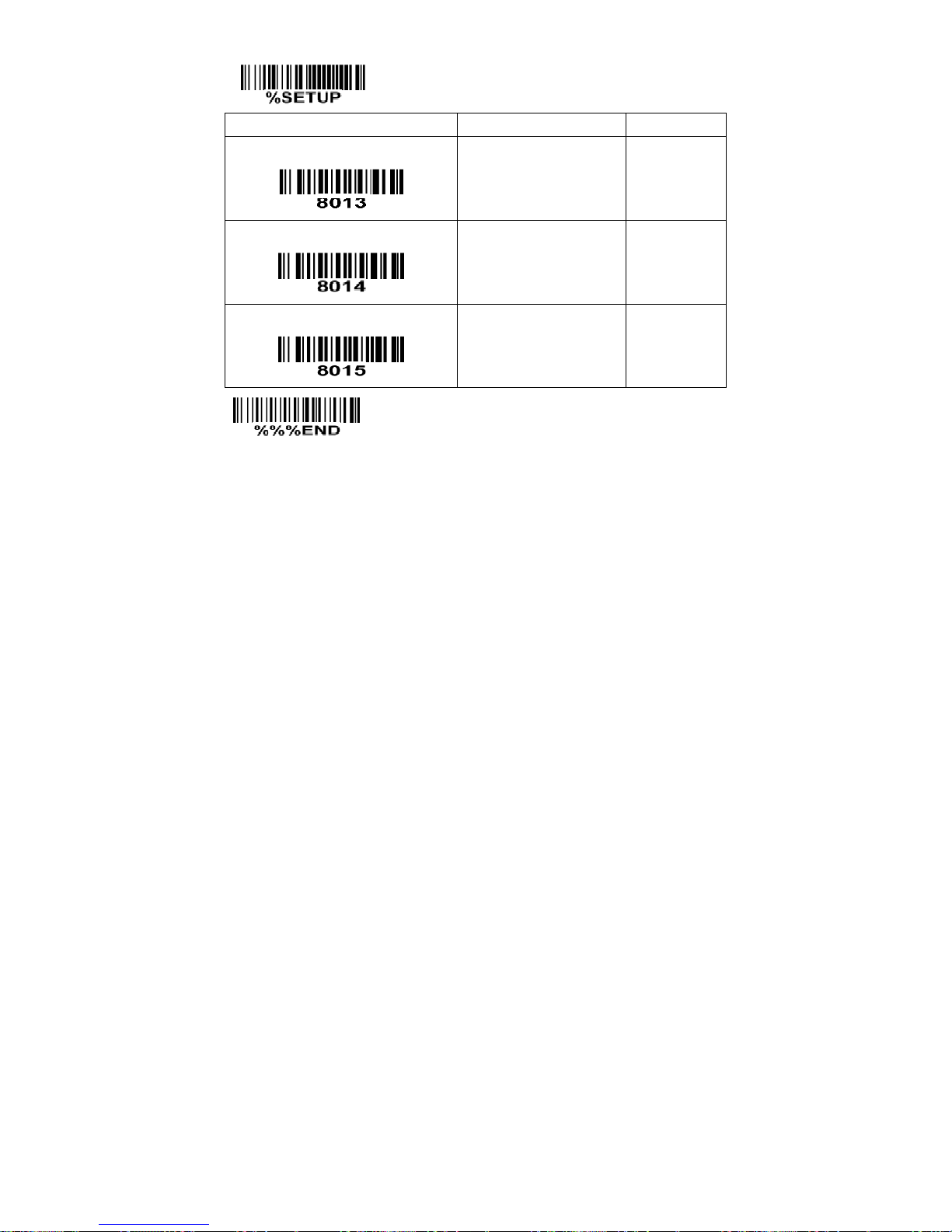
76
SETUP
Option bar code
Option
Alpha. entry
Repeat of a G6 character setting
Once
Defined times
Un-defined times (All)
01*
01-22
FF
Single character C1 replacement
<0000>
0000*
0000-FFFF
16
Single character C2 replacement
<0000>
0000*
0000-FFFF
16
END
Page 84
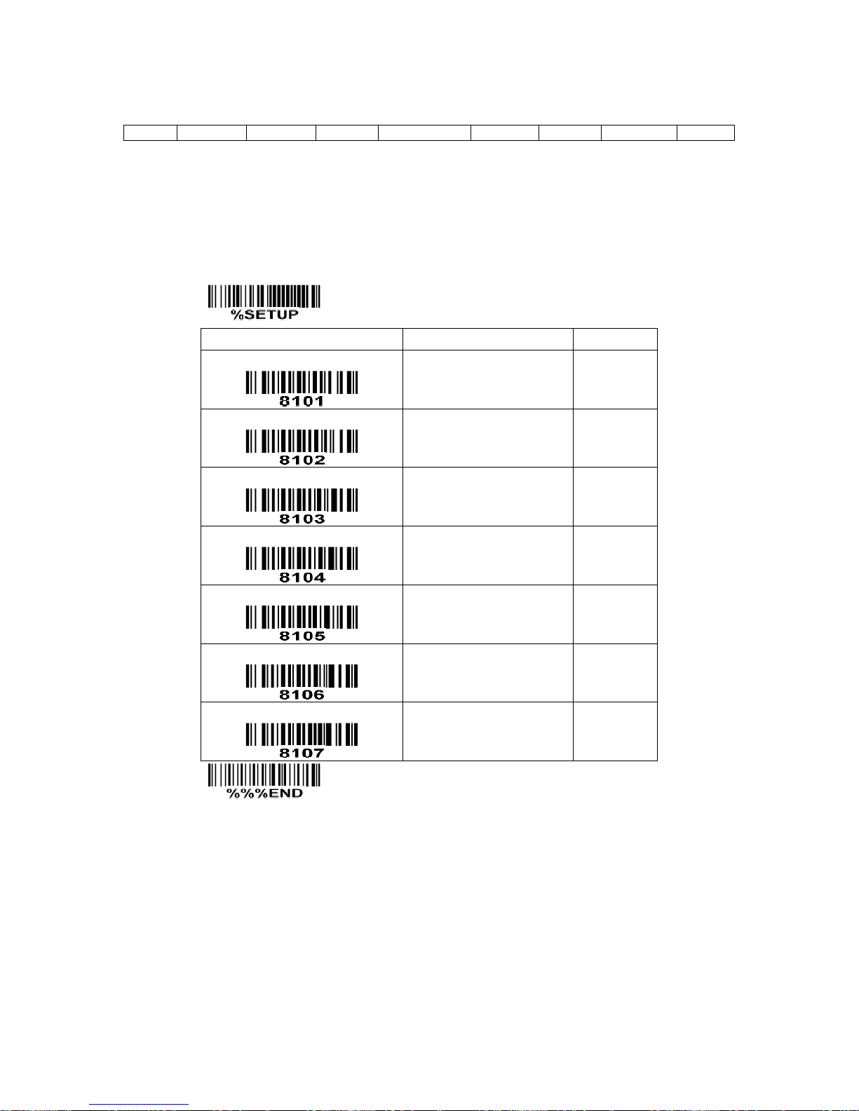
77
7-27 G1-G4 string position & Code ID position
Format of barcode data transmission
Prefix
Code name
Preamble
Code ID
Code length
Code data
Code ID
Postamble
Suffix
Insert G1/G2/G3/G4 string position: The terminal offers 4 positions to insert strings among the symbol. In
case of the insertion position is greater than the length of the symbol, the insertion of string is not
effective.
Code ID position: It is allowed to select different positions of code ID placement.
SETUP
Option bar code
Option
Alpha. entry
Insert G1 string position
00-99
00-99
00*
Insert G2 string position
00-99
00-99
00*
Insert G3 string position
00-99
00-99
00*
Insert G4 string position
00-99
00-99
00*
Code ID position
Before code data
After code data
00*
01
Reserved
Reserved
END
Page 85

78
7-28 String transmission
Note: The information in this chapter is closely related to the chapter of String setting.
Format of barcode data transmission
Prefix
Code name
Preamble
Code ID
Code length
Code data
Code ID
Postamble
Suffix
Prefix transmission: By setting Enable, prefix will be appended before the data transmitted.
Suffix transmission: By setting Enable, suffix will be appended after the data is transmitted.
Code name transmission: By setting Enable, code name will be transmitted before code data.
Preamble transmission: By setting Enable, preamble will be appended before the data transmitted.
Postamble transmission: By setting Enable, postamble will be appended after the data is transmitted.
Code ID transmission: Code ID can be transmitted in the format of either Proprietary ID or AIM ID. Refer
to
1-2 Default setting for each barcode
.
Code length transmission: The length of code data string can be transmitted before the code data when
Enable is selected. The length is represented by a number with two digits.
Case conversion: The characters within code data or the whole output string can be set in either upper
case or lower case.
FN1 substitution transmission: The terminal supports a FN1 substitution feature for keyboard wedge,
USB and RS-232 interface. The replacement string of FN1 can be chosen by user (see
7-26 G1-G6 &
FN1 substitution string setting
).
All-non-printable-character string transmission with string setting: By setting enable, all string settings,
e.g. Preamble transmission or Insert G1 string setting, are active for an all-non-printable-character string.
Here a non-printable character means a character with ASCII value between 0x00 to 0x1F.
Page 86
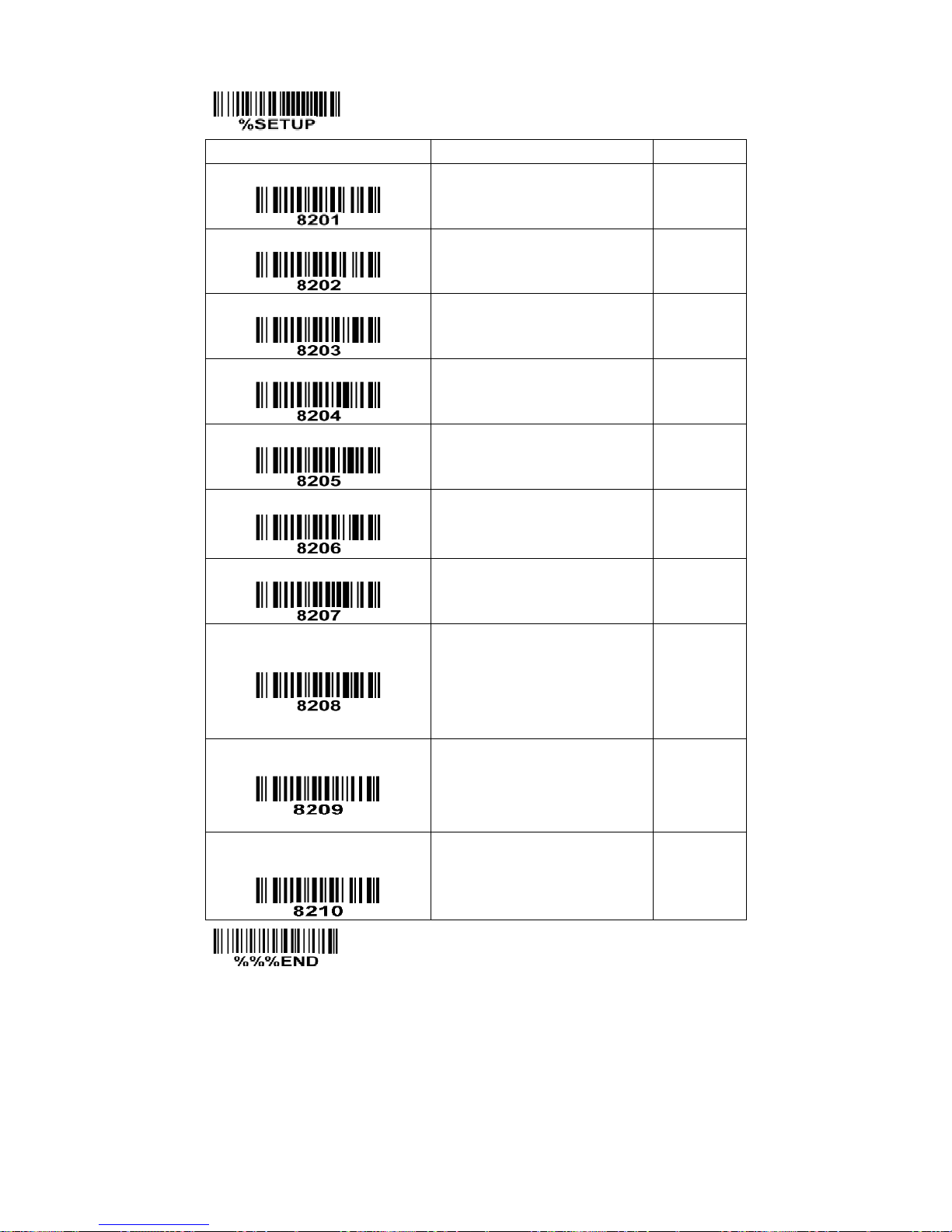
79
SETUP
Option bar code
Option
Alpha. entry
Prefix transmission
Disable
Enable
00*
01
Suffix transmission
Disable
Enable
00
01*
Code name transmission
Disable
Enable
00*
01
Preamble transmission
Disable
Enable
00*
01
Postamble transmission
Disable
Enable
00*
01
Code ID transmission
Disable
Proprietary ID
AIM ID
00*
01
02
Code length transmission
Disable
Enable
00*
01
Case conversion
Disable
Upper (data only)
Lower (data only)
Upper (whole string)
Lower (whole string)
00*
01
02
03
04
FN1 substitution transmission
Disable
Keyboard wedge/USB
RS-232
Keyboard wedge/USB/RS-232
00*
01
02
03
All-non-printable-character string
transmission with string setting
Disable
Enable
00*
01
END
Page 87

80
8 Barcode representing non-printable character
Notes to make the following barcode:
1. According to different barcode printing software, the method of printing following barcode is different.
2. If using CODESOFT software, firstly read the information through “Help→Index→Code128→Special input
syntax”. Also refer to ASCII table. For example, if we wish to make “F1” barcode, select “code128”, then
select “CODE A” type, and input “{DOC1}” as data.
Up ↑
Down ↓
Left ←
Right →
Page Up
Page Down
Backspace
Tab
Home
End
Enter
Insert
Delete
F1
F2
F3
F4
F5
F6
F7
F8
F9
F10
Esc
F11
F12
Page 88

81
9 ASCII Table
for keyboard wedge
for RS-232
H
L
0 1 0
1
0
Null
NUL
DLE 1 Up
F1
SOH
DC1
2
Down
F2
STX
DC2 3 Left
F3
ETX
DC3 4 Right
F4
EOT
DC4
5
PgUp
F5
ENQ
NAK
6
PgDn
F6
ACK
SYN 7
F7
BEL
ETB 8 Bs
F8
BS
CAN 9 Tab
F9
HT
EM A
F10
LF
SUB
B
Home
Esc
VT
ESC C End
F11
FF
FS D Enter
F12
CR
GS E Insert
Ctrl+
SO
RS
F
Delete
Alt+
SI
US
Notes: The 2nd and the 3rd columns above are used for keyboard wedge only.
H
L
2 3 4 5 6
7
0
SP 0 @ P ` p 1 ! 1 A Q a q 2 “ 2 B R b r 3 # 3 C S c s 4 $ 4 D T d
t
5 % 5 E U e u 6 & 6 F V f v 7 ‘ 7 G W g w 8 ( 8 H X h x 9 ) 9 I Y i y A * : J Z j
z
B + ; K [ k {
C , < L \ l | D - = M ] m } E . > N ^ n ~ F / ? O _ o
DEL
Example: ASCII “A” = “41”.
Page 89
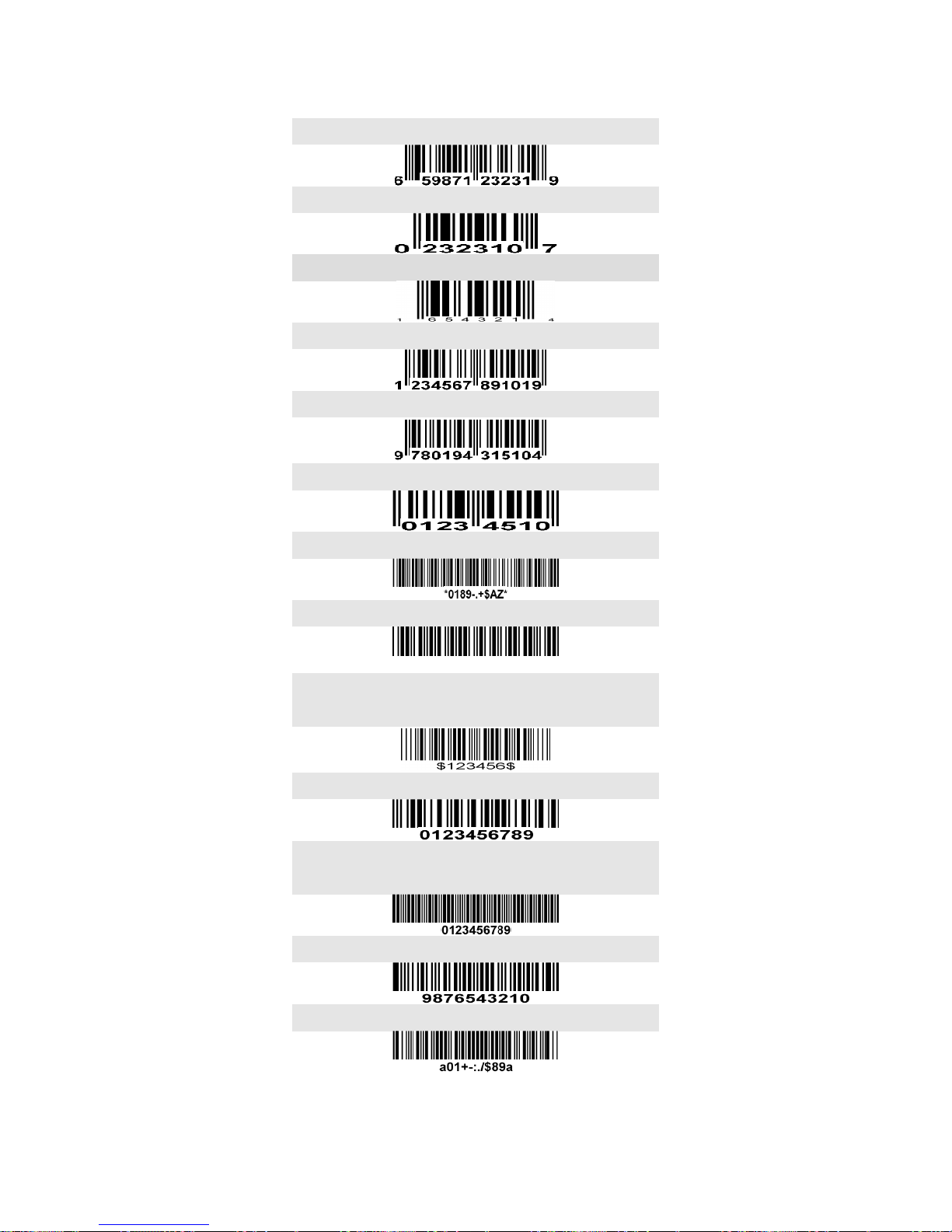
82
10 Test Chart
UPC-A
UPC-E
UPC-E1
EAN-13
ISBN/ISSN
EAN-8
Code 39
Code 32
A908765439
Trioptic Code 39
(Default setting: Disable)
Interleaved 2 of 5
Industrial 2 of 5
(Default setting: Disable)
Matrix 2 of 5
Codabar
Page 90
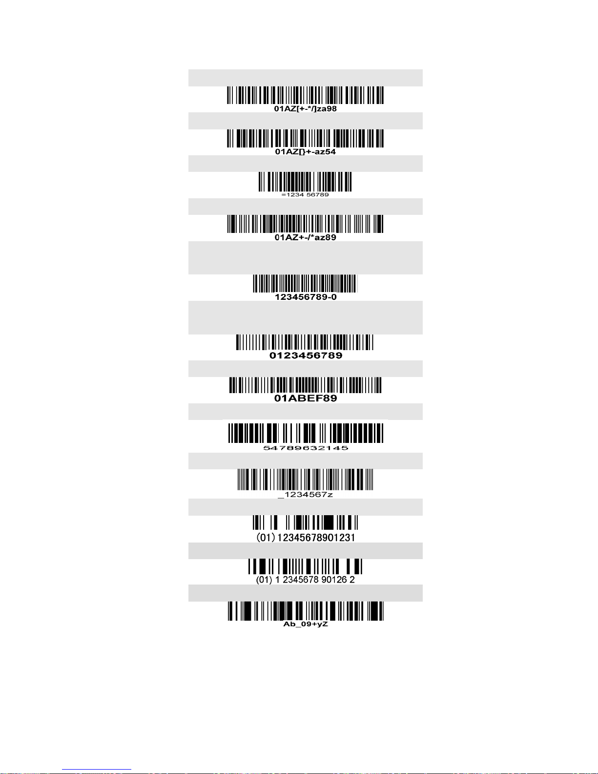
83
Test Chart (Continued)
Code 128
UCC/EAN 128
ISBT 128
Code 93
Code 11
(Default setting: Disable)
MSI/Plessey
(Default setting: Disable)
UK/Plessey
China Post
Telepen
GS1 DataBar (GS1 DataBar Truncated)
GS1 DataBar Limited
GS1 DataBar Expanded
Page 91

84
11 Configuration alphanumeric entry barcode
To finish parameter setting, please scan the bar code below.
Page 92
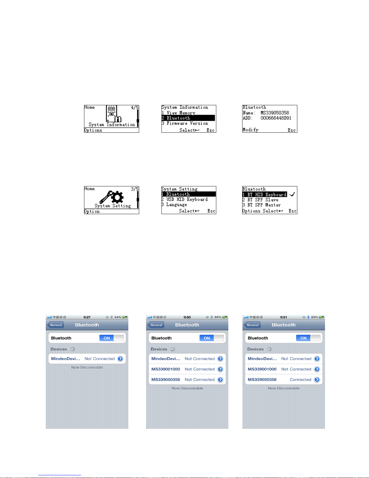
85
Appendix A: Connect iPhone to MS3390 via Bluetooth
Note: The version of iPhone should be higher than 3Gs in this document.
1. Check the name of MS3390 Bluetooth module
Check the name of MS3390 Bluetooth module by selecting System InformationBluetooth. In the
following example, the name is MS339050358.
2. Select the appropriate Bluetooth profile for MS3390
2.1. Make sure the Bluetooth module of MS3390 is powered on, i.e. the Blue LED on MS3390 is on.
2.2. Select the appropriate Bluetooth profile by setting System SettingBluetoothBT HID Keyboard.
3. Guide for iPhone to establish Bluetooth connection with MS3390
3.1. Make sure the Bluetooth module of the iPhone is powered on.
3.2. Enable the iPhone to search the nearby Bluetooth devices. After a while, the name list of Bluetooth
devices will be displayed on the screen.
3.3. Select the name of MS3390 Bluetooth module (e.g. “MS339050358” in this example) to establish a
Bluetooth connection.
3.4 Make sure the languages applied for iPhone and MS3390 are the same.
3.5 Open a note on iPhone and scan a barcode by MS3390 to test the Bluetooth connection.
Page 93
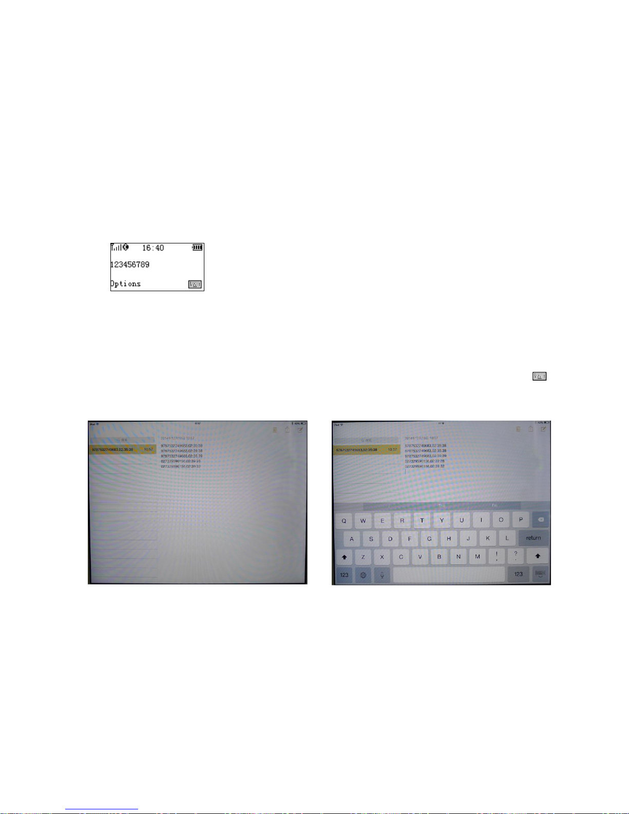
86
Appendix B: Pop up the Apple iOS on-screen keyboard
Note: Supports MS3390 with terminal firmware version V5.0.7 and above, and Bluetooth firmware
version V1.7 and above.
Usually, when you connect a Bluetooth barcode terminal to an Apple iOS device in HID mode, the iOS
device recognizes the terminal as a keyboard and hides the on-screen keyboard (or called built-in virtual
keyboard). Anytime you want to manually type anything using the iOS on-screen keyboard you need to
disconnect the terminal.
To eliminate such inconvenience, the MS3390 terminal provides the support of simultaneous use of
scanning and on-screen keystrokes. This feature is enabled by default and is operated as follows.
1. Connect MS3390 to the Apple iOS device via Bluetooth.
2. Enter the Scan menu on MS3390.
3. When press the right soft key of MS3390 once, the Apple iOS on-screen keyboard is popped-up.
Then user can manually type anything using the iOS on-screen keyboard and the terminal is
connected to iOS device by Bluetooth simultaneously. The right soft key is below the symbol
on MS3390 screen.
4. When press the right soft key of MS3390 once again, the Apple iOS on-screen keyboard is hidden.
On-screen keyboard hidden
On-screen keyboard popped-up
 Loading...