

ID Innovations Classic Line Series Magnetic Stripe Readers User Manual
Programmable
Magnetic Stripe Reader
for IBM AT, PS/2, USB and Compatible Keyboard Interfaces
ID Innovations Incorporated
Dual and Triple Track (Classic & Value Line Models)

ID Innovations Incorporated
ID Innovations Incorporated was founded in 1993 to provide low cost, high performance hardware and
software solutions for the identification market. This market is ever changing and continually growing,
requiring products that evolve and a manufacturer with an understanding of the market's needs. All of ID
Innovations' products show our commitment to engineering excellence and attention to detail. In order to
improve our products and services, we welcome any comments or suggestions that you may have. Our goal
is to become your source for providing solutions for your identification technology needs.
Mailing Address Shipping Address
ID Innovations Incorporated ID Innovations Incorporated
1244 Karla Drive Suite 104 1244 Karla Drive Suite 103
Hurst, TX 76053 Hurst, TX 76053
Tel (817) 285-8772
Fax (817) 285-8839
Copyright 1996 by ID Innovations Incorporated. All Rights Reserved.
Revision 7.71(1.07) 12/06
PRINTED IN THE UNITED STATES OF AMERICA
2

FCC Compliance
This equipment has been tested and found to comply with the limits for a Class A digital device (Classic Line) or Class
B digital device (Value Line), pursuant to part 15 of the FCC Rules. These limits are designed to provide reasonable
protection against harmful interference when the equipment is operated in a commercial environment. This equipment
generates, uses, and can radiate radio frequency energy and, if not installed and used in accordance with the
instruction manual, may cause harmful interference to radio communications. Operation of Class A digital equipment
(Classic Line) in a residential area is likely to cause harmful interference, in which case the user will be required to
correct the interference at his own expense.
Value Line Additional Compliance
In addition to FCC Class B compliance, the Value Line of Magnetic Stripe readers are Compliant with the following:
RoHS (Reduction of Hazardous Substance)
CE – (Certified for Europe)
California Proposition 65 Compliant
Copyright Information
The information contained in this manual is for informational purposes only and is subject to change without notice.
The contents of this manual are copyrighted. In addition, all software code in the ID Innovations Incorporated
Magnetic Card Reader itself is copyrighted. No part of this manual, or the ID Innovations Incorporated Magnetic Card
Reader software, may be copied or reproduced in any manner, or disseminated to any unauthorized person, without
the prior written permission of ID Innovations Incorporated.
LIMITATION OF LIABILITY
ID INNOVATIONS INCORPORATED LIABILITY FOR ANY DEFECTIVE PRODUCTS IS LIMITED TO THE REPAIR
OR REPLACEMENT OF THE PRODUCT AT OUR OPTION. ID INNOVATIONS INCORPORATED SHALL NOT BE
LIABLE FOR:
1. DAMAGE TO OTHER PROPERTY CAUSED BY ANY DEFECTS IN THIS PRODUCT, DAMAGES BASED UPON
INCONVENIENCE, LOSS OF USE OF THE PRODUCT, LOSS OF TIME, COMMERCIAL LOSS; OR
2. ANY OTHER DAMAGES, WHETHER INCIDENTAL, CONSEQUENTIAL OR OTHERWISE. SOME STATES DO
NOT ALLOW LIMITATIONS ON HOW LONG AN IMPLIED WARRANTY LASTS AND/OR DO NOT ALLOW THE
EXCLUSION OR LIMITATION OF INCIDENTAL OR CONSEQUENTIAL DAMAGES, SO THE ABOVE LIMITATIONS
AND EXCLUSIONS MAY NOT APPLY TO YOU.
3

Table of Contents
Features............................................................................................................................................................................ 6
Installation – MultiMode USB............................................................................................................................................ 6
Keyboard Wedge ....................................................................................................................................................... 6
Virtual COM Port ........................................................................................................................................................ 6
HID Mode ................................................................................................................................................................... 7
Installation - Keyboard Wedge (PS2 Style) ...................................................................................................................... 7
Installation – Serial (PS2 Style) ........................................................................................................................................ 7
Installation - Wand Emulation (PS2 Style)........................................................................................................................ 7
Installation – USB Adaptor................................................................................................................................................ 8
Mounting The Card Reader .............................................................................................................................................. 8
Operating The Card Reader ............................................................................................................................................. 8
Using the USB Programmer to Configure the Card Reader............................................................................................. 8
Using The Setup Mode To Configure The Card Reader .................................................................................................. 8
Interface (F1)............................................................................................................................................................ 12
Keyboard Country.............................................................................................................................................. 12
Transmit Speed, 0=Fastest ............................................................................................................................... 12
CTRL/Special Char Delay (milliseconds) .......................................................................................................... 12
Send Numerics As............................................................................................................................................. 12
Setup Mode Lockout.......................................................................................................................................... 12
Output Mode:..................................................................................................................................................... 12
OLE OPOS Mode .............................................................................................................................................. 13
Serial Baud Rate................................................................................................................................................ 13
Serial Data Bits .................................................................................................................................................. 13
Serial Parity........................................................................................................................................................ 13
Serial Duplex ..................................................................................................................................................... 13
Serial Data Format ............................................................................................................................................ 13
Inverted Serial Output........................................................................................................................................ 14
Serial Intercharacter Delay ................................................................................................................................ 14
Serial Caps Lock ............................................................................................................................................... 14
Serial Num Lock ................................................................................................................................................ 14
Wand Emulation Append Mode......................................................................................................................... 14
Wand Emulation Max Segment Size................................................................................................................. 14
Wand Emulation Segment Output Delay........................................................................................................... 14
Firmware Version and Release Date................................................................................................................. 14
Magnetic Stripe (F2)................................................................................................................................................. 15
Enable Tracks.................................................................................................................................................... 15
Require Tracks .................................................................................................................................................. 15
Data Output Mode ............................................................................................................................................. 15
Track Output Order............................................................................................................................................ 15
Field Output Order............................................................................................................................................. 15
EXP DATE Format ............................................................................................................................................ 15
Expiration Date Separator Char......................................................................................................................... 15
Send 6 Bit Field Separator '^' As ....................................................................................................................... 16
Send 4 Bit Field Separator '=' As....................................................................................................................... 16
Send Track 2 Start Sentinel '%' As.................................................................................................................... 16
Send Track 3 Start Sentinel ';' As ...................................................................................................................... 16
Send Track 3 Start Sentinel '%' As.................................................................................................................... 16
Send Track 3 Start Sentinel '!' As...................................................................................................................... 16
Send Start & End Sentinels ............................................................................................................................... 17
Send LRC Character ......................................................................................................................................... 17
Send Mag Stripe Hardware Control Chars ........................................................................................................ 17
No Read Output String ...................................................................................................................................... 17
Magnetic Stripe Editing (F3)..................................................................................................................................... 17
Track 1 Stripping: # Of Leading Chars .............................................................................................................. 17
Track 2 Stripping: # Of Leading Chars .............................................................................................................. 17
Track 3 Stripping: # Of Leading Chars .............................................................................................................. 17
Track 1 Stripping: # Of Trailing Chars ............................................................................................................... 17
Track 2 Stripping: # Of Trailing Chars ............................................................................................................... 17
Track 3 Stripping: # Of Trailing Chars ............................................................................................................... 17
ACCT # Stripping: # Of Leading Chars ............................................................................................................. 17
NAME Stripping: # Of Leading Chars................................................................................................................ 17
EXP DATE Stripping: # Of Leading Chars ........................................................................................................ 17
ACCT # Stripping: # Of Trailing Chars .............................................................................................................. 17
4

Table of Contents
5
NAME Stripping: # Of Trailing Chars................................................................................................................. 17
EXP DATE Stripping: # Of Trailing Chars ......................................................................................................... 17
Preambles (F4) ........................................................................................................................................................ 18
Magnetic Stripe Preamble ................................................................................................................................. 18
Track 1 Preamble .............................................................................................................................................. 18
Track 2 Preamble .............................................................................................................................................. 18
Track 3 Preamble .............................................................................................................................................. 18
ACCT # Preamble ............................................................................................................................................. 19
NAME Preamble................................................................................................................................................ 19
EXP DATE Preamble ........................................................................................................................................ 19
Send Preambles/Postambles for Unread Tracks: ............................................................................................. 19
Postambles (F5)....................................................................................................................................................... 19
Magnetic Stripe Postamble................................................................................................................................ 19
Track 1 Postamble............................................................................................................................................. 19
Track 2 Postamble............................................................................................................................................. 19
Track 3 Postamble............................................................................................................................................. 19
ACCT # Postamble............................................................................................................................................ 19
NAME Postamble .............................................................................................................................................. 19
EXP DATE Postamble....................................................................................................................................... 19
Send Preambles/Postambles for Unread Tracks: ............................................................................................. 19
Termination String (F6) ............................................................................................................................................ 20
Termination String ............................................................................................................................................. 20
Send Termination String.................................................................................................................................... 20
Overview Of Card Data Transmission ........................................................................................................ 20
Buzzer/LED (F7)....................................................................................................................................................... 20
Good Read Beep............................................................................................................................................... 20
Beep Tone ......................................................................................................................................................... 20
Beep Duration.................................................................................................................................................... 20
No Read LED Delay .......................................................................................................................................... 21
LED Power Save Mode ..................................................................................................................................... 21
Power Up Beep.................................................................................................................................................. 21
Diagnostics (F8) ....................................................................................................................................................... 21
Firmware Version and Release Date................................................................................................................. 21
Keyboard Information ........................................................................................................................................ 21
Show Scan Codes ............................................................................................................................................. 21
Cloning ..................................................................................................................................................................... 21
Lockout Cloned Reader Setup Mode ................................................................................................................ 21
Press ENTER To Begin Cloning........................................................................................................................ 21
Reset All Defaults (F10) ........................................................................................................................................... 22
Reset All Defaults? ............................................................................................................................................ 22
Parsing (F11) ........................................................................................................................................................... 22
Exiting Setup Mode and Saving Changes................................................................................................................ 23
Programming Quick Keys (PS2 Style)............................................................................................................................ 23
Quick Reset.............................................................................................................................................................. 23
Transmit Speed Adjustment..................................................................................................................................... 23
Quick Format ........................................................................................................................................................... 24
OLE POS (OPOS) Toggle........................................................................................................................................ 24
Good Read Beep Toggle ......................................................................................................................................... 24
Appendices ..................................................................................................................................................................... 25
Appendix-A Special Characters ............................................................................................................................... 26
Special Characters Table .................................................................................................................................. 26
ALT Keypad Table ............................................................................................................................................. 27
Appendix-B Magnetic Stripe Character Sets............................................................................................................ 28
6 Bit Character Set ............................................................................................................................................ 28
4 Bit Character Set ............................................................................................................................................ 28
Appendix-C Magnetic Stripe Track Formats............................................................................................................ 29
Track 1............................................................................................................................................................... 29
Track 2............................................................................................................................................................... 29
Appendix-D Magnetic Card Reader Pinouts and Specifications.............................................................................. 30
Appendix-E Troubleshooting and Error Beeps......................................................................................................... 31
Troubleshooting................................................................................................................................................. 31
Error Beeps........................................................................................................................................................ 32
Index ............................................................................................................................................................................... 34

Features
6
Features
The ID Innovations Incorporated Magnetic Card Reader represents the state of the art in keyboard wedge and magnetic
stripe card reading. ID Innovations offers two distinct lines of Magnetic Card Readers, the Classic Line and the Value
Line.
The Classic Line of Magnetic Stripe Readers offer several different output modes such as Keyboard Wedge, RS232-C,
Wand Emulation, USB, USB-HID, USB-Serial and support for over 20 Keyboard Countries and can be programmed using
a keyboard. The Value Line of Magnetic Card Readers supports Keyboard Wedge, USB, USB-HID, USB-Serial and up to
3 different card formats (Parsings) from one reader at a low cost.
ID Innovations Card Readers are based on ID Innovations Incorporated's True Wedge technology. The advances that
True Wedge technology provide are found in enhanced functionality, such as keyboard configurable parameters, and auto
Caps Lock detection. Other features of the ID Innovations Incorporated Magnetic Card Readers include:
Dual, or triple track versions allow for reading all types of magnetic cards, including credit/debit cards and drivers
licenses
Simple installation: Keyboard Wedge, Serial, Wand Emulation, USB
MultiMode USB available, Keyboard, Virtual COM Port, HID Mode in one model
Superior keyboard wedge interface - NOVELL compatible - auto Caps Lock detection ensures that the data always
appears on the computer just the way it is encoded on the card
Simple programming from your computer through use of Windows Software and Keyboard.
Automatically clones readers in under 10 seconds (Classic Line)
Can be used with or without the keyboard
Supports USA and International keyboard country layouts
Can output any key on the keyboard
Programmable preamble, postamble, and termination strings
READ/NO-READ indicators (buzzer and bright tri-color LED)
Superior reading performance utilizing advanced bit recovery techniques (Classic Line)
Wide range of card swipe speeds - fast or slow - even with triple track cards
Low power consumption
Compact size
))
Note: For a complete list of Part/Model Numbers please visit our Website at
www.idinnovations.com.
Installation – MultiMode USB
The Magnetic Card Reader is available with a USB cable that terminates in a Universal Serial Bus (USB) Type A
connector. Most new computers have multiple USB ports that can be used with a wide variety of peripherals. Simply plug
the connector into an available USB port and the operating system will display a dialog box to guide you through the
installation process. The device driver that Windows will install for this device is the driver used for HID keyboard devices
and is part of the Operating System. In some installations Windows will locate all of the files it requires without requiring
any user intervention. However, sometimes Windows will request the location of the files it needs. In these cases you
may need to have your Windows Installation CD in order to complete the installation. Most of these type installations
simply require you to click on the
Next
and
Finish
buttons repeatedly.
The ID Innovations Incorporated USB Magnetic Card Reader can be installed to output data in a variety of ways. No other
Magnetic Card Reader on the market can match its versatility.
Installation – USB Keyboard Wedge (Default)
By default when you install the ID Innovations Incorporated Magnetic Card Reader it will output Card Data as Keyboard
keystrokes. This allows host applications designed to acquire Card Data from keyboard input, to seamlessly receive data
from the Magnetic Card Reader. This mode of operation requires no additional software drivers and is available on
Windows, Linux and MAC operating systems.
))
Note: A Windows
USB Accelerated keyboard driver
is available for Free download from our Website at
www.idinnovations.com for use with the ID Innovations Incorporated USB products. This driver will output Card Data 3
to 5 times faster than the standard windows keyboard driver. In addition, this driver will block the user from entering
keystrokes during transmission to ensure that Card Data is not corrupted and it will allow you to modify the data from
the card reader even further.
Installation – USB Virtual COM Port

Features
7
If you have a POS application that requires, or can support, an RS232 Magnetic Card Reader, you can use the ID
Innovations Incorporated USB Magnetic Card Reader. In this mode, the Card Data will be output to a Virtual COM port on
your system. Simply select this COM port in your POS application and you will be up and running in no time.
))
Note: In order to use this feature you will need to download the Free software driver from our Website at
www.idinnovations.com
Once you have downloaded and installed the software driver, you can create the Virtual COM port to be used by your POS
software. Simply install the driver icon in your startup folder on your computer and it will be loaded each time your
computer is powered up. When the driver is loaded all Card Data will be transmitted to the COM port and into your
application.
))
Note: In most RS232 installations you have to match up the COM port settings of the Card Reader and POS software.
However, when using the ID Innovations Incorporated USB Virtual COM port driver you need not concern yourself with
this step. The driver will automatically present the Card Data in the proper Baud Rate, and Parity settings for your
application.
Installation – USB HID Mode
The ID Innovations Incorporated Magnetic Card Reader can be operated in several different modes. As explained above it
can be used in either a Keyboard Wedge or Virtual COM port mode of operation. In addition to these modes, you can
interface to the Magnetic Card Reader using USB Human Interface Device (HID) Class specification Version 1.1 Windows
API calls. In these modes the Magnetic Card Reader behaves like a vendor defined HID device so that a direct
communication path can be established between the Host application and device without interference from other HID
devices.
The ID Innovations Incorporated Magnetic Card Reader provides two different HID interfaces. The first interface can be
used to Sequentially receive Card Data in ASCII form in multiple 5 byte Input records. The format of the Card Data
transmission is dependent on the program settings of the Magnetic Card Reader. The second HID interface transmits the
Card Data in a Formatted mode where Tracks 1, 2 and 3 are transmitted in a single large Input record. In this mode of
operation the Input record is a fixed size, therefore all bytes of this record are transmitted regardless of the Tracks read by
the Magnetic Card Reader or the program settings.
))
Note: For more information on either of these modes and program assistance in developing your applications contact
ID Innovations Incorporated.
Installation - Keyboard Wedge (PS2 Style)
The Card Reader is installed between the computer and the keyboard. The keyboard cable is plugged into the Card
Reader using the connector labeled "KB". The Card Reader is then connected to the computer using the connector
labeled "PC". The PS2-Y cable is a wedge cable that has two 6 pin Mini-DIN connectors for both the keyboard and the
PC.
Installation – Serial (PS2 Style)
To install the Card Reader serially you will need a ID Innovations, Serial Converter. The Serial Converter is used to
convert TTL signal levels to RS-232 signal levels. The Serial Converter is readily available in a 9-pin straight cable
configuration for direct connection to PCs and a 25-pin Y cable configuration for connection between a Terminal and Host
devices. When connecting the Card Reader to the Serial Converter the PC side of the Card Reader cable should be
connected to the 6-pin connector of the Serial Converter. If you are connecting the Card Reader to a 25-pin Serial
Converter, the 25-pin connector marked TERMINAL should be connected to the Terminal side and the 25-pin connector
marked HOST should be connected to the Host side. For information on cable pin-outs see Appendix D
))
Note: Do not connect a keyboard to the Card Reader when operating in Serial mode. If you have a keyboard
connected to the Card Reader when power is first turned on, the Card Reader will revert back to the Keyboard Wedge
mode of operation. A keyboard should only be connected to the Card Reader after power is turned on, so that you
may configure the Card Reader using the keyboard.
))
Note: If you have a device with a powered serial port, that provides +5v @75ma, you may connect the Card Reader
directly by using a simple cable adapter and configuring the Card Reader for
Inverted Serial Output
, see I
nverted
Serial Output
for more information.
Installation - Wand Emulation (PS2 Style)

Features
8
To install the Card Reader in Wand Emulation mode you must first configure the Card Reader for Wand Emulation and the
proper segment sizes. In this mode of operation, the Card Reader can be plugged into the Wand port of a bar code
decoder and the decoded Card Data is transmitted as Code 128 bar codes. In order to connect the Card Reader to the
bar code port of a decoder you may have to use a simple cable adapter, for information on cable pin-outs see Appendix D.
))
Note: Do not connect a keyboard to the Card Reader when operating in Wand Emulation mode. If you have a
keyboard connected to the Card Reader when power is first turned on, the Card Reader will revert back to the
Keyboard Wedge mode of operation. A keyboard should only be connected to the Card Reader after power is turned
on, so that you may configure the Card Reader using the keyboard.
Installation – USB Adaptor
If you have a Keyboard Wedge Magnetic Card Reader and you wish to install it on the USB ports of a computer, you can
use the ID Innovations MultiMode USB Adaptor. The MultiMode USB Adaptor when used in conjunciton with a Keyboard
Wedge Magnetic Stripe Reader provides all of the capability and performance of the ID Innovations MultiMode USB Direct
Connect Magnetic Stripe Reader. For more information on this product visit our website at www.idinnovations.com.
Mounting The Card Reader
The Card Reader can be mounted in one of two ways, using the Two Velcro
strips included or inserting screws into the
four threaded inserts on the bottom of the reader. However, if you choose to mount the unit using the threaded inserts, do
not use a long screw in the insert by the cable. There is a socket located above the insert that will be damaged by a long
screw.
))
Note: It is recommended that you mount the Card Reader to avoid damaging the cable. Frequent bending of the
cable can break the wires within it.
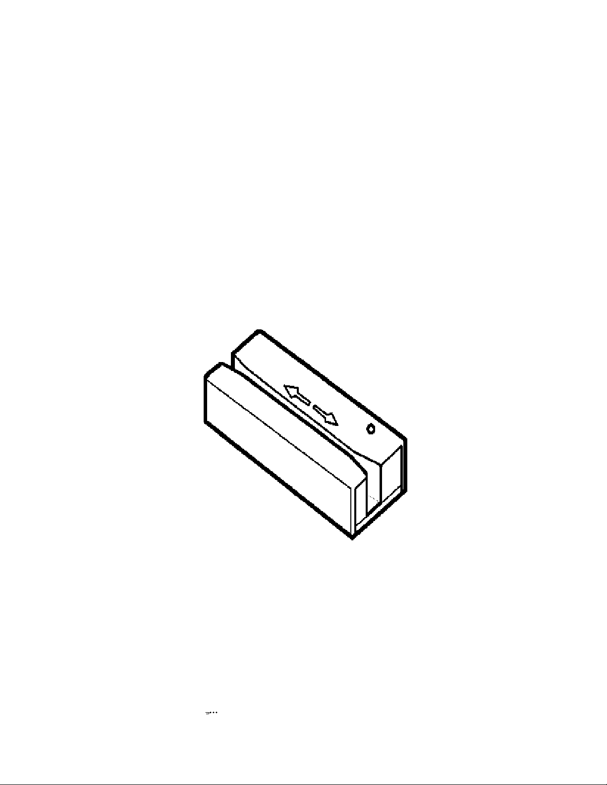
Operating The Card Reader
The Card Reader is designed to read all of the standard magnetic card formats. To read a card, insert the card in the
reader with the magnetic stripe facing the magnetic head in the Card Reader. The magnetic head is located on the same
side as the LED on the top of the Card Reader. Slide the card through the Card Reader slot, with a smooth stroke, in
either direction. When swiping the card through the Card Reader, the LED will turn off. Once you have completed swiping
the entire card through the reader, the Card Reader will then set the LED to either green (for good read) or red (for no
read). In addition to the green LED on a good read, the Card Reader will sound the buzzer to give you an audible
indication that the card was successfully read, and the data is being transmitted to the computer.
Using The Universal Programmer Software to Configure The
Card Reader
This programming software is used for configuring ID Innovations USB Magnetic Card Readers and Keyboard Wedge
(PS2 Style) Magnetic Card Readers. The main display of the Programmer allows you to view the settings of the
configuration in an abbreviated format. In this format you can see all settings that have been changed from default. Many
of the keyboard keys used to program the Keyboard Wedge (PS2 Style) Magnetic Card Readers can be used in the
Univseral Programmers software. This allows customers with existing Keyboard Wedge (PS2 Style) Magnetic Card
Readers to quickly become familiar with the Universal Programmers software. All settings available in the Keyboard
Wedge (PS2 Style) Magnetic Card Readers can be found within the Universal Programmer Software, for explanations of
each setting see page 11.
In addition to allowing you to configure the Magnetic Card Readers the Univeral Programmer Software can be used to
convert configuration of a Classic Line Reader for use in a Value Line Reader. Likewise you can take Value Line
Programming and use it to program a Classic Line Reader.
))
Note: To obtain a Free copy of the Universal Programmer software visit our Website at
www.idinnovations.com.
Using The Setup Mode To Configure The Card Reader (PS2
Style-Classic Line)
The Card Reader can be configured through the use of the computer keyboard. The Card Reader must be installed and
powered to enter the setup mode. Once the unit is powered up, press and hold the following keys:

Features
9
Left-Control, Caps Lock, Right-Shift
, and
Backspace
1
- or -
Left-Control, F1, Right-Shift
, and
Backspace
2
))
Note: To configure the Value Line Keyboard Wedge reader you will need to obtain a Free copy of the Universal
Programmer software from our Website at
www.idinnovations.com. However several hot key sequences are available
to configure the more frequently used options, see page 23 for more information.
Once you release the keys, the Card Reader will produce a series of beeps, change the LED to orange and display a
message similar to the following on your display:
F1-F10=Options, Use ARROW KEYS to Toggle/Move, ESC=Exit
To ensure that you have enough space on your command line for the Card Reader options to be displayed, we
recommend that you either have your command prompt located at the root directory, or that you load an editor with a new
file. This will allow the Card Reader to use most of the characters on your computer display. For example, in Windows
load Windows Write and in OS/2 load the Notepad program.
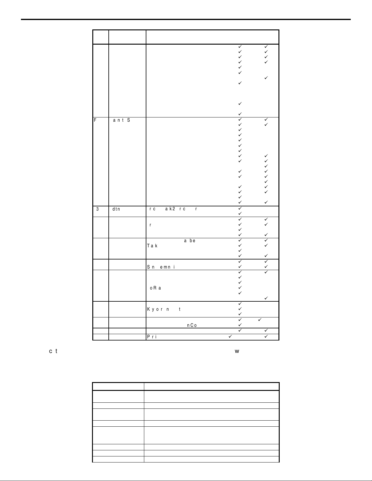
Setup is separated into many different categories ranging from "Interface" to "Cloning". The following is a list of function
keys and the setup category for which they apply:
1
This is a generic key sequence used to configure any ID Innovations' keyboard wedge device.
2
This key sequence is used to configure ID Innovations' keyboard wedge Magnetic Stripe Readers only.
Features
10
Key
Category
Options
Classic
Line
Value
Line
F1
Interface
Keyboard Country
Transmit Speed
CTRL/Special Char Delay
Send Numerics As
Setup Mode Lockout
Output Mode
OLE OPOS Mode
Serial (Baud Rate, Data Bits, Parity,
Duplex, Data Format, Inverted Output,
Intercharacter Delay, Caps Lock, Num
Lock)
Wand Emulation (Append Mode, Max
Segment Size, Segment Output Delay)
Firmware Version and Release Date
9
9
9
9
9
9
9
9
9
9
9
9
9
9
F2
Magnetic Stripe
Enable Tracks
Require Tracks
Data Output Mode (Track Data, Field Data)
Track Output Order
Field Output Order
EXP DATE Format
Expiration Date Separator Char
Send 6 Bit Field Separator '^' As
Send 4 Bit Field Separator '=' As
Send Track 2 Start Sentinel '%' As
Send Track 3 Start Sentinel ';' As
Send Track 3 Start Sentinel '%' As
Send Track 3 Start Sentinel '!' As
Send Start & End Sentinels
Send LRC Character
Send MSR Hardware Control Characters
No Read Output String
9
9
9
9
9
9
9
9
9
9
9
9
9
9
9
9
9
9
9
9
9
9
9
9
9
9
F3
Editing
Track1, Track 2, Track 3 Stripping
ACCT, NAME, EXP DATE Stripping
9
9
F4
Preambles
Magnetic Stripe Preamble
Track1, Track2, Track 3 Preamble
ACCT #, NAME, EXP DATE Preamble
Send Pre/Postambles For Unread Tracks
9
9
9
9
9
9
9
F5
Postambles
Magnetic Stripe Postamble
Track1, Track 2, Track 3 Postamble
ACCT #, NAME, EXP DATE Postamble
Send Pre/Postambles For Unread Tracks
9
9
9
9
9
9
9
F6
Termination String
Termination String
Send Termination String
9
9
9
9
F7
Buzzer/LED
Good Read Beep
Beep Tone
Beep Duration
No Read LED Delay
LED Power Save Mode
Power Up Beep
9
9
9
9
9
9
9
F8
Diagnostics
Firmware Version and Release Date
Keyboard Information
Show Scan Codes
9
9
9
F9
Cloning
Lockout Cloned Reader Setup Mode
Press ENTER To Begin Cloning
9
9
9
(hotkeys)
F10
Reset All Defaults
Reset All Defaults?
9 9
F11
Parsing
Parsing Options (see page xxx)
9
(upon request)
9
For those categories which have more than one option, the UP and DOWN arrow and ENTER keys are used to move from
one option to the next. In addition to the UP and DOWN arrow keys, the CTRL UP and CTRL DOWN arrow keys are used
to move to the bottom and the top of the list. The following is a list of all special editing keys and a description of their
function:
Key
Description
Left Arrow, Right Arrow,
Backspace & Space Bar
Toggles through the settings for the current option.
Up & Down Arrow
Moves from one option to the previous or next within the category.
CTRL Up & CTRL Down
Arrow
Moves to the top or bottom of the category.
Home & End
Moves to the beginning or end of an input field.
ALT Backspace
Toggles the output mode during configuration, between destructive
backspace and non-destructive backspace. Defaults to non-destructive
backspace.
CTRL + Keypad
Increases transmit speed during setup.
CTRL - Keypad
Decreases transmit speed during setup.
CTRL F7
Test the current Beep Tone and Beep Duration

Features
11
Key
Description
CTRL F10
Resets the current option to the default setting.
ALT F10
Resets all options in current category to default settings.
CTRL Escape
Exit configuration, saving changes.
ALT Escape
Exit configuration, without saving changes.
))
Note: If you experience some character loss during setup, you may press the CTRL-(Keypad Minus) key to slow
character transmission. To speed up character transmission, press the CTRL+(Keypad Plus) key.
))
Note: After 5 minutes of inactivity (no key presses) the Card Reader will exit setup mode and save all changes.
The following sections document all of the setup mode categories and the individual options within each category.
 Loading...