

ID Innovations Bar code Slot Reader User Manual
1
Bar Code
Slot Reader
for IBM AT, PS/2, USB and Compatible Keyboard Interfaces
ID Innovations Incorporated
ID Innovations Incorporated

2
ID Innovations Incorporated was founded in 1993 to provide low cost, high performance hardware and software
solutions for the identification market. This market is ever changing and continually growing, requiring products that
evolve and a manufacturer with an understanding of the market's needs. All of ID Innovations' products show our
commitment to engineering excellence and attention to detail. In order to improve our products and services, we
welcome any comments or suggestions that you may have. Our goal is to become your source for providing
solutions for your identification technology needs.
Mailing Address Shipping Address
ID Innovations Incorporated ID Innovations Incorporated
1244 Karla Drive Suite 104 1244 Karla Drive Suite 103
Hurst, TX 76053 Hurst, TX 76053
Tel (817) 285-8772
Fax (817) 285-8839
Copyright 1996-2007 by ID Innovations Incorporated. All Rights Reserved.
Revision 1.5 (08/07)
PRINTED IN THE UNITED STATES OF AMERICA

Copyright Information
The information contained in this manual is for informational purposes only and is subject to change without notice. The
contents of this manual are copyrighted. In addition, all software code in the ID Innovations Incorporated Bar Code decoder
itself is copyrighted. No part of this manual, or the ID Innovations Incorporated Bar Code decoder software, may be copied or
reproduced in any manner, or disseminated to any unauthorized person, without the prior written permission of ID Innovations
Incorporated.
LIMITATION OF LIABILITY
ID INNOVATIONS INCORPORATED LIABILITY FOR ANY DEFECTIVE PRODUCTS IS LIMITED TO THE REPAIR OR
REPLACEMENT OF THE PRODUCT AT OUR OPTION. ID INNOVATIONS INCORPORATED SHALL NOT BE LIABLE
FOR:
1. DAMAGE TO OTHER PROPERTY CAUSED BY ANY DEFECTS IN THIS PRODUCT, DAMAGES BASED UPON
INCONVENIENCE, LOSS OF USE OF THE PRODUCT, LOSS OF TIME, COMMERCIAL LOSS; OR
2. ANY OTHER DAMAGES, WHETHER INCIDENTAL, CONSEQUENTIAL OR OTHERWISE. SOME STATES DO NOT
ALLOW LIMITATIONS ON HOW LONG AN IMPLIED WARRANTY LASTS AND/OR DO NOT ALLOW THE EXCLUSION OR
LIMITATION OF INCIDENTAL OR CONSEQUENTIAL DAMAGES, SO THE ABOVE LIMITATIONS AND EXCLUSIONS MAY
NOT APPLY TO YOU.
3

Table of Contents
4
Table of Contents
Features ....................................................................................................................................................................... 6
Installation – MultiMode USB ....................................................................................................................................... 6
Keyboard Wedge................................................................................................................................................... 6
Virtual COM Port.................................................................................................................................................... 6
HID Mode............................................................................................................................................................... 7
Installation - Keyboard Wedge (PS2 Style).................................................................................................................. 7
Installation – Serial (PS2 Style).................................................................................................................................... 7
Installation - Wand Emulation (PS2 Style) ................................................................................................................... 7
Mounting The Slot Reader ........................................................................................................................................... 7
Operating The Card Reader......................................................................................................................................... 8
Using The Setup Mode To Configure The Decoder..................................................................................................... 8
Interface (F1) ......................................................................................................................................................... 10
Transmit Speed, 0=Fastest............................................................................................................................. 10
Keyboard Country ........................................................................................................................................... 10
CTRL/Special Char Delay (milliseconds) ........................................................................................................ 10
Send Numerics As .......................................................................................................................................... 11
Setup Mode Lockout ....................................................................................................................................... 11
Output Mode: .................................................................................................................................................. 11
Serial Baud Rate ............................................................................................................................................. 11
Serial Data Bits................................................................................................................................................ 11
Serial Parity ..................................................................................................................................................... 11
Serial Duplex................................................................................................................................................... 11
Serial Data Format .......................................................................................................................................... 11
Inverted Serial Output ..................................................................................................................................... 11
Serial Intercharacter Delay.............................................................................................................................. 11
Serial Caps Lock ............................................................................................................................................. 11
Serial Num Lock.............................................................................................................................................. 12
Decoders/Scanner (F2) ......................................................................................................................................... 12
DECODERS ON/OFF ..................................................................................................................................... 12
Code 39........................................................................................................................................................... 12
Code 128......................................................................................................................................................... 13
Interleaved 2 of 5 ............................................................................................................................................ 13
Codabar .......................................................................................................................................................... 14
OTHER............................................................................................................................................................ 14
Editing (F3) ............................................................................................................................................................ 15
Select Edit Number ......................................................................................................................................... 15
Strip Leading Characters.......................................................................................................................... 16
Strip Trailing Characters........................................................................................................................... 17
Filter Leading Characters ......................................................................................................................... 17
Filter Trailing Characters .......................................................................................................................... 17
Filter Characters ....................................................................................................................................... 17
Insert Leading Character .......................................................................................................................... 17
Insert Trailing Character ........................................................................................................................... 18
Convert To Upper Case............................................................................................................................ 18
Convert To Lower Case............................................................................................................................ 18
Macros/Special Keys (F4)...................................................................................................................................... 18
Select Macro Number ..................................................................................................................................... 18
Special Keys.................................................................................................................................................... 20
Strings (F5)............................................................................................................................................................ 20
Termination ..................................................................................................................................................... 21
Preamble......................................................................................................................................................... 21
Postamble ....................................................................................................................................................... 22
*** F6- Reserved For Future Use *** (F6).............................................................................................................. 22
Buzzer/LED (F7) .................................................................................................................................................... 22
Power Up Beep ............................................................................................................................................... 22
Good Read Beep Tone ................................................................................................................................... 22
Beep Duration ................................................................................................................................................. 22
No Read LED Delay ........................................................................................................................................ 22
LED Power Save Mode................................................................................................................................... 22
Status/Diagnostics (F8) ......................................................................................................................................... 22
Firmware Version and Release Date .............................................................................................................. 22

Table of Contents
5
Keyboard Information...................................................................................................................................... 22
Show Scan Codes........................................................................................................................................... 22
Cloning................................................................................................................................................................... 23
Lockout Cloned Reader Setup Mode .............................................................................................................. 23
Press ENTER To Begin Cloning ..................................................................................................................... 23
Reset All Defaults (F10)......................................................................................................................................... 23
Reset All Defaults?.......................................................................................................................................... 23
Exiting Setup Mode and Saving Changes ............................................................................................................. 23
Appendices................................................................................................................................................................... 24
Appendix A - Bar Code Symbologies .................................................................................................................... 25
&RGH
............................................................................................................................................................... 25
)XOO$6&,,&RGH
.................................................................................................................................................... 26
&RGH
.............................................................................................................................................................. 27
,QWHUOHDYHGRI
.................................................................................................................................................... 28
&RGDEDU
............................................................................................................................................................... 29
Appendix-B Special Characters............................................................................................................................. 30
Special Characters Table................................................................................................................................ 30
ALT Keypad Table........................................................................................................................................... 31
Appendix-C Decoder Pinouts and Specifications .................................................................................................. 32
Appendix-D Troubleshooting and Error Beeps...................................................................................................... 33
Troubleshooting .............................................................................................................................................. 33
Error Beeps ..................................................................................................................................................... 33
Index............................................................................................................................................................................. 35

Features
6
Features
The ID Innovations Incorporated Bar Code Slot reader represents the state of the art in keyboard wedge and bar code decoding.
The Bar Code decoder is based on ID Innovations Incorporated's True Wedge technology. The advances that True Wedge
technology provide are found in enhanced functionality, such as keyboard configurable parameters, self cloning, and auto Caps
Lock detection. Other features of the ID Innovations Incorporated Bar Code Slot reader include:
Simple installation, Keyboard Wedge, Serial
Superior keyboard wedge interface - NOVELL compatible - auto Caps Lock detection ensures that the data always
appears on the computer just the way it is encoded in the bar code
Simple programming from your keyboard - no need to flip switches or scan bar codes!
Over 100 configurable options
Automatically clones decoders in under 10 seconds - over 300 decoders per hour
Auto detection of the type of computer (PC, XT, AT, PS/2, and XWindow terminals with a PC compatible keyboard
interface)
Can be used with or without the keyboard
Supports over twenty different keyboard country layouts
Map bar code data to any key on the keyboard
Supports editing, operations include (Insert, Stripping, Filtering, Convert Case)
Macro support, replace a string in the bar code with another
Programmable preamble, postamble, and termination strings
READ/NO-READ indicators (buzzer and bright tri-color LED)
Superior reading performance utilizing advanced decoding algorithms
Extended ASCII support for Code 128 bar codes
Low power consumption
Compact size
Installation – MultiMode USB
The Slot Card Reader is available with a USB Adaptor cable that terminates in a Universal Serial Bus (USB) Type A connector.
Most new computers have multiple USB ports that can be used with a wide variety of peripherals. Simply plug the adaptor into an
available USB port and the PS/2 cable from the reader into the adaptor and the operating system will display a dialog box to guide
you through the installation process. The device driver that Windows will install for this device is the driver used for HID keyboard
devices and is part of the Operating System. In some installations Windows will locate all of the files it requires without requiring
any user intervention. However, sometimes Windows will request the location of the files it needs. In these cases you may need
to have your Windows Installation CD in order to complete the installation. Most of these type installations simply require you to
click on the
Next
and
Finish
buttons repeatedly.
The ID Innovations Incorporated USB Bar Code Slot Reader can be installed to output data in a variety of ways. No other Bar
Code Slot Reader on the market can match its versatility.
Installation – USB Keyboard Wedge (Default)
By default when you install the ID Innovations Incorporated Bar Code Slot Reader it will output Card Data as Keyboard keystrokes.
This allows host applications designed to acquire Card Data from keyboard input, to seamlessly receive data from the Bar Code
Slot Reader. This mode of operation requires no additional software drivers and is available on Windows, Linux and MAC
operating systems.
))
Note: A Windows
USB Accelerated keyboard driver
is available for Free download from our Website at
www.idinnovations.com for use with the ID Innovations Incorporated USB products. This driver will output Card Data 3 to 5
times faster than the standard windows keyboard driver. In addition, this driver will block the user from entering keystrokes
during transmission to ensure that Card Data is not corrupted and it will allow you to modify the data from the card reader even
further.
Installation – USB Virtual COM Port
If you have a POS application that requires, or can support, an RS232 Bar Code Slot Reader, you can use the ID Innovations
Incorporated USB Bar Code Slot Reader. In this mode, the Card Data will be output to a Virtual COM port on your system. Simply
select this COM port in your POS application and you will be up and running in no time.
))
Note: In order to use this feature you will need to download the Free software driver from our Website at
www.idinnovations.com

Features
7
Once you have downloaded and installed the software driver, you can create the Virtual COM port to be used by your POS
software. Simply install the driver icon in your startup folder on your computer and it will be loaded each time your computer is
powered up. When the driver is loaded all Card Data will be transmitted to the COM port and into your application.
))
Note: In most RS232 installations you have to match up the COM port settings of the Card Reader and POS software.
However, when using the ID Innovations Incorporated USB Virtual COM port driver you need not concern yourself with this
step. The driver will automatically present the Card Data in the proper Baud Rate, and Parity settings for your application.
Installation – USB HID Mode
The ID Innovations Incorporated Bar Code Slot Reader can be operated in several different modes. As explained above it can be
used in either a Keyboard Wedge or Virtual COM port mode of operation. In addition to these modes, you can interface to the Bar
Code Slot Reader using USB Human Interface Device (HID) Class specification Version 1.1 Windows API calls. In these modes
the Bar Code Slot Reader behaves like a vendor defined HID device so that a direct communication path can be established
between the Host application and device without interference from other HID devices.
The ID Innovations Incorporated Bar Code Slot Reader provides a serial HID interfaces. The serial interface can be used to
Sequentially receive Card Data in ASCII form in multiple 5 byte Input records. The format of the Card Data transmission is
dependent on the program settings of the Bar Code Slot Reader.
))
Note: For more information on either of these modes and program assistance in developing your applications contact ID
Innovations Incorporated.
Installation - Keyboard Wedge (PS2 Style)
The Slot Reader is installed between the computer and the keyboard. The keyboard cable is plugged into the Slot Reader using
the connector labeled "KB". The Slot Reader is then connected to the computer using the connector labeled "PC". The PS2-Y
cable is a wedge cable that has two 6 pin Mini-DIN connectors for both the keyboard and the PC.
Installation – Serial (PS2 Style)
To install the Slot Reader serially you will need a ID Innovations, Serial Converter. The Serial Converter is used to convert TTL
signal levels to RS-232 signal levels. The Serial Converter is readily available in a 9-pin straight cable configuration for direct
connection to PCs and a 25-pin Y cable configuration for connection between a Terminal and Host devices. When connecting the
Card Reader to the Serial Converter the PC side of the Card Reader cable should be connected to the 6-pin connector of the
Serial Converter. If you are connecting the Card Reader to a 25-pin Serial Converter, the 25-pin connector marked TERMINAL
should be connected to the Terminal side and the 25-pin connector marked HOST should be connected to the Host side. For
information on cable pin-outs see Appendix D
))
Note: Do not connect a keyboard to the Slot Reader when operating in Serial mode. If you have a keyboard connected to the
Slot Reader when power is first turned on, the Slot Reader will revert back to the Keyboard Wedge mode of operation. A
keyboard should only be connected to the Slot Reader after power is turned on, so that you may configure the Slot Reader
using the keyboard.
))
Note: If you have a device with a powered serial port, that provides +5v @75ma, you may connect the Slot Reader directly by
using a simple cable adapter and configuring the Card Reader for
Inverted Serial Output
, see I
nverted Serial Output
for
more information.
Installation - Wand Emulation (PS2 Style)
To install the Slot Reader in Wand Emulation mode you must first configure the Slot Reader for Wand Emulation and the proper
segment sizes. In this mode of operation, the Slot Reader can be plugged into the Wand port of a bar code decoder and the
decoded Card Data is transmitted as Code 128 bar codes. In order to connect the Slot Reader to the bar code port of a decoder
you may have to use a simple cable adapter, for information on cable pin-outs see Appendix D.
))
Note: Do not connect a keyboard to the Slot Reader when operating in Wand Emulation mode. If you have a keyboard
connected to the Slot Reader when power is first turned on, the Slot Reader will revert back to the Keyboard Wedge mode of
operation. A keyboard should only be connected to the Slot Reader after power is turned on, so that you may configure the
Slot Reader using the keyboard.
Mounting The Slot Reader

Features
8
The Slot reader can be mounted in one of two ways, using the Two Velcro
strips included or inserting screws into the four
threaded inserts on the bottom of the reader. However, if you choose to mount the unit using the threaded inserts, do not use a
long screw in the insert by the cable. There is a socket located above the insert that will be damaged by a long screw.
))
Note: It is recommended that you mount the Slot reader to avoid damaging the cable. Frequent bending of the cable can
break the wires within it.
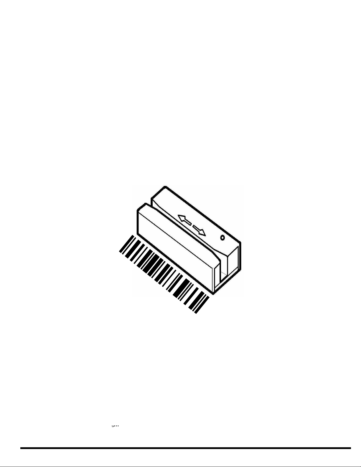
Operating The Slot Reader
To read a card, insert the card in the reader with the bar code facing away from the LED on the top of the slot reader. Slide the
card through the reader slot, with a smooth stroke, in either direction. When swiping the card through the slot reader, the LED will
turn off. Once you have completed swiping the entire card through the reader, the reader will then set the LED to either green (for
good read) or red (for no read). In addition to the green LED on a good read, the Slot reader will sound the buzzer to give you an
audible indication that the card was successfully read, and the data is being transmitted to the computer.
Using The Setup Mode To Configure The Reader
The Slot reader can be configured through the use of the computer keyboard. The reader must be installed and powered to enter
the setup mode. Once the unit is powered up, press and hold the following keys:
Left-Control, Caps Lock, Right-Shift
, and
Backspace
1
- or -
Left-Control, F3 Right-Shift
, and
Backspace
2
Once you release the keys, the Slot reader will produce a series of beeps, change the LED to orange and display a message
similar to the following on your display:
F1-F10=Options, Use ARROW KEYS to Toggle/Move, ESC=Exit
To ensure that you have enough space on your command line for the reader options to be displayed, we recommend that you
either have your command prompt located at the root directory, or that you load an editor with a new file. This will allow the reader
to use most of the characters on your computer display. For example, in Windows load Windows Write and in OS/2 load the
Notepad program.
1
This is a generic key sequence used to configure any ID Innovations' keyboard wedge device.
2
This key sequence is used to configure ID Innovations' keyboard wedge Bar Code decoders only.

9
Setup is separated into many different categories ranging from "Interface" to "Cloning". The following is a list of function keys and
the setup category for which they apply:
Key
Category
Options
F1
Interface
Transmit Speed
Keyboard Country
CTRL/Special Char Delay
Send Numerics As
Setup Mode Lockout
Output Mode
Serial Baud Rate
Serial Data Bits
Serial Parity
Serial Duplex
Serial Data Format
Inverted Serial Output
Serial Intercharacter Delay
Serial Caps Lock
Serial Num Lock
F2
Decoders/Scanner
Decoders On/Off
Code 39
Code 128
Interleaved 2 of 5
Codabar
Other
F3
Editing
Edit #1 - Edit #5
F4
Macros/Special Keys
Macro #1 - Macro #5
Keys
F5
Strings
String #1 - String #5
F6
Reserved
F7
Buzzer/LED
Power Up Beep
Good Read Beep Tone
Beep Duration
No Read LED Delay
LED Power Save Mode
F8
Status/Diagnostics
Firmware Version and Release Date
Keyboard Information
Show Scan Codes
F9
Cloning
Lockout Cloned Reader Setup Mode
Press ENTER To Begin Cloning
F10
Reset All Defaults
Reset All Defaults?
For those categories which have more than one option, the UP and DOWN arrow and ENTER keys are used to move from one
option to the next. In addition to the UP and DOWN arrow keys, the CTRL UP and CTRL DOWN arrow keys are used to move to
the bottom and the top of the list. The following is a list of all special editing keys and a description of their function:
Key
Description
Left Arrow, Right Arrow
Toggles through the settings for the current option.
Up & Down Arrow
Moves from one option to the previous or next within the category or group.
CTRL Up & Down Arrow
Moves to the top or bottom of the category or group.
Home & End
Moves to the beginning or end of an input field.
ALT Backspace
Toggles the output mode during configuration, between destructive backspace and
non-destructive backspace. Defaults to non-destructive backspace.
CTRL + Keypad
Increases transmit speed during setup.
CTRL - Keypad
Decreases transmit speed during setup.
CTRL F7
Test the current Beep Tone and Beep Duration
CTRL F10
Resets the current option to the default setting.
SHIFT F10
If you are in a category with groups (F2-F5), SHIFT F10 resets the current group. If
you are in a category without groups (F1, F7-F10), SHIFT F10 resets the entire
category.
ALT F10
Resets all options in current category to default settings.
CTRL Escape
Exit configuration, saving changes (Permanent).
ALT Escape
Exit configuration, without saving changes.
))
Note: If you experience some character loss during setup, you may press the CTRL-(Keypad Minus) key to slow character
transmission. To speed up character transmission, press the CTRL-(Keypad Plus) key.
))
Note: After 5 minutes of inactivity (no key presses) the decoder will exit setup mode and save all changes.
Features

10
The following sections document all of the setup mode categories and the groups and individual options within each category.
Next to the option name is the default setting for the option. In addition to the default setting, the keys that are used for editing are
listed to the right of the option name. The meaning of each of the key icons is as follows:
Key Icon
Meaning
Left Arrow & Right
Arrow
The left and right arrow keys scroll through available settings for the option.
Alt Keypad
An ALT keypad sequence may be used to enter characters for the setting.
ASCII
All ASCII data is valid for the option. All characters are available for entry into the
field.
GROUP
Used to indicate that the option represents a group of sub-options. The left and right
arrows scroll through the list of option groups. After selecting the option group, up
and down arrows are used to configure the sub-options.
OPERATION
Used to indicate that the option represents an edit operation and that all of the
options listed below it are specific to that operation until the next operation is defined.
STRING TYPE
Used to indicate that the option represents a string type and that all of the options
listed below it are specific to that type of string until the next string type is defined.
Interface F1
Transmit Speed, 0=Fastest: 0
The Transmit speed option is used to control the speed at which bar code data is sent to the computer. In some instances the
reader may overrun the computer if this setting is too fast, or if the computer is busy performing some lengthy operation. This
option ranges from 0 to 99, with 0 being the fastest and 99 being the slowest.
Keyboard Country: UNITED STATES
The Keyboard Country option is used to inform the Slot reader of the keyboard country that should be used when transmitting bar
code data. The reader supports 26 different settings (PC compatible layout) for the Keyboard Country, ranging from "Belgium" to
"Universal". It is important to note that changing this setting and not changing your computer to the same setting will result in
garbled or lost characters. The settings for this option are as follows:
BELGIUM
GERMANY
SLOVENIA
BRAZIL
HUNGARY
SPAIN
CANADIAN-FRENCH
ITALY
SWEDEN
CROATIA
LATIN AMERICA
SWITZERLAND
(FRENCH)
CZECHOSLOVAKIA (CZECH)
NETHERLANDS
SWITZERLAND
(GERMAN)
CZECHOSLOVAKIA (SLOVAK)
NORWAY
UNITED KINGDOM
DENMARK
POLAND
UNIVERSAL
FINLAND
PORTUGAL
UNITED STATES
FRANCE
SERBIA/YUGOSLAVIA
))
Note: If you set the
Keyboard Country
to BELGIUM, FRENCH, or GERMANY, then numeric data is sent faster by setting the
Send Numerics As:
option to NUMERIC KEYPAD KEYS.
a series of ALT keypad sequences. For example, to transmit an "A" to the computer, the reader performs the ALT 065 key
sequence on the numeric keypad. It is important to note that this method of communication may not work with your computer
hardware and software. It is possible that no data will appear on your computer if you set the Slot reader to output in this mode. If
this is the case, you will have to reenter the setup mode and press F1, ALT F10 and CTRL ESC. This will reset the Interface
category and reset the Keyboard Country back to the UNITED STATES default setting.
))
Note: In order for the
Keyboard Country
changes to take effect, you must exit the setup mode and save changes.
CTRL/Special Char Delay (milliseconds): 50
The CTRL/Special Char Delay is the amount of time the Slot reader will delay after sending a special character or a CTRL key
sequence before sending the next character of data. This option ranges from 0 to 255 milliseconds. The characters that are
affected by this option are those that are non-printable. For a complete list of the characters, refer to Appendix-B, Special
Characters Table. This feature is used to prevent overrunning the keyboard buffer when sending function keys and other non-data
characters.
Features

Features
11
Send Numerics As: MAIN KEYBOARD KEYS
This option is used to indicate which numeric keys you want the reader to use when transmitting bar code data to the computer. If
this option is set to MAIN KEYBOARD KEYS, then all numeric data will be sent as numerics on the main keyboard. If this option is
set to NUMERIC KEYPAD KEYS, then all numerics will be sent from the numeric keypad.
Setup Mode Lockout: OFF
This option is used to allow you to lock out the setup mode until the unit is turned off and then powered back on. Once this option
is activated and a bar code is read, the setup mode will be locked out. This feature is used to prohibit unauthorized changes from
being made to the reader's setup parameters.
Output Mode: KEYBOARD WEDGE
This option is used to specify the output mode of the reader. This option may be set to KEYBOARD WEDGE and SERIAL.
KEYBOARD WEDGE
In Keyboard Wedge mode the reader will automatically detect the keyboard protocol of the host computer. The reader should be
installed as specified in the
Installation - Keyboard Wedge
section of this manual on page 8.
SERIAL
In Serial mode the reader will transmit all data serially using the Serial settings below. In order for this mode typically requires you
to use a Serial Converter, for more information see
Installation - Serial
on page 8. Plugging the Slot Reader into a PC or
TERMINAL with a keyboard attached places the reader in keyboard wedge mode, so that you may permanently change the Output
Mode.
))
Note: Prior to setting the
Output Mode
to
SERIAL
and connecting the decoder serially, configure all of the Serial settings to
match your serial device. If you do not properly match the settings, the decoder will not output the data properly.
Serial Baud Rate: 9600
This option is used to control the speed of the serial communications. This option may be set to 300, 600, 1200, 2400, 4800,
9600, 19200, or 38400.
Serial Data Bits: 8
This option is used to control the number of Data Bits used for each character of serial data. This option may be set to 7, or 8.
Serial Parity: NONE
This option is used to control the Parity of the serial data that is transmitted. This option can be set to NONE, ODD, EVEN, MARK,
or SPACE.
Serial Duplex: FULL
This option controls the transmission of the serial data to the Terminal side of the Serial Converter. If this option is set to FULL,
serial data is only transmitted to the HOST side of the serial connection. If this option is set to HALF, serial data is transmitted to
both the HOST and the TERMINAL sides of the serial connection.
Serial Data Format: ASCII
This option is used to set the format of the data when it is transmitted serially. With the default setting all data is transmitted as
ASCII characters. If you set this option to SCAN CODES (PCTERM), all data is transmitted as scan codes. For example, the
letter A would be transmitted as the scan code for the key on the keyboard that is used to generate the letter A.
))
Note: The
Keyboard Country
setting effects the scan codes that are transmitted serially. Make sure that the
Keyboard
Country
setting matches the Keyboard that you would normally use.
Inverted Serial Output: OFF
This option is used to control the format of the transmitted serial data. If you are directly connecting the decoder to a serial device
with a powered serial port and are not using a Serial Converter, set this option to ON.
Serial Intercharacter Delay: 1
This option is used to control the amount of delay between each of the characters transmitted serially. This option is specified in
Milliseconds and ranges from 0 to 50.
Serial Caps Lock: OFF
When the Serial Data Format is set to SCAN CODES (PCTERM), this option controls the scan codes that are generated for the
NUMERIC KEYPAD KEYS. When the Serial Data Format is set to ASCII this option has no effect.

Features
12
Serial Num Lock: ON
When the Serial Data Format is set to SCAN CODES (PCTERM), this option controls the scan codes that are generated for the
alpha keys. When the Serial Data Format is set to ASCII this option has no effect.
Decoders/Other F2
Select Option Group: DECODERS ON/OFF GROUP
This group of options is used to quickly enable and disable individual bar code decoders. Cursoring down into this group and using
the left and right arrows, allows you to enable and disable each of the following decoders: CODE 39, CODE 128, INTERLEAVED 2
OF 5, and CODABAR.
Select Option Group: CODE 39 GROUP
Select this option group to modify the individual settings for the CODE 39 decoder. Once you have selected this option group, you
may cursor down to configure each of the following decoder options.
CODE 39: Decoder: ON
Use this option to enable or disable the CODE 39 decoder. The default for this option is ON.
CODE 39: Full ASCII: OFF
The CODE 39 symbology by default can encode the 26 upper case letters (A-Z), 10 digits (0-9), and 7 special characters (SPACE . + $ / %). Full ASCII CODE 39 is an extension of CODE 39 that can encode the full 128 ASCII character set. This is
accomplished by using two character sequences of characters from the standard CODE 39 character set. Enabling this option will
allow the decoder to properly read Full ASCII CODE 39 bar codes. With this option disabled (Default), Full ASCII bar codes cannot
be read properly.
))
Note: You cannot properly read both CODE 39 and Full ASCII CODE 39 bar codes at the same time. Since Full ASCII CODE
39 is an extension of standard CODE 39, the decoder must be used to read one or the other at any given time.
CODE 39: Check Digit: OFF
For applications requiring enhanced data security, a Modulo 43 check digit can be used on CODE 39 and Full ASCII CODE 39 bar
codes. When used, the check digit immediately follows the last data character. Use this option to enable or disable the check digit
requirement for CODE 39 bar codes. When the Slot reader decodes a CODE 39 bar code it will calculate the Modulo 43 check
digit and verify it against the decoded data.
CODE 39: Send Check Digit: OFF
Some applications may require that you use a check digit in the bar code for security but do not require the check digit be
transmitted to the computer. Use this option to have the decoder either send the check digit to the computer or remove the check
digit from the transmitted data.
CODE 39: Send Start/Stop Chars: OFF
Use this option to configure the decoder to transmit the CODE 39 Start/Stop characters to the computer. The default for this
option is OFF, to not transmit Start/Stop characters.
CODE 39: Maximum Length: 49
CODE 39: Minimum Length: 0
Use these options to configure the minimum and maximum lengths of CODE 39 bar codes that can be read. If you configure the
Maximum Length to 10 characters and the Minimum Length to 5 characters, the decoder will not read CODE 39 bar codes with
less than 5 characters and more than 10 characters. When calculating length requirements, do not include any Start/Stop
characters.
CODE 39: Type ID: a DEC 97 HEX 61
Use this option to configure the Type ID for the CODE 39 bar code. If the Full ASCII option is enabled then this Type ID is used as
the Type ID for Full ASCII CODE 39 bar codes. Sometime it may be necessary to transmit a Type ID for the type of the bar code
that was just read, this will allow a system to determine what to do with the data for the bar code. For example, CODE 39 bar
codes could be used for employee identification purposes and UPC bar codes could be used for product codes. The Type ID for
CODE 39 and UPC bar codes would be different allowing the system to automatically use the information in the appropriate
modules. Type ID's can be transmitted as a prefix or a suffix to the bar code data, for more information see
OTHER: Send Bar
Code Type ID
on page 15.
 Loading...