

Page 1
Steering Column to Steering Box
Installation Instructions
for Tri-Five Chevrolets
FOR PART NUMBER’S: 1120550010, 1120550020, 1120550051,
1070550030, 1070550040, 1120570010, 1120570020, 1120570010,
1070570030, 1070570040, 1140550010, 1140550020, 1140550051,
1150550030, 1150550040, 1160550010, 1160550020, 1160550051,
1140570010, 1140570020, 1140570051, 1150570030, 1150570040,
1160570010, 1160570020, 1160570051
www.ididitinc.com
610 S. Maumee St., Tecumseh, MI 49286
PH: (517) 424-0577 FAX: (517) 424-7293
Instruction # 8000000000 REV 1/14
Page 2

Thank you for purchasing the Tri-Five Chevy column from ididit.
This is a simple overview of how to mount your column. Any steering
column must be secured at the dash and rewall. This column will use
all the original mounting brackets at the dash. If you are missing parts,
some are available from Ecklers, or Danchuck. Both have web sites to
visit if necessary.
In these instructions we assume either the original gear box or an
aftermarket box are mounted in the original position. Since the gear box
is so close to the rewall, only a coupler (manual) or rag joint (power)
are necessary. If you have done a frame off restoration, the distance
may have changed between the body and the frame. Remember, the
steering column is one of the few parts that relate to both body and
chassis. If the body is placed slightly back from the original position,
you may need to add an inch to the column. We will be happy to
exchange this column (in original condition). We cannot be responsible
for body placement.
If you have added a rack and pinion front end, the installation will
require 2 joints and a shaft to reach the rack. This would be more of
a “hot rod” installation than a restoration. Both are great additions to
updating your steering.
It is highly recommended that you t your column before painting
it. Test tting now will save you a headache later on. We are not
responsible for paint.
1
Page 3
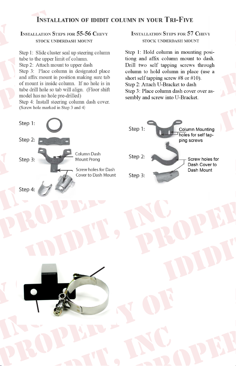
The Classic Chevy Floor Mount is made up of two pieces:
A.) T-shaped L Bracket
B.) Clamp
The T shaped bracket mounts in the original bolt holes in the inside oor
of your Chevy. The long extension
B.
comes forward toward the driver.
The clamp should slide up the tube
of the steering column. The steering column then slides above the
extension and through the oor
board. The clamp will slide over
A.
the extension of the oor bracket
and around the column. Your col-
umn is now secured to the oor to prevent any movement. Tighten all
fasteners when you are comfortable with the installation.
2
Page 4
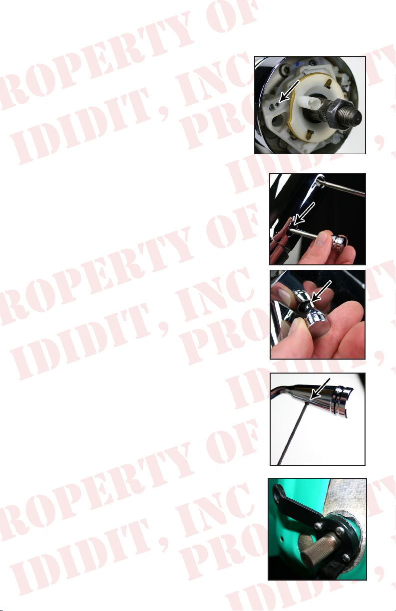
Turn Signal Lever:
The turn signal lever is located closest to the top of the column. With the steering
wheel and adaptor removed, look down at the top of
the column and on the left side you will see a round
screw hole. This secures the lever to the column.
Insert the lever onto the turn signal switch and insert
the provided screw into the screw hole (not D shaped
hole). Use a #2 Phililps screw driver to tighten the
screw until the lever is no longer loose, the screw
will not rub on the brass piece of the white horn cam.
Tilt Lever:
Located directly below the turn signal lever will be the
treaded hole for the tilt lever. Simply screw the tilt lever
into this hole.
Emergency Flasher Knob:
The Emergency asher is threaded into the hole
located on the right side of the column. You will
noticed the plastic portion that the asher screws
into is ush with the outer surface when the ashers
are in the off position. It is easy to accidently turn
the ashers ON while installing which could lead to
problems later. Check to make sure the ashers are in
the OFF position before continuing.
If Column Shift Application:
Place column shift knob onto the shift lever. Once on,
use setscrew (provided) and adjust knob so setscrew
is pointing towards the oor, tighten setscrew. Do not
remove the upper shift lever for any reason! The tension
spring will pop out and it is very difcult to re-install.
Column Shift Linkage Installation:
At the bottom of your column you will notice a lever.
This is the shift lever where your linkage will attach
from the column to the transmission. Note the 5/16
hole through the bushings, most kits use a 5/16 bolt
to secure the rod to the column. Please follow the kit
instructions for the linkage, but make sure that no part
of the kit hits the metal portion of the lever, as it will
create a rattle in the column.
3
Page 5
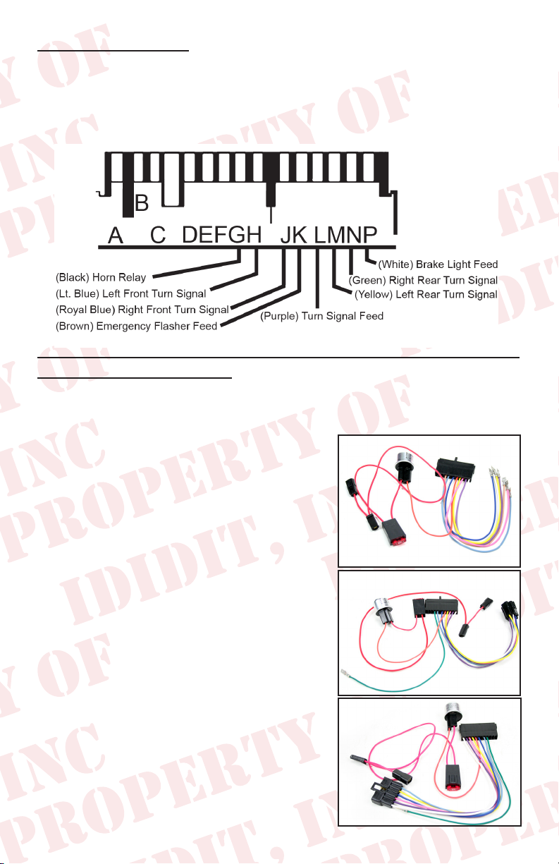
Wiring your Column
This ididit steering column uses a standard 3 7/8-inch male connect. However,
some GM columns use a 4 ¼-inch male connector. Connectors do not inter-
change and must be used in pairs. A mate to the 3 7/8 inch plug is available
through ididit. If you need to change this connector for any reason the following schematic will be helpful.
If you have an Original Wiring Harness and you want 4-way ashers
this information is for you!
All Tri-Five wiring systems are different and each one has different set of plugs.
We have kits available for each year. Follow the specic wiring schematics for
each 4-way kit instructions.
If you have a 1955 Chevy (PN # 3100035775)
The picture to the right depicts what the wire
harness will look like.
If you have a 1956 Chevy (PN # 3100035780)
The picture to the right depicts what the wire
harness will look like.
If you have a 1957 Chevy (PN # 3100035785)
The picture to the right depicts what the wire
harness will look like.
If you have an aftermarket wire harness the 4-way ashers
should already be integrated in the new wiring system.
4
Page 6

Horn Button Wiring:
A horn may require two wires to properly function
with an ididit column. The center lug on the button
should connect to a horn wire, which is provided by
ididit with your steering column. This horn wire will
slide into the horn cam (white plastic tube sticking up
on the top of the column). If there is a second wire off
to the side it is probably a ground wire (check with
the horn button manufacturer to be sure). This is normally used when an oring is used to hold the button in place. The o-ring does not provide sufcient
ground, therefore, an additional wire is provided to ground the horn button. If
there is not a hole in adaptor to ground to, use one of the puller holes with a
short bolt to attach the wire to the adaptor.
Column Shift stock gauge cluster applications: The “Z” wire
The wire between your column and gauge cluster is called the “Z” wire. The
“Z” wire links the column and original dash indicator together to ensure you
are in the correct gear, ididit column shift columns are designed to use this
original piece. At the top of tube on the ididit column you will see a rectangular space and what looks to be a hook inside the space, that is where the “Z”
wire hooks to. To hook the “Z” wire to your new ididit column, put the column
in neutral and route the “Z” wire through the hook on the ididit column. The
“Z” wire may need to be shortened or elongated to accurately get the column
and indicator aligned, the best way to do this is to test its function before rein-
stalling the chrome piece on your cluster. Once you have tested the function of
the “Z” wire installed on the column you can continue your installation.
5
Page 7

Synchronizing your Column
In order to insure proper functioning, this steering column must be installed in
sync with the rest of the steering system. Turn signal cancellation and wheel
position, as well as smooth steering operation depends on it. Although not all
of them may need adjustment, the complete table of steps required for full
synchronization is as follows:
1. The front wheels must be pointing straight forward with the steering toe
set reasonably close.
2. Rotate the input shaft of the gearbox or rack from lock to lock and set the
box exactly half way between. For example, if the shaft rotates three full
turns from lock to lock. The center will be at 1½ turns from either locked
position.
3. Install the steering arm and drag link, and adjust tie rod ends to get the drag
link to t without moving either the box/rack or the front wheels. Rotating
each tie rod end the same number of turns will preserve adjustment.
4. (When using a Rack & Pinion #4 may apply) With the column mounted
in position and two joints are used on
a shaft, the forks of the yokes closest
to each other should be in line, or “in
phase”. Premature wear or binding
can result if the u-joints are not phased
properly. Sometimes if the u-joints are
at a severe angle, even if they are phased
correctly, a hard spot in the steering may occur for no apparent reason. If
this happens, index the u-joints two or three splines in one direction. The
hard spot should disappear or be minimized.
5. Install the shaft or joint on the gear box/rack. Leave the upper part of the
shaft unconnected for the time being.
6. Position the column housing so that the signal switch arm is level to the
left hand side.
7. Install the column through rewall, into your joint.
8. To achieve proper
synchronizing of your
column the nished
installation of your
column should look
like the diagram on the
right. If post on horn
cam is not at 10:30,
turn it until it is in the
10:30 position. Once
completed, your column will be in sync.
6
Page 8

Furnished on ALL Column Shifts
Accessories Important to Installation:
#2401400010 Classic Chevy Floor Mount
This oor mount bolts through the oor in the original holes. It stands up off the
oor within the original oor mount opening. Quick and easy installation.
#3100035785 1957 Chevy Wiring Adaptor for stock wiring
#3100035780 1956 Chevy Wiring Adaptor for stock wiring
#3100035775 1955 Chevy Wiring Adaptor for stock wiring
These are wiring harness adaptors from the plug on the steering column to the original plug
under the dash. They change the conguration and have a asher installed to convert your
parking lights to four way ashers. They are YEAR sensitive…be sure to order the correct
year for your vehicle!
7
Page 9

How to make a DD Shaft
The shaft of the gearbox will now need to be cut into a DD shaft. This
is a round shaft with ats centered on two sides. An easy way to do this
is to make a paper template. Create your own template by using the
measurements from the diagram below.
1.000”
.395
.945
1.525
2.075
2.356
Starting from an 1/8 from the bottom, wrap the
paper template around the shaft and match the
horizontal arrows together.
Mark the shaft at the 8 vertical arrow points
and draw a line down the length of the shaft,
connecting the marks. This will create the shaded
“D” sections found on the template.
With a grinder or similar tool, grind at the
shaded “D” sections to match the DD shaft. As
you work, use the coupler as a guide and test t to
ensure proper tting.
Another option would be to remove the gearbox
and take it to your local machine shop to be
modied.
8
Note: Diagram not to scale
Original Shaft
New DD Shaft
To make 3/4 DD shaft
remove .100” from
opposite sides of the shaft
Page 10

InstallatIon InstructIons for the classIc 1955-56-57
chevy – tIlt steerIng wIthout column shIft, usIng
stock gear Box
3/4” DD x 1” DD coupler, this coupler will be held to the column
with two set screws, installed at a 90° angle to each other.
The coupler is pre-welded the 1” DD side to
go on the column, two at sides ground onto
stock 3/4” shaft (coming out of gear box) to
make it 3/4” DD to t into other side of coupler
TILT COLUMN WITHOUT SHIFTER
1” DD SHAFT FROM THE
NEW STEERING COLUMN
ORIGINAL STEERING
SHAFT MADE IN TO
A 3/4” DD BY GRINDING TWO FLATS.
Column
3/4” DD TO 1” ADAPTOR
PART #3000315249
Note: Cut approximately 6” up from
the box, a second cut will be necessary.
Install the column after you cut the
shaft so both shafts are touching. If
you need to cut the steering box shaft to
move the column in more, cut it again
and recheck. Install any dash pieces
before cutting. After cutting to the
perfect length grind the shaft to a DD
to t the coupler. (See “Synchronizing
Your Column” on page 5.)
9
5
Page 11

InstallatIon InstructIons for the classIc 1955-56-57
chevy – tIlt steerIng wIth column shIfter, usIng
stock gear Box
A 3/4”-36 x 3/4” DD coupler will be held
to the column with set screws. The 3/4”-36
end will t on the column shaft.
TILT COLUMN WITH SHIFTER
3/4” 36 SHAFT FROM THE
NEW STEERING COLUMN
ORIGINAL STEERING
SHAFT MADE IN TO A
3/4” DD BY GRINDING
TWO FLATS
Column
3/4” DD TO 3/4” 36 ADAPTOR
PART #3000313449
Note: Cut approximately 6” up from
the box, a second cut will be necessary.
Install the column after you cut the
shaft so both shafts are touching. If
you need to cut the steering box shaft to
move the column in more, cut it again
and recheck. Install any dash pieces
before cutting. After cutting to the
perfect length grind the shaft to a DD
to t the coupler. (See “Synchronizing
Your Column” on page 5.)
10
Page 12

InstallatIon InstructIons for the classIc 1955-
56-57 chevy – tIlt steerIng wIth column shIfter
to the 605 steerIng Box
Once you have the box mounted in position, a rag joint
is used to connect it to your new column. This is a direct
hook-up. This column uses a 3/4” 36 shaft so a 3/4” 36
3/4” 30 splined rag joint is used. Both shafts are secured to
the rag joint with the supplied set screws.
TILT COLUMN WITH SHIFTER
3/4” 36 SHAFT FROM THE
NEW STEERING COLUMN
ORIGINAL 605 STEERING SHAFT 3/4” 30
Column
3/4” 30 TO 3/4” 36
RAG JOINT
PART #3000053431
11
Page 13

InstallatIon InstructIons for the classIc 1955-
56-57 chevy – tIlt column to the 605 steerIng
Box
Once you have the box mounted in position, a rag joint
is used to connect it to your new column. This is a
direct hook-up. The tilt column uses a 1” DD shaft
so a 1” DD x 3/4”-30 splined rag joint is used. Both
shafts are secured to the rag joint with the supplied set
screws.
TILT COLUMN WITHOUT SHIFTER
1” DD SHAFT FROM THE
NEW STEERING COLUMN
Column
1”DD TO 3/4” 30
RAG JOINT
PART #3000055231
ORIGINAL 605 STEERING SHAFT 3/4” 30
12
Page 14

These are the parts that will correspond to the particular installation that you are
doing. This will speed up the ordering process when the time comes.
#3000315249 3/4” DD x 1” DD Coupler
#3000313449 3/4” 36 Spline x 3/4” DD Coupler
#3000055231 1” DD x 3/4” 30 Spline Rag Joint
#3000053431 3/4” 36 Spline x 3/4” 30 Spline Rag Joint
#2612000010 ’55-57 Horn Kit
#2612100040 ’55-57 Horn Kit with Ring
steerIng wheel modIfIcatIons for 1955-56-57
chevys wIth stock steerIng wheel mounted on
steerIng column
The spline in your stock steering wheel is the
same as the one on the new column, so no
modications are needed here.
INSTALL THE
OPTIONAL
ADAPTOR
TRIM RING
Turn the wheel over and nd two screws that
hold a metal tab to the wheel. This tab is what
is used to cancel your turn signals. Remove
the two screws and the tab as you will not be
using them with your new column.
You will have to drill a 1/2” diameter hole in
REMOVE THE
CANCELLING
CAM
the wheel 3/4” from the center of the splined hole
in the center of the steering wheel at 45° (looking
at the front of the wheel). If this can’t
be done because of screw holes for a
puller, try to get the hole as close as
possible on either side. Do not drill
out puller holes, you may need them
later to pull the wheel. Install horn
kit, if purchased. If the horn kit with
ring is purchased, the ring is to be
siliconed onto the steering wheel. If
it doesn’t t on exactly right, use a
le or die grinder to trim inside.
NEW 1/2”
HOLE @ 45°
45°
3/4”
NEW CANCEL CAM
ASSEMBLED IN
NEW COLUMN
NEW SPRING
NEW CONTACT PIN
NEW
CONTACT
RETAINER
Next, install the wheel on the column.
If it doesn’t want to go on at rst,
move the horn cam with your thumb
and index nger a little one way or
the other until the wheel drops down
fully. This horn cam is what cancels
the turn signals, so with this horn
cam at 10:30, the steering box half
way between full left and right, and
the road wheels pointed straight ahead, the turn signals will cancel at the right time.
13
Page 15

steerIng column and wheel adaptor
comparIsons
After market steering wheel with the short
adaptor on the new column with shift and tilt
After market steering wheel with the short
adaptor on the new column with tilt and no
shift
After market steering wheel with the short
adaptor on the new column with shift and no
tilt
After market
steering wheel
with the short
adaptor on the
original column
2.063
.438
.813
O.E.
CENTER
LINE
1.25
2.5
O.E. steering wheel on the
new column with shift and
tilt
O.E. steering wheel on the
new column with tilt and
no shift
O.E. steering wheel on the
new column with shift and
no tilt
14
Original
equipment
steering
wheel
center line
on the
original
column
O.E.
CENTER
LINE
Page 16

Think you may have forgotten something?
Here’s what you may have missed:
Add Ons: (Add Ons should be installed on the column prior to shipment)
Cruise Control: Carbureted Engine or Fuel Injected Engine?
Dimmer or Wiper: Dimmer/Wiper Kits will replace the original knobs and
levers that come standard on an ididit column. This is a replacement lever
with a push button at the end of the knob. The Dimmer/Wiper kit when pushed
is either On or Off. Includes relay kit.
Accessories:
Steering Wheel: We cannot recommend any brand of wheel because there
are so many to choose from. If you are having a hard time guring out if
a wheel you had purchased will work with an adaptor or an ididit column,
simply give us a call.
Steering Wheel Adaptor: Unless using original 1969 & Up Steering
Wheel you will need an adaptor. The adaptor may depend on the wheel. ididit
recommends purchasing the Steering Wheel prior to purchasing the adaptor. 3,
5, 6 or 9-Bolt Adaptors are Available with nishes of Chrome, Black Powder
Coated, Brushed or Polished Aluminum. The adaptors are available with or
without Horn Buttons.
Floor Mount: Like the under dash mount this piece is very necessary when
installing your steering column safely. ididit offers a Classic Floor Mount,
Swivel Ball Floor Mount, Adjustable Floor Mount with or without a trim
piece. Available for any ididit Steering Column.
Shift Indicator: Shift indicators available are 3 or 4-speed transmissions.
ididit also carries shift indicators for Ford AOD & AODE transmissions. The
indicators are acrylic and can be ordered with or without the housing. The
housing nishes include: Chrome, Black Powder Coated, Brushed or Polished
Aluminum.
Accessory Knobs for Levers or Dash: Deco or Retro knobs are available
to replace the standard knobs that come standard on the column or if you plan
on matching those knobs to your dash knobs. Deco knobs are only available
in Polished Aluminum. Standard and Retro Knobs are available in Chrome,
Black Powder Coated, Brushed or Polished Aluminum.
Cable Shift Linkage Kit: Kits are not available for the 1955-57 Chevy
unless a Rack & Pinion is used and the column is length at least 2”.
15
Page 17

Notes:
16
Page 18

No part of this guide may be reprinted, reproduced or utilized in any
form without the express written permission of ididit, inc.
2009 ididit, inc.
All Rights Reserved
Printed in the USA
ididit, inc.
610 S. Maumee St., Tecumseh, MI 49286
(517) 424-0577 • (517) 424-7293 fax
www.ididitinc.com
 Loading...