

Page 1
Retrot Steering Column
Installation Instructions
for 1974-77 Bronco
For Part #’s: 1130845010, 1130845020, 1130845051, 1130845910,
1130845920, 1130845951, 1130855010, 1130855020, 1130855051,
1130855910, 1130855920, 1130855951, 1170845020, 1170845051,
1170845910, 1170845920, 1170845951, 1170855010, 1170855020,
1170855051, 1170855010, 1170855020, 1170855051
www.ididitinc.com
610 S. Maumee St., Tecumseh, MI 49286
PH: (517) 424-0577 FAX: (517) 424-7293
Instruction # 8000000075 REV 03/11
Page 2
Images or examples in this booklet may vary from your specic installation.
(A)
(B)
(C)
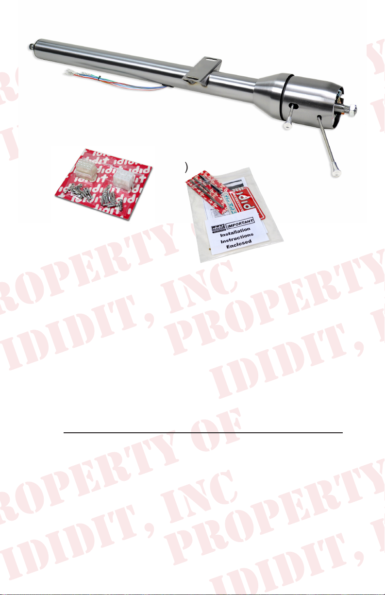
These are the components that come with the column.
(Paintable Steel column pictured above)
(A) Column
(B) Wiring Plugs with Terminals
(C) Instructions & Dress Up Kit (Dress Up Kit installed on this column)
We will work through this installation using all the above parts. For
instruction purposes we will assume the vehicle is all original and
uses the OEM harness.
Note: A 1974-75 Bronco will require a NEW 3/4” 36 half rag joint
(Part Number: 3000383400) to connect to the OE Rag Joint.
INDEX
REMOVAL.................................................................... 1 & 2
INSTALLATION OF COLUMN..........................................3-5
ELECTRICAL INSTRUCTIONS...........................................3
INSTALLATION OF KNOBS & LEVERS..............................5
WHEEL INSTALLATION......................................................5
Images or examples in this booklet may vary from your specic installation.
Page 3
REMOVAL of OEM Column: Disconnect positive battery cable.
Before you start your installation verify that your turn signals, brake
lights, horn & 4-way ashers are working properly. If they all function
now, then they should function properly again once the installation is
complete.
Verify that your steering wheel and driving wheels are straight.
Disconnect the positive terminal on the battery.
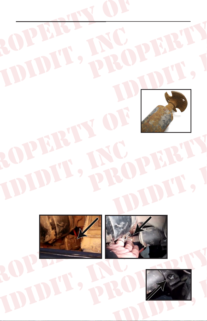
1974-75 Rag Joint Removal:
In the Engine compartment, disconnect the
lower half of the rag joint from the upper half
of the rag joint. This can be done by removing
the two nuts that connect the two halves of the
rag joint together. The OE rag joint (Figure 1)
was pressed onto the column making that half
of the rag joint impossible to remove from the
OE column. Note: A NEW 3/4” 36 half rag
joint (Part Number: 3000383400) will need to be used to reinstall
the column. Also, carefully inspect the other half of the rag joint
to ensure that the rubber is still intact. If the rubber needs to be
replaced give us a call, we can supply you with the new pieces.
(Figure 1)
1976-77 Rag Joint Removal:
In the Engine compartment disconnect the rag joint from the steering
column by removing the 12 point bolt and sliding the rag joint
downward. (Figure 2) If this is a Column Shift column also disconnect
column shift linkage shaft from the column shift lever. (Figure 3)
(Figure 2)
(Figure 3)
Remove the rewall bolt on the steering column
clamp. (Figure 4)
1
(Figure 4)
Page 4

(Figure 5)
Disconnect the stock wiring plug halves. (Figure 5)
(Figure 6)
Move to the inside of the vehicle and
remove the 4 bolts that hold the oor
plate to the rewall. (Figure 6)
Remove the 4 screws that hold the
steering column dash cover (Stock is
plastic, the one pictured is aluminum).
(Figure 7)
In the engine compartment remove the
3 bolts that hold the triangular bracket
(bracket is against the rewall under
the Steering Column). (Figure 8)
(Figure 7)
(Figure 8)
Back in the cabin there are two bolts
that hold the column to the dash frame
work. You can get to them from the 2
holes on the bottom of the dash shown
in picture. (Figure 9) Once removed
take the stock column out carefully
and put it on a bench or oor out of the
way for a while.
2
(Figure 9)
Page 5

Installation of ididit Column:
Column Shift Note: Now for the installation of the column shift
model. On the work bench take off the 4 screws that hold the shift
arm on the bottom of the ididit column and remove the shift lever.
Set aside.
Install the sheet metal bracket on the
lower part of the tube. This bracket was
included with the OE column. Make sure
it is installed with the 4 screw holes on
the upper half and verify its position on
the vehicle. Now install the rubber sleeve
onto the tube. (Figure 10) If salvageable
you can use your original, however if it is not you will need to order
a new one. This piece is not included in the kit, however we can
get one to you if its needed. Pull the sleeve to the same distance
as original one from the end of shaft. Verify that the mounting holes
align with the holes in the rewall.
Wiring: Unplug the factory plug wires
and transfer the same color wire from
the new column to the original plug one
wire at a time. (Figure 11) This column
uses a 1976-77 Ford switch that has the
same color wires as the original switch
does. If you don’t have the original plug
we have included a pair of plugs, both
male and female, and the wire ends just in case. If you use the plugs
we supply you with, make sure to match color to color on both sides.
(Figure 10)
(Figure 11)
Carefully install the column back through
the dash. (Figure 12) At this time a
helper would great. Lower the column
through the rewall and install the two
mounting bolts through the bottom of
the dash. Center these two bolts in the
mounting slots, but do not totally tighten
them just yet. Note: The ididit Steering
Columns underdash mounts are slotted
for easy installation.
3
(Figure 12)
Page 6

In the engine bay re-install the triangular
mount with the 3 bolts, single clamp
and bolt assembly. (Figure 13) If this
is a column shift installation, reinstall
the shift lever at the bottom of the new
column with the provided 4 screws.
(Figure 13)
1974-75 Rag Joint Installation:
Install the rag joint half onto the new ididit
column. Tighten the bolt on the rag joint to 42ft
lbs. Once the rag joint has been installed on the
new column, connect the lower half to the OE
rag joint and tighten the bolts securely.
1975-76 Rag Joint Installation:
Insert the rag joint minus the pinch bolt. Slide the joint up until the
pinch bolt aligns with the groove in the splined shaft and tighten it
to 42ft lbs. If you need to you can move the column up or down in
the vehicle. You can do this because these bolts that secure the
column to the dash have not been tightened all the way down yet.
Back inside the cabin, plug the two wire connectors back together.
(Figure 14) Install the upper and lower
dash cover. Note: You may have to
install a washer between the columns
underdash mount and the vehicles
mounting surface. The washer may be
needed to align the column to the dash
cover to reduce the space between the
two dash cover pieces.
(Figure 14)
4
Page 7

Knobs & Levers:
After removing all items from the package,
A.
assemble the knobs onto the levers. The tilt
lever (shorter of the two levers) goes on the
left side of the column in the hole closest to
the dash. The column has a threaded hole
that this lever threads into. (Figure 15A)
B.
The turn signal lever (longer of the two
levers) goes on the left side of the column
in the hole closest to the driver. The column
has a threaded hole that this lever threads
into. (Figure 15B)
Shift Indicators: Due to the many
transmissions used in vehicle applications,
ididit does not include one with this kit.
C-4, C6 or other gearshift indicators are
a separate piece, but an available option
through ididit. The Shift Indicators are
available in Chrome, Black Powder Coated, Brushed or Polished
Aluminum.
(Figure 15 A & B)
Wheel Installation: This column was designed to use a stock Ford
steering wheel. Just slide it on the top shaft and push it down onto
the splines. Use the nut that was supplied with the new column,
place it on top of the columns top shaft. To secure the wheel
tighten the nut to 45 ft lbs of torque. Install the OE horn assembly
to the wheel and use the factory screws to hold it into place.
Reconnect the battery terminals to the battery.
Floor Shift: If installing a oor shift column your installation is now
complete.
Column Shift: If you are installing a column shift column you need
to hook the transmission gear shift rod going from the column to the
transmission back up.
5
Page 8

Thanks to Wild Horses 4x4 in Stockton, California we now have a
direct t installation video. It has two parts where Jim Creel does
a fantastic job showing how to install ididit’s Steering Column in a
Ford Bronco. The video can be seen on youtube.com under
“wildhorses4x4”.
Need Further Assistance?
ididit, inc has been serving the rodding community for over 25 years and
we take pride in our outstanding customer service. If you need further
assistance, feel free to call us at (517)424-0577, Monday-Friday from 8:30
am - 5:30 pm and Saturday 10:00 am - 2 pm EST. You can also email us at
tech@ididitinc.com.
No part of this guide may be reprinted, reproduced or utilized in any form without the express
written permission of ididit, inc.
2011 ididit, inc.
All Rights Reserved
Printed in the USA
ididit, inc.
610 S. Maumee St., Tecumseh, MI 49286
(517) 424-0577 • (517) 424-7293 fax
www.ididitinc.com
 Loading...