

ididit Retrofit Steering Column 1973 Chrysler B-Body User Manual
Retrot Steering Column
Installation Instructions
for 1973 Chrysler B-Body
For Part #’s: 1620870010, 1620870020, 1620870051, 1620879910,
1620879920, 1620879951
www.ididitinc.com
610 S. Maumee St., Tecumseh, MI 49286
PH: (517) 424-0577 FAX: (517) 424-7293
Instruction # 8000000008 REV 01/13
(A)
Images or examples in this booklet may vary from your specic installation.
(B)
(C)
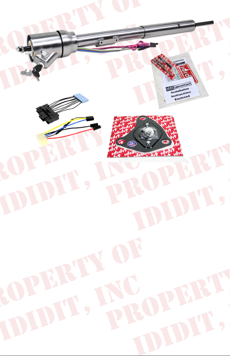
These are the components that come with the column.
(Paintable Steel column pictured above)
(A) Column
(B) Wiring Plugs
(C) Floor Mount
(D) Instructions & Dress Up Kit (Dress Up Kit installed on this column)
We will work through this installation using all the above parts. For
instruction purposes we will assume the vehicle is all original and
uses the OEM harness.
(D)
INDEX
REMOVAL.................................................................... 1 & 2
INSTALLATION OF COLUMN.............................................4
ELECTRICAL INSTRUCTIONS........................................6-7
INSTALLATION OF KNOBS & LEVERS..............................5
WHEEL INSTALLATION......................................................7
No part of this guide may be reprinted, reproduced or utilized in any form without the
express written permission of ididit, inc.
2011 ididit, inc. All Rights Reserved Printed in the USA
Images or examples in this booklet may vary from your specic installation.
REMOVAL of OEM Column: Disconnect positive battery cable.
Before you start your installation, verify that your turn signals, brake
lights, horn & 4-way ashers are working properly. If they all function
now, then they should function properly again once the installation is
complete.
Verify that your steering wheel and driving wheels are straight.
Disconnect the positive terminal on the battery.
While inspecting the components of the kit, take a moment and notice
the output shaft of the new ididit column. We have been the leading
manufacturer of steering columns for a reason. This column can be
used for a Power gearbox, Manual gearbox or a Rack and Pinion
steering system. Note that the lower shaft is a telescoping shaft. If you
grab it and pull, the shaft has enough travel to accommodate all the
different lengths needed. Since these vehicles were also known to
have a lot of ex in the frames, this telescoping feature also increases
the life of the joints in the steering system.
Column Removal
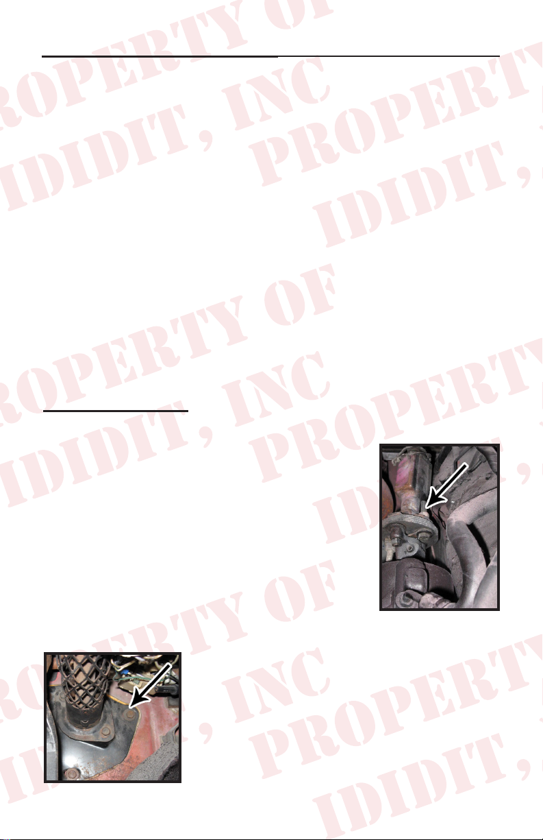
Disconnect the rag joint from your gearbox.
Remove the bolts and nuts that hold the rag joint
together on the box side (1/2 inch wrench). This
allows more room to drive out the roll pin that
goes through the joint end that is attached to the
box. When driving this pin out it is recommended
that you use a 5/16 punch as this will remove the
pin without destroying it. (Figure 1)
Remove the two bolts that lock the rewall
mount to the column ( ½ inch socket with
extension). Remove the three bolts that hold
the rewall mount to the rewall. Next pry (if
necessary) and loosen the large part of the
mount from the rewall. (Figure 2)
(Figure 2)
1
(Figure 1)
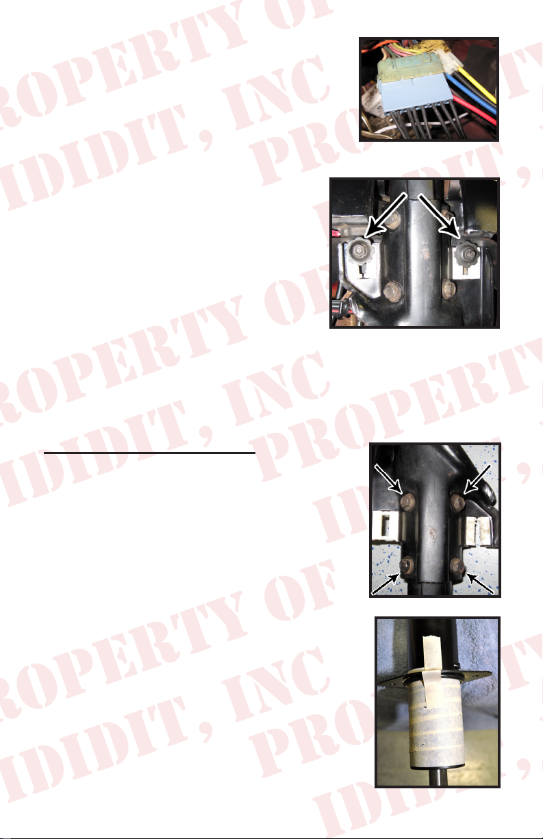
Carefully disconnect both wire plugs from
the column to the dash harness. Take extra
caution, these plugs may be delicate to work
with. (Figure 3)
A helper is great for the next steps.
(Figure 3)
Loosen and remove the three nuts that
hold the column mount under the dash.
Use a 7/16 deep dish socket with a 3 inch
extension to remove the nuts. (Figure 4)
When removing the last nut the weight
of the column will be released. Have
your helper hold the column up while
the last nut is being removed. Now
pull the column out through the inside
(Figure 4)
of the vehicle while the other guides the
column through the pedal area. Guiding will ensure the original
column clears any obstructions that may be in the way (ie. wires,
pedals, etc.).
New Column Preparation
The original under dash mount with the plastic
release blocks will be used on the new column.
If your release blocks are damaged or broken
they need to be replaced either through a
dealer or an online store.
Install the under dash bracket onto the new
column using the provided bolts (5/16-18
with built in lock washers) torque to 22 ft. lbs.
(Figure 5)
Wrap the lower column tube with masking tape
and cover the bottom 4 inches to prevent any
scratches to your new column. (Figure 6)
2
(Figure 5)
(Figure 6)
 Loading...