

Page 1

Retrot Steering Column
Installation Instructions
for 1970-75 Camaro
For Part #’s: 1620860010, 1620860020, 1620860051, 1620869910,
1620869920, 1620869951, 1625860010, 1625860020, 1625860051,
1625869910, 1625869920, 1625869951
www.ididitinc.com
610 S. Maumee St., Tecumseh, MI 49286
PH: (517) 424-0577 FAX: (517) 424-7293
Instruction # 8000000060 REV 04/11
Page 2
Images or examples in this booklet may vary from your specic installation.
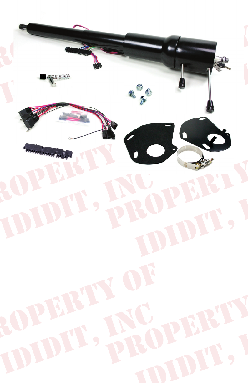
(A)
(C)
These are the components that come with the column.
(Black Powder Coated column pictured above)
(B)
(A) Column & Hardware
(B) Horn Contact Kit
(C) Wiring Plugs with Terminals & Ignition Relay Pack
(D) Floor Mount with Clamp & Gasket
(E) Instructions & Dress Up Kit (Dress Up Kit pictured installed on column)
We will work through this installation using all these parts. For instruction purposes we will assume the car is all original and an OEM
harness.
INDEX
REMOVAL.................................................................... 1 & 2
INSTALLATION OF COLUMN.............................................3
INSTALLATION OF KNOBS & LEVERS..............................4
ELECTRICAL INSTRUCTIONS........................................5-7
WHEEL INSTALLATION......................................................8
NOTES................................................................................9
(D)
Images or examples in this booklet may vary from your specic installation.
Note: These vehicles originally had a Neutral Safety Switch
on the column. Our column does not include one. ididit recommends a neutral safety switch for all automatic transmissions.
If your oor shifter does not have one built in, aftermarket
transmission mounted switches are available.
Page 3

REMOVAL of OEM Column: Disconnect positive battery cable.
Disconnect battery. Verify that your steering
wheel and driving wheels are straight.
Under your hood, locate and remove the bolt
on the coupler between the column and intermediate shaft. Remove the Shift Linkage (if
equipped) from the lower lever on the column.
(Figure 1)
In your car, remove lower valance below column. Note: If equipped with vent controls
this panel can be unscrewed and can hang
off to the side. (Figure 2)
Remove the hard cover from the rewalloor (two screws). (Figure 3)
(Figure 2)
(Figure 1)
Under the dash, there are
2 nuts on the outside of the
dash bracket. Loosen these
two nuts but do not remove.
(Figure 4)
(Figure 4)
(Figure 3)
Remove the 4 bolts that hold the
oor mount to the rewall. Once
the bolts are loose, gently peel/
pry the rewall gasket from the
rewall.
1
Page 4

Removal of Wires:
Half way down the tube on the
steering column, around the
12 O’clock position, there are
three wire plugs to disconnect.
The rst plug is at and about
4 inches long. Pry the release
open and remove the plug.
(Figure 5) There are two more
attached to the ignition switch
that should also be removed.
(Figure 6)
Note: They lock into each other and the
black one must be removed rst. There
are 2 release tabs on this connector.
Then the white or clear connector can
be removed; it has a release tab also.
There are also two plugs on the Neutral
Safety Switch further down the column.
These also must be removed.
(Figure 5)
(Figure 6)
Now the column is ready to be removed.
If possible, have a friend to help you
remove your column because sometimes the joint will stick on the
lower column shaft. If the joint is sticking to the lower shaft, the
joint can be opened with a screwdriver while the column is pulled
from the inside.
Now remove the last two nuts that we had you loosen earlier and
the column will be free. At this point, the column can be pulled
toward the driver and down. Remove the column carefully and
remember that the oor mount is still afxed to the column. Try not
to smack the dash mount on the dash board.
With the column on a work bench you will
need to remove the 4 bolts that hold the
dash mount to the column tube. Note: The
aluminum blocks face the steering wheel
end of the column. We will not be reusing
the bolts. (Figure 7)
2
(Figure 7)
Page 5

Installation of column
Install the original under dash mount to the
column using the provided hardware. Torque
bolts to 22 Ft. Lbs. Now wrap the lower 4-6
inches of the column tube to protect the sur-
face nish of the column when completing
the installation. Next, slide and tape the oor
mount clamp to column. Make sure the clamp
is up and out of the way. (Figure 8)
Since the rewall mount is welded to the
OEM column, we have included a new oor
mount and gasket for this application. Install
the new gasket and mount onto the rewall
with the original bolts loosely. (Figure 9)
(Figure 9)
Slide the new column through the rewall mount and into the intermediate
shaft joint. A helper is highly recommended here to assist with the joint.
Then loosely install the two bolts that
hold the column to the dash. (Figure
10)
(Figure 8)
(Figure 10)
Make sure the gasket is aligned properly and
tighten the oor mount to the oor.
Now tighten the two dash bolts to 42 FT. LBS.
Next tighten the clamp on the oor mount to the
column. This sequence allows the column and
its mounts to secure with no miss-alignment.
(Figure 11)
(Figure 11)
Finally, secure the joint onto the column with the original hardware.
3
Page 6

Knobs & Levers:
Tilt Lever:
After removing all items from the package, screw the
knobs onto the levers. The tilt lever is installed on the left side of
the column in the threaded hole located closest to the dash. We
recommend using Locktite.
Emergency Flasher: The Emergency asher is threaded into the
hole located on the right side of the column. You will noticed the
plastic portion that the asher screws into is ush with the outer
surface when the ashers are in the off position. It is easy to
accidently turn the ashers ON while installing which could lead to
problems later. Check to make sure the ashers are in the OFF
position before continuing.
Turn Signal Lever: A screw is provided with the Dress-up kit. This
screw with secure the turn signal lever to the column. PLEASE
NOTE there are two holes on the turn signal switch. One D shaped
and the other is round. The screw is to be inserted in the round
hole! Use a #2 Phillips screw driver to tighten this screw tightly. It
holds the lever and the switch half’s together. (See Figure 12, 13,
14)
(Figure 12) (Figure 13)
(Figure 14)
4
Page 7

Electrical:
The electrical portion of this is explained in the packet with the
relays that you received with the column.
Note: There may be a dark green wire left over when this
installation is complete. This wire is for the idiot light bulb. If this
is important to you, you can wire this green wire to a 2 wire toggle
switch. Then run an additional wire to a ground and connect to the
other terminal. This will make your idiot lights come on with the
switch so you can check for a bad bulb.
After the relays and wiring are set up and ready, secure the relays
up and out of the way. The relays have mounting tabs to secure
them. They do not need to be grounded individually. They should
be mounted and routed as not to interfere with the pedals or your
feet. It is not recommended to attach these relays to the heater box
as excessive heat will shorten the life of the relays. We found a
nice location up and to the left of the column on a structural gusset
for the rewall. Make sure the black ground wire is connected to a
bare metal surface for a good ground.
NOTE:
It is necessary to secure the relays with the wires
pointing down! They are not waterproof and we do not want
them to collect water for any reason!
NOTE: THE RELAYS AND WIRING RELATED TO THESE
ITEMS ARE NOT FUSED! THEY RECEIVE FULL BATTERY
POWER AT ALL TIMES. Please proceed with caution.
Before connecting the plugs to the column… Make sure the key is
in the off position (Key only comes out in the off position).
There is a small plug with 4 wires coming from the column to the
relay pack, this is the ignition switch plug. This plug has a clasp
on it. We recommend that at rst this plug is only lightly connected
without clicking it together completely. If there are any wiring
issues this is where they will become evident. The red wire will
be where this shows up. If this red wire gets hot… disconnect the
plug and verify that all wires are connected properly.
5
Page 8

If you have purchased this column as a Keyless Ignition
Column please refer to the Touch-N-Go Start keyless
ignition Instructions.
Electrical
Ignition Switch Testing:
1. Verify the vehicle is in park or out of gear if manual transmission.
Insert your key in the ignition and turnkey counter clockwise to the
Accessory position. Radio, blower motor and dome lights should
function.
2. Rotate key clockwise two positions. All accessories should have
power and the ignition system should be on. (Coil or electronic
ignition has power)
3. Rotate key clockwise one more position and the vehicle should
crank and start. If the vehicle does not crank check the neutral
safety switch and verify its function.
If all the functions are correct secure 4 wire ignition connector
tightly.
Simple reference of electrical system:
Red wire Power (in)
Brown wire Accessory feed (out)
Pink wire Ignition feed (out)
Purple wire Starter signal (out)
(cont.)
:
Note: The Purple wire is interrupted with a Neutral Safety
Switch. This car originally had a Neutral Safety Switch
on the column. Our column does not include one. ididit
recommends a neutral safety switch for all automatic
transmissions. If your oor shifter does not have one
built in, aftermarket transmission mounted switches
are available.
6
Page 9

Electrical
(cont.)
:
Turn signal connections:
1970-74 cars will use the
installed 3 7/8 inch wide wire
plug. (Figure 16) Just plug the
two connectors together. They
should match color for color.
1975 cars will require the
connector to be changed to the
4 ¼ inch connector (Figure 17).
Use a small regular screwdriver
(Figure 15)
or scribe to probe into the open
end of the connector and release the terminals. Then re-install the
terminal in the 4 ¼ inch plug in the same terminal location (note
the terminal locations letter P Thru G).
(Terminal)
4 1/4
(Figure 16)
3 7/8
(Figure 17)
Test the turn signals:
1. Leave key off and push emergency asher in. All 4 corners
and dash indicators should light and ash. (Pull for off)
2. Push brake pedal, brake lights should come on.
3. Turn key to on position.
4. Check both left and right turn signals and indicators.
7
Page 10

Steering Wheel Installation:
The original wheel will bolt on almost like it was on the original column. Torque to 45 ft. lbs. The one thing that is different is the retainer
for the horn pin. Originally this was a snap-in item, now it has a twist
lock. This item is a small black plastic piece in the electrical bag. We
bagged it all by itself so it wouldn’t get lost. It looks like this:
The complete assembly should go in this order:
1.) Retainer is inserted onto aluminum
plunger with locking tab towards
1
plunger/at.
2.) Spring is inserted into steering
column horn cam.
3.) Aluminum plunger & retainer are
2
pushed into horn cam with plunger/at
rst. (Figure 18)
4.) While pushing plunger turn Retainer
so that it locks in groove of horn cam.
(Figure 18)
If you have an aftermarket steering
wheel, you may need a wire to attach
the horn (shown right). We have included it with your column, just in case.
(PART# 9000000400)
The large nut on the column to secure the
wheel should be torqued to 45 ft. lbs and
requires a 7/8” socket.
Retainer
(Figure 18)
Horn Wire
It is wise to either unplug the column or
the horn while installing the contact plate.
The contact plate is beveled and should
be installed with the outside being the low
part and the center sitting up. (Figure 19)
Then install the can and plastic piece so
it ts down into the can. (Figure 20) The
notch in the edge of the can should be at
12 o’clock. These screws should be tight.
Now center your horn button and push
back in place (reconnect horn or column
plug). Test the horn.
8
(Figure 19)
(Figure 20)
Page 11

Need Further Assistance?
ididit, inc has been serving the rodding community for over 25 years and
we take pride in our outstanding customer service. If you need further
assistance, feel free to call us at (517)424-0577, Monday-Friday from 8:30
am - 5:30 pm and Saturday 10:00 am - 2 pm EST. You can also email us at
tech@ididitinc.com
Notes:
9
www.ididitinc.com
Page 12

No part of this guide may be reprinted, reproduced or utilized in any form without the express
written permission of ididit, inc.
2011 ididit, inc.
All Rights Reserved
Printed in the USA
ididit, inc.
610 S. Maumee St., Tecumseh, MI 49286
(517) 424-0577 • (517) 424-7293 fax
www.ididitinc.com
 Loading...