

Page 1

Retrot Steering Column
Installation Instructions
1970-74 Cuda/Challenger
For Part Number’s
1620810010, 1620810020, 1620810051, 1620820010, 1620820020, 1620820051
www.ididitinc.com
610 S. Maumee St., Tecumseh, MI 49286
PH: (517) 424-0577 FAX: (517) 424-7293
Instruction # 8000000005 REV 12/12
Page 2
(A)
(B)
(C)
(D)
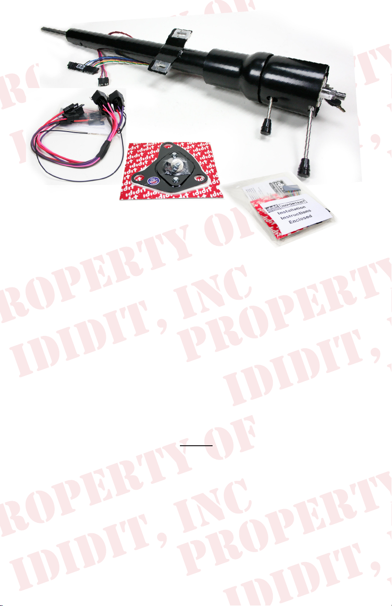
These are the components that should have come with the column.
(Black Powder Coated and Dress-Up kit pictured)
(A) Column
(B) Relay Harness for the Ignition System, Instructions
(C) Floor Mount, Gasket & Hardware
(D) Instructions, Dress Up Kit, Horn Wire & Turn Signal Switch Adaptor
We will work through this installation using all these parts. For instruction purposes
we will assume the car is all original and has a factory manual steering gear box
and an OEM harness. On the last page there will be a summary for optional Equipment, such as a rack and pinion or an aftermarket wiring harness. There will also be
instructions for OEM and aftermarket steering wheels.
INDEX
REMOVAL........................................................................... 2
INSTALLATION...................................................................4
KNOBS & LEVERS..............................................................5
ELECTRICAL....................................................................5-6
TURN SIGNAL WIRING.................................................6-7
STEERING WHEEL..............................................................7
RACK & PINION TECH NOTE..........................................8
AFTERMARKET WIRE HARNESS TECH NOTE..........10
GENERAL ELECTRIC TIPS..............................................10
1
Page 3
REMOVAL of OEM Column:
Disconnect positive battery cable.
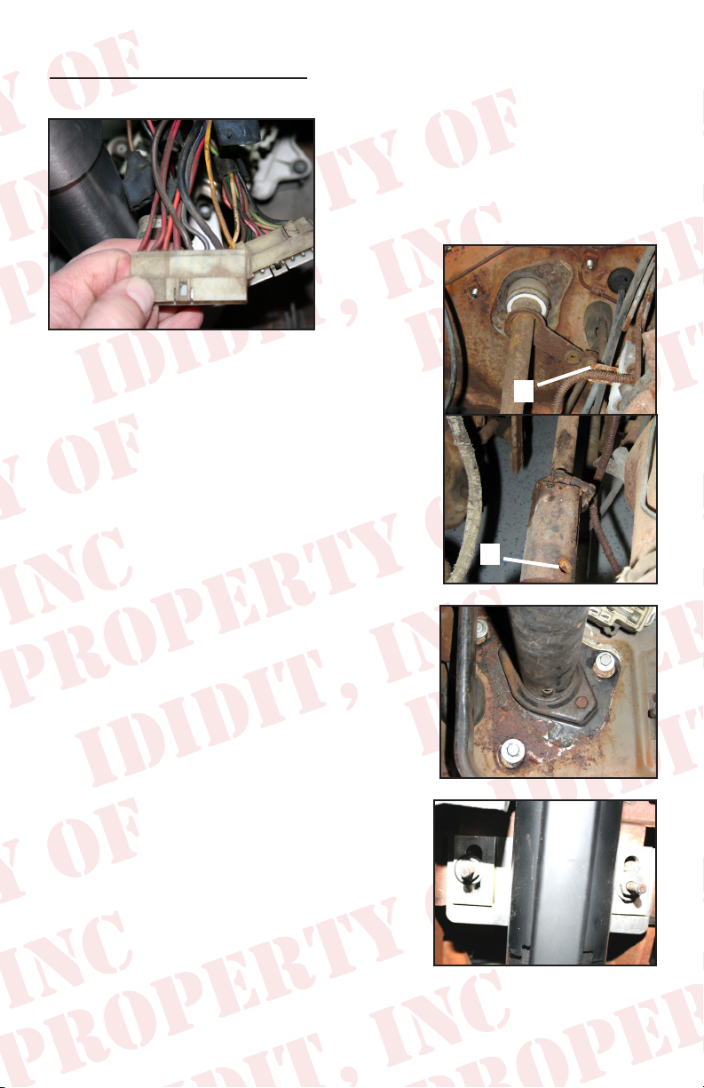
(Figure 1)
Under the dash disconnect two large plugs
from column, to under dash harness. NOTE,
if your car is equipped with a key light, there
may also a single small yellow wire that must
be disconnected. (See Figure 1)
Now you will have to drive out the roll pin in the
coupler on the gear box. We soaked the pin with
penetrating oil and that didn’t help much. I ended
up drilling out the pin with a carbide drill. (drill size5/16 ) (See Figure 2B)
If this car is a 1970 or has column shift, there is a
linkage at the bottom of the column. This linkage
must be disconnected from column. There should
be a cotter pin and a washer. If your vehicle is a
1970 model, and is a oor shift, remove this linkage
completely it will not be reused. (See Figure 2A)
Remove the three bolts that hold the mount to the
re wall, and the two that hold the load plate to
the mount. (See Figure 3)
Now you can remove the two nuts and washers
that hold the column to the dash. Note this will release the column from all mounts and it will want
to fall. After the column is loose you will have to
rotate and watch the re wall mount plate to get
it past the pedals. (See Figure 4)
A.
B.
(Figure 2)
(Figure 3)
(Figure 4)
2
Page 4
INSTALLATION:
The rewall mount is rst, loosen and remove the load plate and o-ring. Install rewall gasket and plate loosely with the bolts and washers provided. Install the plate
with the lip facing the engine side of the rewall. (See Figure 6)
Tip…To do a professional job you
may want to put a layer of masking tape
on the steering column from the tabs
down. The next part of the installation
could scuff the nish on the column.
Column Preparation
Slide the load plate onto the column with the raised lip facing the wheel side of the
column. Then slip the O-ring against the load plate. This will hold the load plate out
of the way while sliding the column in. Locate the 2 nuts and washers provided with
the kit for the dash mount. If you haven’t checked this out yet… pull the lower shaft of
the column out about 2 inches, and then push it back rapidly with your hand. This will
make the column at its shortest point, and will give you the most possible clearance
while sliding through the rewall.
Now with one hand in the middle of the column and one at the top, slide the column be-
tween the pedals and threw the hole in the oor
mount. Set the column against the dash mount
studs and center the studs in the slot provided.
Loosely install the washers and nuts onto the
studs. You should note that the studs and the
slots allow for adjustment of the column from
left to right and front to back. Center the column from front to back and adjust left to right
until the column is centered in the plastic dash
housings as close as possible. Then lightly
tighten bolts. (See Figure 7)
(Figure 6)
(Figure 7)
Next slide the load plate of the rewall mount
down the column till it is against the plate. Install the two bolts and washers and tighten to
11 FT. LBS. (See Figure 8)
3
(Figure 8)
Page 5

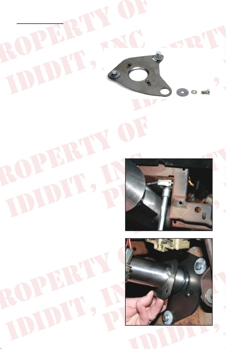
Now move to the engine bay and verify the column is pointing directly at the gearbox. This is
easily accomplished by pulling the shaft out of
the column and up to the tip of the gearbox. If
this is misaligned move the column gently into
place. Once your close, get the U-joint and install it onto the gearbox. Now slide the column
down into the U-joint watching to index it on
the DD shaft properly. (See Figure 9)
If using Rack and pinion, see Tech Section 1
PG 9
With the U-joint installed go back inside the vehicle and center the gasket with the mount and
tighten the three bolts to the re wall (22 FT.
LBS.)
(Figure 9)
Tip.. Please follow the manufactures instructions on the U-joint installation. These
instructions vary by manufacturer. But when all is said and done, ididit recommends
that you use Locktite.
The last item in the column install is to tighten
the dash mount nuts. Verify the column is still
centered from left to right and tighten the two
nuts to 18 FT. LBS. This should be checked
with a torque wrench. (See Figure 10)
(Figure 10)
4
Page 6

Knobs & Levers:
Tilt Lever
After removing all items from the package, screw the knobs onto the levers. The tilt
lever is installed on the left side of the column in the threaded hole located closest to
the dash. We recommend using Locktite.
Emergency Flasher
The Emergency asher is threaded into the hole located on the right side of the
column. You will noticed the plastic portion that the asher screws into is ush with
the outer surface when the ashers are in the off position. It is easy to accidently turn
the ashers ON while installing which could lead to problems later. Check to make
sure the ashers are in the OFF position before continuing.
Turn Signal Lever
A screw is provided with the Dress-up kit. This screw with secure the turn signal
lever to the column. PLEASE NOTE there are two holes on the turn signal switch.
One D shaped and the other is round. The screw is to be inserted in the round hole!
Use a #2 Phillips screw driver to tighten this screw tightly. It holds the lever and the
switch half’s together.
(See Figure 11, 12, 13)
(Figure 11)
(Figure 12)
(Figure 13)
5
Page 7

Electrical:
Please see pack “B” for wiring instructions.
Note: There are up to 3 wires on the ignition plug that may not have a mate. These
wires were for key buzzer and shift indicator. The wiring of the ididit column does
not support these features. The wires are however insulated and should be pro-
tected in the connector.
Testing
Install the key and now we can check the circuits.
One click back counter clock wise and the accessories should come on (radio, heater blower, ect.).
Now turn two clicks forward, this should have the accessories on and the ignition
system on (coil or electronic ignition has power).
OK this is it!! Check that the vehicle isn’t in gear!!! Now go to crank position. (Starter
should engage) and vehicle should start.
6
Page 8

Turn Signal Wiring:
OK This is easy… the bag with the Dress Up Kit also
contains a black wiring plug adaptor. This should
simply plug into the column on the wide plug, and
then the OEM plug from under the dash (See Figure
14) (See Tech Section 2 if you have an Aftermarket
Harness PG 10)
Now you can verify function of the turn signal switch.
(Figure 14)
With the key in an on position check both left and right turn signals.
Then with key in an off position, check Hazard Flashers, in is on, out is off.
Now the brake circuit can be checked by pressing the brake pedal.
Steering Wheel:
This column will accept any of the aftermarket
steering wheels. We offer adaptors for all the
common aftermarket wheels. We also have a
NEW adaptor just for the factory Chrysler wheel.
This adaptor looks like the original can for this
wheel (See Figure 15) but is available in all the
same nishes as the column. This adaptor will put
the wheel back in the OEM location.
(Figure 15)
Otherwise when ordering your wheel tell the person it is an ididit column… if that
doesn’t work… and they give you a stupid look, tell them it’s a 1969-1978 GM passenger car. That should do the trick.
We have provided the nut for the top of the column. This nut should be torqued
to 45 FT. LBS. We have also included the horn wire. This normally will attach to the
center lug of most aftermarket horn buttons.
OEM Wheel with our E body Steering Wheel Adaptor
1. Check to verify the driving wheels are straight. On the top of the column there
is a white tube sticking out of the column. This tube should be between the 10:30
and 11:00 o’ clock position. When the wheels are straight. If this is not true gently
turn the white plastic tube to be in this position. Set the adaptor on the shaft of the
column, this may require you to rotate a little to the closest tooth on the spline.
7
Page 9

2. Install the 9/16 nut and torque to 40 FT. LBS.
3. Install the horn wire by aligning the catch pin and push in, then turn 1/8 of a turn
clockwise. (See Figure 16)
4. Now use the three provided bolts to install the
wheel. (See Figure 17)
(Figure 16)
5. Use the original three screws that held the horn
mechanism in place to re-secure it.
6. Now connect the wire to the electrical tab, and
(Figure 17)
nally push the button over the contact. (See Figure 18)
Aftermarket Replacement Wheels
If using the Grant Tuff Grip aftermarket replacement wheel, with our adaptor. You
will need these additional parts for your horn to work properly. (See Figure 19) We
have a kit that includes all of these components. Kit part number is: 2611010010
If you have any questions about installation you can call our tech line and we will be
happy to walk you through any of the processes. (517)424-0577
(Figure 18)
(Figure 19)
8
Page 10

Rack & Pinion Tech Note:
We installed a UNISTEER kit into the
test car. This column required no
modications. There was no cutting
necessary due to the slip in the lower shaft of the column. It will how ever be necessary to make sure the joint that attaches to the column is a ¾ DD joint.
On a personal note, this rack kit is great. It bolts in, it Fits, and it includes every little
detail that others forget. (Photo 20)
Other rack kits should have similar requirements. The use of the telescoping shaft
on the column should cure any length issues. And the ¾ DD shaft makes attaching
a joint a breeze.
9
Page 11

Aftermarket Wire Harness Tech Note:
There are a few aftermarket harnesses out there for this application. Some are a
direct factory replacement. Others are based on the GM wire color code. Our wire
code is GM based. If you get one of these kits we have matching connectors and
this may also plug directly in. Note that our turn signal plug is the 4 ¼ male plug.
If you have an aftermarket wiring harness, please resist the urge to cut the plug’s
off.
We have both male plugs and both female plugs in stock if you need one that was
not supplied with the kit. These plugs come with terminals, and instructions. If this
is the case for your installation please call us at (517) 424-0577.
General Electrical Tips
Hey it’s a big world… and just in case you are using a unusual combination of parts,
here’s the nuts and bolts of the electrical system.
Turn Signal Switch
Black Horn relay trigger, GROUND TO SOUND
Lt. Blue Left front turn signal and indicator
DK Blue Right front turn signal and indicator
Brown 4 way feed wire, Hot from Flasher Can hot all the time.
Purple Turn signal feed. Hot with ignition on only.
Yellow Left rear turn and brake
Green Right rear turn and brake
White Brake feed from brake switch
Ignition Switch
RED Battery power in by way of back of starter.
Brown Goes to accessory side of fuse panel. Die’s out during crank.
Pink Goes out to coil as feed for ignition, through resistor, and stays hot in
run and crank. Also may be used as feed for limited items on fuse panel such as an
electric fuel pump.
Purple Hot out to starter solenoid. This wire interrupted for Neutral Safety.
Black Ground for the relays to trigger.
10
Page 12

No part of this guide may be reprinted, reproduced or utilized in any
form without the express written permission of ididit, inc.
2009 ididit, inc.
All Rights Reserved
Printed in the USA
ididit, inc.
610 S. Maumee St., Tecumseh, MI 49286
(517) 424-0577 • (517) 424-7293 fax
www.ididitinc.com
 Loading...