

Page 1

Retrot Steering Column
Installation Instructions
for 1967 Mustangs
www.ididitinc.com
610 S. Maumee St., Tecumseh, MI 49286
PH: (517) 424-0577 FAX: (517) 424-7293
Revised 1/22/2014
Instruction #: 8000000014
Page 2
(A)
(B)
(D)
(C)
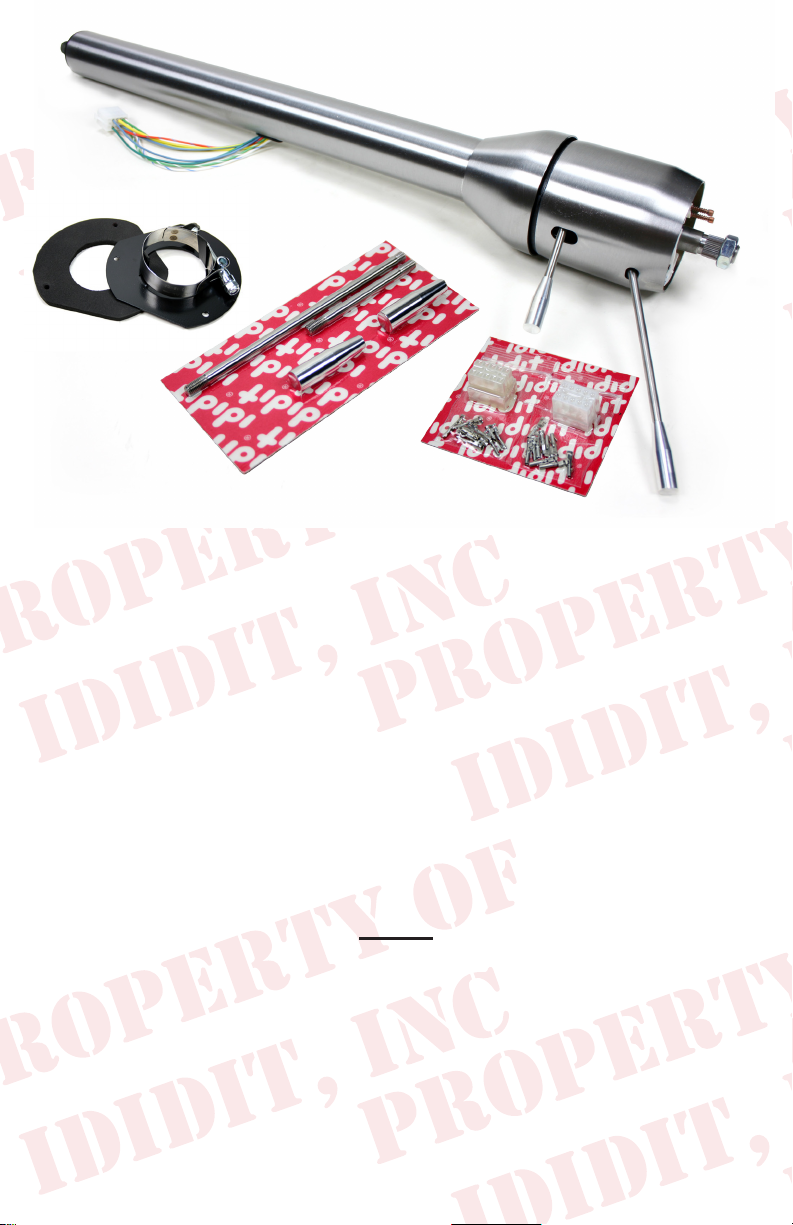
These are the components that come with the column.
(Paintable Steel Column pictured)
(A) Column
(B) Floor Mount Plate with Clamp & Gasket (Part #: 2400010210)
(C) Male & Female Wiring Plugs with Terminals
(D) Instructions & Dress Up Kit (Dress Up Kit pictured with column)
We will work through this installation using all these parts. For instruction
purposes we will assume the car is all original and has a factory manual
steering gear box and an OEM harness. On the last page there will be a
summary for other applications, such as a rack and pinion or aftermarket gear boxes. There will also be instructions for aftermarket steering
wheels.
INDEX
REMOVAL........................................................................ 2
MODIFYING YOUR SHAFT..............................................3
WIRING INSTALLATION............................................4 & 5
COLUMN INSTALLATION..........................................5 & 6
KNOB & LEVER INSTALLATION......................................6
STEERING WHEEL INSTALLATION................................7
1.
Page 3
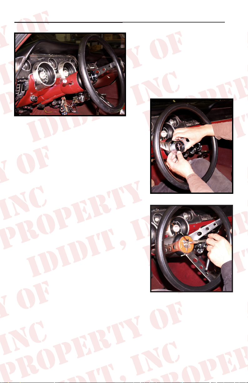
REMOVAL of OEM Column: Disconnect positive battery cable.
To remove the horn button on
your stock steering wheel, push
it in and then rotate counter
clockwise.
Remove the nut and use a wheel
puller to pull the original steering wheel off
the original column.
Now go under the dash and disconnect the
wire plug from the column to the underdash column harness.
Remove the three screws that holds the
gasket to the rewall.
Now you can remove the screws that hold
underdash mount.
You will want to rotate the column left and
right to loosen and then pull the column
back toward the driver to remove it from
the car. There will still be a 3/4” round
shaft sticking into the driver’s side compartment from the gearbox.
(Figure 1)
(Figure 2)
(Figure 2)
2.
Page 4

Measure out 4” from the face of
the nut on the gearbox and cut
shaft.
(Figure 5)
Shaft
4”
The shaft of the gearbox will now
need to be cut into a DD shaft.
Face of Nut
Steering Box
(Figure 5)
This is a round shaft with ats
centered on two sides. An easy way to do this is to make a paper template.
Create your own template by using the measurements from the diagram
below.
Original Shaft
1.000”
New DD Shaft
.395
.945
1.525
2.075
2.356
DD SHAFT
TEMPLATE
Note: Diagram
not to scale
To make 3/4 DD shaft
remove .100” from oppo-
site sides of the shaft
Starting from an 1/8 from the bottom, wrap the paper template around the
shaft and match the horizontal arrows together.
Mark the shaft at the 8 vertical arrow points and draw a line down the length
of the shaft, connecting the marks. This will create the shaded “D” sections
found on the template.
With a grinder or similar tool, grind at the shaded “D” sections to match
the DD shaft. As you work, use the coupler as a guide and test t to ensure
proper tting.
Another option would be to remove the gearbox and take it to your local
machine shop to be modied.
3.
Page 5

Wiring Installation:
The rst few tasks, you can do more easily with the column on a work
bench before you put it in the car!
Wiring
Included in the kit are male and female white plastic connectors and
male & female terminals. The wiring from the switch can be made to t
either this connector OR the original connector. The pins are the same
size as the original.
Using Original Connector: (Easiest!)
Remove the pins from the original
wiring block on the original steering
column and insert the wires on your
new steering column into their proper
location on the original block. *The
color codes should match up. You
will more than likely have to use
a tool to remove the pins from the
plastic connectors. Figure 8 shows two types of tools commonly used.
Using All New Wiring Provided:
Included are male and female blocks along with the necessary terminals
and wiring diagram. You will have to remove the pins from the original
connector off the car side of the harness and insert the pins into the back
side of the new block provided. Insert each terminal completely until
each one snaps into place. You can verify it is secure by lightly tugging
on it. You may need to bend the locking tab back out slightly. Then you
will also install the new block on the column harness. Again, matching
color codes*.
(Figure 8)
*See chart on Page 5
4.
Page 6

Wiring Installation: (Cont.)
Turn Signal Switch**
Orange w/Blue Right rear turn and brake
Green w/Orange Left rear turn and brake
White w/Blue Right front turn signal
Yellow Horn (Power)
Green w/White Left front turn signal
Green Brake feed from brake switch
Blue w/Yellow Horn
Blue Turn signal feed
White w/Red Flasher Feed
*Included with the connector are new terminals for the car side if your originals are not usable or
if you have an aftermarket harness and do not have matching terminals.
**Colors under dash may not match.
Connecting to your Box or Rack:
The ‘67 Mustang will use a 3/4”DDx3/4”36 coupler and depending on
whether you have a Late or Early Mustang will require additional pieces.
The Early ‘67 Mustang (long shaft) will require a 3/4”DDx3/4”36 Coupler.
The Late ‘67 Mustang (short shaft) will require a Coupler (3/4”DDx3/4”36),
Shaft (3/4”DD) and Rag Joint (3/4”36x3/4”DD).
The Early ‘67 Kit Part#: 3000313449 (long shaft steering box)
Kit Includes: 3/4”DDx3/4”36 Coupler, you will also need to modify your
original shaft.
The Late ‘67 Kit Part#: 3006002100 (short shaft steering box)
Kit Includes: 3/4”36x3/4”DD Coupler, 2 5/16” Long DD Shaft,
3/4”DDx3/4”36 Rag Joint.
If you are using a Rack and Pinion set up you will have to design your
own way to hook the column to the rack. We can help with U-Joints and
shafting, but because of headers and different companies making rack
kits we will need more information from you to get the correct installation.
Take the two of the above mentioned kits and install them onto the original steering box per year & kit.
Tip.. Please follow the manufactures instructions on the Coupler & Rag Joint instal-
lation. These instructions vary by manufacturer. But when all is said and done, ididit
recommends that you use Locktite on the threads.
5.
Page 7

Next, slide the oor mount plate, clamp and gasket up the tube of the your
new Mustang column. The nut on the clamp should be on the bottom of
the tube and facing the driver’s side door/fuse box. You can temporarily
hold the mount in place with a piece of masking tape while you install the
column in the car. At this part of the installation an extra set of hands
may be very helpful. With one hand in the middle of the column and one
at the top, slide the column between the pedals and through the hole in
the rewall. Engage the coupler onto the gearbox. Set the column up
into the original dash mount* and loosely install the original bolts into the
original clamp. The tab on the dash mount should be toward the rewall
and engaged into the slot in the bottom side of the tube on the steering
column. Depending on its condition, you may want to replace the rubber
in the dash mount. (We have found that a great substitute is the rubber
from a bicycle inner tube you may have laying around.)
(ididit does have a ‘67 Mustang underdash mount made
for this application if you have misplaced or trashed your
original. That part number is: 2312300010)
Now, if everything is positioned well, you can go back and tighten everything up. Start with the dash mount and tighten original two bolts to 108
– 156 inch lbs*. Next, tighten up the coupler set screw and locking nut to
manufacturer’s specs. Lastly, remove the tape holding the oor mount to
the column. Using the 3 sheet metal screws, secure the oor mount and
gasket to the rewall. Then tighten the oor mount clamp onto the mount
tabs and column to 50 inch lbs*.
*(not foot pounds)
Knobs & Levers:
After removing all items from the package,
assemble the knobs onto the levers. The tilt
lever (shorter of the two levers) goes on the
left side of the column in the hole closest to
the dash. The column has a threaded hole
that this lever threads into. (Figure 9)
The turn signal lever (longer of the two levers)
goes on the left side of the column in the
hole closest to the driver. The column has
a threaded hole that this lever threads into.
(Figure 10)
(Figure 9)
(Figure 10)
6.
Page 8

Steering Wheel:
OEM Wheel - Must be for the same
year application as the column. *Use of
a different year of wheel will result in
damage to the turn signal switch.*
Aim the road wheels so they are pointing straight
ahead. Lower the stock steering wheel onto
the column and center it in its proper position.
Tighten the NEW nut that came with the column
to 45 ft lbs. You may need to adjust the wheel
a bit after driving the vehicle to get the wheel
just where you want it. Re-install the horn and spring by pushing in and
turning clockwise to lock it into place.
Hook the battery back-up and verify that your signals, brake lights, etc
are operating properly. Double check all fasteners including coupler, dash
mount and oor mount to make sure they are all tight.
No part of this guide may be reprinted, reproduced or utilized in any
form without the express written permission of ididit, inc.
2009 ididit, inc.
All Rights Reserved
Printed in the USA
ididit, inc.
610 S. Maumee St., Tecumseh, MI 49286
(517) 424-0577 • (517) 424-7293 fax
www.ididitinc.com
 Loading...