

Page 1

Retrot Steering Column
INSTALLATION INSTRUCTIONS
for 1965 Ford Falcon
FOR PART NUMBER’S: 1170906010, 1170906020,
1170906051, 1130906010, 1130906020, 1130906051
www.ididitinc.com
610 S. Maumee St., Tecumseh, MI 49286
PH: (517) 424-0577 FAX: (517) 424-7293
Instruction # 8000000024 REV 4/14
Page 2

(A)
(B)
(D)
(E)
(C)
WARNING: The column shift column is a
full 2 inches longer than the original column!
The ididit 1965 Ford Falcon Steering Column
comes complete with these components:
(A) Column (Paintable Steel column pictured)
(B) Floor Mount & Hardware
(C) Wiring Connector
(D) Instructions & Dress Up Kit
(E) Gearbox Cover
We will work through this installation using all these parts. For instruction
purposes we will assume the vehicle is all original and has a factory manual
steering gear box and an OEM harness.
Please Note:
A 3/4”-36 x 3/4”DD Coupler (part # 3000313449) is required for installation.
INDEX
OEM COLUMN REMOVAL ................................................... 1-3
ELECTRICAL INSTRUCTIONS ...............................................4
INSTALLATION OF COLUMN .............................................. 5-6
INSTALLATION OF KNOBS & LEVERS ..................................7
STEERING WHEEL INSTALLATION .......................................7
COLUMN SHIFT LINKAGE INSTALLATION ............................8
Page 3
OEM COLUMN REMOVAL:
Verify that your steering wheel and driving wheels are straight.
Disconnect positive battery cable.
To remove the horn button on your stock steering wheel, push it in, then rotate
counter clockwise. Remove the steering wheel nut on the top of the column
and use a wheel puller to pull the original steering wheel off the column.
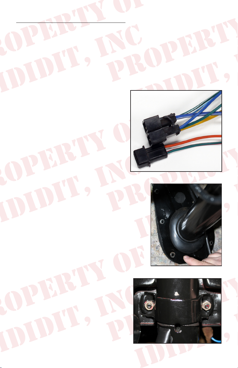
Below the dash mount you should see
two bundles of wire coming out of the
column and going to the dash harness.
There are 2 wires that are grouped
together and also a group of 6, each
with a connector on the end. (Figure
1) Gently disconnect these connectors.
The connectors are very fragile and may
break. (We have provided replacements
just in case.) Once disconnected, tape
these wires to the column to keep them
out of the way.
Figure 1
If you are removing a column shift column,
remove the linkage under the hood for the lower
shift lever.
Back inside the car, remove the six screws
holding the oor mount and gasket in place.
(Figure 2) It may be necessary to pry or scrape
the gasket to remove it from the re wall. We
included a new one with your column, so don’t
panic if the old one gets damaged.
Located just behind the edge of the dash
is the dash mount, carefully remove the
2 bolts that hold the column to the dash.
(Figure 3) NOTE when these bolts are
removed the column will be free from the
dash and may drop a little so watch your
head!
1
Figure 2
Figure 3
Page 4
The outer column, (Mast jacket) should now be loose. Gingerly wiggle
and pull the outer cover of the column from the shaft. There will be years
of dust, grease and maybe some rust holding it in place.
If this is a column shift you will need to rotate the column so the lower
lever does not catch on the rewall.
REMOVAL OF THE GEARBOX
The rst step is to remove the pitman arm. Using the specialized puller
makes this step a breeze.
If you have a vehicle lift and no headers you can just remove the bolts from
the box to the frame and drop the gearbox out the bottom.
If you have headers or no way to lift
a vehicle 4 ft you will have limited
access and will be required to cut
the shaft off rst and then drop the
smaller package thru to the ground.
To do this it is recommended that you
remove the bolts that hold the box to
the frame rail and the 2 lower bolts
for the idler arm. Then have a buddy
push the box up to the re wall as
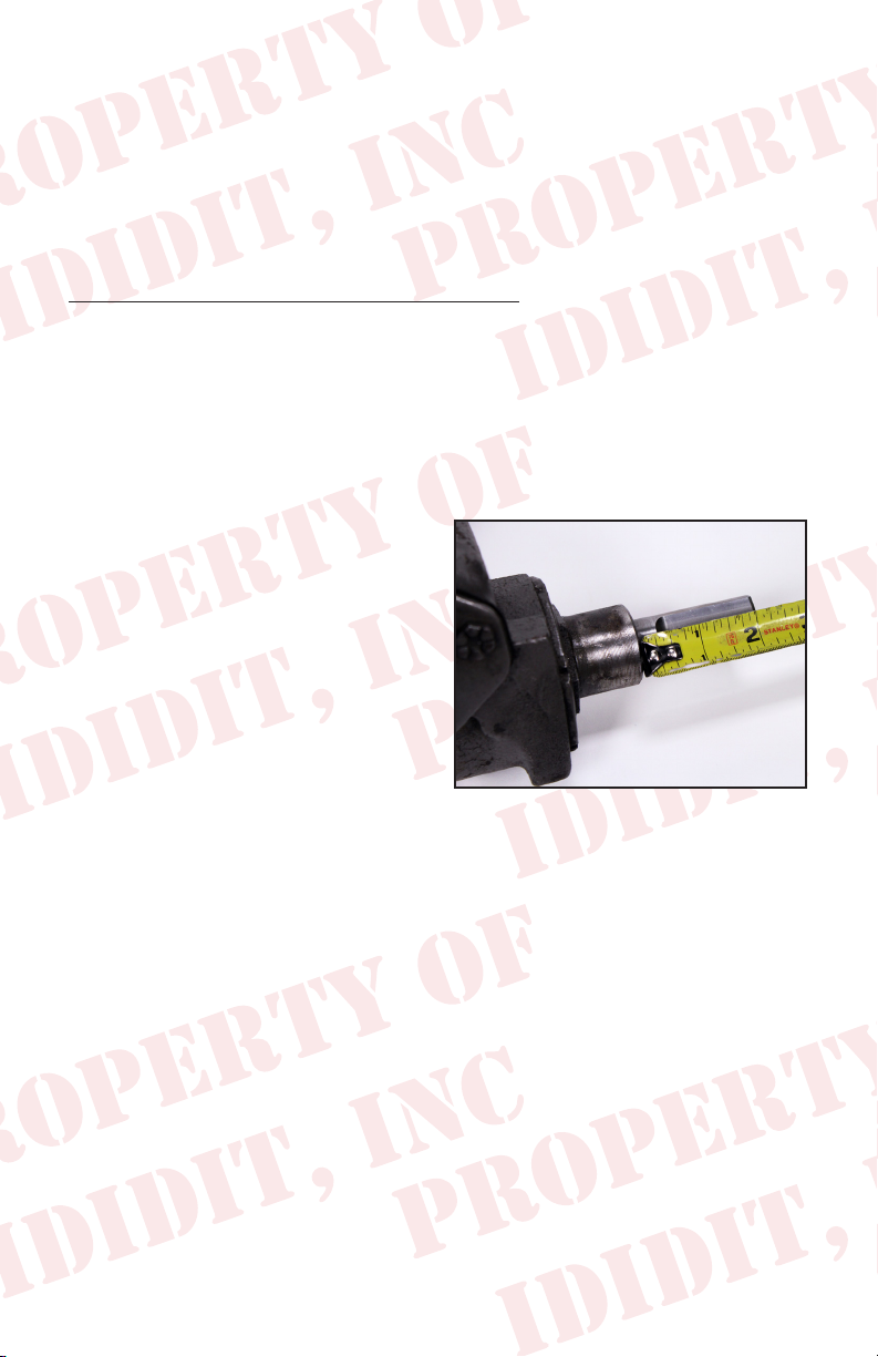
close as possible. Using a Sawsall or a
cutoff wheel, cut the shaft off the box making sure to leave at least 2 inches
of shaft out past the cast shoulder on the box. (Figure 4)
Figure 4
Now that the shaft is shorter you should be able to wiggle the box out.
Once the steering box is out, you should be able to measure 2” from the
cast shoulder on the box and cut the shaft off cleanly. (Figure 4)
The shaft of the gearbox will now need to be cut into a DD shaft. This
is a round shaft with ats centered on two sides. An easy way to do this
is to make a paper template. Create your own template by using the
measurements from the diagram located on the next page.
Starting from an 1/8 from the bottom, wrap the paper template around the
shaft and match the horizontal arrows together.
2
Page 5

1.000”
Original Shaft
New DD Shaft
.395
.945
1.525
2.075
2.356
DD SHAFT
TEMPLATE
Note: Diagram
not to scale
To make 3/4 DD shaft
remove .100” from opposite
sides of the shaft
Mark the shaft at the 8 vertical arrow points and draw a line down the
length of the shaft, connecting the marks. This will create the shaded “D”
sections found on the template.
With a grinder or similar tool, grind at the shaded “D” sections to match
the DD shaft. As you work, use the coupler as a guide and test t to ensure
proper tting. Another option would be to remove the gearbox and take it to your
local machine shop to be modied.
Once the shaft is modied, slip the
gearbox cover on the box and rotate it
so that the set screw is facing down.
Snug the set screw just enough to keep
the cover from spinning. Then slip the
DD end of the coupler onto the gearbox
shaft and tighten the set screws. This
will tell you where to spot drill for the
coupler. We recommend using the point
Figure 5
of a 5/16” drill and drill into the shaft
approximately 3/16” deep. This will
allow you to anchor the set screw to the
shaft. (Figure 5)
Use Locktite and install the coupler’s
set screws and jam nuts onto the
gearbox shaft. (Figure 6)
Figure 6
3
Page 6

WIRING INSTALLATION
We nd the following tasks are much easier to do on a workbench before
installing the column into your car.
New male and female
connectors with terminals
are included with your new
ididit steering column. You
may use these new connectors
with your wiring or you can
use the original connectors.
The terminal pins in the new
connectors are the same size
as the original. If you have an aftermarket harness the new ones may be
helpful for a clean installation. (Figure 7)
If you are using the OEM connectors see the diagram below for the correct
color pin out on your column. (Figure 8)
Figure 7
WIRE SIDE
Steering column plugs
Figure 8
4
Page 7

If you have purchased a shift indicator
for your column shift column this
is the time to install it. Follow the
instructions that were provided, but
please note that there is a large bolt
head that sits dead center on the top
of the column. Also if you install the
turn signal lever and move it to the
neutral position it should be level.
(Figure 9)
INSTALLING YOUR IDIDIT COLUMN
You will need to center the gearbox
travel. To do this, count the turns
while rotating completely from right
to left then rotate back 1/2 as much.
(So if the count was 5 turns then
go back 2 ½ turns) Now reinstall
the gearbox to the frame along with
the idler arm mount. Line up the 4
alignment teeth and re-attach the
pitman arm. (Figure 10)
Figure 9
Figure 10
You will notice on the provided oor
mount that it has a knock out for a clutch.
If you will not be using a clutch DO NOT
use the small triangle piece. The oor
mount and gasket should be installed with
the gasket against the oor steel and the
mount tabs pointing towards the driver
followed by the carpet jute and then carpet.
We recommend not using the rubber trim
piece as it will not work with the clamp
from the mount. (Figure 11) Once the oor
mount is in place, loosely tighten the 6
Figure 11
screws.
To prevent scratching, apply about 4 inches of masking tape around the
bottom of the column then slide the oor mount clamp up the column and
5
Page 8

secure with tape so that it is out of the way.
You will be re-using the original dash
mount so check to make sure the rubber on
the U piece (Figure 12) and the cardboard
backer on the dash to upper mount
surface (Figure 13) are in place & in good
condition. These pieces are important
because the cardboard stops the squeaks
and the rubber adds traction.
(If you are installing a column shift
column, please set the lower shift
lever between the coupler and the
column with the bend facing away
from the end of the column.)
Slide the spline shaft of the column into
the coupler. When properly installed, the
set screw for the coupler should line up
with the groove on the shaft. Remember
to use Locktite on the set screw & jam
nut. You should be able to install the
column and loosely clamp the dash mount
in place. (Figure 14)
Figure 12
Figure 13
The dash mount tab should be facing the
re wall and align with the slot in the
column. Next, slide the oor mount clap
down the column and slide it over the
extensions on the oor mount.
(Figure 15)
If everything is positioned properly, you
can start tightening the mounts, starting
with the dash mount. Tighten the dash
mount to 108-156 inch lbs. Tighten the 6
oor mount screws then secure the clamp
on the 2 tabs and tighten to 50 inch lbs.
While you are under the dash, connect the two wire plugs.
6
Figure 14
Figure 15
Page 9

KNOB & LEVER INSTALLATION
Open packaging and install the knobs
onto the levers. The shorter lever is
the tilt lever, and is threaded into the
hole on the column closest to the dash.
(Figure 16) The longer lever is the turn
signal lever, and is threaded into the
hole closest to the steering wheel. We
recommend using Locktite. (If you have
a column shift, install the shift knob with
the set screw facing the dash.)
Figure 16
STEERING WHEEL INSTALLATION
This column has a Ford top shaft and will accept your stock 1965 Falcon
steering wheel.
Before installing your steering wheel, apply dielectric grease on the horn
pins on the column and on the steering wheel grooves they ride in. When
you put your wheel on, make sure the pins are collapsing straight and not
being bent over.
Aim the road wheels so they are
pointing straight ahead. Lower the
stock steering wheel onto the column
and center it in its proper position.
Tighten the NEW nut that came with
the column to 35 ft lbs. You may
need to adjust the wheel a bit after
driving the vehicle to get the wheel
just where you want it. Re-install the
horn and spring by pushing in and
turning clockwise to lock it into place.
(Figure 17)
Hook the battery back-up and verify that your signals, brake lights, etc
are operating properly. Double check all fasteners including coupler, dash
mount and oor mount to make sure they are all tight.
7
Figure 17
Page 10

COLUMN SHIFT LINKAGE INSTALLATION
Verify that the transmission is in park and then shift the column into park.
Next, compare the rotation of the lower shift lever and the linkage while
matching the lever to the closest matching threaded holes in the column.
Using the provided screws and
washers, install the lower shift lever
into the closest location. (Figure 18)
Shift the column and transmission into
neutral then loosen the adjustment
hardware and loosely install the
linkage while making sure there are no
pinch points where the linkage will rub
on the oor, rewall or the lower shift
lever body. If all looks good, tighten
the hardware and move the column thru
the gears checking for any rubbing,
grinding noises or marks. (Figure 19)
If you nd that the shifter is a little stiff
don’t worry, it will soften a little as
you break it in. If the linkage is very
hard to move however, try loosening
the oor mount just a little. The oor
mount sometimes gets over tightened
which then adds to the required force.
Figure 18
Figure 19
8
Page 11

Need Further Assistance?
ididit, inc has been serving the rodding community for over 25 years and
we take pride in our outstanding customer service. If you need further
assistance, feel free to call us at (517)424-0577, Monday-Friday from 8:30
am - 5:30 pm and Saturday 10:00 am - 2 pm EST. You can also email us at
tech@ididitinc.com
NOTES:
www.ididitinc.com
Page 12

No part of this guide may be reprinted, reproduced or utilized in any
form without the express written permission of ididit, inc.
2014 ididit, inc.
All Rights Reserved
Printed in the USA
ididit, inc.
610 S. Maumee St., Tecumseh, MI 49286
(517) 424-0577 • (517) 424-7293 fax
www.ididitinc.com
 Loading...