

Page 1
Retrot Steering Column
INSTALLATION INSTRUCTIONS
for 1962-66 Nova
FOR PART NUMBER’S: 1120646010, 1120646020, 1120646051,
1070646030, 1070646040, 1140646010, 1140646020,
1140646051, 1150646030, 1150646040
www.ididitinc.com
610 S. Maumee St., Tecumseh, MI 49286
PH: (517) 424-0577 FAX: (517) 424-7293
Instruction # 8000000065 REV 1/14
Page 2

These are the components that come with the column.
(Black Powder Coated column pictured below)
(A)
(B)
(A) Steering column with locating slot
(B) Instructions & Dress up kit (Dress Up Kit pictured with above column)
These components can be purchased separately
depending on your specic installation:
(C)
(D)
(C) Coupler - When used with the OEM gearbox a 3/4-36 X ¾ DD
coupler is necessary (PN: 3000313449).
(D) Floor Mount - ididit recommends our Made to Fit Nova Floor
Mount (PN: 2400020010) that will secure the lower end of your
column to the rewall. See pg 5 & 6 for the specics.
(E) 4-Way Flasher Kit - This 4-way Flasher Kit will connect directly
between the OEM dash harness and the new ididit column. These
kits are broken into 3 year groups 1962 (PN: 3100037616), 1963-65
(PN: 3100037618) and 1966 (PN: 3100037542).
(E)
Images or examples in this booklet
may vary from your specic installation.
Page 3

We will work through this installation using all these parts. For
instruction purposes we will assume the car is all original and that the
dash has not been modied.
INDEX
REMOVAL.................................................................... 1 & 2
INSTALLATION OF COLUMN.............................................3
INSTALLATION OF KNOBS & LEVERS..............................4
ELECTRICAL INSTRUCTIONS........................................5-7
WHEEL INSTALLATION......................................................8
NOTES................................................................................9
REMOVAL of OEM column and gearbox:
Disconnect battery.
Unplug the OEM wire plug from the column and if your vehicle is
equipped unplug the neutral safety switch as well.
Align driving wheels straight ahead. If column shift, block tires to
prevent car from rolling.
Remove your steering wheel.
Loosen and remove the bolts holding the column seal at the rewall.
Pry, scrape or dislodge the seal from the oor.
Carefully remove the nuts that hold the column to the dash.
Note: That the alignment tab is facing the rear of the car.
If equipped, remove the shift linkage from the column in the engine
bay.
At the very end of the column there is a clamp that holds the tube
of the column to the gearbox. This clamp must also be loosened/
removed.
The outer jacket of the tube can now be pulled from the dash. Please
use caution when moving the tube. If this is a column shift application
remove the oor seal from the tube before you get the tube up to the
1
Page 4
dash area. The tube will completely come off the shaft from the
inside of the vehicle. You may have to rotate the tube to clear the
rewall if column shift.
Gear box removal:
If switching to Rack & Pinion System:
Raise the front of the car with jack stands. Jack the car up about 1
foot; unbolt and remove the pitman arm. Unbolt the gearbox from
the frame. Unbolt the driver’s side motor mount from the frame
and jack the motor up just enough to slide the gearbox out. Once
the gearbox is removed the motor mount can be re-attached. (If
already using a Rack & Pinion system move on to pg 5)
If keeping the Stock Box:
Measure down from the dash mount locating tab and mark the
shaft at 21.5 inches. Then raise the front of the car on jack
stands about 1 foot. Un-bolt the pitman arm from the gearbox
and remove it. Unbolt the gearbox from the frame. You will have
to support the motor and unbolt the driver’s side motor mount
from the frame. Jack the motor just high enough to remove the
box. Once the box is removed the motor mount can then be
re-attached.
Gear box modications:
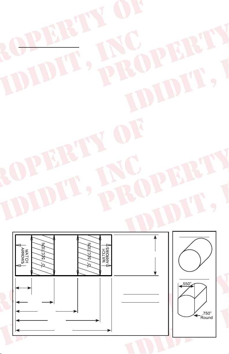
The shaft of the gear box must now be cut to length and modied
to accept the DD Coupler. This is a round shaft with ats centered
on two sides. An easy way to do this is to make a paper template.
Original Shaft
1.000”
New DD Shaft
.395
.945
1.525
2.075
2.356
DD SHAFT
TEMPLATE
Note: Diagram
not to scale
2
2
To make 3/4 DD shaft
remove .100” from opposite
sides of the shaft
Page 5

Create your own by using the measurements from the diagram
shown on the previous page.
Starting from an 1/8 from the bottom, wrap the paper template
around the shaft and match the horizontal arrows together.
Mark the shaft at the 8 vertical arrow points and draw a line down
the length of the shaft, connecting the marks. This will create the
shaded “D” sections found on the template.
With a grinder or similar tool, grind at the shaded “D” sections to
match the DD shaft. As you work, use the coupler as a guide and
test t to ensure proper tting.
Another option would be to remove the gearbox and take it to your
local machine shop to be modied.
Once the shaft is modied slide the
coupler onto the shaft. Mark and
drill the shaft so that it has a dimple
for the set screw. We recommend a
5/16 drill, just deep enough to sink
the point of the drill bit. (Figure 1)
This will allow you to anchor the set
screw to the shaft. Use locktite to
secure the setscrew and jam nut
(Figure 1)
from the coupler to the shaft.
Now you can install the gearbox back on the frame.
Note: The gearbox was probably turned during this process and
needs to be re-centered. Do this by turning the gearbox all the way
in one direction and then count the turns in the opposite direction
until the box stops. For example: Let’s say the count was 4.5…
divide that by 2. In this case bring the box back 2 ¼ turns and it is
centered.
Now the pitman arm can be re-attached and tightened. Once that
is completed the car can be set back down on its tires. Verify the
wheels are still pointed straight ahead.
3
Page 6

Installing the column:
You will be using the original mounts, but you may want to consider
replacing the oor seal. Normally it will be pretty trashed from
removing it the rst time.
Protect that new column!!! We recommend that you wrap the lower
4-6 inches of the column with masking tape. Then slip the seal & oor
mount (with tabs facing engine compartment) over the column. Tape
the seal & mount to the column so it doesn’t scratch the column.
A helper would be handy at this time!
You are going to loosely install the column to mark the setscrew
location.
Install the steering column by sliding
it gently through the rewall and into
the coupler. (Figure 2) You may have
to turn the shaft slightly to engage the
spline into the coupler. While your
supporting the column verify that the
column aligns with the tab in the upper
half of the dash mount. The column
should be inserted into the coupler 1
(Figure 2)
inch.
While holding the column have your helper install the setscrews
into the coupler. Next gently tighten them onto the column & then
loosen and remove the setscrews. Doing this will mark the spot
where you need to drill the shaft! Now remove the column out of the
vehicle and spot drill a dimple into the shaft with the same 5/16 drill
bit approximately 1/8 of an inch deep. This should be just past the
bottom of the spline depth.
You will want to clean and debur this area fully, we recommend using
a small le.
Now have the helper go back outside the re wall and guide the
column into the coupler. Install the setscrew and jam nut with Locktite.
Make sure the setscrew aligns with the dimple on the column.
4
Page 7

Once the column is in place install
the upper and lower halves of the
dash mount loosely. (Figure 3)
Rack and pinion Installation:
Slide the gasket & oor mount
down the column tube with the
prongs of the oor mount facing
towards the engine compartment.
Align the oor mounts screw holes
with the original holes in the oor.
Align the gasket and install the 4
screws with the large washers.
Make sure the dash mount’s
alignment tab is engaged and
secure the mount with its two
fasteners. (Figure 3) Tighten the
two bolts that hold the column to
the dash. Now, from the engine
side install the clamp around the
column and the two tabs and tighten.
(Figure 4)
(Figure 3)
(Figure 4)
For the rack column, the lower interior
rubber trim piece (Figure 5A) will
A
have to be modied as there is no
way to slide the grommet into the
oor mount Figure 5B is the nished
trimmed part ready for installation.
Install the gasket loosely. Put a dab
of silicone or trim adhesive on the
inside where it meets the column to
secure it. You may want to put a piece of
tape around the grommet for 24 hours or
until it dries. Figure 6 shows the trimmed
part properly installed.
5
B
(Figure 5)
(Figure 6)
Page 8

Gearbox Installation:
Slide the seal down the column and align the screw holes for
the seal to the rewall holes. Install the 4 screws with the large
washers.
Make sure the dash mount’s alignment tab is engaged and secure
the dash mount with its two fasteners. (see gure 4 on page 5)
Install the lower trim piece on the column and work it into place.
Synchronizing your Steering Column:
On the top of the steering column there is a white plastic piece with
a male tube sticking up from it. This is called the horn cam. On an
ididit column this should be centered between 10:30 and 11:00
with the front wheels straight. This will make the column cancel
its turn signals with equal turns of the steering wheel. To properly
synchronize your column twist the horn cam until the male tube is
between 10:30 & 11:00. It will have some tension but you can spin
it by hand. Note: Do not try to twist the horn cam with the male
end, grab the complete piece and turn. (Figure 7)
(Figure 7)
6
Page 9

Electrical Connections:
OEM wiring w/Flasher Kit:
If you purchased the optional asher kit;
follow the provided instructions. (Figure 8)
(Figure 8)
The next section has a cross reference chart for the specic years
that this column will work with. (The letters to the left of the ididit
column colors is the letter on the Wire Plug from ididit)
1962 Nova
ididit column Function Car harness
P-White Brake Feed White
N-Green Right rear, turn and brake Purple
M-Yellow Left rear, turn and brake Pink
L-Purple Turn signal asher feed Yellow
K-Brown 4-way asher Feed N/A
J-Dark Blue Right front, turn and indicator Dark Blue
H-Light Blue Left front, turn and Indicator Light Blue
G-Black Horn (ground) Dark Green
1963-65 Nova
ididit column Function Car harness
P-White Brake Feed White
N-Green Right rear, turn and brake Dark Green
M-Yellow Left rear, turn and brake Yellow
L-Purple Turn signal asher feed Purple
K-Brown 4-way asher Feed N/A
J-Dark Blue Right front, turn and indicator Dark Blue
H-Light Blue Left front, turn and Indicator Light Blue
G-Black Horn (ground) Black
7
Page 10

1966 Nova
ididit column Function Car harness
P-White Brake Feed White
N-Green Right rear, turn and brake Dark Green
M-Yellow Left rear, turn and brake Yellow
L-Purple Turn signal asher feed Purple
K-Brown 4-way asher Feed N/A
J-Dark Blue Right front, turn and indicator Dark Blue
H-Light Blue Left front, turn and Indicator Light Blue
G-Black Horn (ground) Black
Aftermarket Harness:
If you have an aftermarket harness use the mate provided in the
kit. Our column has the 3 7/8 inch male GM plug.
OEM wiring w/out Flasher Kit:
If you have the OEM harness and chose
not to get the asher kit… we have a
female connector kit PN# 3106050010.
(Figure 9) This kit includes all the
terminals and the matching connector
to the column.
(Figure 9)
Knobs & Levers:
Tilt Lever:
After removing all items from the package,
screw the knobs onto the levers. The tilt lever
is installed on the left side of the column in
the threaded hole located closest to the dash.
We recommend using Locktite.
(Figure 10)
8
(Figure 10)
Page 11

Turn Signal Lever:
A screw is provided with the Dress-up
kit. This screw will secure the turn signal
lever to the column. PLEASE NOTE
there are two holes on the turn signal
switch. One D shaped and the other
is round. The screw is to be inserted
in the round hole! Use a #2 Phillips
screw driver to tighten this screw tightly.
It holds the lever and the switch half’s
together. (Figure 11)
(Figure 11)
Emergency Flasher Knob:
The Emergency asher is threaded into
the hole located on the right side of the
column. You will noticed the plastic portion
that the asher screws into is ush with the
outer surface when the ashers are in the
off position. It is easy to accidently turn the
ashers ON while installing which could
lead to problems later. Check to make sure
(Figure 12)
the ashers are in the OFF position before continuing.
(Figure 12)
Hook the battery back up & continue with the last steps of
this installation.
OEM wiring w/Flasher Kit:
Test the turn signals:
1. Push brake pedal, brake lights should come on.
2. Push 4-way asher in and verify that the interior indicators and
exterior ashers are ashing properly.
3. Turn key to on position.
4. Check both left and right turn signals and indicators.
9
Page 12

Steering wheels: Torque Steering Wheel Nut to 45ft LBS
Aftermarket Wheels:
This column is designed to accept GM steering wheels from
passenger cars manufactured from 1969 to the late 1980’s (Pre
airbag). Steering wheel Adaptors for most aftermarket wheels are
available through ididit.
OEM Wheels:
Due to the column diameter, OEM
wheels for this car will not match
perfectly. The spline and tapper are
correct but these wheels need an
adaptor ring to match the column
perfectly, and also need a new hole
for the horn wire drilled in the wheel.
This kit (Figure 13) and instructions
are available and it is part # 2612100040
Need Further Assistance?
ididit, inc has been serving the rodding community for over 25 years
and we take pride in our outstanding customer service. If you need
further assistance, feel free to call us at (517)424-0577, MondayFriday from 8:30 am - 5:30 pm and Saturday 10:00 am - 2 pm EST.
You can also email us at tech@ididitinc.com.
(Figure 13)
No part of this guide may be reprinted, reproduced or utilized in
any form without the express written permission of ididit, inc.
2012 ididit, inc.
All Rights Reserved
Printed in the USA
ididit, inc.
610 S. Maumee St., Tecumseh, MI 49286
(517) 424-0577 • (517) 424-7293 fax
www.ididitinc.com
 Loading...