

ididit Retrofit Steering Column 1955-59 Chevy Truck User Manual
Retrot Steering Column
Installation Instructions
Second Series 1955-59 Chevy Trucks
For #’s 1120652010, 1120652020, 1120652051, 1140652010, 1140652020,
1140652051
www.ididitinc.com
610 S. Maumee St., Tecumseh, MI 49286
PH: (517) 424-0577 FAX: (517) 424-7293
Instruction # 8000000003 REV 1/14
(B)
(A)
(E)
(C)
(D)
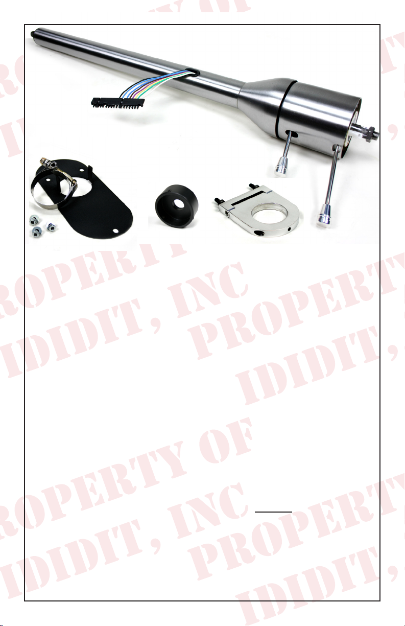
These are the components that come with the column.
(Paintable Steel Column pictured)
(A) Column
(B) Floor Mount
(C) Delrin Cover (for gearbox)
(D) 3.5” Underdash Mount
(E) Instructions & Dress Up Kit (Dress Up Kit pictured with column)
Before Installation Please Read!!!
These installation instructions are based on an original 1955-59 Chevy pickup. If
you have modied the dash, replaced the steering box or have modied the seats
these instruction will change. For instance, a longer or shorter drop may need
to be used if you have modied your seats. The length of the drop will be deter-
mined by the seat height. The column will be put in the stock location by using a
3.5” Underdash Mount and depending on what column you have, the drop hole
diameter will either be 2” (Tilt Floor Shift) or 2” (Tilt Column Shift). If you have
changed over to a rack and pinion system, you may need a U-Joint and additional
shafting. If you are using a power box you will need a Rag Joint. If the dash has
been modied you may need to use a different Underdash Mounting System.
Column Shift Underdash Mounts:
Brushed: 2303370030
Polished: 2303370040
Floor Shift Underdash Mounts:
Brushed: 2303470030
Polished: 2303470040
REMOVAL.................................................................... 1 & 2
UNDERDASH MOUNT & FLOOR MOUNT...........2 & 3
NEW COLUMN INSTALLATION......................................3
WIRING YOUR COLUMN..................................................4
SYNCHRONIZING YOUR COLUMN........................4 & 5
INSTALLATION OF KNOBS & LEVERS..........................6
IMPORTANT INFORMATION...........................................7
INDEX
Pieces NOT included in Kit: Coupler & Wire Harness
(Purchased separately)
Coupler: If you are using the stock box you will also need a 1” DD x 3/4” DD
Coupler (Part #: 3000315249) to join the column to the stock gearbox.
Wiring Harness: If using a stock wire harness you will need a wiring kit for
your truck.
• 1955: 3100035775
• 1956: 3100035780
• 1957-59: 3100035785
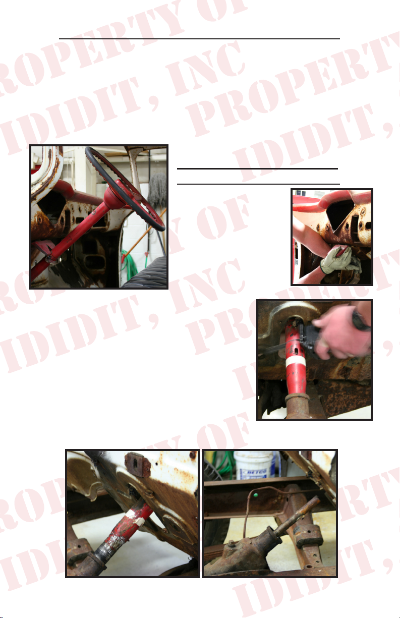
REMOVAL of OEM Column:
Disconnect positive battery cable.
To remove your old col-
umn, disconnect the
wiring that may be connected to the column.
Remove the Floor
Mount and Underdash
Mount that holds the
column in place. Next
cut the column
from the engine bay 5 1/2” up from the gearbox.
Pull what’s left of the original column through the
cab of the truck and eliminate it. The column tube
then needs to be fully removed from the stock
steering box. We recommend unbolting the three
bolts that hold the box and then placing it on a
work bench for easier access. Remove the old
column tube by pulling it out of the steering box.
You may need to use a torch and pipe wrench to
twist the tube out of the original steering box.
1
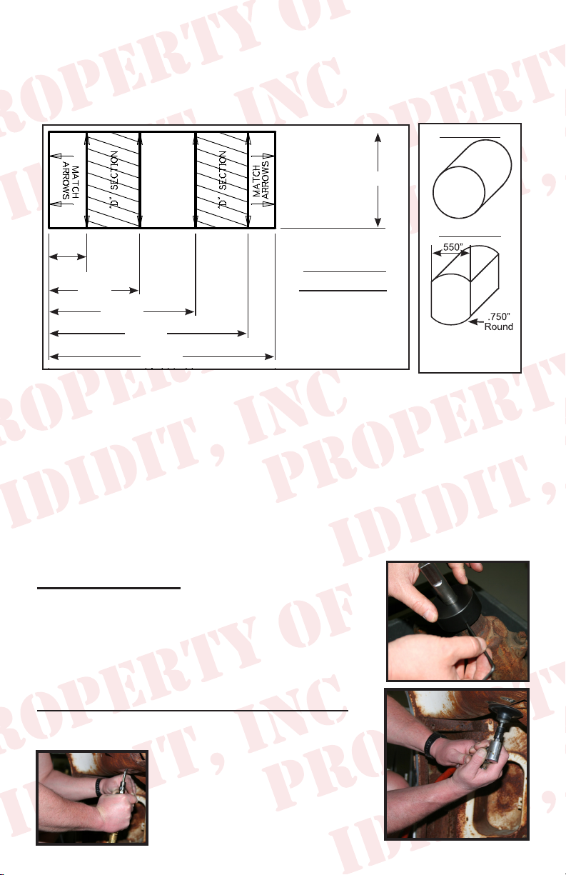
Measure up the shaft from the face of the gearbox 2 1/4” and cut the input
shaft. The shaft of the gearbox will now need to be cut into a DD shaft.
This is a round shaft with ats centered on two sides. An easy way to do
this is to make a paper template. Create your own template by using the
measurements from the diagram below.
Original Shaft
1.000”
New DD Shaft
.395
.945
1.525
2.075
2.356
DD SHAFT
TEMPLATE
Note: Diagram
not to scale
2 1/4”
To make 3/4 DD shaft
remove .100” from opposite
sides of the shaft
Starting from an 1/8 from the bottom, wrap the paper template around the
shaft and match the horizontal arrows together.
Mark the shaft at the 8 vertical arrow points and draw a line down the length
of the shaft, connecting the marks. This will create the shaded “D” sections
found on the template.
With a grinder or similar tool, grind at the shaded “D” sections to match
the DD shaft. As you work, use the coupler as a guide and test t to ensure
proper tting.
Another option would be to remove the gearbox and take it to your local
machine shop to be modied.
Delrin Installation
Slide the provided Delrin seal for the gearbox over the
shaft and push down. Secure the Delrin by screwing
in the 3 set screws. Do not over tighten. Next slide
the coupler onto the shaft of the gearbox and tighten
the Coupler.
Underdash & Floor Mount Installation:
Now that we have the column tube removed and
the box has been modied, the
Underdash Mount has been
removed and the Floor Mount
removed we will then need to
clean and prepare the new dash
and oor mounts.
2
 Loading...