

ididit Golf Cart Steering Column Yamaha User Manual
PROPERTY OF
ididiT, inc
PROPERTY OF
ididiT, inc
PROPERTY OF
ididiT, inc
PROPERTY OF
ididiT, inc
PROPERTY OF
ididiT, inc
PROPERTY OF
Yamaha Golf Cart Instructions
For Part Number’s 1129600020
Yamaha Golf Cart Column Lower Tube
1. Remove the steering wheel from the old column
2. Remove the pitman arm from the steering box (a puller may be necessary)
3. Remove the four bolts that hold the steering box in the cart.
4. Remove the steering box from the cart. Measure carefully. If these
modications are not done correctly the steering column will not t.
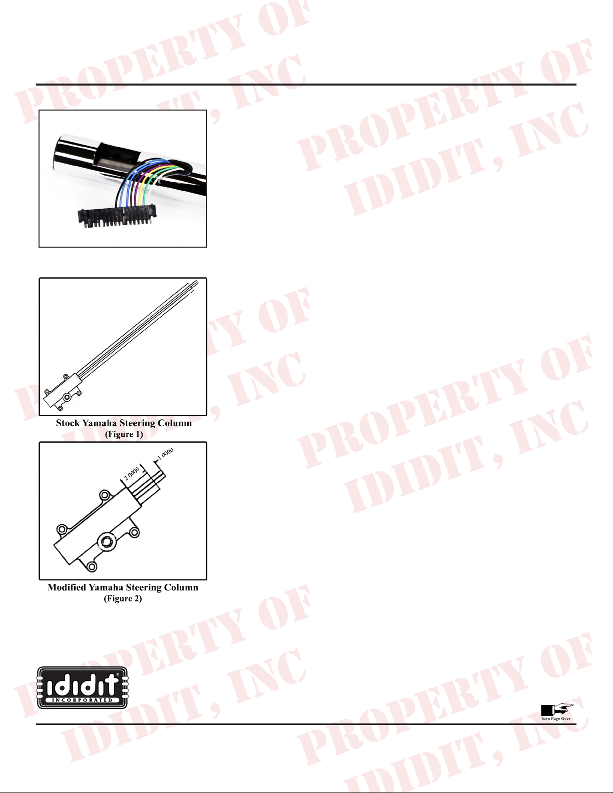
5. Cut the outer housing (black) as shown in the diagram (Figure 1)
a. Cut the outer tube 2” from gearbox housing
b. Cut the outer housing only – DO NOT CUT INNER SHAFT
6. Cut the inner shaft as shown in the diagram (Figure 2)
a. Cut the shaft 3” from gearbox housing
7. Modify the shaft as shown in the diagram (Figure 2)
a. Grind a slot in the shaft ¼” wide x 1/8” deep
b. The centerline of the slot should be ½” from end of shaft and
2 ½” from gearbox housing.
8. Remove the coupler from the lower shaft of the new column.
9. Test t the coupler for clearance. The pinch bolt needs to align with the
slot in the shaft. Place a mark on the coupler and the shaft of the gearbox.
You will use this mark to align the shaft and coupler when installing it in
the cart so make sure it is visible.
10. Reinstall the coupler on the new steering column.
11. Reinstall the modied gearboxes into your cart – do not connect the
pitman arm.
12. Install the 2” long black spacer over the modied tube on the gearbox.
The spacer should t ush against the outer housing of the gearbox.
13. Slide the steering column through opening in the dash.
14. Slide the clamp over the steering column tube.
15. The access hole should be facing towards the ground.
16. Turn the center shaft of the column so the coupler bolts can be seen though
the access hole.
17. Turn the shaft of the gearbox so the slot will line up as a clearance slot for
the pinch bolt. The mark you placed on the shaft should be visible.
18. Align the marks on your coupler and gearbox then carefully slide the
column down over the shaft of the gearbox. The outer housing of the new
column should be ush against the outer housing of the gearbox.
19. Install pinch bolt through the coupler.
20. Pull the t-bolt clamp down approximately ¼” below the access hole and
tighten.
21. Align the gearbox and the steering column. Be sure that the steering
column is centered while the road wheels are pointing forward. The
gearbox must be centered as well. The stock gearbox is 4 ¼” turns lock to
lock you will need to turn the shaft of the box 2 1/8 turns to be at center.
22. Install knobs, levers, wiring, steering wheel adaptor and steering wheel by
(a puller may be necessary)
www.ididitinc.com
ididit inc. 610 S. Maumee St. 49286 Tecumseh, MI PH: 517-424-0577 FAX: 517-424-7293
Instruction #: 8000000054 REV 07/14
PROPERTY OF
ididiT, inc
PROPERTY OF
ididiT, inc
PROPERTY OF
ididiT, inc
PROPERTY OF
ididiT, inc
PROPERTY OF
ididiT, inc
PROPERTY OF
Golf Cart Wiring Instructions
For Part Number’s 1129200120, 1129200020, 1129210020, 1129400020, 1129401020, 1129600020, 1129600120
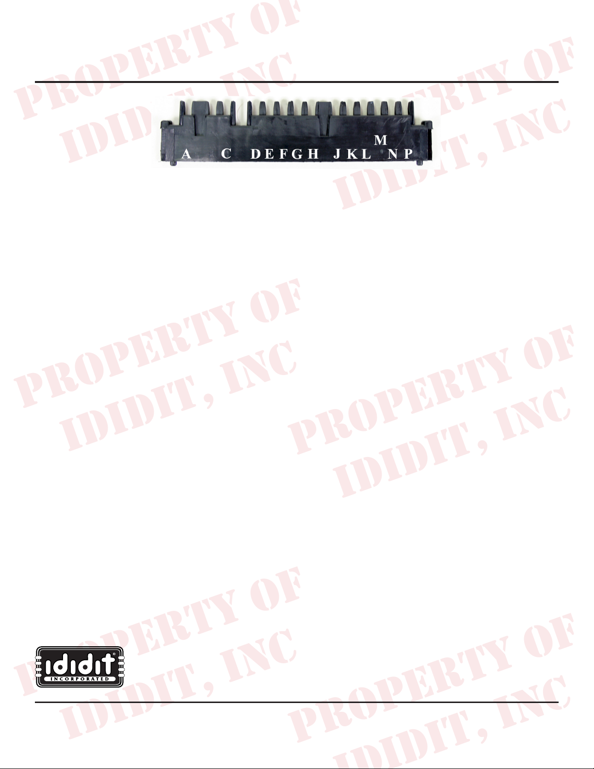
The female side to the male plug on our column has been provided with the column. There are eight crimp-on clips
that will need to be attached to the following wires on your vehicle, then plugged into the corresponding position in the
harness. The female plug is not the exact length of the male plug, however, they will connect properly.
G- Black Wire –Horn Relay (Not Recommended)
Standard GM passenger cars require a horn relay for proper horn function. A horn relay requires three wires, one wire
from a power source, one wire to the horn and a third to the steering column. As the horn button is depressed the column
wire becomes connected to a chassis ground. For this reason, the steering column needs to be connected to that chassis
ground.
The use of a chassis ground in an electric vehicle can be dangerous. If you are using our column in an electric vehicle
the column horn is not recommended without proper technical knowledge and use of relays, fuses, and ground isolation.
H- Light Blue – Left front turn signal light
J- Royal Blue – Right front turn signal light
K- Brown Wire – Emergency asher feed
A wire should come from a constant 12-volt power source through a asher to this wire. When the asher button is
depressed all four lights will light up and ash.
L- Purple - Turn signal feed
A wire should come from a keyed 12-volt power source through a asher to this wire. When the turn signal lever is
depressed the corresponding lights will light up and ash.
Note: The four-way asher and turn signals asher must be two separate ashers.
M- Yellow – Left rear turn signal
N- Green – Right rear turn signal
P- White wire – Brake light feed
A wire should come from a 12-volt power source to the brake switch. The output wire that feeds power to the brake lights
when the brake pedal is depressed should be attached to this white wire. This must be attached through the column to
ensure the proper function of the turn signal while the brakes are applied (turn signals overrides the brake light).
Note: A asher kit is available which contains the asher kit and wiring instructions.
The kit part # is 3100500741.
www.ididitinc.com
ididit inc. 610 S. Maumee St. 49286 Tecumseh, MI PH: 517-424-0577 FAX: 517-424-7293
For Instruction #: 8000000050, 8000000052, 8000000054, REV 12/12
 Loading...