

Page 1
PROPERTY OF
ididiT, inc
PROPERTY OF
ididiT, inc
PROPERTY OF
ididiT, inc
PROPERTY OF
ididiT, inc
PROPERTY OF
ididiT, inc
PROPERTY OF
Neutral Safety Switch Connector Kit
For Part Number’s 9201076280
Parts included in kit:
4-Wire Ends
2-Connectors
Tools necessary for installation:
Wire Stripper/Crimper
Needle Nose Pliers
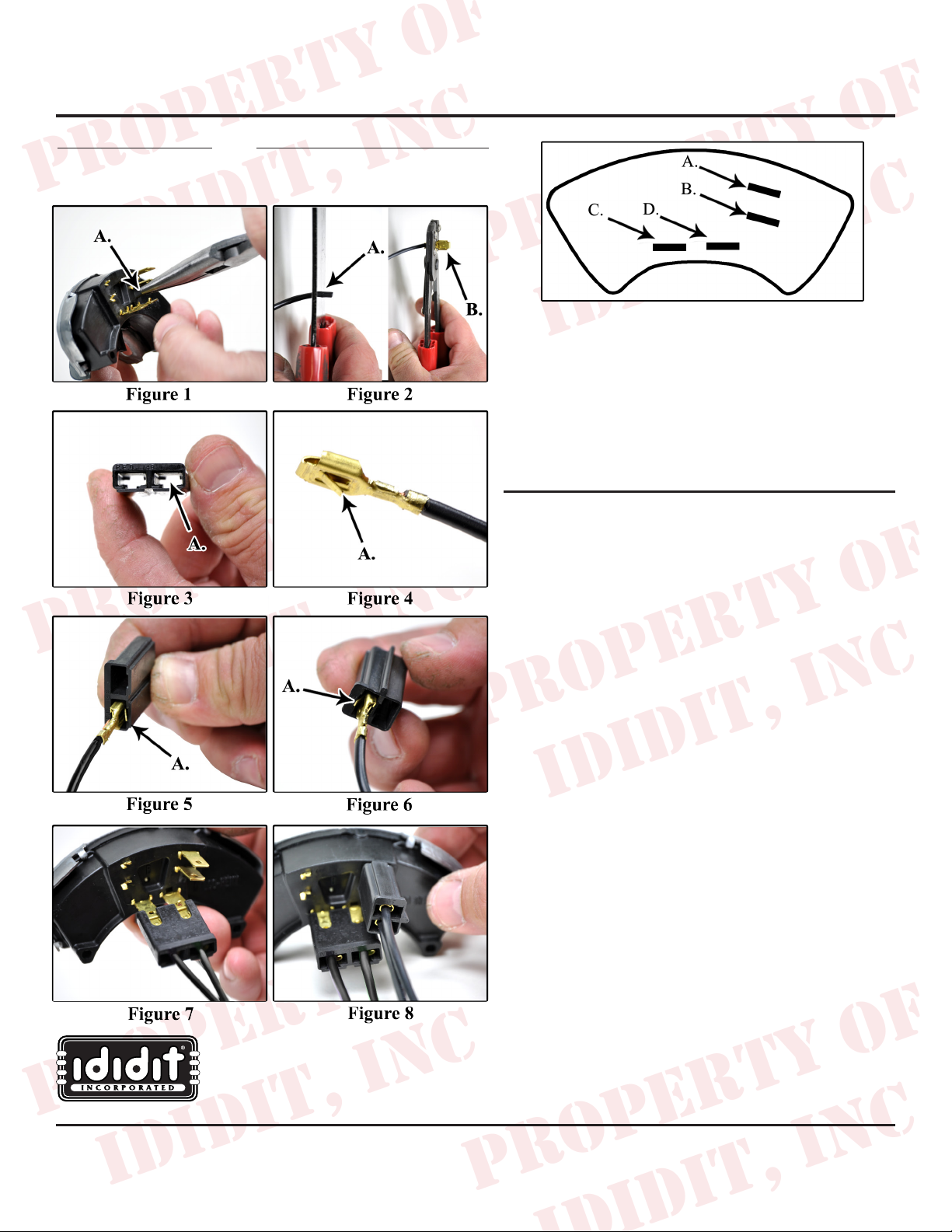
A. Wire goes to the solenoid side of the ignition switch marked
with an “S”.
B. Wire goes to the starter solenoid marked with an “S”
C. Wire goes to the fuse panel to a fuse that is hot all of the time.
D. Wire goes to the back up lights.
Note: A & B can be located to the left rather than the right.
They will function the same.
1. On the Neutral Safety Switch (NSS) you will need to
locate the plastic tab underneath the terminals (Figure
1. A.) on the right hand side of the switch (engine start).
2. With needle nose pliers, snap the plastic tab off. This
will allow access to the terminals without interference.
(Figure 1. A.)
3. Locate wiring for the NSS and backup lights.
4. With a wire stripper, strip 1/4” off the wire (Figure 2.
5. With the wire ends in place, insert them into the
6. Now you can put the connectors on the NSS terminals.
7. Connect the remaining plug (connector) to the
8. Start your engine!
www.ididitinc.com
ididit inc. 610 S. Maumee St. 49286 Tecumseh, MI PH: 517-424-0577 FAX: 517-424-7293
A.) and crimp the wire ends on (Figure 2. B.). Repeat
this step for each of the 4 wires (each wire will have
one wire end).
connector as shown in these gures. Note: Each
connecting point has a slot in it. (Figure 3. A.) Each
wire end has a locking tab on it. (Figure 4. A.) Place
each locking tab in line with the slot in the connector
and push it until it is seated. (Figure 5. & 6. A.)
The right terminal on the backup light, parallel set has a
perforation on it (Figure 7). You will need to connect
the at plug by having the cutouts facing up away from
column.
horizontal terminal set (Figure 8).
Instruction #: 8000020016 REV 01/13
 Loading...