

Page 1
Cable Shift Installation Instructions for:
ididit Column to GM Trans
www.ididitinc.com
ididit Column to 350 Trans.....................................PG1-4
ididit Column to 400 Trans.....................................PG5-8
ididit Column to 700R4 & 4L60 Series Trans.....PG9-12
ididit is...
Your Steering Column Specialist
For #’s
2801000010, 2802000010
ididit inc. 610 S. Maumee St. Tecumseh, MI 49286
PH: 517-424-0577 FAX: 517-424-7293
Instruction # 8000010153 REV 01/13
Page 2
ididit Column to 350 Trans
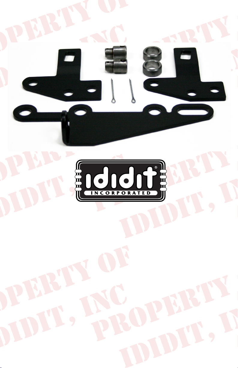
Your kit should contain the following parts:
A.) Transmission Lever
B.) Pan Bracket
C.) Spacers
D.) Cotter Pins
E.) Swivels
F.) Shift Cable
G.) Horseshoe Bracket
H.) Two Piece Bracket
A.
H.
E.
C.
D.
B.
G.
2 Transmission pan bolts are required. They will need to be 1/4”
longer than the stock bolts. You will need to purchase these after
determining whether you need Metric or American.
Before installation please read:
You will need at least 2” of clearance between the rewall and
lower shift lever for this product to function correctly.
Melted Cables: If your cable is too close to your exhaust it will melt or
become brittle. If this is the case you will need to make a heat shield. Do
not wrap the cable as this retains heat. Heat will destroy the cable.
Kinked Cables: Do not kink the cable anywhere along its length. If the
cable has a kink it will lock up. The cable should be kept straight for 2”
on each end where it leaves the bracket. Either of the above could damage
the cable, shifter, and/or transmission in one shift.
1
Page 3
1. Remove the 4 screws from the shift lever at the
bottom of the steering column and set the screws
and the lever safely aside.
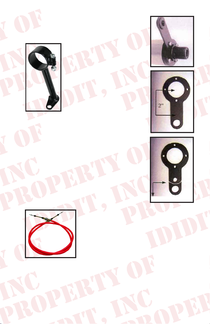
2. Take the cable bracket and
loosen the nut and bolt so that
the clamp will loosen a little.
Put the clamp on the column
with the small end appx. 5
o’clock looking at the column
from the front of the vehicle.
(Actually, anywhere would work
because the clamp is indexable).
The hole on the small end of the
clamp should face the front of
the vehicle. Do not tighten yet.
3. The gearshift lever will need a hole drilled exactly
2” from the center of the large hole towards the
linkage hole, in the center of the shift lever arm.
The hole should be 5/16” or .312 in diameter, no
larger!
4. If your designer eye tells you that you want to cut
off the access of the shift arm that is ne. Take a
look at the diagram to the right to see how we did
this.
Trim if you want to!
5. The cable is the next
piece that you are looking for. Notice that both
ends are the same. We did that so that you could
be right the rst time. You will need to take
the small nut and the rubber boots off so that
you can get one large nut and washer off. Put
the cable through he bracket from the bottom
side of the bracket and reinstall the large nut,
washer and boots. Try to center the nuts and washers on the available
threads. This is important later.
2
Page 4
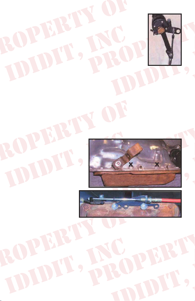
6. Push the cable down through its outer cover so that
it will be as short as possible. Put the column in
Park. Now, gure out where you want the bracket to
be, 5 o’clock will probably be a good place. Install
the swivel on the small thread and turn it until it is
centered on the thread. Now, install the small nut
and turn it until it bottoms out on the swivel. Do not
tighten yet.
7. Reinstall the shift lever as close to the swivel as possible. Now you
could turn the bracket or loosen the large nut and adjust so that the
swivel goes into the 5/16” hole that you drilled in the shift arm. Insert
the cotter pin in the swivel, tighten the large nut and bolt on the bracket.
Do not tighten so much that it squeezes the delrin bushing in the bottom
of the column. This could make it hard to shift. Remember, the cable
has to be pushed down completely.
8. Route the cable towards the rear of the vehicle and then turn it in a
nice U shape. Stay away
from exhaust pipes. If this
cable gets too close, it will
melt and not work at all.
This is very important.
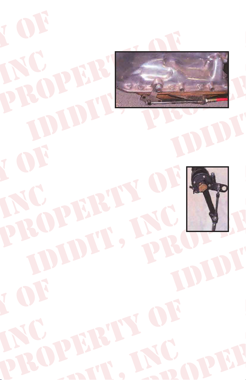
9. Looking at the side of the
transmission, remove the
stock shift lever and the
two pan bolts marked
with X’s. Save the nut
and washer from the
shift lever and the two
pan bolts.
10. The two transmission pan bolts could be either Metric or American
threads. You will need to purchase two bolts 1/4” longer than the two
that you removed. Spacers need to be placed between the bracket and
the transmission pan with the two longer bolts holding it all together in
the holes of the bracket as shown.
3
Page 5
11. Install the transmission shift lever so that the squared end is closest to
the front of the vehicle. Add the washer and the nut to hold it in place.
12. Take the small nut, two
rubber boots, and one
large nut and washer off
the transmission end of
the cable. Insert the cable
into the bracket. Reinstall
the large washer, nut and
two boots. Rotate the shift
lever clockwise to the park
position. Now you are going to put the swivel onto the threaded end
of the cable and turn it until it lines up with the middle hole of the shift
lever. Install the cotter pin. If it needs more travel, loosen the large
nuts and washers and move the cable forward or backward to gain
more travel. Then retighten the large nuts and washers. Install the
small nut and tighten.
13. Try to shift the column. You may experience a
tight pattern, if so slightly loose the bracket around
the column. This should allow the column to move
easier. If not check that the cable is in alignment from
the bracket to the lever.
Cable Adjustment: If you do not adjust the cable correctly you could
damage the cable, shifter and/or transmission. Put the trans in Low gear
and the shifter in Low gear, set the swivel so it slides in and out of the
correct hole freely. Then move the transmission and shifter to Park (all the
way the other way). Rotate the cable swivel until it slips in and out of the
hole freely. Now go back and forth between Park and Low gear and ne
tune the adjustment. See instructions for further detail.
4
Page 6

ididit Column to 400 Trans
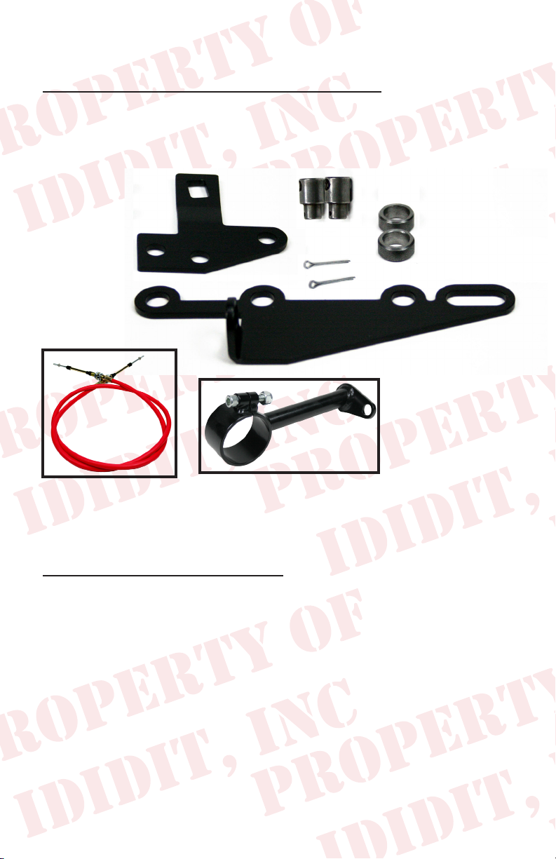
Your kit should contain the following parts:
A.) Transmission Lever
B.) Pan Bracket
C.) Spacers
D.) Cotter Pins
E.) Swivels
F.) Shift Cable
G.) Horseshoe Bracket
H.) Two Piece Bracket
G.
H.
E.
D.
B.
C.
A.
2 Transmission pan bolts are required. They will need to be 1/4”
longer than the stock bolts. You will need to purchase these after
determining whether you need Metric or American.
Before installation please read:
You will need at least 2” of clearance between the rewall and
lower shift lever for this product to function correctly.
Melted Cables: If your cable is too close to your exhaust it will melt or
become brittle. If this is the case you will need to make a heat shield. Do
not wrap the cable as this retains heat. Heat will destroy the cable.
Kinked Cables: Do not kink the cable anywhere along its length. If the
cable has a kink it will lock up. The cable should be kept straight for 2”
on each end where it leaves the bracket. Either of the above could damage
the cable, shifter, and/or transmission in one shift.
5
Page 7

1. Remove the 4 screws from the shift lever at the
bottom of the steering column and set the screws
and the lever safely aside.
2. Take the cable bracket and
loosen the nut and bolt so that
the clamp will loosen a little.
Put the clamp on the column
with the small end appx. 5
o’clock looking at the column
from the front of the vehicle.
(Actually, anywhere would work
because the clamp is indexable).
The hole on the small end of the
clamp should face the front of
the vehicle. Do not tighten yet.
3. The gearshift lever will need a hole drilled exactly
2” from the center of the large hole towards the
linkage hole, in the center of the shift lever arm.
The hole should be 5/16” or .312 in diameter, no
larger!
4. If your designer eye tells you that you want to cut
off the access of the shift arm that is ne. Take a
look at the diagram to the right to see how we did
this.
Trim if you want to!
5. The cable is the next
piece that you are looking for. Notice that both
ends are the same. We did that so that you could
be right the rst time. You will need to take
the small nut and the rubber boots off so that
you can get one large nut and washer off. Put
the cable through he bracket from the bottom
side of the bracket and reinstall the large nut,
washer and boots. Try to center the nuts and washers on the available
threads. This is important later.
6
Page 8

6. Push the cable down through its outer cover so that it will be as short
as possible. Put the column in Park. Now, gure out where you want
the bracket to be, 5 o’clock will probably be a good place. Install the
swivel on the small thread and turn it until it is centered on the thread.
Now, install the small nut and turn it until it bottoms out on the swivel.
Do not tighten yet.
7. Reinstall the shift lever as close to the swivel as
possible. Now you could turn the bracket or loosen
the large nut and adjust so that the swivel goes into
the 5/16” hole that you drilled in the shift arm. Insert
the cotter pin in the swivel, tighten the large nut and
bolt on the bracket. Do not tighten so much that
it squeezes the delrin bushing in the bottom of the
column. This could make it hard to shift. Remember,
the cable has to be pushed down completely.
8. Route the cable towards the rear of the vehicle and then turn it in a nice
U shape. Stay away
from exhaust pipes.
If this cable gets too
close, it will melt and
not work at all. This is
very important.
9. Looking at the side
of the transmission,
remove the stock
shift lever and the
two pan bolts marked
with X’s. Save the
nut and washer from
the shift lever and
the two pan bolts.
10. The two transmission pan bolts could be either Metric or American
threads. You will need to purchase two bolts 1/4” longer than the two
that you removed. Spacers need to be placed between the bracket and
the transmission pan with the two longer bolts holding it all together in
the holes of the bracket as shown.
7
Page 9

11. Install the transmission shift lever so that the squared end is closest to
the front of the vehicle. Add the washer and the nut to hold it in place.
12. Take the small nut,
two rubber boots,
and one large nut
and washer off the
transmission end
of the cable. Insert
the cable into the
bracket. Reinstall
the large washer, nut
and two boots. Rotate the shift lever clockwise to the park position.
Now you are going to put the swivel onto the threaded end of the
cable and turn it until it lines up with the middle hole of the shift lever.
Install the cotter pin. If it needs more travel, loosen the large nuts and
washers and move the cable forward or backward to gain more travel.
Then retighten the large nuts and washers. Install the
small nut and tighten.
13. Try to shift the column. You may experience a
tight pattern, if so slightly loose the bracket around
the column. This should allow the column to move
easier. If not check that the cable is in alignment
from the bracket to the lever.
Cable Adjustment: If you do not adjust the cable correctly you could
damage the cable, shifter and/or transmission. Put the trans in Low gear
and the shifter in Low gear, set the swivel so it slides in and out of the
correct hole freely. Then move the transmission and shifter to Park (all the
way the other way). Rotate the cable swivel until it slips in and out of the
hole freely. Now go back and forth between Park and Low gear and ne
tune the adjustment. See instructions for further detail.
8
Page 10

ididit Column to 700R4 Trans
Your kit should contain the following parts:
A.) Transmission Lever
B.) Pan Bracket
C.) Spacers
D.) Cotter Pins
E.) Swivels
F.) Shift Cable
G.) Horseshoe Bracket
H.) Two Piece Bracket
G.
E.
D.
H.
B.
C.
A.
2 Transmission pan bolts are required. They will need to be 1/4”
longer than the stock bolts. You will need to purchase these after
determining whether you need Metric or American.
Before installation please read:
You will need at least 2” of clearance between the rewall and
lower shift lever for this product to function correctly.
Melted Cables: If your cable is too close to your exhaust it will melt or
become brittle. If this is the case you will need to make a heat shield. Do
not wrap the cable as this retains heat. Heat will destroy the cable.
Kinked Cables: Do not kink the cable anywhere along its length. If the
cable has a kink it will lock up. The cable should be kept straight for 2”
on each end where it leaves the bracket. Either of the above could damage
the cable, shifter, and/or transmission in one shift.
9
Page 11

1. Remove the 4 screws from the shift lever at the
bottom of the steering column and set the screws
and the lever safely aside.
2. Take the cable bracket and
loosen the nut and bolt so that
the clamp will loosen a little.
Put the clamp on the column
with the small end appx. 5
o’clock looking at the column
from the front of the vehicle.
(Actually, anywhere would work
because the clamp is indexable).
The hole on the small end of the
clamp should face the front of
the vehicle. Do not tighten yet.
3. The gearshift lever will need a hole drilled exactly
2” from the center of the large hole towards the
linkage hole, in the center of the shift lever arm.
The hole should be 5/16” or .312 in diameter, no
larger!
4. If your designer eye tells you that you want to cut
off the access of the shift arm that is ne. Take a
look at the diagram to the right to see how we did
this.
Trim if you want to!
5. The cable is the next
piece that you are looking for. Notice that both
ends are the same. We did that so that you could
be right the rst time. You will need to take
the small nut and the rubber boots off so that
you can get one large nut and washer off. Put
the cable through he bracket from the bottom
side of the bracket and reinstall the large nut,
washer and boots. Try to center the nuts and washers on the available
threads. This is important later.
10
Page 12

6. Push the cable down through its outer cover so that it will be as short
as possible. Put the column in Park. Now, gure out where you want
the bracket to be, 5 o’clock will probably be a good place. Install the
swivel on the small thread and turn it until it is centered on the thread.
Now, install the small nut and turn it until it bottoms out on the swivel.
Do not tighten yet.
7. Reinstall the shift lever as close to the swivel as
possible. Now you could turn the bracket or loosen
the large nut and adjust so that the swivel goes into
the 5/16” hole that you drilled in the shift arm. Insert
the cotter pin in the swivel, tighten the large nut and
bolt on the bracket. Do not tighten so much that
it squeezes the delrin bushing in the bottom of the
column. This could make it hard to shift. Remember,
the cable has to be pushed down completely.
8. Route the cable towards the rear of the vehicle and then turn it in a
nice U shape. Stay away
from exhaust pipes. If
this cable gets too close,
it will melt and not
work at all. This is very
important.
9. Looking at the side of the
transmission, remove
the stock shift lever
and the two pan bolts
marked with X’s.
Save the nut and
washer from the shift
lever and the two pan
bolts.
10. The two transmission pan bolts could be either Metric or American
threads. You will need to purchase two bolts 1/4” longer than the two
that you removed. Spacers need to be placed between the bracket and
the transmission pan with the two longer bolts holding it all together in
the holes of the bracket as shown.
11
Page 13

11. Install the transmission shift lever so that the round end is closest to the
front of the vehicle. Add the washer and the nut to hold it in place.
12. Take the small nut, two
rubber boots, and one
large nut and washer off
the transmission end of
the cable. Insert the cable
into the bracket. Reinstall
the large washer, nut and
two boots. Rotate the shift
lever clockwise to the park
position. Now you are going to put the swivel onto the threaded end
of the cable and turn it until it lines up with the forward hole of the
shift lever. Install the cotter pin. If it needs more travel, loosen the
large nuts and washers and move the cable forward or backward to
gain more travel. Then retighten the large nuts and washers. Install
the small nut and tighten.
13. Try to shift the column. You may experience a
tight pattern, if so slightly loose the bracket around
the column. This should allow the column to move
easier. If not check that the cable is in alignment
from the bracket to the lever.
Cable Adjustment: If you do not adjust the cable correctly you could
damage the cable, shifter and/or transmission. Put the trans in Low gear
and the shifter in Low gear, set the swivel so it slides in and out of the
correct hole freely. Then move the transmission and shifter to Park (all the
way the other way). Rotate the cable swivel until it slips in and out of the
hole freely. Now go back and forth between Park and Low gear and ne
tune the adjustment. See instructions for further detail.
12
Page 14

Warnings!!! Please read!!!
You will need at least 2” of clearance between the rewall and lower
shift lever for this product to function correctly.
Melted Cables: If your cable is too close to your exhaust it will melt or
become brittle. If this is the case you will need to make a heat shield. Do
not wrap the cable as this retains heat. Heat will destroy the cable.
Kinked Cables: Do not kink the cable anywhere along its length. If the
cable has a kink it will lock up. The cable should be kept straight for 2” on
each end where it leaves the brass. Either of the above could damage the
cable, shifter, and/or transmission in one shift.
Cable Adjustment: If you do not adjust the cable correctly you could
damage the cable, shifter and/or transmission. Put the trans in Low gear
and the shifter in Low gear, set the swivel so it slides in and out of the correct hole freely. Then move the transmission and shifter to Park (all the
way the other way). Rotate the cable swivel until it slips in and out of the
hole freely. Now go back and forth between Park and Low gear and ne
tune the adjustment. See instructions for further detail.
If you are having problems with your installation
please contact us at:
PH: (517) 424-0577 or email: tech@ididitinc.com
M-F 8:30a-5:30p EST
Sat. 10:00a-2:00p
www.ididitinc.com
13
Page 15

Think you may have forgotten something?
Here’s what you may have missed:
Add Ons: (Add Ons should be installed on the column prior to shipment)
Cruise Control: Carbureted Engine or Fuel Injected Engine?
Dimmer or Wiper: Dimmer/Wiper Kits will replace the original knobs and
levers that come standard on an ididit column. This is a replacement lever with a
push button at the end of the knob. The Dimmer/Wiper kit when pushed is either
On or Off. Includes relay kit.
Accessories:
Steering Wheel: We cannot recommend any brand of wheel because there are
so many to choose from. If you are having a hard time guring out if a wheel you
had purchased will work with an adaptor or an ididit column, simply give us a call.
Steering Wheel Adaptor: Unless using original 1969 & Up Steering Wheel you
will need an adaptor. The adaptor may depend on the wheel. ididit recommends
purchasing the Steering Wheel prior to purchasing the adaptor. 3, 5, 6 or 9-Bolt
Adaptors are Available with nishes of Chrome, Black Powder Coated, Brushed
or Polished Aluminum. The adaptors are available with or without Horn Buttons.
Under dash Mount (A.K.A. Column Drop): A solid under dash mount is very
necessary when installing your steering column. ididit offers several variations of
under dash mounts for Floor Shift & Column Shift Columns. When measuring for
your column drop, measure from the center of the column to the dash (see diagram).
Floor Mount: Like the under dash mount this piece is very necessary when
installing your steering column safely. ididit offers a Classic Floor Mount, Swivel
Ball Floor Mount, Adjustable Floor Mount with or without a trim piece. Available
for any ididit Steering Column.
Shift Indicator: Shift indicators available are 3 or 4-speed transmissions. ididit
also carries shift indicators for Ford AOD & AODE transmissions. The indicators
are acrylic and can be ordered with or without the housing. The housing nishes
include: Chrome, Black Powder Coated, Brushed or Polished Aluminum.
Accessory Knobs for Levers or Dash: Deco or Retro knobs are available to re-
place the standard knobs that come standard on the column or if you plan on matching those knobs to your dash knobs. Deco knobs are only available in Polished Aluminum. Standard and Retro Knobs are available in Chrome, Black Powder Coated,
Brushed or Polished Aluminum.
14
Page 16

No part of this guide may be reprinted, reproduced or utilized in any
form without the express written permission of ididit, inc.
2009 ididit, inc.
All Rights Reserved
Printed in the USA
ididit, inc.
610 S. Maumee St., Tecumseh, MI 49286
(517) 424-0577 • (517) 424-7293 fax
www.ididitinc.com
 Loading...