

VS-606V7 Series
Instruction Manual
COMPACT GENERAL-PURPOSE INVERTER
(VOLTAGE VECT OR CONTROL)

PREFACE
YASKAWA’s VS-606V7 is such a small and simple
inverter; as easy as using a contactor. This
instruction manual describes installation,
maintenance, inspection, troubleshooting, and
specifications of the VS-606V7. Read this instruction
manual thoroughly before operation.
YASKAWA ELECTRIC CORPORATION
General Precautions
• Some drawings in this manual are shown with the protective covers and shields
removed, in order to describe detail with more clarity. Make sure all covers and
shields are replaced before operating this product.
• This manual may be modified when necessary because of improvement to the
product, modification, or changes in specifications.
Such modifications are denoted by a revised manual No.
• To order a copy of this manual, if your copy has been damaged or lost, contact you
YASKAWA representative.
• Y ASKAWA is not responsible for any modification of the product made by the
user, doing so will void the warranty.
2
NOTES FOR SAFE OPERATION
Read this instruction manual thoroughly before installation, operation, maintenance or
inspection of the VS-606V7. In this manual, NOTES FOR SAFE OPERATION are
classified as “WARNING” or “CAUTION”.
WARNING
Indicates a potentially hazardous situation which, if not avoided, could result in death
or serious injury to personnel.
CAUTION
Indicates a potentially hazardous situation which, if not avoided, may result in minor or
moderate injury to personnel and damage to equipment. It may also be used to alert
against unsafe practices.
Even items described in may result in a vital accident in some situations.
In either case, follow these important notes.
These are steps to be taken to ensure proper operation.
NOTE
CAUTION
3
Warnings for UL/cUL Marking
• Do not connect or disconnect wiring, or perform signal checks while the power
supply is turned ON.
• The Inverter internal capacitor is still charged even after the power supply is turned
OFF. To prevent electric shock, disconnect all power before servicing the Inverter.
Then, wait at least one minute after the power supply is disconnected and all
indicators are OFF.
• Do not perform a withstand voltage test on any part of the Inverter. This electronic
equipment uses semiconductors and is vulnerable to high voltage.
• Do not remove the Digital Operator or the blank cover unless the power supply is
turned OFF. Never touch the printed control board (PCB) while the power supply is
turned ON.
The Inverter is not suitable for use on a circuit capable of delivering more than
•
18,000 RMS symmetrical amperes, 250volts maximum (200V class units) or
18,000 RMS symmetrical amperes, 480volts maximum (400V class units).
CAUTION
(Ref. page)
Low voltage wires shall be wired with Class I Wiring.
. . . . . . . . . . . . . . . 22
4
RECEIVING
CAUTION
• Do not install or operate any inverter which is damaged or
has missing parts.
Failure to observe this caution may result in personal injury or
equipment damage . . . . . . . . . . . . . . . . . . . . . . . . . . . . . . . . . . . . . . . . . . . .14-16
MOUNTING
CAUTION
• Lift the cabinet by the cooling fin. When moving the unit, never
lift by the plastic case or the terminal covers.
Otherwise, the main unit may be dropped causing damage to the unit.. . . . . . 18
• Mount the inverter on nonflammable material (i.e., metal).
Failure to observe this caution can result in a fire.. . . . . . . . . . . . . . . . . . . . . . 18
• When mounting units in an enclosure, install a fan or other
cooling device (open chassis to keep the intake air temperature
below 122°F (50°C).
Overheating may cause a fire or damage to the unit. . . . . . . . . . . . . . . . . . . . . 19
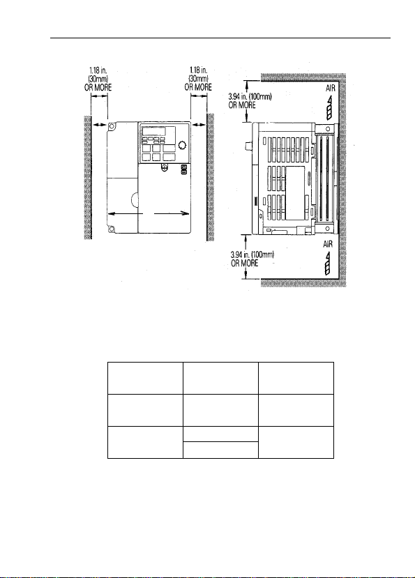
• The VS mini generates heat. For effective cooling, mount it
vertically.
Refer to the figure in “Mounting Dimensions” on page 18.
(Ref. page)
(Ref. page)
5
WIRING
WARNING
(Ref. page)
• Start wiring only after verifying that the power supply
is turned OFF.
Failure to observe this warning can result in electric shock
or fire. . . . . . . . . . . . . . . . . . . . . . . . . . . . . . . . . . . . . . . . . . . . . . . . . . . . . . . . . 22
• Wiring should be performed only by qualified personnel.
Failure to observe this warning can result in electric shock
or fire. . . . . . . . . . . . . . . . . . . . . . . . . . . . . . . . . . . . . . . . . . . . . . . . . . . . . . . . . 22
• When wiring the emergency stop circuit, check the wiring
thoroughly before operation.
Failure to observe this warning can result in personal injury. . . . . . . . . . . . . . 22
WARNING
(Ref. page)
• Make sure to ground the ground terminal according to the local
grounding code.
Failure to observe this warning can result in electric shock
or fire. . . . . . . . . . . . . . . . . . . . . . . . . . . . . . . . . . . . . . . . . . . . . . . . . . . . . . . . . 25
• For 400V class, to conform to CE requirements, make certain to ground the
supply neutral.
Failure to observe this warning can result in electric shock
or fire. . . . . . . . . . . . . . . . . . . . . . . . . . . . . . . . . . . . . . . . . . . . . . . . . . . . . . . . . 25
6

CAUTION
• Verify that the inverter rated voltage coincides with the
AC power supply voltage.
Failure to observe this caution can result in personal injury
or fire.
• Do not perform a withstand voltage test of the inverter
It may cause semi-conductor elements to be damaged.
• To connect a braking resistor, braking resistor unit or braking
unit, follow the procedures described in this manual.
Improper connection may cause a fire.. . . . . . . . . . . . . . . . . . . . . . . . . . . . . . . 25
• Make sure to tighten terminal screws of the main circuit
and the control circuit.
Failure to observe this caution can result in a malfunction,
damage or a fire. . . . . . . . . . . . . . . . . . . . . . . . . . . . . . . . . . . . . . . . . . . . . . . . . 22
• Never connect the AC main circuit power supply to output
terminals U, V and W.
The inverter will be damaged and void the warranty. . . . . . . . . . . . . . . . . . . . 22
• Do not connect or disconnect wires or connectors while
power is applied to the circuit.
Failure to observe this caution can result in personal injury.
• Do not change signals during operation
The machine or the inverter may be damaged.
(Ref. page)
7

OPERATION
WARNING
• Only turn ON the input power supply after replacing the
digital operator/blank cover (optional).
Do not remove the digital operator or the covers while
current is flowing.
Failure to observe this warning can result in electric shock.
• Never operate the digital operator or dip switches when
your hand is wet.
Failure to observe this warning can result in electric shock.
• Never touch the terminals while current is flowing, even
during inverter stopping.
Failure to observe this warning can result in electric shock.
• When the fault retry function is selected, stand clear of
the inverter or the load, since it may restart suddenly
after being stopped.
(Construct machine system, so as to assure safety for personnel,
even if the inverter should restart.) Failure to observe this
warning can result in personal injury.. . . . . . . . . . . . . . . . . . . . . . . . . . . . . . . . 60
• When continuous operation after power recovery is selected,
stand clear of the inverter or the load, since it may restart
suddenly after being stopped.
(Construct machine system, so as to assure safety for personnel,
even if the inverter should restart.) Failure to observe this
warning can result in personal injury.. . . . . . . . . . . . . . . . . . . . . . . . . . . . . . . . 55
• Since the digital operator stop button can be disabled by a
function setting, install a separate emergency stop switch.
Failure to observe this warning can result in personal injury.
• If an alarm is reset with the operation signal ON, the inverter
restarts automatically. Only reset the alarm after verifying that
the operation signal is OFF.
Failure to observe this warning can result in personal injury. . . . . . . . . . . . . . 27
(Ref. page)
8
OPERATION (Cont.)
CAUTION
(Ref. page)
• Never touch the heatsink or braking resistor, the
temperature is very high.
Failure to observe this caution can result in harmful burns
to the body.
• Since it is easy to change operation speed from low to
high speed, verify the safe working range of the motor
and machine before operation.
Failure to observe this caution can result in personal injury
and machine damage.
• Install a holding brake separately if necessary.
Failure to observe this caution can result in personal injury.
• Do not change signals during operation.
The machine or the inverter may be damaged.
• All the parameters of the inverter have been preset at
the factory. Do not change the settings unnecessarily.
The inverter may be damaged. . . . . . . . . . . . . . . . . . . . . . . . . . . . . . . . . . . . . . 28
MAINTENANCE AND INSPECTION
WARNING
(Ref. page)
• Never touch high-voltage terminals in the inverter.
Failure to observe this warning can result in an electrical shock. . . . . . . . . . 127
• Disconnect all power before performing maintenance or
inspection. Then wait at least one minute after the power
supply is disconnected and all LEDs and CHARGE LED
are extinguished.
The capacitors are still charged and can be dangerous. . . . . . . . . . . . . . . . . . 127
9
WARNING
• Do not perform withstand voltage test on any part of
the VS-606V7.
This electronic equipment uses semiconductors and is vulnerable
to high voltage. . . . . . . . . . . . . . . . . . . . . . . . . . . . . . . . . . . . . . . . . . . . . . . . . 127
• Only authorized personnel should be permitte d to perform
maintenance, inspections or parts replacement.
[Remove all metal objects (watches, bracelets, etc.) before operation.]
(Use tools which are insulated against electrical shock.)
Failure to observe this warning can result in an electrical shock. . . . . . . . . . 127
CAUTION
• The control PC board employs CMOS ICs.
Do not touch the CMOS elements.
They are easily damaged by static electricity.
• Do not connect or disconnect wires, digital operator,
connectors, or cooling fan while power is applied to the circuit.
Failure to observe this caution can result in personal injury. . . . . . . . . . . . . . 127
Others
WARNING
• Never modify the product.
Failure to observe this warning can result in an electrical shock or
personal injury and will void the warranty.
(Ref. page)
(Ref. page)
(Ref. page)
10
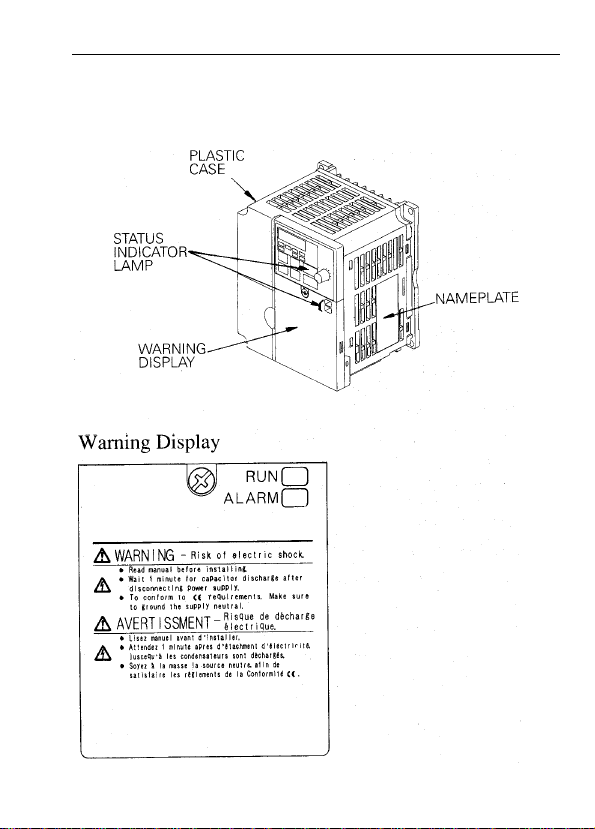
WARNING DISPL AY
A warning label is displayed on the front cover of the inverter, as shown below. Follow
these instructions when handling the inverter.
11

CONTENTS
NOTES FOR SAFE OPERATION . . . . . . . . . . . . . . . . . . . . 3
1. RECEIVING . . . . . . . . . . . . . . . . . . . . . . . . . . . . . . . . . . 14
•
Checking the Name Plate . . . . . . . . . . . . . . . . . . . . . . . . . . .14
2. IDENTIFYING THE PARTS . . . . . . . . . . . . . . . . . . . . . . 16
3. MOUNTING . . . . . . . . . . . . . . . . . . . . . . . . . . . . . . . . . . 18
•
Choosing a Location to Mount the Inverter . . . . . . . . . . . . . .18
•
Mounting Dimensions . . . . . . . . . . . . . . . . . . . . . . . . . . . . . .19
•
Mounting/Removing Components . . . . . . . . . . . . . . . . . . . . .20
4. WIRING . . . . . . . . . . . . . . . . . . . . . . . . . . . . . . . . . . . . . 22
•
Wiring Instructions . . . . . . . . . . . . . . . . . . . . . . . . . . . . . . . . .22
•
Wire and Terminal Screw Sizes. . . . . . . . . . . . . . . . . . . . . . .23
•
Wiring the Main Circuit. . . . . . . . . . . . . . . . . . . . . . . . . . . . . .25
•
Wiring the Control Circuit. . . . . . . . . . . . . . . . . . . . . . . . . . . .26
•
Wiring Inspection. . . . . . . . . . . . . . . . . . . . . . . . . . . . . . . . . .27
5. OPERATING THE INVERTER. . . . . . . . . . . . . . . . . . . . 28
•
Test Run . . . . . . . . . . . . . . . . . . . . . . . . . . . . . . . . . . . . . . . .28
•
Operating the Digital Operator. . . . . . . . . . . . . . . . . . . . . . . .30
•
LED Description. . . . . . . . . . . . . . . . . . . . . . . . . . . . . . . . . . . 32
•
Simple Data Setting. . . . . . . . . . . . . . . . . . . . . . . . . . . . . . . .37
6. PROGRAMMING FEATURES . . . . . . . . . . . . . . . . . . . . 39
•
Parameter Set-up and Initialization . . . . . . . . . . . . . . . . . . . .39
•
Using V/f control Mode . . . . . . . . . . . . . . . . . . . . . . . . . . . . .40
•
Using Vector Control Mode . . . . . . . . . . . . . . . . . . . . . . . . . .43
•
Switching LOCAL/REMOTE Modes . . . . . . . . . . . . . . . . . . .46
•
Selecting Run/Stop Commands. . . . . . . . . . . . . . . . . . . . . . .47
•
Setting Operation Condition . . . . . . . . . . . . . . . . . . . . . . . . .50
12

•
Selecting Stopping Method . . . . . . . . . . . . . . . . . . . . . . . . . .71
•
Building Interface Circuits with External Devices . . . . . . . . .73
•
Setting Frequency by Current Reference Input. . . . . . . . . . .83
•
Frequency Reference by Pulse Train Input. . . . . . . . . . . . . .85
•
Decreasing Motor Speed Fluctuation . . . . . . . . . . . . . . . . . .89
•
Motor Protection . . . . . . . . . . . . . . . . . . . . . . . . . . . . . . . . . .90
•
Selecting Cooling Fan Operation. . . . . . . . . . . . . . . . . . . . . .92
•
Using MEMOBUS (MODBUS) Communications. . . . . . . . . .92
•
Using Parameter Copy Function . . . . . . . . . . . . . . . . . . . . . 116
•
Unit Selection for Frequency Reference Setting Display. . .125
7. MAINTENANCE AND INSPECTION . . . . . . . . . . . . . .127
•
Periodical Inspection . . . . . . . . . . . . . . . . . . . . . . . . . . . . . .127
•
Part Replacement . . . . . . . . . . . . . . . . . . . . . . . . . . . . . . . .127
8. FAULT DIAGNOSIS AND CORRECTIVE ACTIONS . . 129
9. SPECIFICATIONS . . . . . . . . . . . . . . . . . . . . . . . . . . . .139
•
Standard Specifications (200V Class). . . . . . . . . . . . . . . . .139
•
Standard Specifications (400V Class). . . . . . . . . . . . . . . . .142
•
Standard Wiring. . . . . . . . . . . . . . . . . . . . . . . . . . . . . . . . . .145
•
Sequence Input Connection with NPN/PNP Transistor. . . .148
•
Dimensions . . . . . . . . . . . . . . . . . . . . . . . . . . . . . . . . . . . . .150
•
Recommended Peripheral Devices. . . . . . . . . . . . . . . . . . .153
•
Parameter List. . . . . . . . . . . . . . . . . . . . . . . . . . . . . . . . . . .154
APPENDIX . . . . . . . . . . . . . . . . . . . . . . . . . . . . . . . . . . . .167
•
CE Conformance. . . . . . . . . . . . . . . . . . . . . . . . . . . . . . . . .167
13
1. RECEIVING
After unpacking the VS-606V7, check the following:
• V erify that the part numbers match your purchase order or packing slip.
• Check the unit for physical damage that may have occurred during shipping.
If any part of VS-606V7 is missing or damaged, call for service immediately.
•
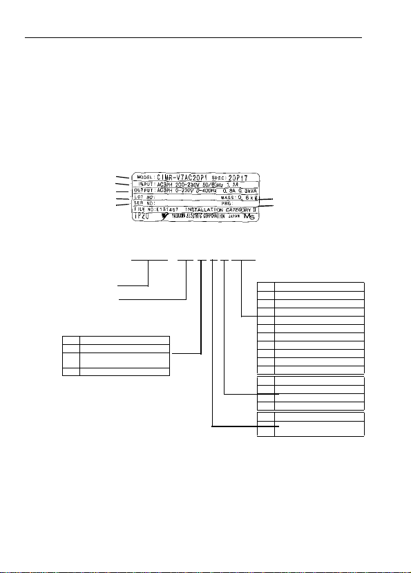
Checking the Name Plate
U.S. and Canadian Safety Standards for Types of 3-phase, 200VAC, 0.13HP (0.1kW)
INVERTER MODEL
INPUT SPEC.
OUTPUT SPEC.
LOT NO.
SERIAL NO.
MODEL
VS-606V7 SERIES
No. Type
A With digital operator (with volume)
B Without digital operator
(with volume)
C With digital operator (with volume)
Note: Contact your YASKAWA representative
for the type without heatsink.
C I M R - V 7 A U 2 0 P 1
INVERTER
MASS
SOFTWARE
No. Applicable maximum motor output
OP1 0.13 HP (0.1kW)
OP2 0.25 HP (0.2kW)
OP4 0.5 HP (0.4kW)
OP7 1 HP (0.75kW)
1P5 2 HP (1.5kW)
2P2 3 HP (2.2kW)
3PO 4 HP (3.0kW)
3P7 5 HP (3.7kW)
5P5 7.5 HP (5.5kW)
7P5 10 HP (7.5kW)
No. Voltage Class
B 0.13 HP (0.1kW)
2 0.25 HP (0.2kW)
4 0.5 HP (0.4kW)
No. Specifications
U UL Specification (U.S .
Specification)
14
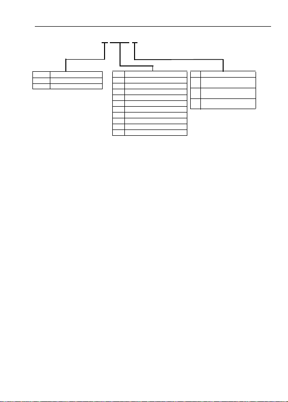
2 0 P 1 0
B Single-Phase 200VAC
2 Three-Phase 200VAC
4 Three-Phase 400VAC
No. Applicable maximum motor output
OP1 0.13 HP (0.1kW)
OP2 0.25 HP (0.2kW)
OP4 0.5 HP (0.4kW)
OP7 1 HP (0.75kW)
1P5 2 HP (1.5kW)
2P2 3 HP (2.2kW)
3PO 4 HP (3.0kW)
3P7 5 HP (3.7kW)
5P5 7.5 HP (5.5kW)
7P5 10 HP (7.5kW)
*1 Code No.s OP1 to 3P7 are IP20.
Always remove both top and bottom covers
when using the 5P5 and 7P5 inverters as
open chassis types IP00.
*2 NEMA 1 “OP1” to “3P7” are optional.
NEMA 1 “5P5” and “7P5” are standard.
No. Protective structure
0 Ope n chassis
1 Enclosed wall-mounted
7 Open chassis (IP20)
(IP20, IP00) *1
(NEMA 1) *2
Top-closed type
15
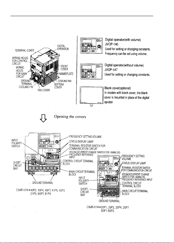
2. IDENTIFYING THE PARTS
16
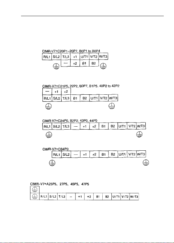
Main Circuit Terminal Arrangement
Terminal arrangement of the main circuit terminal differs depending on the inverter
model.
The terminal arrangement for200/400V, 3-Phase input series 7.5/10 HP (5.5/7.5Kw) is
shown below.
17

3. MOUNTING
•
Choosing a Location to Mount the Inverter
Be sure the inverter is protected from the following conditions:
• Extreme cold and heat. Use only within the ambient temperature range (for open
chassis type): 14 to 122°F (-10 to +50°C).
• Rain, moisture.
• Oil sprays , sp lashes.
• Salt spray.
• Direct sunlight. (Avoid using outdoors).
• Corrosive gases (e.g. sulfurized gas) or liquids.
• Dust or metallic particles in the air.
• Physical shock, vibration.
• Magnetic noise. (Example: welding machines, power devices, etc.)
• High humidity.
• Radioactive substances.
• Combustibles: thinner, solvents, etc.
18
aa
A
• Mounting Dimensions
To mount the VS 606 V7, dimensions as shown below are required.
Voltage
200V Single - phase
3 - phase
400V 3 - phase
200V 3 - phase
400V 3 - phase
Max. Applicable
Motor Output
HP (Kw)
Less than
5 HP (3.7 Kw)
7.5 HP (5.5 Kw) More than
10 HP (7.5 Kw)
Length of A
More than
1.18in (30mm)
1.97in (50mm)
Caution!
1. The above dimensions are common for both open chassis type (IP00, IP20) and
NEMA 1 type.
2. Always remove both top and bottom covers when using 200/400V, 5.5/7.5Kw
(7.5/10 HP) as open chassis type.
19
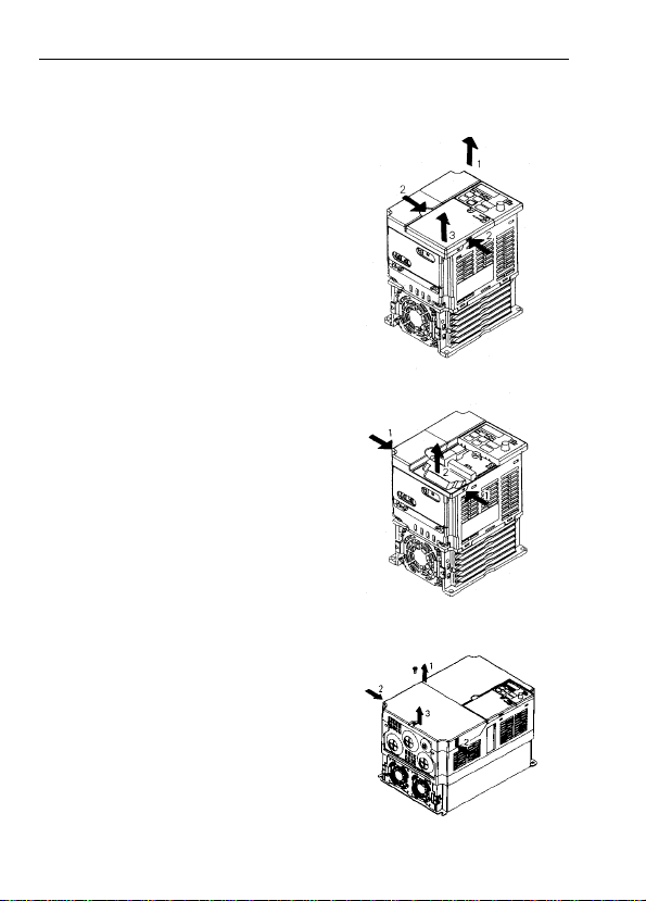
• Mounting/Removing Components
Removing and Mounting Digital Operator and Covers
NOTE:
Mount the inverter after removing the
front cover, digital operator and terminal
cover.
• Removing front cover
Use a screwdriver to loosen the screw on
the front cover surface to direction 1 to
remove it. Then press the right and left
sides to direction 2 and lift the front cover
to direction 3.
• Mounting front cover
Mount the front cover in the reverse order
of the above procedure for removal.
• Removing terminal cover when “W”
(Width) dimensions are 4.25” (108mm),
5.51” (140mm), or 6.69” (170mm)
After removing the front cover, press the
right and left sides to direction 1 and lift
the terminal cover to direction 2.
.
• Removing terminal cover when “W”
(Width) dimensions are 7.09” (180mm)
Use a Screwdriver to loosen the screw on
the terminal cover surface to direction 1 to
remove it. Then press the right and left
sides to direction 2 and lift the terminal
cover to direction 3.
• Mounting terminal cover
Mount the terminal cover in the
descending order of the above procedure
for removal.
20
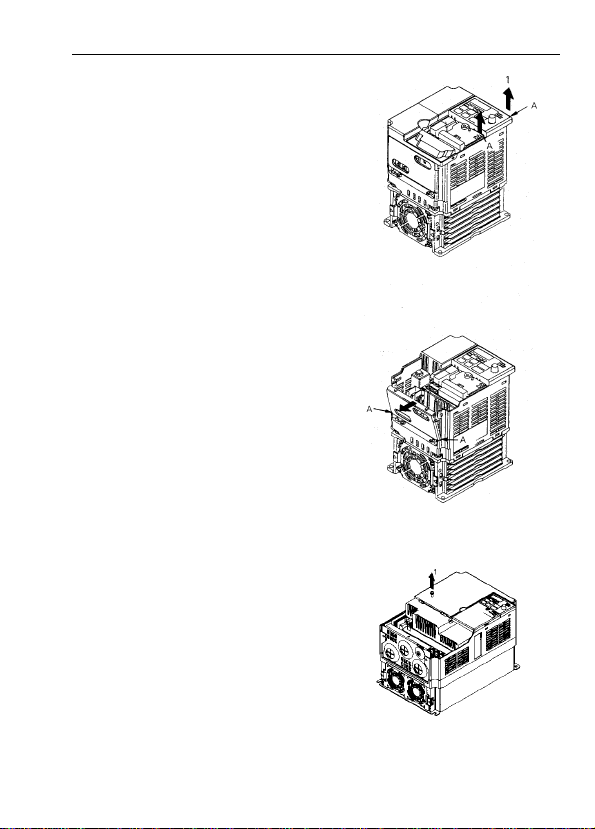
• Removing digital operator
After removing the front cover, lift the
upper and lower sides (section A) of the
right side of the digital operator to
direction 1.
• Mounting digital operator
Mount the digital operator in the reverse
order of the above procedure for removal.
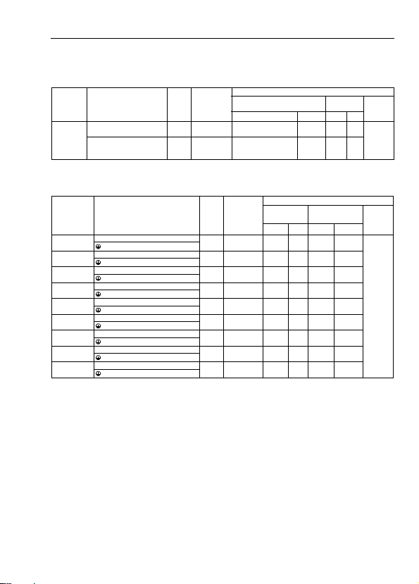
• Removing bottom cover when “W”
(Width) dimensions are 4.25” (108mm),
5.51” (140mm), or 6.69” (170mm)
After removing the front cover and the
terminal cover, tilt the bottom cover to
direction 1 with section A as a supporting
point.
• Removing terminal cover when “W”
(Width) dimensions are 7.09” (180mm)
After removing the terminal cover use a
screwdriver to loosen the fastening screw
to loosen the fastening screw to direction 1
to remove it.
• Mounting bottom cover
Mount the bottom cover in the reverse
order of the above procedure for removal.
21

4. WIRING
• Wiring Instructions
(1) Always connect the power input terminals R/L1, S/L2, and T/L3 (R/L1, S/L2 for
single-phase) and power supply via a molded-case circuit breaker (MCCB). Never
connect them to U/T1, V/T2, W/T3.
The single-phase (200V class) inverter can be connected to a 200V 3-phase input.
However, when terminal T/L3 is connected to single-phase, never use the terminal
for other purposes.
200V 3-phase Input Power Supply
Specification Product
CIMR-V7……2
Connect to R/L1, S/L2, T/L3 Connect to R/L1, S/L2 Connect to R/L1, S/L2, T/L3
(2) Connect the motor wiring to terminals U, V, and W on the main circuit output side
(bottom of the inverter).
(3) If the wiring distance between inverter and motor is long, reduce the inverter
carrier frequency. For details, refer to “Reducing motor noise or leakage current
(n46)” on page 68.
(4) Control wiring must be less than 164ft(50m) in length and separate from the power
wiring. Use twisted-pair shielded wire when inputting the freque ncy signal
externally.
(5) Tighten the screws on the main circuit and control circuit terminals.
(6) Do not connect or disconnect wiring, or perform signal check while the power
supply is turned ON.
(7) For 400V class inverters, make sure to ground the supply neutral to conform to CE
requirements.
(8) A closed-loop connector should be used when wiring to the main circuit terminal.
(9) Voltage drop should be considered when determining wire size.
Voltage drop can be calculated using the following equation:
Phase- to phase voltage drop (V) = √3 wire resistance (Ω/km) x wiring distance
(m) x current (A) x 10
Select a wire size so that voltage drop will be less than 2% of the normal rated
voltage.
Inverter Power Supply Connection Terminals
200V Single Input Power Supply
Specification Product.
………
CIMR-V7……B
-3
………
400V 3-phase Input Power Supply
Specification Product
CIMR-V7……4
………
22
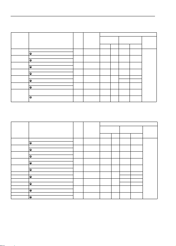
• Wire and Terminal Screw Sizes
1. Control Circuit
Tightening
M2
Torqu e
lb • in (N • m)
4.44 to 5.33
(0.5 to 0.6)
1.94 to 2.21
(0.22 to 0.25)
Model Terminal Symbol Screw
to
S1 to S7,P1, P2,SC,PC,R+,
MA, MB, MC M3
R-,S+,S-
,FS,FR,FC,AM,AC,RP
Common
all models
2. Main Circuit
200V Class 3-phase Input Series
Model Terminal Symbol Screw
R/L1,S/L2,T/L3,-,+1,+2,B1,B2,U/T1,V/T2,W/T3
CIMR-V7AA20P1
R/L1,S/L2,T/L3,-,+1,+2,B1,B2,U/T1,V/T2,W/T3
CIMR-V7AA20P2
R/L1,S/L2,T/L3,-,+1,+2,B1,B2,U/T1,V/T2,W/T3
CIMR-V7AA20P4
R/L1,S/L2,T/L3,-,+1,+2,B1,B2,U/T1,V/T2,W/T3
CIMR-V7AA20P7
R/L1,S/L2,-,+1,+2,B1,B2,U/T1,V/T2,W/T3
CIMR-V7AA21P5
R/L1,S/L2,T/L3,-,+1,+2,B1,B2,U/T1,V/T2,W/T3
CIMR-V7AA22P2
R/L1,S/L2,T/L3,-,+1,+2,B1,B2,U/T1,V/T2,W/T3
CIMR-V7AA24PO
R/L1,S/L2,T/L3,-,+1,+2,B1,B2,U/T1,V/T2,W/T3
CIMR-V7*A25P5
R/L1,S/L2,T/L3,-,+1,+2,B1,B2,U/T1,V/T2,W/T3
CIMR-V7*A27P5
M3.5
M3.5
M3.5
M3.5
M4
M4
M4
M5
M5
Note: The wire size is set for copper wires at 160°F (75°C)
Applicable size
mm
twisted wire 0.5 to 1.25
single 0.5 to 1.25
twisted wire 0.5 to 0.75
single 0.5 to 1.25
Tightening
Torq ue
lb • in
(N • m)
7.1 to 8.88
(0.8 to 1.0)
7.1 to 8.88
(0.8 to 1.0)
7.1 to 8.88
(0.8 to 1.0)
7.1 to 8.88
(0.8 to 1.0)
10.65 to 13.31
(1.2 to 1.5)
10.65 to 13.31
(1.2 to 1.5)
10.65 to 13.31
(1.2 to 1.5)
22.19
(2.5)
22.19
(2.5)
Wire
Recommend
2
AWG
mm
20 to 16
0.75 18
20 to 16
20 to 18
0.75 18
20 to 16
size
2
AWG
18 to
18 to
18 to
18 to
14 to
14 to
14 to
14
14
14
14
10
10
10
Wire
Recommended
size
2
mm
214
214
214
214
214
3.5 12
5.5 10
Applicable
mm
0.75 to 2
0.75 to 2
0.75 to 2
0.75 to 2
2 to 5.5
2 to 5.5
2 to 5.5
5.5 to 8 10 to 8 8 8
5.5 to 8 10 to 8 8 8
size
2
AWG
AWG
Type
Shielded
wire or
equivalent
Type
600V
vinyl-
sheathed
wire or
equivalent
23
200V Class Single-phase Input Series
Model Terminal Symbol Screw
Tightening
R/L1,S/L2,T/L3,-,+1,+2,B1,B2,U/T1,V/T2,W/T3
CIMR-V7AAB0P1
R/L1,S/L2,T/L3,-,+1,+2,B1,B2,U/T1,V/T2,W/T3
CIMR-V7AAB0P2
R/L1,S/L2,T/L3,-,+1,+2,B1,B2,U/T1,V/T2,W/T3
CIMR-V7AAB0P4
R/L1,S/L2,T/L3,-,+1,+2,B1,B2,U/T1,V/T2,W/T3
CIMR-V7AAB0P7
R/L1,S/L2,T/L3,-,+1,+2,B1,B2,U/T1,V/T2,W/T3
CIMR-V7AAB1P5
R/L1,S/L2,T/L3,-,+1,+2,B1,B2,U/T1,V/T2,W/T3
CIMR-V7AAB2P2
R/L1,S/L2,T/L3,-,+1,+2,B1,B2,U/T1,V/T2,W/T3
CIMRV7AAB4PO
M3.5
M3.5
M3.5
M4
M4
M4
M5
M4
10.65 to 13.31
10.65 to 13.31
10.65 to 13.31
10.65 to 13.31
Note: The wire size is set for copper wires at 160°F (75°C)
Note: Three-phase input is also available for 0.1 to 0.75kw of single-phase input
series.
Torq u e
lb • in
(N • m)
7.1 to 8.88
(0.8 to 1.0)
7.1 to 8.88
(0.8 to 1.0)
7.1 to 8.88
(0.8 to 1.0)
(1.2 to 1.5)
(1.2 to 1.5)
(1.2 to 1.5)
26.62
(3.0)
(1.2 to 1.5)
Applicable
size
2
mm
0.75 to 2
0.75 to 2
0.75 to 2
2 to 5.5
2 to 5.5
2 to 5.5
3.5 to 8
2 to 8
AWG
18 to
14
18 to
14
18 to
14
18 to
14
14 to
10
14 to
10
12 to
14 to
8
8
Recommended
mm
3. 5 12
5.5 10
3.5 12
5.5 10
5.5 10
400V Class 3-phase Input Series
Model Terminal Symbol Screw
Tightening
R/L1,S/L2,T/L3,-,+1,+2,B1,B2,U/T1,V/T2,W/T3
CIMR-V7AA40P2
R/L1,S/L2,T/L3,-,+1,+2,B1,B2,U/T1,V/T2,W/T3
CIMR-V7AA40P4
R/L1,S/L2,T/L3,-,+1,+2,B1,B2,U/T1,V/T2,W/T3
CIMR-V7AA40P7
R/L1,S/L2,T/L3,-,+1,+2,B1,B2,U/T1,V/T2,W/T3
CIMR-V7AA41P5
R/L1,S/L2,T/L3,-,+1,+2,B1,B2,U/T1,V/T2,W/T3
CIMR-V7AA42P2
CIMR-V7AA43P0 R/L1,S/L2,T/L3,-,+1,+2,B1,B2,U/T1,V/T2,W/T3
CIMR-V7AA44PO R/L1,S/L2,T/L3,-,+1,+2,B1,B2,U/T1,V/T2,W/T3
CIMR-V7*A45P5 R/L1,S/L2,T/L3,-,+1,+2,B1,B2,U/T1,V/T2,W/T3
CIMR-V7*A47P5 R/L1,S/L2,T/L3,-,+1,+2,B1,B2,U/T1,V/T2,W/T3
M4
M4
M4
M4
M4
M4
M4
M4
M5
10.65 to 13.31
10.65 to 13.31
10.65 to 13.31
10.65 to 13.31
10.65 to 13.31
10.65 to 13.31
10.65 to 13.31
Note: The wire size is set for copper wires at 160°F (75°C)
Torq u e
lb • in
(N • m)
(1.2 to 1.5)
(1.2 to 1.5)
(1.2 to 1.5)
(1.2 to 1.5)
(1.2 to 1.5)
(1.2 to 1.5)
(1.2 to 1.5)
12.43
(1.4)
22.19
(2.5)
Applicable
size
2
mm
2 to 5.5
2 to 5.5
2 to 5.5
2 to 5.5
2 to 5.5
2 to 5.5
2 to 5.5
3.5 to 5.5
5.5 to 8
AWG
14 to
10
14 to
10
14 to
10
14 to
10
14 to
10
14 to
10
14 to
10
12 to
10
12 to
10
Recommended
mm
3.5 12
3.5 12
5.5 10
5.5 10
Wire
size
2
AWG
214
214
214
88
Wire
size
2
AWG
214
214
214
214
214
214
214
Type
600V vinyl-
sheathed
wire or
equivalent
Type
600V vinyl-
sheathed
wire or
equivalent
24
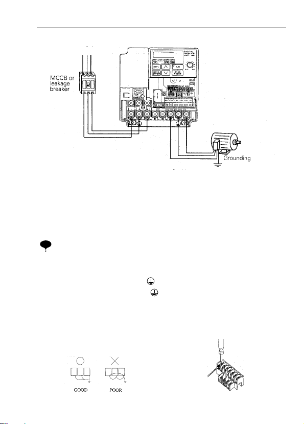
• Wiring the Main Circuit
L1 L2 L3
• Main circuit input power supply
Connect the power supply wiring to input
terminals L1 (R), N/L2(S) and L3(T)
[L1(R), N/L2(S) for single-phase
specifications]. Never connect them to U/
T1, V/T2, W/T3, B1, B2, -, +1, or +2.
Otherwise the inverter may be damaged.
Single-phase voltage may be connected to
inverter but do not use terminal T/L3 for
any other purposes.
Single-phase (200V class, 0.75kW
NOTE
or less) voltage may be connected
to terminal T/L3. Never use the terminal with other purposes.
• Grounding (Use ground terminal .)
Make sure to ground the ground terminal
according to the local grounding code.
Never ground the VS-606V7 in common
with welding machines, motors, or other
electrical equipment.
When several VS-606V7 units are used
side by side, ground each unit as shown in
examples. Do not loop the ground wires.
[Example of 3-phase
400V class, 0.37
inverters]
• Braking resistor connection
(optional).
To connect the braking resistor, cut the
protector on terminals B1 and B2.
To protect the braking resistor from
overheating, install a thermal overload
relay between the braking resistor and the
inverter. This provides a sequence which
shuts off the power supply, by a thermal
relay trip contact.
Use this same procedure when connecting
a braking resistor unit. Refer to page 104.
• Inverter output
Connect the motor terminals to U, V, W.
Wiring the main circuit termina ls
Pass the cables through wiring hole and
connect. Be sure to mount the cover in its
original position.
25
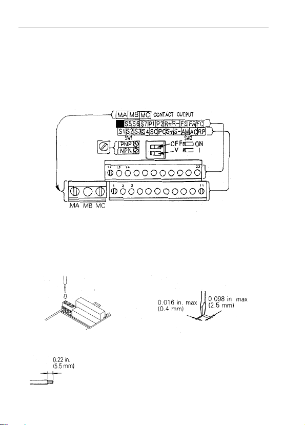
• Wiring the Control Circuit
Only basic insulation is provided for the control circuit terminal s.
Additional insulation may be necessary in the end product.
• Control Circuit terminals
Pass the cable through wiring hole and connect. Be sure to mount all the covers on the
original position.
* SW1 can be changed according to sequence input
signal (S1 to S7) polarity.
0V common: NPN side (factory setting)
24 common: PNP side
Refer to pages 67 and 76 for SW2
Wiring the control circuit terminals
Screwdriver blade width
Insert the wire into the lower part of the terminal block and connect it tightly with a
screwdriver.
Wire sheath strip length must be 0.22 in. (5.5mm).
26
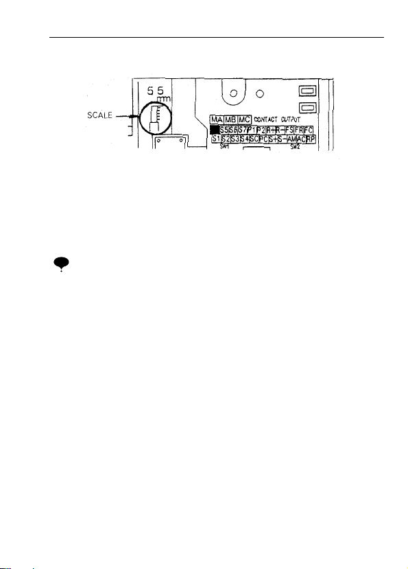
Open the front cover and verify that the strip length is 0.22 in. (5.5mm)
• Wiring Inspection
After completing wiring, check the following:
• Wiring is properly connected.
• Wire clippings or screws are not left inside the unit.
• Screws are securely tightened.
• Bare wires in the terminal do not come in contact with other terminals.
If the FWD (REV) run command is given during the operation reference selec-
NOTE
tion (n003=1) from the control circuit terminal, the motor will start automatically
after the main circuit input power supply is turned ON.
27

5. OPERATING THE INVERTER
Initial setting of control mode selection (n002) is set at V/f control mode.
•
Test Run
The inverter operates by setting the frequency (speed).
There are three types of operation modes for the VS-606V7:
1. Run command from the digital operator (local pote ntiometer/digital setting).
2. Run command from the control circuit terminal.
3. Run command from communications (MEMOBUS communications).
Prior to shipping, the drive is set up to receive run command and frequency reference
from the operator. Below are instructions for running the VS-606V7 using the digital
operator JVOP-140 (with local potentiometer) or optional JVOP-147 (without local
potentiometer. For instructions on operation, refer to page 37.
Operation reference or frequency reference parameters can be selected separately as
shown below.
Name parameter
Operation Reference
Selection
Frequency Reference
Selection
N003 = 0 --- Enables operator RUN, STOP/RESET
= 1 --- Enables control circuit terminal run/stop
= 2 --- Enables communications (MEMOBUS communications)
= 3 --- Enables communication card (optional)
N004 = 0 --- E nables digital operator potentiometer
= 1 --- Enables frequency reference 1 (parameter 024)
= 2 --- Enables voltage reference (0 to 10V) of control circuit terminal
= 3 --- Enables current reference (4 to 20mA) of control circuit terminal
= 4 --- Enables current reference (0 to 20mA) of control circuit terminal
= 5 --- Enables pulse line reference of control circuit terminal
= 6 --- Enables communications (MEMOBUS communications)
= 7 --- Enables voltage reference (0 to 10V) of operator circuit terminal
= 8 --- Enables current reference (4 to 20 mA) of operator circuit terminal
= 9 --- Enables communication card (optional)
28
1.Turn ON the power supply. 6.00
2. Set parameter n004 to 1. 1
3.Set the following parameters.
n019 : 15.0 (acceleration time)
n020 : 5.0 (deceleration time)
4.F/R blinks.
Select Forward or reverse run by pressing or key.
NOTE
5.Set the reference by pressing or key.
6. Press
Operation Steps
Examine the application.
(Never select REV when reverse run
is prohibited.)
RUN
Operator
Display
15.0
5.0
(Forward)
or
(Reverse)
60.00 RUN
0.00 60.0 RUN
12-LED
Display
FREF
PRGM
PRGM
F /R
Status
Indicator LED
RUN
ALARM
RUN
ALARM
RUN
ALARM
RUN
ALARM
FREF
ALARM
FOUT
ALARM
7. Press
STOP
to stop.
Status indicator lamp
: Blinking (Long Blinking)
: ON
60.0 00.0 RUN
Operation Check Points
• Motor rotates smoothly.
• Motor rotates in the correct direction.
• Motor does not have abnormal vibration or noise.
• Acceleration or deceleration is smooth.
• Current matching the load flows.
• Status indicator LED’s and digital operator display are correct.
FOUT
: Blinking
ALARM
:OFF
29
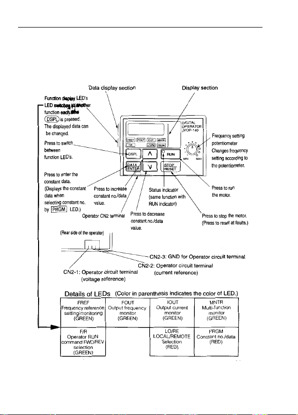
• Operating the Digital Operator
All functions of the VS-606V7 are set by the digital operator. Below are descriptions of
the display and keypad sections.
Digital Operator JVOP-140
30

Description of Status Indicator LED’s
RUN
There are two LED’s on the middle right section of the face of the VS-606V7. The
inverter status is indicated by various combinations of ON, BLINKING and OFF
LED’s. RUN indicator and status indicator of the button have the same
functions.
For details on how the status indicator LED’s function at inverter faults, refer to
Section 8 “FAULT DIAGNOSIS AND CORRECTIVE ACTIONS” on page 126. If a
fault occurs, the ALARM LED lights.
NOTE
The fault can be reset by turning ON the fault reset signal (or pressing key
on the digital operator) with the operation signal OFF or by turning OFF the
power supply. If the operation signal is ON, the fault cannot be reset by the fault
reset signal.
STOP
RESET
31

• LED Description
By pressing on the digital operator, each of the function LED’s can be
selected.
The following flowchart describes each function LED.
If the VS-606V7
loses power while in
one of these modes,
it will return to this
mode once power is
restored.
32

Return to
Multi-Function monitor
• Selecting monitor
Press key. When is ON, data can be displayed by
selecting monitor No.
[Example] Monitoring Output Voltage Reference
41
33

• Monitoring
Following items can be monitored by U-parameter
parameter
No.
U-01
U-02
U-03
U-04 Output voltage V Output voltage can be monitored.
U-05 DC voltage V Main circuit DC voltage can be monitored.
U-06 Input terminal status*
U-07 Output terminal status*
U-08 Torque monitor %
U-09 Fault history (last 4 faults) — Last four fault history is displayed.
U-10 Software No. — Software No. can be checked.
U-11 Output power*
U-13 Cumulative operation time*
U-15 Data reception error*
U-16 PID feedback*
U-17 PID input*
U-18 PID output*
*1 The status indicator LED is not turned ON.
*2 Refer to the next page for input / output terminal status.
*3 The display range is from -99.9kW to 99.99kW.
When regenerating. the output power will be displayed in units of 0.01kW when
-9.99kW or less and in units of 0.1kW when more than -9.99kW.
When in the vector control mode, “----” will be displayed.
*4 This function only applies to 200/400V class 7.5/10hp (5.5/7.5kW) inverters.
*5 Displayed in units of 0.1% when less than 100% and in units of 1% when 100% or
more. The display range is from -999% to 999%.
Name Description
Frequency reference
(FREF)*
¹
Output frequency
(FOUT)*
¹
Output current
(IOUT)*
¹
3
5
5
5
Frequency reference can be monitored.
Hz
(Same as FREF)
Output frequency can be monitored.
Hz
(Same as FOUT)
Output current can be monitored.
Hz
(Same as IOUT)
Input terminal status of control circuit terminals can be
2
—
monitored.
Output terminal status of control circuit terminals can
2
—
be monitored.
The amount of output torque can be monitored. When
V/f control mode is selected, “----” is displayed.
kW Output power can be monitored
Cumulative operation time can be monitored in units of
4
x10H
10H
Contents of MEMOBUS communication data reception
4
—
error can be checked. (contents of transmission
register No. 003DH are the same)
% Input 100(%) / Max. output frequency or equivalent
% + 100(%) /+ Max. output frequency
% + 100(%) /+ Max. output frequency
34

35

Fault history display method
When U-09 is selected, a four-digit box is displayed. The three digits from the right
show the fault description, and the digit on the left shows the order of fault (from one to
four). Number 1 represents the latest fault, and 2, 3, 4, in ascending order of fault
occurrence.
(Example)
(Refer to page 126 for details.)
• Switching fault history
Order of the fault history can be changed by or key.
• Clearing fault history
Set parameter n001 to 6 to clear fault history. Display returns to n001 after
completion of 6 setting.
Note: parameter initialize (n001 = 10, 11) clears the fault history.
Setting and referring parameters
36

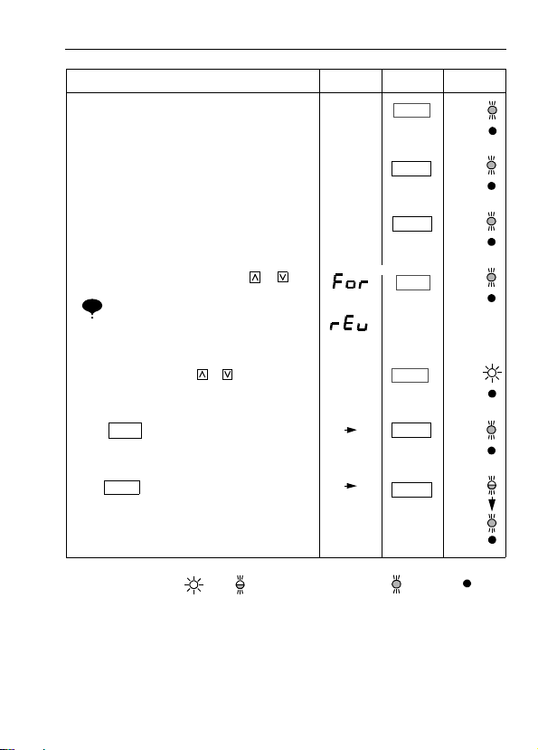
• Simple Data Setting
Digital setting (Refer to 5, OPERA T ING THE INVER T ER) and potentiometer setting
are both available for simple accel/decel operation of the VS-606V7.
Frequency reference by analog voltage is set with initial setting (n004 = 1). For the
model with digital operator (with potentiometer) JVOP-140, factory setting is set by
frequency setting potentiometer (n004=0).
Following is an example in which the function LED’s are used to set frequency
reference, acceleration time, deceleration time, and motor direction.
Data setting by frequency setting potentiometer
Operation Steps
1. Turn the potent iometer fully to the left. Then, tur n
the power ON.
2. F/R blinks.
Select FWD/REV run using keys.
Never select REV when reverse run is
NOTE
prohibited.
Operator
Display
0.00
FOR
or
REV
12-LED
Display
FREF
F/R
Status
Indicator LED
RUN
ALARM
RUN
ALARM
3. Press DSPL to blink FREF. Then press RUN. 0.00
4. Operates the motor by turning the potentiometer
to the right. (Frequency reference corresponds to
the potentiometer position is displayed.)
If the potentiometer is switched rapidly,
NOTE
the motor also accelerates or decelerate s
rapidly corresponding to the
potentiometer movement. Pay attention
to load status and switch the
potentiometer movement.
Status indicator lamp
: Blinking (Long Blinking)
: ON
00.0 to
60.00
Minimum
output
frequency is
1.50Hz
FREF
FREF
: Blinking
RUN
ALARM
RUN
ALARM
:OFF
37

Notes
38

6. PROGRAMMING FEATURES
Factory settings of the parameters are shown as in the tables.
•
Parameter Set-up and Initialization
Parameter selection/initialization (n001)
The following table describes the data which can be set or read when n001 is set.
Unused parameters among n001 to n179 are not displayed.
n001 Setting Parameter that can be set Parameter that can be referred
0 n001 n001 to n179
1 n001 to n049* n001 to n049
2 n001 to n079* n001 to n079
3 n001 to n119* n001 to n119
4 n001 to n179* n001 to n179
5 Not used
6 Fault history cleared
8,9,12,13 Not used
10 Initialize
11 Initialize (3-wire sequence)
* Excluding setting disabled parameters.
=
Refer to page 70.
NOTE
“ ” appears on the LED display for one second and the set data returns to
its initial values in the following cases:
(1) The set values of input terminal function selection 1 to 7 (n050 to n056) are the
same.
(2) The following conditions are not satisfied in the V/f pattern setting:
Max. output frequency (n011) >
> Mid. output frequency (n014)
>
Min. output frequency (n016)
For details, refer to “Adjusting torque according to application” (V/f pattern setting) on page 38.
(3) If the following conditions are not satisfied in the Jump frequency setting:
Jump frequency 3 (n085)<
(4) If Frequency reference lower limit (n034) >
(n033)
(5) If motor rated current (n036) >
(6) When n018 = 0 and n019 ~ n022 is set to a value greater than 600.0 sec, parameter
n018 will automatically be set to 1.
=
Max. voltage output frequency (n013)
Jump frequency 2 (n084)
<
Jump frequency 1 (n083)
Frequency reference upper limit
150% of inverter rated current
39

•
Using V/f Control Mode
Vector control mode is preset at the factory.
Control mode selection (n002): 0: V/f control mode (initial setting)
1: Vector control mode
Adjusting torque according to application
Adjust motor torque by using “V/f pattern” and “full-range automatic torque boost”.
• V/f pattern setting
Set V/f pattern by n011 to n017 as described below. Set each pattern when using a
special motor (high-speed motor, etc.) or when requiring special torque adjustment
of machine.
Be sure to satisfy the following
conditions for the setting of n011
to n017.
n014 < n013 < n011
n016 <
If n016 = n014 is set, the set
value of n015 is disabled.
n016 n014 n013 n011 (frequency)
Parameters
No.
n011 Max. output frequency 0.1Hz 50.0 to 400.0Hz 60.0Hz
n012 Max. voltage 1V
Max. voltage output frequency
n013
(base frequency)
n014 Mid. output frequency 0.1Hz 0.1 to 399.9Hz 1.5Hz
n015 Mid. output frequency voltage 1V
n016 Min. output frequency 0.1Hz 0.1 to 10.0Hz 1.5Hz
n017 Min. output frequency voltage 1V
* 10.0V for 200V class 7.5/10hp (5.5/7.5kW)
20.0V for 400V class 7.5/10hp (5.5/7.5kW)
NOTE: Values with parentheses indicate 400V class.
Name Unit Setting range Initial Setting
1 to 255.0V
0.1Hz 0.2 to 400.0Hz 60.0Hz
(0.1 to 510.0V)
0.1 to 255.0V
(0.1 to 510.0V)
1 to 50.0V
(0.1 to 100.0V)
40
230.0V
(460.0V)
12.0V
(24.0V)
4.3V *
(8.6V)

• Typical setting of V/f pattern
Set the V/f pattern according to the application as described below . For 400V class,
the voltage values (n012, n015, and n017) should be doubled. When running at a
frequency exceeding 50Hz/60Hz, change the maximum output frequency (n011).
Note: Be sure to set the maximum output frequency according to the motor char-
acteristics
(Factory setting)
Increasing voltage of V/f pattern increases motor torque, but excessive increase may
cause motor over excitation, motor overheat, or vibration.
Note: n012 is to be set to motor rated voltage.
41

•
Full-range automatic torque boost (when V/f mode is selected. n002=0)
Motor torque requirement changes according to load conditions. Full range
automatic torque boost adjusts voltage of V/f pattern according to the requirement.
The VS-606V7 automatically adjusts the voltage during parameter-speed operation
as well as during acceleration.
The required torque is calculated by the inverter.
This ensures tripless operation and energy-saving effects.
Output voltage Torque compensation gain (n103) Required torque
∝
×
• Operation
Normally, no adjustment is necessary for torque compensation gain (n103 factory
setting: 1.0). An excessively high setting of torque compensation gain will res ult in
motor over excitation, and possible inverter faults. If adjustments are necessary , adjust
n103 in increments/decrements of 0.1 for optimization. When wiring distance between
the inverter and the motor are long it may be necessary to increas e t he setting of n103.
When motor generates vibration, decrease the setting of n103.
Adjustment of torque compensation time parameter (n104) and torque iron loss
compensation parameter (n105) are normally not required.
Adjust torque compensation parameter under the following conditions:
• Increase setting when the motor generates vibration.
• Reduce setting when motor response is low.
42

•
Using Vector Control Mode
Setting the control mode selection (n002) can use a vector control mode.
n002=0: V/f control mode (factory setting)
1: Vector control mode
Precaution for voltage vector control application
•
Since vector control needs motor parameters, the YASKAWA standard motor
parameters have been set at the factory prior to shipment. Therefore, when an
inverter exclusive-use motor is used or when a motor of any other manufacturer is
driven, the required torque characteristics or speed control characteristics may not
be maintained because the parameters are not matched. Set the following
parameters so that they can match the motor parameters.
No. Name Unit Setting range
n106 Motor rated slip 0.1Hz 0.0 to 20.0Hz
n107 Motor resistance per phase
n036 Motor rated current 0.1A
n110 M oto r no-load current 1%
∗
Setting depends on inverter capacity.
=
0.001
Ω
(less than 10Ω)
0.01
Ω
(10Ω or more)
0.000 to 65.5
0 to 150% of inverter rated
current
0 to 99%
(100%=motor rated current)
Ω∗
Initial
Setting
150
To adjust for slip compensation gain (n111), induce load so that motor speed
reaches target value. Increase or decrease the value by 0.1.
• When speed is less than target value, increase slip compensation gain.
• When speed is more than target value, reduce slip compensation gain.
Adjustment of slip compensation gain time parameter (n112) is normally not
required.
Adjust under the following conditions:
• Reduce the setting when response is low.
• Increase the setting when speed is unstable.
∗
∗
43

Select slip compensation status during regeneration
N113 Setting Slip Compensation during Regeneration
0Disabled
1 Enabled
Motor parameter calculation
•
The following shows an example of motor parameter calculation:
(1) Motor rated slip (n106)
×
120 motor rated frequency (Hz)
------------------- ----------------------------- --------------------------------- ----------- -
Number of motor pole
------------------ ------------------------------ --------------------------------- ------------------------------ ----------------------------- ------------------------------- -
=
120/Number of motor pole
(2) Motor resistance for one phase (n107)
Calculations are based on line-to-line resista nc e and insulation grade of the motor
test report.
(E type insulation) Test report of line-to-line resistance at 75°C (
(B type insulation) Test report of line-to-line resistance at 75°C (
(F type insulation) Test report of line-to-line resistance at 115°C (
(3) Motor rated current (n036)
= Rated current at motor rated freque ncy (Hz) *1 (A)
*1
Motor rated speed (r/min)
–
Ω) x 0.92 x 1/2
Ω) x 0.92 x 1/2
Ω) x 0.87 x 1/2
*2
(4) Motor no-load current (n110)
No-load current (A) at motor rated frequency (Hz)
--------------------------------------------------------------------------------------------------------- -
=
Rated current (A) at motor rated frequency (Hz)
*1 Base frequency (Hz) during rated output current.
*2 Rated speed (r/min) at base frequency during rated output current.
Set n106 (motor rated slip), n036 (motor rated current), n107 (motor resistance per
phase) and n110 (motor no-load current) according to the motor test report.
When connecting a reactor between the inverter and the motor, set n108 to the value of
n108 (motor leaking inductance) initial value + externally-mounted reactor inductance.
*1
×
100%
*1
Initial setting should be used unless a reactor is installed.
Unless a reactor is connected, n108 (motor leakage inductance) does not have to be set
according to the motor.
44

V/f pattern during vector control
•
Set V/f pattern as follows during vector control.
The following examples are for 200V class motors. When using 400V class motors,
double voltage settings (n012, n015, n017).
When operating with frequency larger than 60Hz/50Hz, change only maximum output
frequency (n011).
PARAMETER TORQUE VARIABLE OUTPUT
PARAMETER OUTPUT
= 50Hz
45

•
Switching LOCAL/REMOTE Modes
The following functions can be selected by switching the LOCAL or REMOTE
mode. To select RUN/STOP commands or frequency reference, change the mode
in advance depending on the following applications.
• LOCAL mode: Enabl es the digital operator for RUN/STOP commands and
• REMOTE mode: Enables operation reference selection (n003).
How to select LOCAL/REMOTE modes
•
FWD/REV run commands. Frequency reference can be set by
local potentiometer or .
46

•
Selecting Run/Stop Commands
Refer to Switching LOCAL/REMOTE Modes (Page 44) to select either the
LOCAL mode or REMOTE mode.
Operation method (RUN / STOP commands, FWD / REV run commands) can be
selected by the following method.
LOCAL Mod e
•
When Lo (local mode) is selected by digital operator ON mode, or
when the LOCAL / REMOTE switching function is set and the input terminals are
turned ON, run operation is enabled by the or of the digital operator,
and FWD/REV run is selected by ON mode (using or key).
REMOTE mode
•
• Select remote mode.
The following two methods are used to select remote mode:
1. Select rE (remote mode) by
2. When the local / remote switching function is sele cte d by multi-function
input selection, turn OFF the input terminal to select remote mode.
• Select operation method by setting the parameter n003.
n003 =0: Enables the digital operator (same with local mode)
=1: Enables the multi-function input terminal (see fig. below)
=3: Enables communication card (optional)
Below shows the example of three-wire sequence, (Refer to page 70.)
=2: Enables communications
• Example for using the multi-function input terminal as operation reference
(two-wire sequence)
selection.
)
For example of three-wire sequence, refer to page 70
Note: When inverter is operated without the digital operator, always set the
parameter n010 to 0.
47

Operating (RUN /STOP commands) by communications
•
Setting parameter n003 to 2 in REMOTE mode can give RUN / STOP commands
by communication (MEMOBUS communications). For the command by
transmission, refer to page 89).
Selecting Frequency Reference
•
Frequency reference can be selected by the following methods.
Setting by operator
•
Select REMOTE or LOCAL mode in advance. For the method of selecting the
mode, refer to page 44.
LOCAL mode
Select command method by parameter n008.
n008 =0 : Enables the setting by potentiometer on digital operator.
=1 : Enables the digital set ting by digita l opera tor. (Initial Setting)
F ac t o r y s et t in g o f th e m o de l wi th d ig it a l o pe r at or ( wi th
potentiometer) JVOP-140 is n008=0.
• Digital setting by digital operator
Input frequency while FREF is lit (press ENTER after setting the nume ric value).
Frequency reference setting is effective when 1 (initial setting : 0) is set to
parameter n009 instead of pressing ENTER key.
n009 =0 : Enables frequency reference setting by ENTER key.
=1 : Dis able frequency reference setting by ENTER key.
REMOTE mode
Select command method by parameter n004.
n004 =0 : Enables frequency reference setting by potentiometer on digital
operator.
=1 : Frequency reference 1 (n024) is effective (Initial setting)
Factory setting of the model with digital operator (with potentiometer)
JVOP-140 is n004=0
=2 : Voltage reference (0 to 10V) (See the figure on page 47)
=3 : Current reference (4 to 20mA) (Refer to page 81)
=4 : Current reference (0 to 20mA) (Refer to page 81)
=5 : Pulse train reference (Refer to page 82)
=6 : Communication (Refer to page 90)
=7 : Voltage reference of digital operator circuit terminal (0-10)
=8 : Current reference of digital operator circuit terminal (4-20mA)
=9 : Communication card (optional)
48

Example of frequency reference by voltage signal
1)
49

•
Setting Operation Conditions
Reverse run prohibit (n006)
“Reverse run prohibit” setting does not accept a reverse run command from the control
circuit terminal or digital operator. This setting is used for applications where a reverse
run command can cause problems.
Setting Description
0 Reverse run enabled
1 Reverse run disabled
Multi-step speed selection
By combining frequency reference and input terminal function selections, up to 16
steps of speed can be set.
8-step speed change
n003=1 (operation mode selection)
n004=1 (Frequency reference selection)
n024=25.0Hz (Frequency reference 1)
n025=30.0Hz (Frequency reference 2)
n026=35.0Hz (Frequency reference 3)
n027=40.0Hz (Frequency reference 4)
n028=45.0Hz (Frequency reference 5)
n029=50.0Hz (Frequency reference 6)
n030=55.0Hz (Frequency reference 7)
n031=60.0Hz (Frequency reference 8)
When all multi-step speed inputs are
NOTE
open, frequency reference selected
by parameter n004 (frequency
reference selection) becomes
effective.
Only when multi-step speed input
ref. 1 is closed and n077=1, the
effective frequency reference
becomes the CN2 analog input
signal.
n054=6 (Multi-function contact input terminal 5)
n055=7 (Multi-function contact input terminal 6)
n056=8 (Multi-function contact input terminal 7)
n053=1
n050=1 (Input terminal S1 ) Initial Setting
n051=2 (Input terminal S2 ) Initial Setting
n052=3 (Input terminal S3) Initial Setting
n053=5 (Input terminal S4 ) Initial Setting
n054=6 (Input terminal S5 ) Initial Setting
n055=7 (Input terminal S6 ) Initial Setting
n056=10 (Input terminal S7 ) Change the Setting to 8
50

Additional settings for 16-Step speed operation
Set n120 ~ n127 to frequency reference 9-16.
A multi-function input must be set to multi-step speed reference 4 (n050 ~ n056 = 9).
Operating at low speed
By inputting a jog command and then a forward (reverse) run command, opera tion is
enabled at the jog frequency set in n032. When multi-step speed references 1, 2, 3 or 4
are inputted simultaneously with the jog command, the jog command has priority.
Parameter No. Name Setting
n032 Jog freque ncy reference Factory setting : 6.00Hz
n050 to n056 Jog command Set to “10” for any parameter.
51

Adjusting speed setting signal
•
To provide frequency reference by analog input of control circuit terminal FR and
FC, the relationship between analog input and frequency reference can be set.
FREQUENCY REFERENCE
(a) Analog frequency reference gain (n060)
The frequency reference provided when analog input is 10V(20mA) can be set in
units of 1%. (maximum output frequency n011=100%)
∗ Factory setting : 100%
(b) Analog frequency reference bias (n061)
The frequency reference provided when analog input is 0V (4mA or 0mA) can be
set in units of 1%. (Maximum output frequency n011=100%)
∗ Factory setting : 0%
Typical setting
52
•To operate the inverter with frequency reference of 0% to 100% at 0 to
5V input

•To operate the inverter with frequency reference of 50% to 100% at 0 to
10V input
53

Adjusting frequency upper and lower limits
• Frequency reference upper limit (n033)
Sets the upper limit of the frequency
reference in units of 1%.
(n011: Maximum output frequency = 100%)
Factory setting: 100%
• Frequency reference lower limit (n034)
Sets the lower limit of the frequency
reference in units of 1%.
(n011: Maximum output frequency = 100%)
When operating at frequency reference 0,
operation is continued at the frequency
reference lower limit.
However, when frequency reference lower
limit is set to less than the minimum output
frequency (n016), operation is not performed.
Factory setting: 0%
Using two accel/decel times
*When “deceleration to a stop” is selected (n005=0).
By setting “Multifunction Input Selection” (either of n050 to n056) to “11 (accel/decel
time select)”, accel/decel time is selected by turning ON/OFF the accel/ d ecel tim e
select (terminal S1 to S7).
At OFF : n019 (accel time 1)
n020 (decel time 1)
At ON : n021 (accel time 2)
n022 (decel time 2)
54

No. N am e Unit Setting Range Initial setting
n019 Accel time 1
n020 Decel time 1 10.0s
n021 Accel time 2 10.0s
n022 Decel time 2 10.0s
Refer to
n018
setting
Refer to n018
setting
10.0s
n018 setting
No. Unit Setting Range
n018
Notes: Parameter n018 can be set during stop.
If the numeric value exceeded 600.0 sec. is set for the accel/decel time when n018 = 0 (in units
of 0.1 sec.). “1” cannot be set to n018.
• Accel time
Set the time needed for output frequency to reach 100% from 0%.
0.1s 0.0 - 999.9s (999.9s or less)
0
1s 1000 - 6000s (1000s or more)
0.01s 0.00 - 99.99s (99.99s or less)
1
0.1s 100.0 - 600.0s (100s or more)
• Decel time
Set the time needed for output frequency to reach 0% from 100%.
(Maximum output frequency n011 = 100%)
Automatic restart after momentary power loss (n081)
When parameter n081 is set to 1 or 2, operation automatically restarts even if
momentary power loss occurs.
Setting. Description
0 Continuous operation after momentary power loss not provided.
Continuous operation after power recovery within momentary
1*
power loss ride thru time 0.5s.
Continuous operation after power recovery (Fault output not
2*
=
* Hold the operation command to continue the operation after recovery from a momentary power
= When 2 is selected, the inverter restarts if power supply voltage recovers while the control power
provided)
loss.
supply is held.
No fault signal is output.
55

Soft-start characteristics (n023)
To prevent shock at machine start/stop, accel/decel can be performed in S-curve
pattern.
Setting S-curve characteristic time
0 S-curve characteristic not provided
1 0.2 second
2 0.5 second
3 1.0 second
Note: The S-curve characteristics time is the time from accel/decel rate 0 to a reg-
ular accel/decel rate determined by the set accel/decel time.
The following time chart shows FWD/REV run switching at deceleration to a stop.
56

Torque detection
If an excessive load is applied to the machine, the resultant output current increase can
be compared to the threshold setting of parameter n098, then output alarm signals to
multi-function output terminals MA, MB, P1 and P2.
To output an overtorque detection signal, set output terminal function selection n057 to
n059 to “overtorque detection” [Setting:6 (NO contact) or 7 (NC contact)].
∗
Overtorque detection release width (hysterisis) is set at approx. 5% of inverter rated current.
57

• Overtorque detection function selection 1 (n096)
Setting Description
0 Overtorque detection not provided
Detected during parameter-speed running,
1
and operation continues after detection.
Detected during parameter-speed running,
2
and operation stops during detection.
Detected during running,
3
and operation continues after detection.
Detected during running,
4
and operation stops during detection.
(1) To detect overtorque at accel/decel, set to 3 or 4.
(2) To continue the operation after overtorque detection, set to 1 or 3.
During detection, the operator displays “ ” alarm (blinking).
(3) To halt inverter by a fault at overtorque detection, set to 2 or 4. At detection, the
operator displays “ ” fault (ON).
• Overtorque detection level (n098)
Sets the overtorque detection current level in units of 1%. (Inverter rated current =
100%) When detection by torque is selected, motor rated torque becomes 100%.
Factory setting: 160%
• Overtorque detection time (n099)
If the time when the motor current exceeds the overtorque detection current level
(n098) is longer than overtorque detection time (n099), the overtorque detection
function operates.
Factory setting: 0.1sec.
• Overtorque detection function selection 2 (n097)
When vector control mode is selected, overtorque detection can be performed
either by output current or by output torque.
When V/f control mode is selected, n097 setting becomes invalid, and overtorque
is detected by output current.
Setting Description
0 Detected by output torque
1 Detected by output current
58

Frequency detection (n095)
Effective when either of output terminal function selections n057, n058 or n059 are set
to “frequency detection” (setting: 4 or 5). “Frequency detection” turns ON when output
frequency is higher or lower than the frequency detection level (n095).
• Frequency detection1
Output frequency > Frequency detection level n095
(Set either of n057, n058 or n059 to “4”.)
• Frequency detection2
Output frequency <
Frequency detection level n095
(Set either of n057, n058 or n059 to “5”.)
59

Jump frequencies (n083 to n086)
This function allows the prohibition or “jumping” of critical frequencies so that the
motor can operate without resonance caused by machine systems. This function is also
used for dead band control. Setting the value to 0.00Hz disables this function.
Set prohibited frequency 1, 2 or 3 as follows:
n083 > n084 > n085
If this condition is not satisfied the
inverter displays for one second
and restores the data to original
settings.
Operation is prohibited within jump frequency range.
However, motor operates smoothly (without jumping) during accel/decel.
Continuing operation by automatic fault reset (n082)
Sets the inverter to restart and reset fault detecti on af ter a fault occurs.
The number of self-diagnosis and retry attempts can be set at n082 up to 10.
The inverter automatically restarts after th e following fa ults occur:
• OC (over current)
• OV (over voltage)
The number of retry attempts are cleared to 0 during the following cases:
(1) If no other fault occurs within 10 minutes after retry
(2) When the fault reset s igna l is ON after the fa ult is det ect ed
(3) Power supply is turned OFF
60

• Cumulative Operation Time Selection (n087)
Setting Description
0
1
(Counts the el apsed time that there is an inverter output.)
Inverter power -o n t im e
(Counts the elapsed time that there is an inverter output)
Inverter running time
Cumulative operation time setting.
Inverter operating time set with parameter n087 is accumulated by the unit of 10H.
Accumulation starts from the time set with parameter n08 8.
Parameter No. Name Unit Setting Range
n088 Cumulative operation 1 = 10H 0 to 6550 (65500H) 0 (H)
Initial
Setting
• Installed Braking Resistor Overheating protection Selection (n165) Set
“0” when braking resistor is not connected.
Setting Description
0 Over heating protection is not provided
1 Overheating protection is provided
61

• Input / Output Open Phase Protection
Parameters
No.
n166
n167
n168
n169
Name Unit
Input open-phase
detection level
Input open-phase
detection time
Output open-phase
detection level
Output open-phase
detection time
*1 0% setting - no detection
*2 0.0 sec setting - no detection
• Recommended set values: 7% for n166
10sec. for n167
5% for n168
0.2sec. for n169
Setting
Range
0 to 100% *1
1%
1 sec. 0 to 255 sec. *2 0 sec.
1%
0.1 sec. 0.0 to 2.0 sec *2 0.0 sec.
400.0V/100%
(for 200V class)
800.0V/100%
(for 400V class)
0 to 100% *1
Inverter rated output
current value/100%
Initial
Setting
0%
0%
62

• Speed search command
Restarts a coasting motor without stopping it. This function enab les smooth
switching between motor commercial power supply operation and inverter
operation.
Set input terminal function selection (n050 to n056) to “14” (search command from
maximum output frequency) or “15” (search command from set frequency).
Build a sequence so that FWD (REV) run command is input at the same time as the
search command or after the search command. If the run command is input before
the search command, the search command becomes disabled.
• Time chart at search command input
Set declaration time during a speed search at parameter n101. Speed search starts
when inverter output current
This function applies to the 200/400V class 7.5/10hp inverters.
speed search operation level.
>
63

Holding accel/decel temporarily
To hold acceleration or deceleration, input accel/decel hold command. The output
frequency is maintained when the accel/decel hold command is input during
acceleration or deceleration.
When the stop command is input during accel/decel prohibition command input, accel/
decel hold is released and operation ramps to stop.
Set multi-function input terminal selection (n050 to n056) to 16 (accel/decel hold
command).
64

Using frequency meter or ammeter (n066)
Selects the function to be monitored at analog output terminals AM-AC.
Setting Description
0 Output frequency
1 Output current
2 Main circuit DC voltage
3 Torque monitor
4 Output power
5 Output voltage reference
In initial setting, analog voltage of approx. 10V is output when output frequency
(output current) is 100%.
Calibrating frequency meter or ammeter (n067)
Used to adjust analog output gain.
Set the analog output voltage at 100% of output frequency (output current). Frequency
meter displays 0 to 60Hz at 0 to 3V.
10V
n067 Setting
×
0.30
3V
=
…
Output frequency becomes
100% at this value
65

Using analog output (AM-AC) as a pulse train signal output (n065)
Analog output AM-AC can be used as a pulse train output (output frequency monitor).
Set n065 to 1 when using pulse train output.
Parameters No. Name Unit Setting range Initial Setting
n065 Monitor output type selection 1 0,1 0
n065 setting
n065 Setting
0 Analog monitor output
1
Pulse train signal can be selected by setting n150.
n150 Setting Description
0 1440Hz / Max. frequency (n011)
1 1F: Output frequency x 1
6 6F: Output frequency x 6
12 12F: Output frequency x 12
24 24F: Output frequency x 24
36 36F: Output frequency x36
At the factory setting the pulse of 1440Hz can be output when output frequency is
100%
Pulse monitor output can be adjusted with the parameter n067.
Pulse monitor output
(Output frequency monitor)
66

Peripheral devices must be connected according to the following load conditions
NOTE
when using pulse monitor output. The machine might be damaged when the conditions are not satisfied.
Used as a sourcing output
Output voltage
VRL (V)
+5V 1.5 kΩ or more
+8V 3.5 kΩ or more
+8V 10 kΩ or more
Load impendance
(k
Ω)
Used as a sinking input
External power supply (V) +12VDC+5%
Sinking current (mA) 16mA or less
67

Reducing motor noise leakage current (n080)
Set inverter output transistor switching frequency (carrier frequency).
Setting Carrier Frequency (kHz)
7 12 fout (Hz)
8 24 fout (Hz)
9 36 fout (Hz)
12.5(kHz)
25.0(kHz)
37.5(kHz)
4 10.0 (kHz)
Metallic Noise
from Motor
Higher
audible
Setting values 7, 8, or 9 multiplies output frequency according to output frequency
value.
Not
Noise and Current
Leakage
Smaller
Larger
fout = OUTP UT
FREQUENCY
fou t = OU T P UT
FREQUENCY
fou t = O U T PUT
FREQUENCY
68

Reducing Mo tor Noise or Leakage Current (n080)
Frequency setting varies according to inverter capacity (kVA).
Voltage Class (V)
200
Single-phase 3-
phase
400
3-phase
Capacity
(kW)
0.1 4 10kHz 0.8
0.2 4 10kHz 1.6
0.4 4 10kHz 3.0
0.7 4 10kHz 5.0
1.5 3 7.5kHz 8.0 7.0
2.2 3 7.5kHz 11.0 10.0
3.7 3 7.5kHz 17.5 16.5
5.5 3 7.5kHz 25 23
7.5 3 7.5kHz 33 30
0.2 3 7.5kHz 1.2 1.0
0.4 3 7.5kHz 1.8 1.6
0.7 3 7.5kHz 3.4 3.0
1.5 3 7.5kHz 4.8 4.0
2.2 3 7.5kHz 5.5 4.8
3.0 3 7.5kHz 7.2 6.3
3.7 3 7.5kHz 8.6 8.1
5.5 3 7.5kHz 14.8 *
7.5 3 7.5kHz 18 17
(1) Reduce continuous output current when changing carrier frequency to
4 (10kHz) for the 200V class (1.5 W or more) and 400V class invert-
Initial Setting Maximum
Carrier
Setting
Frequency
Continuous
Output Current
(A)
ers. Refer to the table above for the reduced current.
[Operation Condition]
•Input power supply voltage : 3-phase 200 to 230 V (200V class)
Single-Phase 200 to 240V (200V class)
3-Phase 380 to 460V (400V class)
•Ambient temperature: 14 to 122ºF (-10 to +50ºC)
(Protection structure: open chassis type
IP20)
(2) If the wiring distance is long, reduce the inverter carrier frequency as
described below
Reduced
Current (A)
–
Wiring Distance between
Inverter and Motor
Carrier frequency
(n080 setting )
Up to 50m Up to 100m More than 100m
10kHz or less
(n080=1, 2, 3, 4, 7, 8, 9)
5kHz or less
(n080=1, 2, 7, 8, 9)
2.5kHz or less
(n080=1, 7, 8, 9,)
69

(3) Set carrier frequency (n080) to either 1, 2, 3, 4 when using vector con-
trol mode. Do not set to 7, 8, or 9.
(4) Carrier frequency is automatically reduced to 2.5kHz when reducing
carrier frequency selection at low speed (n175) is set to 1 and the following conditions are satisfied:
Output frequency < 5 Hz
Output current > 110%
Factory setting : 0 (Disabled)
Operator stop key selection (n007)
Selects processing when STOP key is pressed during operation either from multi-function input terminal or communications.
Setting Description
STOP key effective when running either from multi-function input terminals or communications.
When STOP key is pressed, the inverter stops according to the setting of the parameter n005.
0
At this time, the digital operator displays “ “ alarm (blinking). This stop command is held in
the inverter until both forward and reverse run commands are open, or until run command from
communications becomes zero.
STOP key is ineffective when running either from multi-function input terminals or
1
communications.
70

Selecting stopping method (n005)
Selects the stopping method suitable for application.
Setting Description
0 Decel eration to sto p
1 Coast to stop
• Deceleration to stop
Example: when accel/decel time 1 is selected
.5
.0
* When frequency reference is changed during running.
Upon termination of the FWD (REV) run command, the motor decelerates at the decel
rate determined by the time set to decel time 1 (n020) and DC injection braking is
applied immediately before stop. DC injection braking is als o applie d when the motor
decelerates by setting frequency reference lower than minimum output frequency
(n016) with FWD (REV) run command ON.
If the decel time is short or the load inertia is large, over voltage (OV) fault may occur
at deceleration. In this case, increase the decel time or install a optional braking
resistor.
Braking Torque: Without braking resistor: Approx. 20% torque of motor rating
With braking resistor: Approx. 150% torque of motor rating
71

• Coast to stop
Example: when accel/decel time 1 is selected
* When frequency reference is changed during running.
Upon removal of the FWD (REV) run command, the motor starts coasting.
Applying DC injection braking
• DC injection braking current (n089)
Sets DC injection braking current in units of 1%. (Inverter rated current=100%)
• DC injection braking time at stop (n090)
Sets the DC injection braking time at stopping in units of 0.1 second. When the
setting of n090 is 0, DC injection braking is not performed but inverter output is
shut OFF at the timing of DC injection braking start.
When coasting to a stop is specified in stopping method selection (n005), DC injection
braking at stop does not operate.
72

•
Building Interface Circuits with External Devices
Using input signals
Multi-function input terminal S1 to S7 functions can be changed when necessary by
setting parameters n051 or n052 respectively. The same value cannot be set to different
parameter settings.
Setting Name Description Ref.
0
1
2
3 External fault (NO contact input)
4 External fault (NC contact input) –
5Fault Reset
6 Multi-step speed reference 1 50
7 Multi-step speed reference 2 50
8 Multi-step speed reference 3 50
9 Multi-step speed reference 4 50
10 JOG command 51
11 Accel/Decel time select 54
12
13
14
15
16 Accel/decel hold command 64
17 LOCAL/REMOTE selection 46
18
19
20
21
22
23 PID Control cancel 114
24 PID integral reset 114
26 Inverter overheat prediction OH3
25 PID intregal hold 114
34 UP/DOWN command
35 Self-test
* Numbers 1 to 7 are displayed in q corresponding to the terminal number S1 to S7 respectively.
FWD/REV run command
(3 wire sequen ce selection)
Forward run
(2 wire sequen ce selection)
Reverse run
(2 wire sequen ce selection)
External baseblock
(NO contact input)
External baseblock
(NC contact inp ut )
Search command from
maximum frequency
Search command from
set frequency
Communication/control circuit
terminal selection
Emergency st op fault
(NO contact input)
Emergency stop alarm
(NO contact input)
Emergency st op fault
(NC contact inp ut )
Emergency stop alarm
(NC contact inp ut )
Setting enabled only for n052 74
Inverter stops by external fault signal in put
Digital opera tor display is
Resets the fault. Fault reset not
effective with the run signal ON.
Motor coast to a stop by this
Digital operator display is
Inverter stops by emergency stop signal input
according to stopping method selection (n005).
When frequency coasting to a stop (n005 is set
to 1) method is selected, inverter coasts to a
stop according to decel time setting 2 (n022).
Digital operator display is
(lit at fault, blinking at alarm).
“ “ (Blinking) is displayed on the
digital operator by signal input
Setting enabled only for
Setting enabled only for
signal input.
bb.
Speed search
reference signal
sRp
n056 (terminal S7)
n056 (terminal S7)
EFD
45
45
–
.*
50
–
–
63
63
78
–
–
–
–
75
114
73

Initial setting
No. Terminal Initial Setting Function
n050 S1 1 Forward run command (2-wire sequence)
n051 S2 2 Reverse run command (3-wire sequence)
n052 S3 3 External fault
n053 S4 5 Fault reset
n054 S5 6 Multi-step speed reference 1
n055 S6 7 Multi-step speed reference 2
n056 S7 10 JOG command
Terminal function at 3-wire sequence selection
When 0 is set at the terminal S3 (n052), terminal S1 becomes run command, terminal
S2 becomes stop command, and terminal S3 becomes FWD/REV ru n comma nd.
• LOCAL/REMOTE select (setting: 17)
Select operation reference either by the digital operator or by the settings of
operation method selection (n003) and frequency reference selection (n004).
LOCAL/REMOTE select is available only during stop.
Open: Run according to the setting of run command selection (n003) or
frequency reference selection (n004)
Closed: Run by frequency reference and run command from the digital operator.
74

(Example:)Set n003 = 1, n004 = 2, n008 = 0.
Open: R un by frequency reference from multi -funct ion input terminal FR and
run command from multi-function input terminals S1 to S7.
Closed: Run by potentiometer frequency reference and run command from the
digital operator.
• UP/DOWN command (setting: n056 = 034)
With the FWD (REV) run command entered, accel/decel is enabled by inputting the
UP or DOWN signals to multi-function input terminals S6 and S7 without changing
the frequency reference, so that operation can be performed at the desired speed.
When UP/DOWN commands are specified by n056, any function set to n055
becomes disabled; terminal S6 becomes an input terminal for the UP command and
terminal S7 for the DOWN command.
Multi-function Input Terminal
S6 (UP command)
Multi-function Input Terminal
S7 (DOWN command)
Operation Status Accel Decel Hol d Hold
Closed Open Open Closed
Open Closed Open Closed
75

Time Chart at UP/DOWN Command Input
76

Notes:
(1) When UP/DOWN command is selected, the upper limit speed is set regardless of frequency
reference.
Upper limit speed = Maximum output frequency (n011)
(2) Lower limit value is either minimum output frequency (n016) or frequency reference lower limit
(n034) (whichever is greater).
(3) When the FWD (REV) run command is input, operation starts at the lower limit speed without an
UP/DOWN command.
(4) If the jog command is input while running by the UP/DOWN command, the jog command has
priority.
(5) Multi-step speed reference 1 to 4 is not effective when UP/DOWN command is selected. Multi-
step speed reference is effective during running in hold status.
(6) When “1” is set for HOLD output frequency memory selection (n100), output frequency can be
recorded during HOLD.
Setting Description
0 Output frequency is not recorded during HOLD.
1
x Frequency reference upper limit (n033)/100
When HOLD status is continued for 5 seconds or longer, the output frequency
during HOLD is recorded and the inverter restarts at the recorded frequency.
77

• Communication/multi-function input terminal selection input
(setting: 18)
Operation can be changed from communication command, or from multi-function
input terminal or digital operator command.
Run command from communication and frequency reference are effective when
multi-function input terminal for this setting is “closed (regis te r No. 0001H,
0002H).”
Run command in LOCAL/REMOTE mode and frequency reference are effective
when “Open.”
Using multi-function analog input (n077, n078, n079)
The input analog signal (0 to 10V or 4mA to 20mA) for the CN2 terminal of the
JVOP-140 digital operator can be used as an auxiliary function for the main speed
frequency reference input to the control circuit terminals (FR or RP). Refer to the
block diagram on page 111 for details of the input signal.
When using the signal for the CN2 terminal of the JVOP-140 digital operator’s
NOTE
a multi-function analog input, never use it or the target value or the feedback
value of PID control. (PID control is disabled when n128 is set to 0.)
Multi-function input selection (n077)
No. Name Unit
n077
Multi-function
input selection
_ 0 to 4 0
Setting
Range
Initial
Setting
78

n077 setting
Setting Name Description
0 Disabled The multi-function input is disabled
Auxiliary frequen c y
reference (FREF2)
1
Frequency reference gain
2
(FGAIN)
Frequency reference
(FBIAS)
3
4 Frequency detection
When frequency reference 2 is selected in multi-step
speed reference, the input analog signal for the CN2
terminal becomes the frequency reference. The n025
setting becomes invalid.
Note: Set frequency reference gain to n068 or n071,
and frequency reference bias to n069 or no72.
Provides gain to main frequency reference.
Set the FGAIN to parameter n60 or n074 and the FBIAS
to parameter n061 or n075 for the main speed frequency
reference. Then, add the FBIAS to the resulting
frequency reference.
The amount of the FBIAS to be added is set to n79.
Add the VBIAS to the output voltage after V/f
conversion.
79

Analog input level
Frequency reference gain (n077=2)
Auxiliary frequency reference (n077=1)
FREF2
Frequence reference bias (n077=3) Output voltage bias (n077=4)
FGAIN
for 400V class inverters.
The VBIAS value to be added is doubled
80

Multi-function analog input signal selection (n078)
Parameter No. Name Unit
0 = Digital operator terminal
n078
Multi-function analog
input signal selection
(voltage: 0 to 10V)
_
1 = Digital operator terminal
(current: 4 to 20mA)
Setting
Range
Initial
Setting
0
Frequency reference bias setting (n079)
Parameter No. Name Unit
Frequency reference bias
n079
setting
%
100% / Max. output frequency
Setting
Range
0 to 50
(n011)
Initial
Setting
10
81

Using output signals (n057, n058, n059)
Multi-function output terminal MA, MB, P1 and P2 functions can be changed when
necessary by setting parameters n057, n058, and n059.
• Terminal MA and MB functions: Set to n057
• Terminal P1 function: Set to n058
• Terminal P2 function: Set to n059
Setting Name Description Re f page
0 Fault Closed when inverter fault occurs. –
1 In operation
2 Agreed frequency
3 Zero speed
4 Frequency detection Output frequency
5 Frequency detection Output frequency
Overtorque detection
6
(NO contact output)
Overtorque detection
7
(NC contact output)
10 Minor Fault Closed when the alarm is indicated. –
11 Base blocked Closed when the inverter output is shut off. –
12 Operation mode
13 Inverter operation ready
14 Fault restart Closed during fault retry –
15 In UV Closed when undervoltage is detected. –
16 In reverse run Closed during reverse run. –
17 In speed search Closed when inverter conducts speed search. –
Data output from
18
communication
19 PID feedback loss Closed during PID feedback loss 109
Frequency reference is
20
missing
Inverter overheat prediction
21
OH3
Closed when either FWD/REV command is input or
voltage is output from the inverter.
Closed when setting frequency agrees with inverter
output frequency.
Closed when inverter output frequency is less than
minimum output frequency.
Closed when “LOCAL” is selected by LOCAL/REMOTE
selection.
Closed when inverter fault is not detected, and
operation is ready.
Operates multi-function output terminal independently
from inverter operation (by MEMOBUS
communication).
Closed when frequency reference is missing –
Closed when overheat prediction is input. Digital
operator display is “OH3 (blinking).”
frequency detection level (n095) 56
≥
frequency detection level (n095) 56
≤
—55
—55
–
79
–
–
–
89
–
82

•
Setting Frequency by Current Reference Input
When setting frequency by inputting
current reference (4 -20mA or 0-20mA)
from the control circuit terminal FR,
switch the DIP switch SW1 on the control
circuit board to “I” side.
SW1 is accessed by removing the digital
operator.
Never input voltage reference to control circuit terminal FR when DIP switch
NOTE
SW2 is switched to “I” side. This could damage the inverter.
Initial setting of multi-function output terminal
No. Terminals Initial Setting
n057 MA, MB 0 (fault)
n058 P1 1 (in operation)
n059 P2 2 (Frequency agreed)
83

Current reference selection
After changing DIP switch (V/I switch of SW2) to the “I” side, PRESS on the
digital operator, then set the following parameters.
Current reference (4-20mA) parameter n004=3
Current reference (0-20mA) parameter n004=4
Press the digital operator keys to run or stop
the inverter. Switch run and stop direction by
setting F/R LED.
Set frequency by the analog current signal
[0-100% (max frequency)/4-20mA]
connected to the control circuit terminal.
Set run/stop and FWD/REV run with
switching device connected to the control
circuit terminal.
Multi-function input terminals S1 and S2 are
set to Forward run / STOP (n050 = 1) and
Reverse run/stop (n051 = 2) respectively.
Set frequency by the analog current signal
[0-100% (max. frequency)/4-20mA]
connected to the control circuit terminal.
Frequency reference gain (n060)/bias (n061) can be set even when current reference
input is selected. For details, refer to “Adjusting frequency setting signal” on page 81.
PRGM
84

•
Frequency Reference by Pulse Train Input
Frequency reference can be set by pulse train input from the multi-function input
terminal.
• Input pulse specifications
• Low-level voltage: 0.8V or less
• High-level voltage: 3.5 to 32V
• Duty Cycle: 30 to 70%
• Pulse frequency: 0 to 33 kHz
• Frequency reference method
Frequency reference is a value obtained by multiplying the ratio of the maximum
input pulse frequency and actual input pulse frequency by the maximum output
frequency.
Input pulse frequency
Reference freq
-----------------------------------------------------------------------------------------------------------------
=
Minimum pulse train frequency (n149) 10
×
max output frequency (n011)
×
Run/stop and FWD/REV can
be selected by a switch
connected to the control circuit
terminal.
Frequency setting can be set
by pulse train input signal [0 to
100% (maximum frequency)/0
to 33kHz] connected to the
multi-function input terminal.
Parameter
No.
n003 Run command selection 1 0 to 2 0
n004 Frequ enc y reference selection 1 0 to 6 0
n149 Pulse train input scaling 1=10Hz 1
Name Unit Setting range Initial Setting
100 to 3300
(33kHz)
2500
(25kHz)
85

Preventing Motor from Stalling (Current Limit)
Automatically adjusts the output frequency and output current according to the load to
continue operation without stalling the motor.
• Stall prevention (current limit) level during acceleration (n093)
Sets the stall prevention (current limit) level during acceleration in units of 1%
(Inverter rated current = 100%).
Factory setting: 170%
A setting of 200% disables the stall prevention (current limit) during acceleration.
During acceleration, if the output current exceeds the value set for n093, acceleration
stops and frequency is maintained. When the output current goes down to the value set
for n093, acceleration starts.
* Stops the acceleration to prevent the motor
from stalling.
† Release width (hysteresis) of stall prevention
during accel is approx. 5% of inverter rated
current.
In the constant horsepower area [output frequency > max. voltage output frequency
(n013)], the following equation automatically decreases the stall prevention (current
limit) level during acceleration, but the stall prevention level will never go below 40%
of n093.
86

• Stall prevention (current limit) level during running (n094)
Sets the stall prevention (current limit) level during running in units of 1% (Inverter
current = 100%).
• Factory setting: 160%
A setting of 200% disables the stall prevention (current limit) during running.
If the inverter is at speed agree and output current exceeds the value set for n094 for
longer than 100msec, deceleration starts.
Deceleration continues until the output current falls below the value set for n094.
When this occurs, the inverter will accelerate back up to the set frequency.
Stall prevention accel/decel settings during operation are set either by accel time 1
(n019) and decel time 1 (n020), or accel time 2 (n021) and decel time 2 (n022).
* Decreases frequency to prevent the motor
from stalling.
† At acceleration start, output hysteresis is
approx. 5% of inverter rated current.
Stall prevention during operation
• Stall prevention automatic decrease selection (n115)
The stall prevention level can be increased automa tica lly in the pa rame te r output
range.
Parameter
No.
n115
Name Unit Setting Range
Stall prevention automatic
decrease selection
-
0=Disabled
1=Enabled
Initial
Setting
0
87

n115 setting
Setting Function
0 The stall prevention level becomes the level set for the parameter n094 in all frequency areas
The following shows that the stall prevention level is automatically decreased in the parameter output
range (Max. frequency>Max. voltage output frequency).
The lower limit is 40% of the set value of n094.
1
• Accel/decel time selection during stall prevention (n116)
With this function, acceleration/deceleration time when moving to prevent stalling
during operations can be assigned to the two parameters, n021 and n022.
Parameter
No.
n116
Name Unit Setting Range Initial Setting
Accel/decel time selection
during stall prevention
-
0=Disabled
1=Enabled
n116 setting
Setting Function
0 Accel/decel time is set by accel/decel time 1or 2.
1 Accel/decel time is fixed at accel/decel time 2(n021, n022)
• Stall prevention (current limit) function during accelerati on (n092)
To prevent over voltage during deceleration, the inverter automatically extends the
deceleration time according to the value of the main circuit DC voltage. When
using an optional braking resistor, set n092 to 1.
Setting
88
Stall prevention (current limit) during
0 Provided
1 N o t provided (when braking resistor is mounted
deceleration
0

•
Decreasing Motor Speed Fluctuation
Slip compensation (When V/f control mode n002=0)
As the load becomes larger, motor speed is reduced and motor slip value is increased.
The slip compensating function controls the motor spe ed at a parame te r value even if
the load varies.
When inverter output current is equal to the motor rated current (n036), the
compensation frequency is added to the output frequency.
Compensation frequency Motor rated slip (n106)
Related Parameters
Parameters
No.
n036 Motor rated current 0.1A 0 to 150% of inverter rated current *
n111 Slip compensation gain 0.1 0.0 to 2.5 0.0
n110 Motor no-load current 1% 0 to 99% (100% = Motor rated current n036) *
Slip compensation primary
n112
delay time
n106 Motor rated slip 0.1Hz 0.0 to 20Hz *
* Differs depending on inverter capacity.
Notes: 1. Slip compensation is not performed in the following condition:
Output frequency < minimum output frequency (n016).
2. Slip compensation is not performed during regeneration.
3. Slip compensation is not performed when motor rated current (n036) is
set to 0.0A.
=
Output current Motor no-load current (n110)
---------------------------------------------------------------------------------------------------------------------------------------------------
×
Electronic thermal
reference current (n036)
×
Slip compensation gain (n111)
Name Unit Setting Range
0.0 to 25.5s
0.1s
When 0.0s is set, delay time becomes 2.0s.
–
Motor no-load current (n110)
–
Initial
Setting
2.0s
89

•
Motor Protection
Motor overload detection
The VS-606V7 protects against motor overload with a built-in electronic thermal
overload relay.
• Motor rated current (electronic thermal reference current, n036)
Set to the rated current value shown on the motor nameplate.
Note: Setting to 0.0A disables the motor overload protective function.
• Motor overload protection selection (n037, n038).
n037 Setting Electronic Thermal Characteristics
0 Applied to general-purpose motor
1 Applied to inverter duty motor
2 Electronic thermal overload protection not provided
Parameters
No.
n038
The electronic thermal overload function monitors motor temperature, based on
inverter output current and time, to protect the motor from overheating. When
electronic thermal overload relay is enabled, an “ ” error occurs, shutting OFF the
inverter output and preventing excessive overheating in the motor. When operating
with one inverter connected to one motor, an external thermal relay is not needed.
When operating several motors with one inverter, install a thermal relay on each motor.
Name Unit Setting Range Initial Setting
Protection parameter
selection
1min 1 to 60min 8min
90

• General-purpose motor and inverter duty motor
Induction motors are classified as general-purpose motors or inverter motors, based
on their cooling capabilities. Therefore, the motor overload function operates
differently between these two motor types.
Example of 200V class motor
Cooling Effect Torque Characteristics
Effective when operated
at 50/60Hz from
commercial power
supply
General-purpose Motor
Base Frequency 60Hz
(V/f for 60Hz, 220V Input Voltage)
For low-speed operation, torque must be
limited in order to stop motor temperature
Effective even when
operated at low speed
(approx. 6Hz)
Inverter Motor
rise.
Electronic Thermal
overload
error (motor
overload protection)
occurs when
continuously operated at
50/60Hz or less at 100%
load.
Electronic thermal
overload protection not
activated even when
continuously operated at
50/60Hz or less at 100%
load.
Base Frequency 60Hz
(V/f for 60Hz, 220V Input Voltage)
Use an inverter motor for continuous
operation at low speed.
91

•
Selecting Cooling Fan Operation
In order to increase lifetime, the cooling fan can be set to operate only when inverter is
running.
n039 = 0 (factory setting) : Operates only when inverter is running.
(Continuous operation for 1 minute after
inverter is stopped.)
1 : Operates with power ON.
•
Using MEMOBUS (MODBUS) Communications
Serial transmission is available with VS-606V7 using programmable controller
(MEMOCON series) and MEMOBUS.
MEMOBUS (MODBUS) communications
•
MEMOBUS system is composed of a single master (PLC) and slaves (1 to 31
VS-606V7 units).
Communication between master and slave (serial communication) is controlled
according to the master program with the master initiating communica tion a nd the
slave responding.
The master sends a signal to one slave at a time. Each slave has a pre-registered
address No., and the master specifies the number and conducts signal
communication. The slave receives the communications to carry out designated
functions and reply to the master.
Communications specifications
•
Interface RS-422, RS485
Synchronization Asynchronous (Start-stop synchronization)
Communication
parameters
Communication
protocol
Max. number of
inverters that can be
connected
92
Baud rate: Selected from 2400/4800/9600/19200 bps
Data length: 8bit fixed
Parity: Selected from even/odd/none
Stop bits: 1bit fixed
MEMOBUS (MODBUS) (RTU mode only)
31 units (When using RS-485

Communic at i ons connect i on terminal
•
Use the following S+, S-, R+ and R- terminals for MEMOBUS communications.
Change the termination resistor as shown below.
At RS-422, RS-485 communications: Turn ON SW2 ON/OFF switch of only the
inverter at the termination viewed from the PLC.
Notes: 1. Separate the wiring for communication from the
•
main circuit wiring or other power lines.
2. Use shielded cables for communication wiring;
connect the shielded sheath to the ground terminal
and terminate the other end to prevent it from being
connected (to prevent noise malfunction).
3. When communication is performed through
RS-485, connect S+ and R+, S- and R- terminals
outside the inverter as shown right side.
Procedure for communications with PLC
The following shows the procedure for communications with PLC.
(1) Connect the communication cable between the PLC and the VS-606V7 with the
power supply turned OFF.
(2) Turn the power ON.
(3) Set the parameters (n151 to n157) required for communication by using the digital
operator.
(4) Turn the power OFF once to verify that the digital operator displays have been
completely erased.
(5) Turn the power ON again.
(6) Communications with the PLC starts.
93

Setting necessary parameters for communication
•
Communication related parameter s must be set for PL C com munica tion. parameters
n151 to n157 cannot be set during communication. Always set them prior to
performing communication.
Parameter Name Description
n003 Run command selection
Frequency reference
n004
selection
Timeover detection
selection
Monitors transmission time
n151
between the receiving the
correct data from the PLC
(Timeover: 2 sec)
Communication frequency
n152
Reference monitor unit
selection
n153 Slave address Setting range: 0 to 32* 0
n154 Baud rate selection
n155 Parity selection
n156 Sending waiting time Setting limit: 10 ms to 65 ms setting unit: 1 ms 10 ms
n157 RTS control
0 : operator
1 : control circuit terminals
2 : communication
3 : communication card (optional)
0 : Local potentiometer (digital operator)
1 : frequency ref. 1 (n024)
2 : control circuit terminals (voltage 0 to 10V)
3 : control circuit terminals (current 4 to 20mA)
4 : control circuit terminals (current 0 to 20mA)
5 : pulse train
6 : MEMOBUS communication (Register No. 000211)
7 : operator circuit terminals (voltage 0 to 10V)
8 : operator circuit terminals (current 4 to 20mA)
9 : communication card (optional)
0 : timeover detection (free run stop)
1 : timeover detection (coasting to a stop with speed
reduction time 1)
2 : timeover detection (coasting to a stop with speed
reduction time 2)
3 : timeover detection (continuous operation, warning
display)
4 : timeover detection not provided
0 : 0.1Hz
1 : 0:0.1Hz
2 : 30000/100% (30000 = max. output frequency)
3 : 0.1%
0 : 2400 bps
1 : 4800 bps
2 : 9600 bps
3 : 19200 bps
0 : even parity
1 : odd parity
2 : no parity
0 : RTS control
1 : no RTS control (RS-422A 1 to 1 communication)
Initial
Setting
0
0
0
0
2
0
0
* The slave does not respond to the command from the master when set to 0.
Monitoring run status from the PLC, setting/referencing of parameters, fault reset and
multi-function input reference can be done regardless of run command or frequency
reference selection.
Multi-function input reference fr om PLC be come s OR with input comm a nds from S1
to S7 multi-function input terminals.
94

Message format
Slave address
Function code
Data
Error Check
•
For communications, the master (PLC) sends a command
to the slave (VS-606V7) and the slave responds to it. The
configuration for sending and receiving is as shown to the
right. The length of the data varies according to the
contents of commands (functions).
The interval between messages must be maintained at the
following amount.
VS-606V7 VS-606V7 VS-606V7
• Slave address: Inverter address (0 to 32). Setting to 0 indicates simultaneous
broadcasting. The inverter does not respond to the command from the master.
• Function code: Command codes (See below).
Function
Code
01H
08H Loop back test 8888
10H
Function
Reading holding
resistor contents
Write in several
holding resistors
Reference Message Response Message
Minimum (Byte) Maximum (Byte) Minimum (Byte) Maximum (Byte)
88737
11 41 8 8
• Data: Composes a series of data by combining holding register numbers (test codes
for loop-back numbers) and their data. Data length depends on the contents of the
commands.
• Error check: CRC-16 (Calculate the value by the following method.)
1. The default value at calculation of CRC-16 is normally 0. In the MEMOBUS
system, change the default to 1 (all 1 to 16-bit).
2. Calculate CRC-16 assuming that the loop address LSB is MS B and the last data
MSB is LSB.
3. Also calculate CRC-16 for a response message from the slave and refer it to
CRC-16 in the response message.
95

• Read out holding register contents [03H]
Reads out the contents of the holding registers with the continuous numbers for the
specified quantity. The contents of holding register is divided into the upper 8 bits
and the lower 8 bits. They become the data items in response message in the order
of numbers.
Example: Reads out status signal, fault contents, data link status and frequency
reference from the VS-606V7 (slave 2).
Reference message
(at normal operation)
Slave address 02H
Function code 03H
Start
number
Quantity
CRC-16
Upper 00H
Lower 20H
Upper 00H
Lower 04H
Upper 45H
Lower F0H
(For error code 03H, refer to
page 99.)
Response message
(at normal operation)
Slave address 02H
Function code 03H
Number of data* 08H
First
holding
resistor
Next
holding
resistor
Next
holding
resistor
Next
holding
resistor
CRC-16
Upper 00H
Lower 65H
Upper 00H
Lower 00H
Upper 00H
Lower 00H
Upper 1H
Lower F4H
Upper AFH
Lower 82H
Reference message
(at fault occurrence)
Slave address 02H
Function code 83H
Error code 03H
CRC-16
Upper F1H
Lower 31H
* Twice as much as the number of reference message.
• Example of loop-back test [08H]
Command message is returned as a response message without being changed. This
function is used to check transmission between the master and the slave. Any
arbitrary values can be used for test codes or data.
Example: Loop-back test of slave 1 and VS-606V7
Reference message
(at normal operation)
Slave address 01H
Function code 08H
Start
number
Quantity
CRC-16
Upper 00H
Lower 00H
Upper A5H
Lower 37H
Upper DAH
Lower 8DH
96
Response message
(at normal operation)
Slave address 01H
Function code 08H
Start
number
Quantity
CRC-16
Upper 00H
Lower 00H
Upper A5H
Lower 37H
Upper DAH
Lower 8DH
Reference message
(at fault occurrence)
Slave address 01H
Function code 89H
Error code 01H
CRC-16
Upper 86H
Lower 50H

• Writing to several holding registers [10H]
Specified data are written into the several specified holding registers from t he specified
number, respectively. Written data must be arranged in a command message in the
order of the holding register numbers: from upper eight bits to lower eight bits.
Example: Set forward run at frequency reference 60.0 Hz to slave 1 VS-606V7 from
the PLC.
Reference message
(at normal operation)
Slave address 01H
Function code 10H
Start
number
Quantity
First
Data
Next
data
CRC-16
Upper 00H
Lower 01H
Upper 00H
Lower 02H
Number of data* 04H
Upper 00H
Lower 01H
Upper 02H
Lower 58H
Upper 63H
Lower 39H
* Sets twice as large as the actual number.
Response message
(at normal operation)
Slave address 01H
Function code 10H
Start
number
Quantity
CRC-16
Upper 00H
Lower 01H
Upper 00H
Lower 02H
Upper 10H
Lower 08H
Reference message
(at fault occurrence)
Slave address 01H
Function code 89H
Error code 01H
CRC-16
Upper 86H
Lower 50H
97

• Data
• Reference Data (available to read out/write in)
Register No. bit Description
0000H Reserved
0001H
0002H Frequency reference (unit : n152)
0003H V/f gain (1000/100%) Setting range : 2.0% ~ 200.0%
0004H-
0008H
0009H
000AH-
001FH
Note: Write in “0” for unused bit. Never write in data for the reserved register.
• Simultaneous Broadcasting Data (available only for write in)
Register No. bit Description
0001H
0002H
Bit signals not defined as the broadcast operation signals are used as the local station
data signals.
0 Run command 1 : Run 0 : Stop
1 Reverse run 1 : Reverse run 0 : Forward run
2 External fault 1 : Fault (EFO)
3 Fault reset 1 : Reset command
4 Multi-function input reference 1 (Function selected by n050)
5 Multi-function input reference 2 (Function selected by n051)
6 Multi-function input reference 3 (Function selected by n052)
7 Multi-function input reference 4 (Function selected by n053)
8 Multi-function input reference 5 (Function selected by n054)
9 Multi-function input reference 6 (Function selected by n055)
A Multi-function input reference 7 (Function selected by n056)
B-F (Not used)
Reserved
Multi-function output reference 1
0
(Effective when n057=18)
Multi-function output reference 2
1
(Effective when n058=18)
Multi-function output reference 3
2
(Effective when n059=18)
3-F (Not used)
Reserved
0 Run command 1 : Run 0 : Stop
1 Reverse run 1 : Reverse run 0 : Forward run
2 (Not used)
3 (Not used)
4 External fault 1 : Fault (EFO)
5 Fault res e t 1 : Fault reset comman d
6-F (Not used)
30000/100% fixed unit
(Data is converted into 0.01 Hz inside the inverter, and fractions are rounded off.)
( 1 : MA “ON” 0 = MA “OFF” )
( 1 : P1 “ON” 0 = MA “OFF” )
( 1 : P2 “ON” 0 = MA “OFF” )
98

• Monitor Data (available only for read out)
Register No. bit Description
0020H
0021H
0022H
0023H Frequency reference (Unit : n152)
0024H Output frequency (Unit : n152)
0025H-026H (Not used)
0027H Output current (10/1A)
0028H Output voltage reference (1/1V)
0029H
0 Run command 1 : Run 0 : Stop
1 Reverse run 1 : Reverse run 0 : Forward run
2 Inverter operation ready 1 : Ready 0 : Not ready
3 Fault 1 : Fault
4 Data setting error 1 : Error
5 Multi-function output 1 (1 : MA ON 0 : MA OFF)
Status signal
6 Multi-function output 2 (1 : P1 ON 0 : OFF)
7 Multi-function output 3 (1 : P2 ON 0 : OFF)
8-F (Not used)
0 Over current (OC)
1 Over voltage (OV)
2 Inverter overload (OL2)
3 Inverter overheat (OH)
4 (Not used)
5 (Not used)
6 PID Feedback loss (FbL)
7 External fault (EF, EFO) Emergency stop (STP)
8 Hardware fault (Fxx)
9 Motor overload (OL1)
Fault description
A Overtorque detection (OL3)
B (Not used)
C Power loss (UV1)
D Control power fault (UV2)
E MEMOBUS communications timeover (CE)
F Operator connection (OPR)
0 Data write in
1 (Not used)
2 (Not used)
3 Upper/lower limit fault
4 Consistency fault
Data link status
5-F (Not used)
0 Load short circuit (SC)
1 Ground fault (GF)
2 Input open phase (PF)
3 Output open phase (LF)
4 Installed type braking resistor overheat
5 Braking transistor fault (RR)
Fault contents
6-F Not used
99

Register No. bit Description
002AH
002BH
002CH
002DH
0 Operator stop (STP)
1 Sequence error (SER)
2 FWD - REV command simulation input (EF)
3 External baseblock (BB)
4 Overtorque detection (OL3)
5 Cooling fin overheat (OH)
6 Main circuit overvoltage (OV)
7 Main circuit undervoltage
8 Cooling fan fault (FAN)
9 Communication error
Alarm Contents
A Option card communication error (BUS)
B Not used
C Inverter overheat prediction (OH3)
D PID feedback loss (FBL)
E Emergency stop (STP)
F Communication waiting (CALL)
0 Terminal S1 1 : Closed O : Open
1 Terminal S2 1 : Closed O : Open
2 Terminal S3 1 : Closed O : Open
3 Terminal S4 1 : Closed O : Open
4 Terminal S5 1 : Closed O : Open
5 Terminal S6 1 : Closed O : Open
Sequence input
6 Terminal S7 1 : Closed O : Open
7-F (Not Used)
0 Run 1 : Run
1 Zero - speed 1 : Zero - speed
2 Frequency agreed 1 : Agreed
3 Minor fault (Alarm is indicated)
4 Frequency detection 1 1: Output frequency
5 Frequency detection 2 1
6 Inverter operation ready 1 : Ready
7 Undervoltage detection 1 : Under Voltage detection
8 Baseblock 1 : Inverter output base block
9 Frequency reference mode
Inverter status
A Run command mode
B Overtorque detection 1 : Detection or overtorque fault
C (Not used)
D Fault restart
E Fault (Including MEMOBUS communications timeover) 1 : Fault
F MEMOBUS communications timeover 1 : Timeover
0 MA “ON” 1 : Closed 0 : Open
1 P1 “ON” 1 : Closed 0 : Open
2 P2 “ON” 1 : Closed 0 : Open
(Not used)
3-F
:
1 : Other than communications
0 : Communications
1 : Other than communications
0 : Communications
Output frequency
≤
≥
(n095)
(n095)
100
 Loading...