


Betriebsanleitung
Operating Manual
ISMATEC SA/BVP Standard/12.03.07/CB/GP
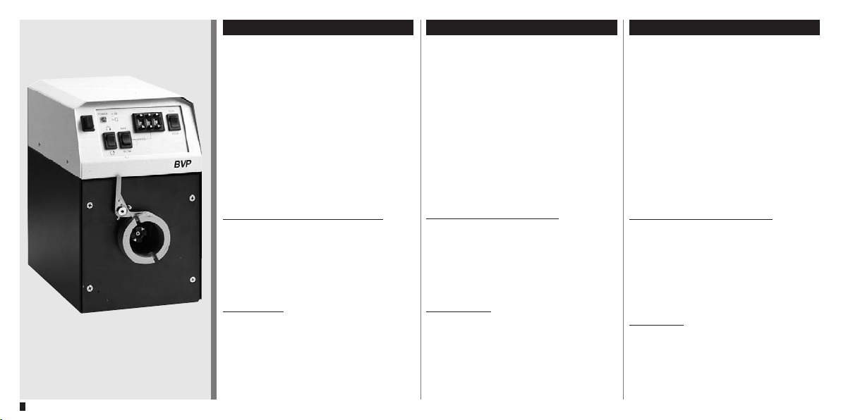
BVP Standard
mit variablem Antrieb
Bestell-Nr. ISM 444
Für Pumpenköpfe:
Pro 280 / Pro 281
Pro 380 / Pro 381
360 / 380 / 380 AD
CA 4 / CA 8 / CA 12
QP Q0 / Q1 / Q2 / Q3
Easy-Load
Standard
Quickload
MS/CA 4-12 / MS/CA 8-6
PTFE Tube 2 mm / 4 mm
SB 2V / 3V
WM 5
Deutsch
12.03.07 CB/GP
BVP Standard
with variable speed drive
Order No. ISM 444
For pump-heads:
Pro 280 / Pro 281
Pro 380 / Pro 381
360 / 380 / 380 AD
CA 4 / CA 8 / CA 12
QP Q0 / Q1 / Q2 / Q3
Easy-Load
Standard
Quickload
MS/CA 4-12 / MS/CA 8-6
PTFE Tube 2 mm / 4 mm
SB 2V / 3V
WM 5
English
Mode d‘emploi
BVP Standard
Moteur à vitesse variable
No. de commande ISM 444
Pour têtes de pompe:
Pro 280 / Pro 281
Pro 380 / Pro 381
360 / 380 / 380 AD
CA 4 / CA 8 / CA 12
QP Q0 / Q1 / Q2 / Q3
Easy-Load
Standard
Quickload
MS/CA 4-12 / MS/CA 8-6
PTFE Tube 2 mm / 4 mm
SB 2V / 3V
WM 5
Français
1

Inhaltsverzeichnis
Contents
Sommaire
Sicherheitsvorkehrungen 4–6
Garantiebestimmungen 7
Produkt 8
Bedienungspanel 9
Geräterückwand 9
Netzspannung 10–11
Spannungswechsel 11
Sicherungswechsel 11
Inbetriebnahme 12–13
Pumpen gegen Druck 14
Ueberlastschutz 15
Wenn die Pumpe ruht 16
Einlaufzeit der Schläuche 17
Lebensdauer der Schläuche 17
Safety precautions 4–6
Warranty terms 7
Product 8
Operating panel 9
Rear panel 9
Mains voltage 10–11
Voltage setting 11
Changing the fuses 11
Starting the pump 12–13
Pumping against back-pressure 14
Overload protection 15
When the pump is not in use 16
Running-in period for tubing 17
Tubing life 17
2
Mesures de précaution 4–6
Conditions de garantie 7
Produit 8
Tableau de commande 9
Tableau arrière 9
Tension d’alimentation 10–11
Commutation de la tension 11
Remplacement des fusibles 11
Mise en marche de la pompe 12–13
Pompage
avec contre-refoulement 14
Protection de surcharge 15
Quand la pompe est hors-service 16
Durée de rodage des tubes 17
Durée de vie des tubes 17
ISMATEC SA/BVP Standard/12.03.07/CB/GP

Inhaltsverzeichnis
Analogschnittstelle 18–20
Contents
Analog interface 18–20
Sommaire
Interface analogique 18–20
ISMATEC SA/BVP Standard/12.03.07/CB/GP
Zubehör 21–23
Pumpenköpfe 24–25
Fließraten pro Kanal
für Mehrkanal-Pumpenköpfe 26–28
Fließraten pro Kanal
für Einkanal-Pumpenköpfe 29–31
Unterhalt 32
Reperaturen 32
Ersatzteile 32
Entsorgung 33
Technische Daten 34
Accessories 21–23
Pump heads 24–25
Flow-rates per channel for
multi channel pump-heads 26–28
Flow-rates per channel for
single-channel pump-heads 29–31
Maintenance 32
Repairs 32
Spare-parts 32
Disposal 33
Technical specifications 34
Accessoires 21–23
Têtes de pompe 24–25
Débits par canal pour têtes
de pompe à multiple canaux 26–28
Débits par canal pour
têtes de pompe à 1 canal 29–31
Entretien 32
Réparation 32
Pièces détachées 32
Mise en rebut 33
Spécifications techniques 34
3

Hinweis
Wir empfehlen, diese Betriebsanleitung
genau durchzulesen.
Beim Betrieb einer Pumpe sind gewisse
Gefahren nicht auszuschliessen.
ISMATEC SA haftet nicht für Schäden,
die durch den Einsatz einer ISMATEC®Pumpe entstehen.
Der Umgang mit Chemikalien liegt nicht im
Verantwortungsbereich der ISMATEC SA.
Please note
We recommend you to read this operating
manual carefully.
When operating a pump, certain hazards
cannot be excluded.
ISMATEC SA does not take liability for
any damage resulting from the use of
an ISMATEC® pump.
ISMATEC SA does not admit responsibility
for the handling of chemicals.
Sicherheitsvorkehrungen
Die ISMATEC® Schlauchpumpen sind
für Förderzwecke im Labor vorgesehen. Wir setzen voraus, dass die
GLP-Richtlinien «Gute Laborpraxis»
sowie die nachstehenden
Empfehlungen befolgt werden.
■ Der Stromkreis zwischen Netz und
Pumpe muss geerdet sein.
■ Die Pumpe darf nur innerhalb der
vorgegebenen Betriebs- und Umgebungsbedingungen betrieben
werden.
■
Stellen Sie die Pumpe nicht näher
als 10 cm an eine Wand und achten
Sie darauf, dass die Belüftungsöffnungen frei sind.
■ Die Pumpe darf nicht eingesetzt
werden:
- für medizinische Anwendungen
am Menschen
- in ex-geschützten Räumen oder
in Gegenwart von entflamm-
baren Gasen und Dämpfen.
Safety precautions
ISMATEC® tubing pumps are designed
for pumping applications in laboratories. As such it is assumed that Good
Laboratory Practice (GLP) and our
following recommendations will be
observed.
■ The circuit between mains supply
and pump has to be earthed.
■ The pump must not be operated
outside the destined operating and
environmental conditions.
■ Place the unit in a well ventilated
position at least 10 cm away from
walls, partitions etc. Ensure that
curtains and similar materials do not
cover the ventilation slits.
■ The pump must not be
used:
- for medical applications on
human beings
- in explosion proof chambers or
in the presence of flammable
gases or fumes.
Mesures de précaution
Les pompes péristaltiques ISMATEC®
sont prévues pour l’usage en laboratoire. Dès lors, nous présumons que
les utilisateurs emploient nos appareils
selon les règles de l’art (normes GLP)
et con-formément à nos recommandations:
■ Le circuit électrique entre le réseau
et la pompe doit avoir été mis à la
terre
■ La pompe ne doit être mise en
opération que dans le cadre des
conditions de fonctionnement et
d’environnement prescrites.
■
Placez la pompe à une distance
d’au moins 10 cm d’une paroi et
veillez à ce que les ouvertures
d’aération ne soient pas bloquées.
■ La pompe ne doit pas être utilisée:
- pour des applications médicales
sur des êtres humains
- dans des locaux protégés contre
les explosions ou en présence de
gaz et vapeurs inflammables.
4
ISMATEC SA/BVP Standard/12.03.07/CB/GP

Remarque
Nous recommandons de lire attentivement
le présent mode d’emploi.
Il n’est pas possible d’exclure certains
risques en cas d’utilisation d’une pompe.
ISMATEC SA décline toute responsabilité pour tout dommage résultant
de l’utilisation d’une pompe ISMATEC®.
ISMATEC SA décline toute responsabilité
pour tout dommage résultant de l’emploi
de produits chimiques.
ISMATEC SA/BVP Standard/12.03.07/CB/GP
Sicherheitsvorkehrungen
■ Kassetten- und Schlauchwechsel
darf nur bei ausgeschalteter Pumpe
ausgeführt werden.
■ Je nach Material und Druckbedin-
gungen haben Pumpenschläuche
eine gewisse Gasdurchlässigkeit und können sich statisch
aufladen. Wir warnen vor möglichen
Gefahren, falls Schläuche in exgeschützte Räume verlegt werden.
■ Falls wegen Schlauchbruchs durch
auslaufende Medien Schäden
verursacht werden können, sind vor
Inbetriebnahme die notwendigen
Sicherheitsvorkehrungen zu treffen.
■ Schlauchpumpen haben rotierende
Teile (Rotor des Pumpenkopfes). Sie
dürfen nur mit komplett eingeklinkten Kassetten bzw. vollständig
geschlossenem Schlauchbett
betrieben werden.
■ Manipulieren Sie nicht am Pumpen-
kopf, bevor die Pumpe ausgeschaltet und vom Netz getrennt ist.
Safety precautions
■ The pump must be switched off
when cassettes or tubing are
inserted or changed.
■ The permeability of pump-tubing
depends on the material used
and pressure conditions. Tubing
can also become electro-statically charged. Please be aware of
possible hazards when laying tubing
in explosion-proof chambers.
■ Tubing can tear and burst during
operation. If this could cause
damage, the necessary safety
measures based on the specific
situation must be taken.
■ Tubing pumps consist of revolving
parts (rotor of the pump-head).
Therefore, the pump must not be
operated before the cassettes are
fully snapped-in or the tube-bed
completely shut.
■ Do not manipulate the pump-head
before the pump is switched off and
disconnected from the mains.
Mesures de précaution
■ La perméabilité des tubes de la
pompe dépend des matériaux
utilisés et des conditions de pression. Les tubes peuvent également
se charger d’électricité statique.
Soyez bien conscients des risques
inhérents à l’installation de tubes
dans des locaux protégés contre les
explosions.
■ En cours d’exploitation, les tubes
peuvent se déchirer ou même
éclater. Si cela pouvait causer
des dommages, il faut prendre les
mesures de sécurité adaptées à la
situation spécifique.
■ Les pompes à tubes sont consti-
tuées de pièces rotatives (rotor de
la tête de pompe). La pompe ne
doit donc pas être mise en service
avant que les cassettes ne soient
entièrement introduites ou avant
que le canal à tube n’ait été entièrement fermé.
■ Ne manipulez jamais la tête de
pompe avant que la pompe n’ait été
mise hors service et déconnectée
du réseau électrique.
5

Sicherheitsvorkehrungen
■ Achten Sie besonders darauf, dass
keine Körperteile wie Finger, Haare,
usw. oder Schmuck sowie lose
Gegenstände wie Kabel, Schläuche,
usw. in den rotierenden Pumpenkopf gelangen.
■ Es dürfen nur neue Sicherungen,
die den Angaben auf Seite 10 entsprechen, verwendet werden.
■ Der Sicherungshalter darf nicht
kurzgeschlossen werden.
■ Das Gehäuse darf während des
Betriebes nicht geöffnet bzw. abgenommen werden.
■ Reparaturen dürfen nur von einer
sich der potentiellen Gefahren
bewussten Fachkraft ausgeführt
werden.
■ Durch Kunden bzw. Drittpersonen
ausgeführte Arbeiten am und im
Gerät erfolgen auf eigene Gefahr.
Safety precautions
■ Be particularly cautious that no
parts of your body such as fingers,
long hair, etc. or jewellery, or loose
objects such as cables or tubing,
etc. can be trapped by the revolving
rotor.
■ Only new fuses, according to the
specifications stated on page 10 in
this manual, must be used.
■ The fuse-holder must not be short-
circuited.
■ Do not open or remove the housing
while the pump is operating.
■ Repairs may only be carried
out by a skilled person who is
aware of the hazard involved.
■ For service and repairs carried out
by the customer or by third-party
companies ISMATEC SA denies any
responsibility.
Mesures de précaution
■ Veillez tout particulièrement à ce
qu’aucune partie de votre corps
comme des doigts, des cheveux
longs, etc. ou encore des bijoux
ou des objets isolés tels que des
câbles ou des tubes ne puissent
être entraînés par le rotor rotatif.
■ N’utilisez que des fusibles neufs
correspondant aux spécifications
indiquées en page 10 du présent
manuel.
■ Le porte-fusible ne doit pas être
court-circuité.
■ N’ouvrez pas et n’enlevez pas le
boîtier pendant que la pompe fonctionne.
■ Les réparations ne doivent être
effectuées que par une personne
connaissant parfaitement les
risques liés à de tels travaux.
■ ISMATEC SA décline toute
responsabilité pour les dommages
découlant de travaux d’entretien et
de réparation assurés par le client
ou par de tierces personnes.
6
ISMATEC SA/BVP Standard/12.03.07/CB/GP

b Garantie
Auf allen von ISMATEC® hergestellten
Erzeugnissen
ab Lieferdatum: 2 Jahre
Übrige Teile, ohne
Verschleißmaterial: 1 Jahr
Wir garantieren eine einwandfreie Funktion
unserer Geräte, sofern diese sachgemäß und
nach den Richtlinien unserer Betriebsanleitung
angeschlossen und bedient werden.
b Warranty
For all parts manufactured by
ISMATEC®
from date of delivery: 2 years
All other parts,
excluding consumables: 1 year
We warrant the perfect functioning of
our products, provided they have been
installed and operated correctly according
to our operating instructions.
b Garantie
Pour toutes les pièces fabriquées par
ISMATEC® à partir de
la date de livraison 2 ans
Autres pièces, sauf
les pièces d’usure 1 an
Nous garantissons un fonctionnement
impeccable de nos appareils sous conditions d’une mise en service compétente et
correspon-dant à nos normes et notices
d’emploi.
ISMATEC SA/BVP Standard/12.03.07/CB/GP
Garantiebestimmungen
Sofern nachweislich Herstell- oder Materialfehler vorliegen, werden die fehlerhaften Teile
nach unserer Wahl kostenlos in Stand gesetzt
oder ersetzt. Die Rücksendung hat in der
Original- oder einer gleichwertigen Verpackung zu erfolgen. Für Pumpenköpfe von
anderen Herstellern als ISMATEC SA gelten
die Garantiebestimmungen des Herstellers.
Durch Inanspruchnahme einer Garantieleistung wird die Garantiezeit nicht beeinflusst.
Weitergehende Forderungen sind ausgeschlossen. Frachtkosten gehen zu Lasten des
Kunden.
Unsere Garantie erlischt, wenn
■ das Gerät unsachgemäß bedient oder
zweckentfremdet wird,
■ am Gerät Eingriffe oder Veränderungen
vorgenommen werden,
■ ein für das Gerät unangemessener Standort
gewählt wird,
■ das Gerät umwelt- und elektrospezifisch
unter Bedingungen eingesetzt wird, für die
es nicht vorgesehen ist,
■ Soft-, Hardware, Zubehör oder Verbrauchs-
material eingesetzt wird, welches nicht
unseren Angaben entsprechen,
■ wegen Schlauchbruchs durch auslaufende
Medien Verunreinigungen entstehen, die zu
Schäden führen.
Warranty Terms
If production or material faults can be proved,
the defective parts will be repaired or replaced
free of charge at our discretion. A defective pump must be returned in the original
ISMATEC® packing or in a packet of equal
quality. For pump-heads from manufacturers
other than ISMATEC SA the warranty terms
of the specific manufacturer are valid. The
duration of the warranty is not affected by
making a claim for warranty service. Further
claims are excluded.
Shipping costs are charged to the customer.
Our warranty becomes invalid in case of
■ improper operation by the user, or if the
pump is diverted from its proper use,
■ unauthorized modification or misuse by the
user or by a third party,
■ improper site preparation and maintenance,
■ operation outside environmental and elec-
trical specifications for the product,
■ use of third-party software, hardware,
interfacing or consumables purchased by
the user and which do not comply with our
specifications,
■ damages caused by contamination or leaks
due to torn or bursted tubing
Garantie
Si un défaut de fabrication ou de matériau
peut être prouvé, les pièces défectueuses
seront réparées ou remplacées gratuitement.
Le renvoi doit être effectué dans l’emballage
d’origine ou similaire. Pour les têtes de pompe
d’autres fabricants qu’ ISMATEC SA, ce sont
les dispositions de garanties du fabricant qui
s’appliquent. La durée de la garantie n’est pas
touchée par le fait que le client demande une
prestation de garantie.
Toute autre prétention est exclue. Les frais
d’expédition sont facturés au client.
Notre garantie n’est plus valable dans les
cas suivants:
■ manipulation inadéquate par l’utilisateur ou
utilisation de la pompe à des fins
auxquelles elle n’est pas destinée,
■ modifications ou emploi non autorisés par
l’utilisateur ou un tiers,
■ préparation et entretien inadéquats de
l’emplacement de la pompe,
■ utilisation de la pompe en dehors de
l’environnement et des spécifications
électriques définies pour le produit,
■ utilisation de matériel, de logiciels,
d’interfaces ou de produits de consommation tiers achetés par l’utilisateur et qui ne
satisfont pas à nos spécifications,
■ dommages causés par encrassement ou
par des fuites en raison de tubes déchirés
ou éclatés
7
Produkt
Packungsinhalt
■ Antrieb BVP
■ Pumpenkopf wie bestellt
■ Netzkabel
■ Betriebsanleitung
Product
Package contents
■ BVP drive
■ Pump head as ordered
■ Power cord
■ Operating instructions
Produit
Emballage
■ Moteur BVP
■
Tête de pompe comme commandé
■ Câble d’alimentation
■ Modes d’emploi
k Die Handhabung des gewählten
Pumpenkopfes finden Sie in der
separat mitgelieferten PumpenkopfBetriebsanleitung.
Überprüfen Sie die Verpackung und
den Inhalt auf Transportschäden.
Finden sich Anzeichen von Beschädigungen, kontaktieren Sie bitte umgehend Ihre ISMATEC®-Vertretung.
Reklamationen können nur innerhalb
von 8 Tagen nach Erhalt der Ware
angenommen werden.
8
k For operating the selected pumphead, please refer to the instruction
manual separately supplied with the
corresponding pump-head.
Please check the package and its
contents for transport damage. If
you find any signs of damage, please
contact your local ISMATEC® representative immediately.
Complaints can only be accepted
within 8 days from receipt of the
goods.
k Vous trouverez la description de
manipulation pour la tête de pompe
commandée dans le mode d’emploi
de la tête de pompe fourni en annexe.
Veuillez contrôler l’emballage et son
contenu et contacter immédiatement
votre représentant ISMATEC® si vous
deviez constater des dommages dus
au transport.
Les réclamations éventuelles ne
seront acceptées qu’au cours
des 8 jours suivant la livraison.
ISMATEC SA/BVP Standard/12.03.07/CB/GP
1
3 42
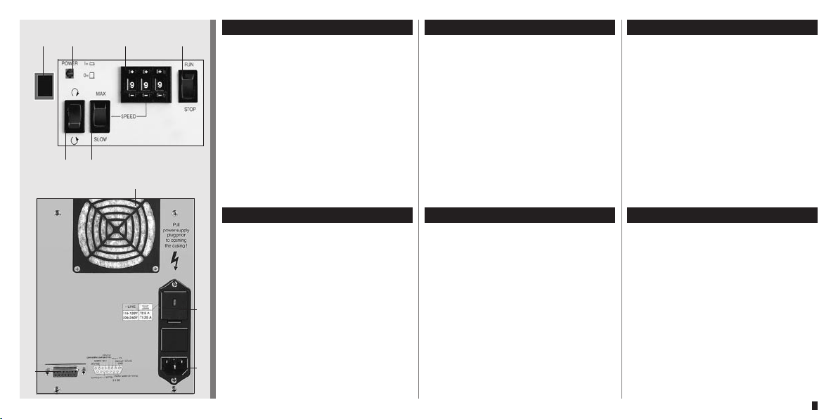
1 Netzschalter
2 Kontroll-Lampe
3 Drehzahlwähler
999 = 240 min–1 (max. Drehzahl)
einstellbar in 0.1% Schritten
Bedienungspanel
Operating panel
1 Mains switch
2 Control light
3 Speed selector
999 = 240 rpm (max. speed)
adjustable in 0.1% steps
Tableau de commande
1 Commutateur principal
2 Lampe de contrôle
3 Sélecteur de vitesse
999 = 240 t/min. (tours max.)
réglable en pas de 0.1 %
4 Marche/Arrêt
4 Start/Stopp
5 Drehrichtung
65
7
6 MAX/SLOW-Taste für Drehzahl
(ideal zum Füllen oder Entleeren
der Schläuche)
4 RUN/STOP
5 Rotation direction
6 MAX/SLOW key for drive speed
(ideal for fast filling or emptying the
system)
5 Sens de rotation
6 Touche MAX/SLOW pour
le nombre de tours
(pour un remplissage et une
vidange rapides du système)
10
ISMATEC SA/BVP Standard/12.03.07/CB/GP
Geräterückwand
7 Lüfter
8 Sicherungshalter mit
Spannungswähler 115 / 230 V
9 Netzbuchse
10 Analogschnittstelle
■ RUN / STOP (TTL)
8
■ Drehrichtung (TTL)
■ Drehzahlsteuerung
0–5 V oder 0–10 V, bzw.
0–20 mA oder 4–20 mA
9
■ Drehzahlausgang 0–10 V
oder 0–12 kHz
Rear panel
7 Ventilator
8 Fuse-holder with voltage
selector 115 / 230 V
9 Mains socket
10 Analog interface
■ RUN / STOP (TTL)
■ Rotation direction (TTL)
■ Speed control
0–5 V and 0–10 V, or
0–20 mA and 4–20 mA
DC
■ Speed output 0–10 V
or 0–12 kHz
DC
Tableau arrière
7 Ventilateur
8 Porte-fusibles avec sélecteur
de tension 115 / 230 V
9 Prise d’alimentation
10 Interface analogique
■ RUN / STOP (TTL)
■ Sens de rotation (TTL)
■ Réglage du nombre de tours
0–5 V ou 0–10 V, resp.
0–20 mA ou 4–20mA
■ Nombre de tours en sortie
0–10 VDC ou 0–12 kHz
9
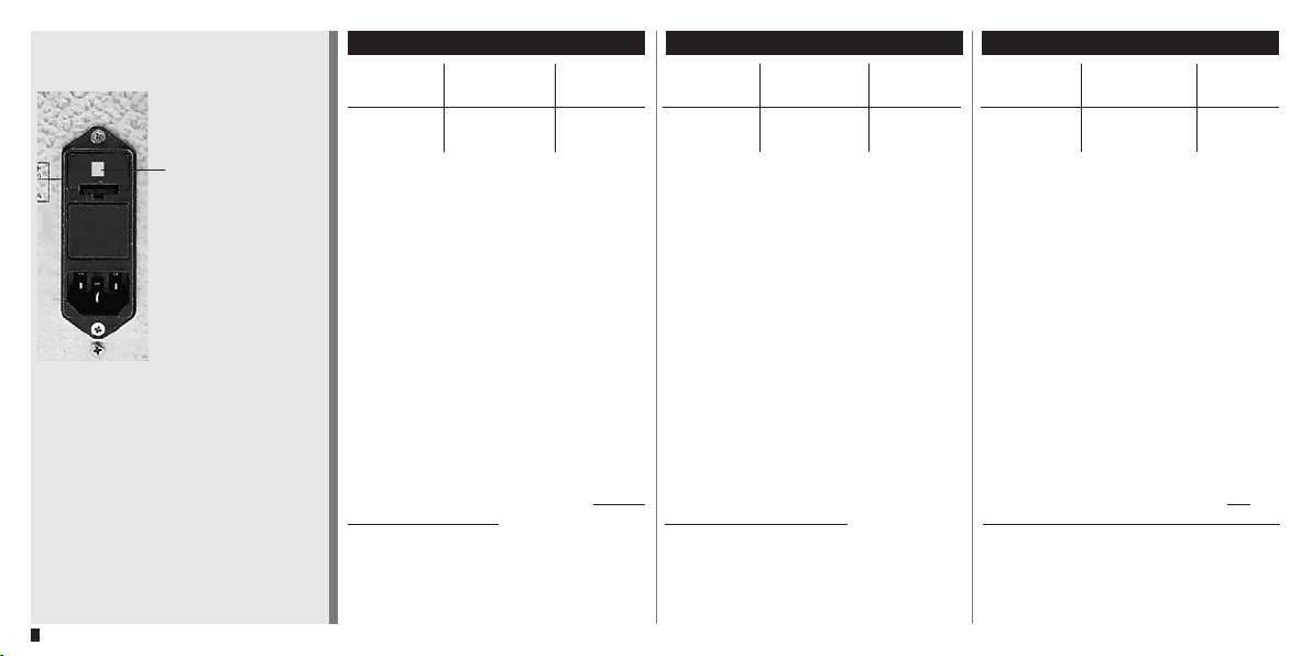
Fenster für Spannungswahlanzeige
Window for voltage
setting
Fenêtre de réglage de
la tension
Netzspannung
Netz- Vor- Sicherung
spannung gabe
220–240 VAC 230 V 50/60 Hz 2 x 1.25 A T
110–120 VAC 115 V 50/60 Hz 2 x 2.50 A T
Vor der Inbetriebnahme
Prüfen Sie, ob die Spannungswahlanzeige im Fenster des Sicherungshalters der Netzspannung Ihres
Landes entspricht.
Mains voltage
Mains Voltage Fuse rating
voltage setting (slow-blow)
220–240 VAC 230V 50/60 Hz 2 x 1.25 A
110–120 VAC 115V 50/60 Hz 2 x 2.50 A
Before starting-up
Check if the voltage setting visible
in the window of the fuse-holder
complies with your local mains
voltage.
Tension d'alimentation
Tension Réglage de Fusibles
d‘alimentation la tension de sécurité
220–240 VAC 230 V 50/60 Hz 2 x 1.25 A*
110–120 VAC 115 V 50/60 Hz 2 x 2.50 A*
*à action retardée
Avant la mise en service
Contrôlez si la tension indiquée dans la
fenêtre du porte-fusibles correspond à la
tension de votre réseau local.
10
Wenn nötig, muss die Einstellung
geändert und die 2 Sicherungen
ausgetauscht werden.
Steckdose/Netzkabel
Verwenden Sie ausschließlich das
mitgelieferte Originalkabel. Die Steckdose muss geerdet sein. (Schutzleiterkontakt)
If necessary, the voltage setting must
be changed and the 2 fuses must be
replaced.
Socket/Power cord
Use exclusively the original power
cord supplied with the pump. The
socket must be earthed (protective
conductor contact).
Si nécessaire, modifiez la tension et
remplacez les deux fusibles correspondants.
Prise/câble d’alimentation
N’utilisez que le câble d’alimentation
d’origine fourni avec la pompe. La
prise doit avoir été raccordée à la terre
(contact conducteur de protection).
ISMATEC SA/BVP Standard/12.03.07/CB/GP
2
k
4
1
3
230 V: 2 x 1.25 A T
115 V: 2 x 2.50 A T
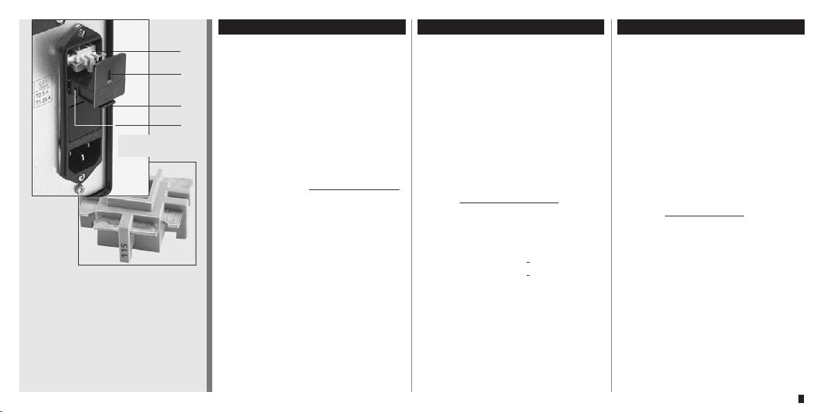
2
1 Sicherungshalter / Fuse-holder
Porte-fusibles
2 Spannungswahl-Plättchen
Voltage selector plate
Plaquette de sélection de la tension
3 Position der 2 Sicherungen
Location of the 2 fuses
Position des 2 fusibles
4 Fenster im Sicherungshalter
Window in the fuse-holder
Fenêtre sur le porte-fusibles
ISMATEC SA/BVP Standard/12.03.07/CB/GP
k
Netzspannung
Spannungsumschaltung 115V/230V
und Sicherungen auswechseln
k Pumpe ausschalten,
Netzstecker ausziehen.
1 Sicherungsschublade mit einem
kleinen Schraubenzieher (Gr. 0)
öffnen und herausziehen.
2 Spannungswahl-Plättchen heraus-
nehmen und mit gewünschtem
Spannungswert gegen das Fenster
im Sicherungshalter gerichtet
wieder einrasten.
3 2 neue Sicherungen einsetzen
k230 V: 2 x 1.25 A T
k115 V: 2 x 2.50 A T
Immer 2 Sicherungen (träge)
vom selben Typ, entsprechend der
ortsüblichen Netzspannung,
einsetzen. Bei defekter Sicherung
immer beide austauschen.
4 Sicherungsschublade schließen.
Spannungswert ist im Fenster
sichtbar.
Mains voltage
Voltage setting
and changing the fuses
k Switch the pump off,
pull out the mains plug.
1
Pull out the fuse-holder by opening
it with a small screw-driver (size 0).
2 Take out the voltage selector plate.
Turn it and re-insert it into the fuseholder so that the required voltage
rating is facing the window of the
fuse-holder.
3 Insert 2 new fuses
k230 V: 2 x 1.25 A (slow-blow)
k115 V: 2 x 2.50 A (slow-blow)
Use always 2 slow-blow fuses
of the same type complying with
the local mains voltage. In case of a
defective fuse, always replace both.
4 Shut the fuse-holder. The voltage
rating is visible in the window.
115V / 230V
Tension d'alimentation
Commutation de la tension
et remplacement des fusibles
k Eteindre la pompe. Déconnecter le
câble d’alimentation
1 Extraire le porte-fusible en ouvrant la
pince supérieure et inférieure par exemple avec un tournevis de la taille 0.
2 Extraire la plaquette de sélection de
la tension. La tourner et la réinsérer
dans le porte-fusibles de manière à ce
que la valeur de tension souhaitée soit
dirigée contre la fenêtre du portefusibles.
3 Insérer deux nouveaux fusibles
k230 V: 2 x 1.25 A (retard)
k115 V: 2 x 2.50 A (retard)
N’employer toujours que deux
fusibles (à action retardée) correspondant à la tension du circuit local.
Lorsqu‘un fusible est défectueux,
toujours changer les deux fusibles.
4 Fermer le porte-fusibles. La valeur
de tension est visible dans la
fenêtre.
115V/230V
11

Inbetriebnahme
■
Netzspannung im Fenster des
Sicherungshalters (Geräterückseite)
kontrollieren.
Allenfalls anpassen, wie auf
Seite 10–11 beschrieben.
■ Pumpenkopf gemäß separater
Kopfanleitung montieren.
Starting the pump
■ Check the voltage rating in the
window of the fuse-holder (on rear
panel).
If necessary, change the rating as
indicated on page 10–11.
■
Mount the pump-head according to
the instruction manual supplied with
the pump-head.
Mise en marche
■ Contrôler la tension indiquée dans
la fenêtre du porte-fusibles
(derrière l’appareil).
Si nécessaire, modifier la tension
(voir page 10-11)
■ Installer la tête de pompe selon le
manuel d’utilisation fourni avec la
tête de pompe.
12
■ Bei FMI-Pumpenköpfen den
Winkel für das Kolbenhubvolumen
einstellen.
■ Bei Peristaltikpumpen Pumpen-
schlauch einsetzen.
■ Pumpenschlauch am System
anschließen.
■ Pumpe am Netz anschließen.
■ Insert the tubing into the peristaltic
pump-head.
■ If using an FMI piston pump-head,
adjust the angle for the piston
stroke volume.
■ Connect the pump tubing to the
system.
■ Connect the pump to the mains.
■ Pour les pompes péristaltiques,
introduire le tube de pompe.
■ Pour les têtes de pompe FMI, régler
l’angle du volume du coup de
piston.
■ Connecter le tube de la pompe au
système.
■ Raccorder la pompe au réseau et la
mettre en service.
ISMATEC SA/BVP Standard/12.03.07/CB/GP

Inbetriebnahme
1 Netzschalter ein, Kontroll-Lampe
leuchtet.
1
1
2 5
2 Am Digipot die gewünschte Dreh-
zahl einstellen.
(999 = 240 min–1)
k Die Drehzahl kann auch bei
laufender Pumpe verändert werden.
Starting the pump
1 Press in the mains switch, the
control light is on.
2 Set the required speed on the
3-digit speed selector.
(999 = 240 rpm)
k The rotation speed can be
adjusted while the pump
is running.
Mise en marche
1 Interrupteur de réseau en marche,
la lampe de contrôle s’illumine.
2 Régler le nombre de tours souhaité
sur le Digipot
(999 = 240 t/min.)
k Le nombre de tours peut
également être modifié en cours
d’exploitation.
4
3
ISMATEC SA/BVP Standard/12.03.07/CB/GP
3 Drehrichtung wählen
k Drehrichtung darf nur bei
stehendem Antrieb geändert
werden.
4 Bei laufender Pumpe ermög-
licht die MAX/SLOW-Taste das
schnelle Füllen (oder Entleeren) des
Pumpenschlauches.
5 Pumpe mit RUN/STOP-Taste
starten.
3 Choose the rotation direction
k Never change the rotation
direction while the pump is running.
4 The MAX/SLOW- button allows
rapid filling (or emptying) of the
tubes while the pump is running.
5 Start the pump by switching the
RUN/STOP button.
3 Sélectionner le sens de rotation.
k Le sens de rotation ne doit être
modifié que lorsque la pompe n’est
pas en opération.
4 La touche MAX/SLOW permet un
remplissage/une vidange rapide du
tuyau de la pompe.
5 Mettre la pompe en marche avec
RUN/STOP.
13

Pumpen gegen Druck
Die BVP kann im Dauerbetrieb bis
max. 1.5 bar Differenzdruck eingesetzt werden. Je nach Pumpenkopf
und Schlauchdurchmesser (kleinere
Durchmesser) kann kurzzeitig auch
gegen einen höheren Druck gepumpt
werden.
Pumping against pressure
The BVP can be used for continuous
duty at a differential pressure of max.
1.5 bar. For short-time operation
higher differential pressures may be
managed depending on the mounted
pump-head and tubing i.d. (smaller
i.d. is preferable).
Pompage contre pression
En exploitation continue, le moteur
BVP peut être employée jusqu’à
1,5 bar de pression différentielle au
maximum. Suivant la tête de pompe et
le diamètre du tube (petits diamètres)
choisis, il est également possible de
pomper brièvement contre des pressions plus fortes.
14
Die FMI-Pumpenköpfe können je
nach Anwendungsbedingungen bis
zu einem Differenzdruck von 7 bar
eingesetzt werden.
Im Zweifelsfalle wenden Sie sich bitte
an Ihre ISMATEC®-Vertretung.
Depending on the application conditions the FMI pump-heads allow
operations at differential pressures of
up to 7 bar.
In case of any doubts please contact
your ISMATEC® agent.
Les têtes de pompe FMI peuvent
être employées jusqu’à une pression
différentielle de 7 bars en fonction des
conditions d’application.
En cas de doute, veuillez vous
adresser à votre représentant
ISMATEC®.
ISMATEC SA/BVP Standard/12.03.07/CB/GP

Überlastschutz
Die Pumpe BVP Standard besitzt eine
Überlast-Sicherung.
Overcurrent protector
The tubing pump BVP Standard
features an overload protector.
Protection en cas de surcharge
La pompe BVP Standard possède une
protection de surcharge.
ISMATEC SA/BVP Standard/12.03.07/CB/GP
Bei aktiviertem Überlastschutz stoppt
die Pumpe und die Kontroll-Lampe
blinkt (siehe auch Beschreibung von
Pin 12 der Analogschnittstelle auf
Seite 19).
In einer solchen Situation ist die
Pumpe sofort mit dem Netzschalter auszuschalten.
k
Abkühlen lassen (es dauert ca.
2 Min., bis die Pumpe wieder betriebsbereit ist).
Bevor die Pumpe wieder gestartet
wird, ist unbedingt zu prüfen, was die
Überlastung der Pumpe verursacht
hat (z.B. zu hoher Differenzdruck).
k
Erst nachdem die Ursache für die
Überlast behoben worden ist, darf die
Pumpe neu gestartet werden.
When the overcurrent protector is
activated, the pump is stopped and
the control light flashes (see also the
description of pin 12 of the analog
interface on page 19).
Whenever this situation occurs, the
pump must be switched off immediately.
k
Let the pump cool down (it takes
about 2 minutes until the pump is
ready again)
Before the pump is re-started, it is
most important to check the reason
for the overload (eg. too high differential pressure).
k
Only when the cause of the overload has been detected and the failure
corrected accordingly may the pump
be started again.
Lorsque la protection de surcharge
est activée, la pompe s‘arrête et la
lampe de contrôle clignote (voir aussi
la description du pin 12 de l‘interface
analogique en page 19).
Dans une telle situation, la pompe doit
étre immédiatement déclenchée.
k
Laisser refroidir (la pompe est à
nouveau prête à fonctionner après
environ 2 min).
Avant d’enclencher à nouveau la
pompe, il est indispensable de
contrôler ce qui a pu provoquer la
surcharge (p. ex. pression différentielle
trop élevée).
k
La pompe ne doit être remise en
marche qu‘après l‘identification de la
cause de la surcharge et la réparation
correspondante du défaut.
15

k
Wenn die Pumpe ruht
Wir empfehlen, bei Betriebsunterbrüchen die Schläuche zu entspannen
bzw. aus dem Pumpenkopf zu
entfernen.
Sie schonen damit die Schläuche und
verlängern ihre Lebensdauer.
When the pump is not in use
When the pump is idle, we
recommend you to release the tubing
from pressure.
This helps to protect the tubing from
unnecessary strain and prolongs its
service-life.
Durant les temps d‘arrêt
En cas d’interruption de l’exploitation,
nous recommandons de détendre les
tubes, respectivement de les sortir de
la tête de pompe.
Vous ménagez ainsi les tubes et en
prolongez la durée de vie.
k
16
Rückflussgefahr
a
b
Wird der Schlauch nicht mehr
gequetscht, kann das Medium zurückfließen (Syphon-Effekt).
a Beim Einsatz von Kassetten muss
der Schlauch nicht herausgenom–
men werden. Es genügt, wenn die
Kassette auf einer Seite
ausgeklinkt wird.
b Bei den einkanaligen Pumpen-
köpfen 360, 380 und Easy Load
kann zur Schlauchentspannung das
Schlauchbett geöffnet werden.
Syphoning effect
When the tubing is released from
squeezing, the fluid can flow back to
the reservoir.
a Tubing used with cassettes do not
need to be removed. Releasing the
cassette on one side is sufficient.
b The single-channel pump-heads
360, 380 and Easy Load allow
opening the tube-bed in order to
release the tubing pressure.
Danger de refluement.
Si le tube n’est plus pincé, le liquide
refoulé peut refluer.
a Lors de l’emploi de cassettes, il
n’est pas nécessaire d’extraire le
tube. Il suffit de relâcher la cassette
sur l’un des côtés.
b Sur les têtes de pompe monocanal
360, 380 et Easy Load, l’espacetube peut être ouvert pour détendre
les tubes.
ISMATEC SA/BVP Standard/12.03.07/CB/GP

Hinweis
Wir verweisen auf unsere ausführliche
Schlauchdokumentation.
Please note
Please refer to our detailed tubing documentation.
Remarque
Veuillez vous référer à notre documentation détaillée sur les tubes.
ISMATEC SA/BVP Standard/12.03.07/CB/GP
Einlaufzeit der Schläuche
Jeder neue Schlauch braucht eine
Einlaufzeit. Für konstante und reproduzierbare Fließraten ist es unbedingt
nötig, neue Schläuche vor ihrem
Einsatz mind. 1–3 Stunden mit Wasser
oder dem zu fördernden Medium
einlaufen zu lassen.
Lebensdauer der Schläuche
Die Lebensdauer hängt stark von den
jeweiligen Anwendungsbedingungen
in Kombination mit dem verwendeten
Schlauchmaterial ab.
Beispiel: Chemikalien, Drehzahl, Differenzdruck, Temperatur,
Viskosität, Schlauchanpressdruck, etc.
Unverbindliche Richtwerte über die
Lebensdauer finden Sie in unserem
ISMATEC®-Katalog.
Zur Verbesserung der Gleitfähigkeit
und Förderung der Lebensdauer
empfehlen wir, die Schläuche und
Pumpenrollen von Zeit zu Zeit mit
Silikonölspray (Best.Nr. SC0179)
einzusprühen.
Running-in period for tubing
Every new tube requires a running-in
period. If constant and reproducible
flow rates are required, we recommend you to run new tubing in with
water or the medium to be pumped
for at least 1 to 3 hours before you
start the application.
Tubing life
The service-life of the tubing depends
on the application and the tubing
material used.
Example: chemicals, rotation speed,
differential pressure, temperature,
viscosity, pressure on tubing, etc.
General information on the servicelife is stated in our ISMATEC® catalog
(without obligation!).
In order to improve the lubrication and
service-life of the tubing, we recommend users to spray both the tubing
and the pump rollers with our silicone
oil spray (Order No. SC0179).
Durée de rodage des tubes
Chaque nouveau tube a besoin d’un
temps de rodage. Pour obtenir des
débits constants et reproductibles, il
est absolument nécessaire de roder
de nouveaux tubes avant leur utilisation pendant 1 à 3 heures au minimum
avec de l’eau ou avec le liquide à
refouler.
Durée de vie des tubes
La durée de vie dépend fortement
des conditions d’application en
combinaison avec le matériau du
tube employé. Exemple: produits
chimiques, nombre de tours, pression
différentielle, température, viscosité,
pression du tube, etc.
Vous trouverez des valeurs de référence indiquées sans engagement
de notre part dans notre catalogue
ISMATEC®.
Pour améliorer le débit et accroître la
durée de vie des tubes, nous recommandons de vaporiser les tubes et
les galets de pompe de temps à autre
avec de l’huile de silicone en spray
(No de commande SC0179)
17

direction start
DC
internal speed speed OUT
overload
(idle)
15-polige Buchse
der Analogschnittstelle
15-pin socket
of analog interface
Douille à 15 pôles
de l‘interface analogique
TTL-Kontakte / TTL contacts
Drehrichtung/Rotation direction
Sens de rotation
Eingang / Input / Entrée
0–5V / 0–10V
0–20mA / 4–20mA
Drehzahl / Speed / Nombre de tours
Ausgang / Output / Sortie
0–10 VDC/0–12 kHz
Drehzahl / Speed / Nombre de tours
remotespeed IN
+5 V
RUN/STOP
18
Analogschnittstelle
Pin 1, (GND) Masse
GND+36 V
DC
Bezugspotential für alle anderen
Eingänge.
Pin 2, remote
Umschaltung zwischen manueller
Bedienung und der Analogschnittstelle. Zur Aktivierung der AnalogSchnittstelle muss Pin 2 mit Pin 1
(Masse) verbunden werden.
Pin 3, start
Im Remote-Betrieb (Pin 2 auf GND)
startet die Pumpe bei Verbindung mit
Pin 1 (GND)
Pin 4, direction
Wenn offen, dreht die Pumpe im
Gegenuhrzeigersinn; wenn mit Pin 1
(GND) verbunden, dreht sie im Uhrzeigersinn.
Pin 5, speed IN
Externe Drehzahlsteuerung
(0–5V, 0–10V, 0–20mA, 4–20mA)
Eingangsimpedanz und Wahlmöglichkeiten mittels DIP-Switch im Geräteinnern (siehe Seite 20).
Analog interface
Pin 1, (GND) Ground
Reference potential for all other
inputs.
Pin 3, start
In remote operation (pin 2 to GND) the
pump starts when connected to pin
1 (GND)
Pin 4, direction
In the open position the pump turns
counter-clockwise; when connected
to pin 1 (GND) it turns clockwise.
Pin 4, direction
If this pin is left open, the pump runs
in clockwise direction. Connecting
pin 4 to the ground (pin1) makes
the pump run in counter-clockwise
direction.
Pin 5, speed IN
External speed control
(0–5V, 0–10V, 0–20mA, 4–20mA)
Input impedance and input range can
be selected via a dip-switch inside the
pump (see page 20).
Interface analogique
Pin 1, (GND) Terre
Potentiel de référence pour toutes les
autres entrées
Pin 3, start
En exploitation à distance (pin 2 sur
GND), la pompe se met en route dès
qu’elle est connectée au pin 1 (GND)
Pin 4, direction
Si ouvert, le sens de rotation de la
pompe est celui contraire des aiguilles
d’une montre.; si relié avec le pin 1
(GND), elle tourne dans le sens des
aiguilles d’une montre.
Pin 4, direction
A entrée non reliée, la pompe tourne
dans le sens des aiguilles d’une montre.
Lorsque cette entrée est reliée à la terre
(Pin 1), la pompe tourne dans le sens
contraire
Pin 5, speed IN
Réglage externe du nombre de tours
(0–5V, 0–10V, 0–20mA, 4–20mA )
Impédance d‘entrée et réglage de
zone au moyen de l’interrupteur DIP à
l’intérieur de l’appareil (c.f. page 20).
.
ISMATEC SA/BVP Standard/12.03.07/CB/GP

direction start
DC
internal speed speed OUT
overload
(idle)
15-polige Buchse
der Analogschnittstelle
15-pin socket
of analog interface
Douille à 15 pôles
de l‘interface analogique
TTL-Kontakte / TTL contacts
Drehrichtung/Rotation direction
Sens de rotation
Eingang / Input / Entrée
0–5V / 0–10V
0–20mA / 4–20mA
Drehzahl / Speed / Nombre de tours
Ausgang / Output / Sortie
0–10 VDC/0–12 kHz
Drehzahl / Speed / Nombre de tours
ISMATEC SA/BVP Standard/12.03.07/CB/GP
RUN/STOP
remotespeed IN
+5 V
GND+36 V
DC
Analogschnittstelle
Pin 7, +36 V
Ca. +36 VDC stehen unstabilisiert zur
Verfügung (max. Belastung 1 A)
Pin 9, speed OUT
Die werkseitige Einstellung ist
0–10 VDC, proportional zur Motordrehzahl 2.4–240 min–1. Alternativ steht
ein Frequenzbereich von 0–12 kHz
zur Verfügung. Wahleinstellung mittels
DIP-Switch im Geräteinnern (siehe
Seite 20).
Pin 10, +5V
Ist mit der stabilisierten +5VDC Versorgungsspannung der Pumpe verbunden.
Pin 12, idle, overload
Bei laufender Pumpe liegen an diesem
Pin +5V
Überlast wechselt die Spannung auf
0VDC.
k Netzspannung ausschalten und
2 Min. abkühlen lassen.
Pin 13, internal speed
Verbindet man Pin 13 mit Pin 1
(Masse), kann die Drehzahl mit dem
Drehzahlwähler im Bedienungspanel
anstelle des Signals an Pin 5 eingestellt werden.
DC
DC
an. Im Stillstand oder bei
DC
Analog interface
Pin 7, +36 V
About +36 VDC (unstabilised) are
available the pump motor
(max. load 1 A).
Pin 9, speed OUT
The default setting is 0–10 VDC, proportionally to the motor speed 2.4–240
rpm. Alternatively a frequency range
from 0 to 12 kHz is available. The input
range can be selected via a dip-switch
inside the pump (see page 20).
Pin 10, +5VDC
This pin is connected to the stabilised
+5VDC voltage supply of the pump.
Pin 12, idle, overload
This pin is at
runs. When idle or in overload, the
voltage changes to +5V
k Switch off the mains voltage and let
the device cool down for 2 minutes.
Pin 13, internal speed
If pin 13 is connected with pin 1
(ground), the pump speed can be
adjusted via the speed selector on the
operating panel instead of using the
signal at pin 5.
DC
+5V
while the pump
DC
.
DC
Interface analogique
Pin 7, +36 V
Environ +36 VCC sous forme non
stabilisée sont à la disposition du moteur
de pompe (courant max. 1 A).
Pin 9, speed OUT
Le réglage en usine est de 0–10 V CC
et proportionnel au nombre de tours du
moteur de 2.4–240 t/min. Une marge de
fréquence de 0–12 kHz est à disposition
comme alternative0. Réglage de zone au
moyen de l’interrupteur DIP à l’intérieur
de l’appareil (c.f. page 20).
Pin 10, +5VAC
Ce pin est connecté à la tension d’alimentation stabilisée de +5VCC de la pompe.
Pin 12, idle, overload
Lorsque la pompe fonctionne, ce pin est
à +5V
ou en surcharge, la tension change à 0V
k Eteindre la tension de réseau et
laisser refroidir pendant 2 minutes.
Pin 13, internal speed
Si le pin 13 est relié au pin 1 (terre), le
nombre de tours pourra être réglé au
moyen du sélecteur du nombre de tours
sur le panneau de manipulation en lieu et
place du signal sur le pin 5.
AC
. Lorsque la pompe est en veille
AC
.
AC
19

Imp.Pins
1hctiwS-PID
2hctiwS-PID
3hctiwS-PID
4hctiwS-PID
5hctiwS-PID
6hctiwS-PID
5niP
NIdeeps
V5–0
*NO
*FFO
*FFO
*FFO
*FFO
*NO
V01–0
FFO
NO
FFO
FFO
FFO
NO
Am02–0
FFO
FFO
NO
FFO
NO
NO
Am02–4
FFO
FFO
FFO
NO
NO
FFO
Eingang
Input/ Entrée
DIP-Switch
S2
P2
S1
P1
A
k
B
Pin 9 Ausgang/Output/Sortie
A = 0–10 VDC (Standard)
B = 0–12 kHz
Einstellungen Schalter S1 Settings of switch S1 Réglages du switch S1
100kΩ
20kΩ
250Ω
250Ω
* Default-Einstellung * Default setting
Schiebeschalter S2
Dieser Schalter beeinflusst Pin 9,
speed OUT
Stellung A: 0–10 VDC (Standard)
Stellung B: 0–12 kHz
k Vergewissern Sie sich, dass die
Pumpe vom Netz getrennt ist.
Sliding switch S2
This switch affects Pin 9,
speed OUT
Position A: 0–10 VDC (Standard)
Position B: 0–12 kHz
k Make sure that the pump is
disconnected from the mains
supply.
* Valeurs par défaut
Switch coulissant S2
Cet interrupteur influence le pin 9,
speed OUT
Position A: 0-10 VDC (standard)
Position B: 0-12 kHz
k Assurez-vous que la pompe soit
déconnectée du réseau.
Das Gerät darf nur von einer
20
Fachkraft geöffnet werden!
Spannungsführende Teile im Innern des
Gerätes können auch längere Zeit nach
Ziehen des Netzsteckers noch unter
Spannung stehen.
The instrument should only be
opened by a qualified technician!
Capacitors inside the pump may still
be charged even though the mains
plug has been disconnected some
time ago.
un spécialiste uniquement!
Des pièces conductrices peuvent
encore être sous tension très
longtemps après que le câble ait été
débranché de la prise.
ISMATEC SA/BVP Standard/12.03.07/CB/GP
Cet appareil doit être ouvert par

Zubehör
Fußschalter
Bestell-Nr. IS 10039
Dieser Fußschalter dient als Impulgeber zum Starten bzw. Anhalten der
Pumpe. Er ist sehr nützlich, wenn die
Pumpe als Dosiergerät zum Abfüllen
von Röhrchen, Gläsern, Flaschen usw.
eingesetzt wird. Beide Hände bleiben
für das Arbeiten mit Flaschen, usw.
frei.
Accessories
Foot switch
Order No. IS 10039
This foot switch serves as a start/stop
device. It is very useful when using the
pump as a dispenser for filling tubes,
bottles, etc.. Both hands are free for
handling the bottles and tubing.
Accessoires
Pédale de commande
No de commande IS 10039
Cette pédale de commande est
utilisée pour enclencher et déclencher
la pompe. Elle est très utile lorsque la
pompe est utilisée comme appareil de
dosage pour remplir des tubes, des
flacons, etc. Les deux mains sont ainsi
libres pour travailler.
ISMATEC SA/BVP Standard/12.03.07/CB/GP
21

Zubehör
Ersatz-Kassetten aus POM
Accessories
Spare-cassettes in POM
Accessoires
Cassettes de rechange en POM
MS/CA Click‘n‘go Kassette
MS/CA Click‘n‘go cassette
CA Click‘n‘go Kassette
CA Click‘n‘go cassette
Adapter für CA-Kassette
Adaptor for CA cassette
Adaptateur pour cassette CA
22
MS/CA Click‘n‘go
Bestell-Nr. IS 3510
MS/CA Anpresshebel*
Bestell-Nr. IS 0649
CA Click‘n‘go
Bestell-Nr. IS 3710
CA Anpresshebel*
Bestell-Nr. IS 0122
Adapter für Typ CA IS 0123
(pro Kassette 2 Stk. bestellen)
Click'n'go-Kassetten
Beim Einsatz von neuen Schläuchen kann es
vorkommen, dass je nach verwendetem
Schlauch (Härte und Durchmesser) die Pumpe
anfänglich nicht fördert. Trifft dies zu, so
empfehlen wir, die Schläuche zu benetzen und
die Pumpe zuerst mit eingesetztem Schlauch
ca. 15–30 Minuten laufen zu lassen.
MS/CA Click‘n‘go
Order No. IS 3510
MS/CA pressure lever*
Order No. IS 0649
CA Click‘n‘go
Order No. IS 3710
CA pressure lever*
Order No. IS 0122
Adaptor for type CA IS 0123
(order 2 adaptors per cassette)
Click'n'go-Cassettes
When using new tubing for the first time, it
may occur that, depending on the tubing used
(hardness and diameter), the pump cannot be
primed and, hence, does not deliver the liquid.
If that is the case we recommend you to prime
the tubing and to run the pump with the tubing
inserted for about 15 to 30 minutes.
MS/CA Click‘n‘go
No de commande IS 3510
MS/CA levier de pression*
No de commande IS 0649
CA Click‘n‘go cassette
No de commande IS 3710
CA levier de pression*
No de commande IS 0122
Adaptateur pour CA IS 0123
(2 adaptateur par cassette)
Cassettes Click'n'go
Lors de la première utilisation de nouveaux tubes, il se peut, suivant le tube utilisé (dureté et
diamètre), que l’amor-çage du tube ne se fasse
pas correctement et que de ce fait aucun liquide
ne soit délivré. Si tel est le cas, nous conseillons
de remplir les tubes et de faire fonctionner la
pompe avec tube inséré pendant 15 à 30 minutes.
ISMATEC SA/BVP Standard/12.03.07/CB/GP

ISMATEC SA/BVP Standard/12.03.07/CB/GP
Zubehör
Ersatz-Kassetten aus PVDF
MS/CA Anpresshebel*
Bestell-Nr. IS 3629
CA Anpresshebel*
Bestell-Nr. IS 3820
* Die Kassetten mit Anpresshebel
sind als Option lieferbar.
Je nach Anwendung können sie bei
höherem Differenzdruck geeigneter
sein.
Material POM-C
Polyoxymethylen-Copolymer
– gute chemische Beständigkeit gegenüber vielen
organischen Lösungsmitteln und starken Basen
– wird von starken Säuren und oxidierenden
Substanzen angegriffen
– UV-stabilisiert und bis 80°C temperaturbeständig
(trocken, langzeitig) oder 136°C (trocken, kurzzeitig)
Matrial PVDF
Polyvinylidenfluorid
– sehr gute chemische Beständigkeit gegenüber
Säuren sowie den meisten aliphatischen, aroma tischen und chlorierten Lösungsmitteln
– ungeeignet für längeren Kontakt mit Estern,
Ketonen, Aminen und starken Basen
– stabil gegenüber UV-Strahlen und bis 110°C
temperaturabeständig (trocken, langzeitig) oder
142°C (trocken, kurzzeitig)
Accessories
Spare-cassettes in PVDF
MS/CA pressure lever*
Order No. IS 3629
CA pressure lever*
Order No. IS 3820
* The cassettes with pressure lever
are available on request. Depending on the application, this type of
cassette may provide better results
at elevated differential pressure
conditions.
Materials POM-C
Polyoxymethylene-Copolymer
– good chemical resistance to many organic
solvents and strong alkaline chemicals
– is affected by strong acids and oxidizing
substances
– UV-stabilized and stable up to temperatures of
80°C/176°F (dry, continuous use) or 136°C/277°F
(dry, for a short time)
Materials PVDF
Polyvinylidene fluoride
– very good chemical resistance to acids and most
aliphatic, aromatic and chlorinated solvents
– not suitable for long contact with esters, ketones,
amines and strong alkaline chemicals
– stable both to UV radiation and temperatures up
to 110°C/230°F (continuous use) or 142°C/288°F
(for a short time)
Accessoires
Cassettes de rechange en PVDF
MS/CA levier de pression*
No de commande IS 3629
CA levier de pression*
No de commande IS 3820
* Les cassettes avec levier de pres-
sion sont disponibles sur demande.
Selon l’application, ce type de
cassette peut produire de meilleurs
résultats sous des conditions de
pression différen-tielle supérieure.
Matériau POM-C
Copolymère de polyoxyméthylène
– bonne résistance chimique à de nombreux solvants
organiques et produits chimiques fortement alcalins
– affecté par les acides forts et les substances
oxydantes
– stabilisé aux UV et stable jusqu'à des tempéra tures de 80°C/176°F (marche à sec, continue) ou
136°C/277°F (marche à sec, pour une courte durée)
Matériau PVDF
Fluorure de polyvinylidène
– trés bonne résistance chimique aux acides et à la
plupart des solvants aliphatiques, aromatiques et
chlorés
– ne convient pas à un long contact avec les esters,
cétones, amines et produits chimiques très alcalins
– stable aux rayonnements UV et aux températures
jusque'à 110°F/230°F (utilisation continue) ou
142°C/288°F (pour une courte durée)
23

Montage
Jedem Pumpenkopf liegt eine Montageanleitung bei.
Für die passenden Pumpenschläuche
verweisen wir auf unsere ausführliche
Schlauch-Dokumentation.
Mounting
Each pump-head is supplied with an
instruction manual.
For selecting the correct tubing,
please refer to our detailed tubing documentation.
Montage
Chaque tête de pompe est livrée avec un
manuel d’instructions pour le montage.
Pour le choix de tubes adéquats, veuillez
vous référer à notre documen-tation
détaillée sur les tubes de pompe.
Auswechselbare
Pumpenköpfe
Diese auswechselbaren Pumpenköpfe können auch einzeln bestellt
und am Antrieb BVP montiert werden.
0.17–880
ml/min
360
ISM 719
1.2–3700
ml/min
Pro 280
ISM 785
8.7–3100
ml/min
Pro 281
ISM 793
0.16–1100
Easy-Load
MF 0313/738
0.58–1000
Easy-Load II
MF 0446/738
ml/min
ml/min
Interchangeable
Pump-heads
These interchangeable pump-heads
can also be ordered separately and
mounted on the BVP drive.
1.1–2800
ml/min
380
ISM 718
1.1–3400
ml/min
Pro 380
ISM 791
8.0–2900
ml/min
Pro 381
ISM 797
0.57–57
ml/min
Standard 1.6
5.6–560
ml/min
Standard 6.4
8.2–820
ml/min
Standard 8.0
Têtes de pompe
interchangeables
Ces têtes de pompe interchangeables peuvent également être
commandées séparément et montées
sur le moteur BVP.
0.99–3600
380 AD
ISM 725
3.6–2300
WM 5
ISM 722
0.14–910
Quickload 1.6
MF 0136/723
3.7–590
Quickload 2.4
MF 0137/723
ml/min
ml/min
ml/min
ml/min
24
ISMATEC SA/BVP Standard/12.03.07/CB/GP

Standard-Schläuche
Standard tubing
Tubes au mètre
2-Stopper-Schläuche
2-stop collared tubing
Tubes à 2 arrêts
3-Stopper-Schläuche
3-stop collared tubing
Tubes à 3 arrêts
Auswechselbare
Pumpenköpfe
Diese auswechselbaren Pumpenköpfe können auch einzeln bestellt
und am Antrieb BVP montiert werden.
k
Bei den Taumelkolbenköpfen
be-deuten die Nachsilben „-W“ resp.
„-WT“: mit Spül- (W) oder Temperieranschluss (WT) für kristallisierende Medien.
max. 15
ml/min
PTFE-Tube 2 mm
MF0331
ISM738/MF0330
max. 45
ml/min
PTFE-Tube 4 mm
MF 0332
ISM738/MF0330
0.0031–230
CA 4 / ISM 721
CA 8 / ISM 732
CA 12/ ISM 733
ml/min
Interchangeable
Pump-heads
These interchangeable pump-heads
can also be ordered separately and
mounted on the BVP drive.
k for the piston pump heads the
suffix „-W“ resp. „-WT“ means: with
isolation (W) or temperature gland
(WT) for cristallizing media.
0.0033–100
MS/CA8-6
ISM 724
Erweiterungsblock:
Extension block:
Bloc d’extension:
ISM 185
2.6–1100
SB 2V
ISM 734/010
0.22–580
SB 3V
ISM 734/011
ml/min
ml/min
ml/min
Têtes de pompe
interchangeables
Ces têtes de pompe interchangeables peuvent également être
commandées séparément et montées
sur le moteur BVP.
k pour têtes de pompe à pistons: „-
W“ resp. „-WT“: = avec raccords d‘isolation (W) ou de thermorégulation (WT)
pour les solutions cristallines.
0.019–19
ml/min
QP Q0.SSY
0.077–77
ml/min
QP Q1.CSC(-W)(-WT)
0.17–170
ml/min
QP Q2.CSC
(-W)(-WT)
0.31–310
ml/min
QP Q3.CKC
0.0022–57
MS/CA4-12
ISM 735
Erweiterungsblock:
Extension block:
Bloc d’extension:
ISM 737
ml/min
ISMATEC SA/BVP Standard/12.03.07/CB/GP
25

Fließraten
Bei den Angaben in den nachfolgenden
Tabellen handelt es sich nur um Richtwerte, die wie folgt ermittelt wurden:
ml/min, pro Kanal, mit Wasser und Tygon®Schlauch, ohne Differenzdruck
Flow rates
In the tables listed subsequently the
values indicated are only approximate and
determined as follows:
ml/min, per channel, with water and
Tygon® tubing, without differential pressure
Débits
Les indications dans les tableaux ci-joints
ne sont que des valeurs indicatives
Brennendéterminées de la manière
suivante:
ml/min par canal avec de l’eau et des
tubes Tygon®, sans pression différentielle.
26
Typ/Type
Kanäle
Channels/Canaux
Pumpenrollen
Rollers/Gallets
Schlauchtyp
Tubing/Tubes
-1
min
rpm t/min 2.4 240 2.4 240 2.4 240
Schlauch i Ø
Tubing I.D.
Tubes Ø int.
mm
MS/CA 8-6 MS/CA 4-12 CA 4 CA 8 CA 12
8–24 4–16 4 8 12
6 12 8
3 Color Code 3 Color Code 2 Color Code
Fließraten ml/min
Flow rates / Débits
Fließraten ml/min
Flow rates / Débits
Fließraten ml/min
Flow rates / Débits
min max min max min max
0.13 0.0033 0.33 0.0022 0.22 0.0031 0.31
0.19 0.0067 0.67 0.0051 0.51 0.0094 0.94
0.25 0.011 1.1 0.0091 0.91 0.018 1.8
0.38 0.026 2.6 0.021 2.1 0.045 4.5
0.44 0.035 3.5 0.028 2.8 0.061 6.1
0.51 0.046 4.6 0.038 3.8 0.082 8.2
0.57 0.057 5.7 0.047 4.7 0.10 10
0.64 0.072 7.2 0.058 5.8 0.13 13
ISMATEC SA/BVP Standard/12.03.07/CB/GP

Hinweis
Für die Auswahl des Schlauchmaterials
sind wir gerne behilflich. Die Verantwortung für die richtige Wahl liegt jedoch
beim Benutzer.
Reproduzierbare Werte erhalten Sie mit
den Pumpenschläuchen von ISMATEC
®
Please note
We will be pleased to help the user to
select the tubing material. However, the
user himself has the final responsibility for
the selection of the correct tubing material.
For reproducible results we recommend
you to use tubing from ISMATEC
®
Remarque
Le choix correct du tube adéquat relève de
la seule responsabilité de l‘utilisateur.
Pour des valeurs reproductibles nous vous
recommandons l‘utilisation des tubes
®
ISMATEC
ISMATEC SA/BVP Standard/12.03.07/CB/GP
Typ/Type
Kanäle
Channels/Canaux
Pumpenrollen
Rollers/Gallets
Schlauchtyp
Tubing/Tubes
-1
min
rpm t/min 2.4 240 2.4 240 2.4 240
Schlauch i Ø
Tubing I.D.
Tubes Ø int.
mm
MS/CA 8-6 MS/CA 4-12 CA 4 CA 8 CA 12
8–24 4–16 4 8 12
6 12 8
3 Color Code 3 Color Code 2 Color Code
Fließraten ml/min
Flow rates / Débits
Fließraten ml/min
Flow rates / Débits
Fließraten ml/min
Flow rates / Débits
min max min max min max
0.76 0.10 10 0.080 8.0 0.18 18
0.89 0.14 14 0.11 11 0.24 24
0.95 0.15 15 0.12 12 0.27 27
1.02 0.18 18 0.13 13 0.31 31
1.09 0.20 20 0.15 15 0.35 35
1.14 0.22 22 0.16 16 0.38 38
1.22 0.24 24 0.18 18 0.42 42
1.30 0.27 27 0.20 20 0.47 47
27

Fließraten
Bei den Angaben in den nachfolgenden
Tabellen handelt es sich nur um Richtwerte, die wie folgt ermittelt wurden:
ml/min, pro Kanal, mit Wasser und Tygon®Schlauch, ohne Differenzdruck
Flow rates
In the tables listed subsequently the
values indicated are only approximate and
determined as follows:
ml/min, per channel, with water and
Tygon® tubing, without differential pressure
Débits
Les indications dans les tableaux ci-joints
ne sont que des valeurs indicatives
déterminées de la manière suivante:
ml/min par canal avec de l’eau et des
tubes Tygon®, sans pression différentielle.
28
Typ/Type
MS/CA 8-6 MS/CA 4-12 CA 4 CA 8 CA 12
Kanäle / Channels / Canaux 8–24 4–16 4 8 12
Pumpenrollen / Rollers / Gallets
6 12 8
Schlauchtyp / Tubing / Tubes 3 Color Code 3 Color Code 2 Color Code
-1
min
rpm t/min 2.4 240 2.4 240 2.4 240
Schlauch i Ø
Tubing I.D.
Tubes Ø int.
mm
Fließraten ml/min
Flow rates / Débits
Fließraten ml/min
Flow rates / Débits
Fließraten ml/min
Flow rates / Débits
min max min max min max
1.42 0.32 32 0.23 23 0.55 55
1.52 0.36 36 0.25 25 0.62 62
1.65 0.42 42 0.28 28 0.71 71
1.75 0.46 46 0.30 30 0.78 78
1.85 0.50 50 0.32 32 0.86 86
2.06 0.59 59 0.37 37 1.0 100
2.29 0.69 69 0.41 41 1.2 120
2.54 0.79 79 0.46 46 1.5 150
2.79 0.89 89 0.52 52 1.8 180
3.17 1.0 100 0.57 57 2.3 230
ISMATEC SA/BVP Standard/12.03.07/CB/GP

Hinweis
Für die Auswahl des Schlauchmaterials
sind wir gerne behilflich. Die Verantwortung für die richtige Wahl liegt jedoch
beim Benutzer.
Reproduzierbare Werte erhalten Sie mit
den Pumpenschläuchen von ISMATEC
®
Please note
We will be pleased to help the user to
select the tubing material. However, the
user himself has the final responsibility for
the selection of the correct tubing material.
For reproducible results we recommend
you to use tubing from ISMATEC
®
Remarque
Le choix correct du tube adéquat relève de
la seule responsabilité de l‘utilisateur.
Pour des valeurs reproductibles nous vous
recommandons l‘utilisation des tubes
®
ISMATEC
ISMATEC SA/BVP Standard/12.03.07/CB/GP
Typ/Type SB 2V SB 3V 360 380 360 AD Pro-280 Pro-281
Kanäle / Channles / Canaux 2 3 1 1 1 1 1
Pumpenrollen / Rollers / Gallets
Schlauchtyp
Tubing
Tubes
min-1 rpm t/min 2.4 240 2.4 240 2.4 240 2.4 240 2.4 240 2.4 240 2.4 240
Schlauch iØ / WS
Tubing I.D./ WT
Tubes Øint. / Paroi
Typ
I.D.
Type
mmWTmm
A 0.8 1.6 0.22 22 0.17 17
B 1.6 1.6 0.63 63 0.62 62 1.1 100 0.99 99 1.2 120
C 3.2 1.6 2.6 260 2.4 240 2.4 240 4.0 400 3.7 370 4.5 450
D 4.8 1.6 5.5 550 5.3 530 5.3 530 8.6 860 8.3 830 10 1000
E 6.4 1.6 8.9 890 8.8 880 14 1400 15 1500 17 1700
F 8.0 1.6 11 1100 21 2100 23 2300 26 2600
M 9.5 1.6 28 2800 30 3000 33 3300
N 11.1 1.6 36 3600 37 3700
G 4.8 2.4 8.3 830 8.7 870
H 6.4 2.4 15 1500 16 1600
8.0 2.4 24 2400
9.5 2.4 31 3100
6 6 3 3 3 2 2
Meterware
Standard Tubing
Tubes au mètre
Fließraten
Flow rates/Débits
ml/min
min max min max min max min max min max min max min max
Meterware
Standard Tubing
Tubes au mètre
Fließraten
Flow rates/Débits
ml/min
Meterware
Standard Tubing
Tubes au mètre
Fließraten
Flow rates/Débits
ml/min
Meterware
Standard Tubing
Tubes au mètre
Fließraten
Flow rates/Débits
ml/min
Meterware
Standard Tubing
Tubes au mètre
Fließraten
Flow rates/Débits
ml/min
Meterware
Standard Tubing
Tubes au mètre
Fließraten
Flow rates/Débits
ml/min
Meterware
Standard Tubing
Tubes au mètre
Fließraten
Flow rates/Débits
ml/min
29

Fließraten
Bei den Angaben in den nachfolgenden
Tabellen handelt es sich nur um Richtwerte, die wie folgt ermittelt wurden:
ml/min, pro Kanal, mit Wasser und Tygon®Schlauch, ohne Differenzdruck
Flow rates
In the tables listed subsequently the
values indicated are only approximate and
determined as follows:
ml/min, per channel, with water and
Tygon® tubing, without differential pressure
Débits
Les indications dans les tableaux ci-joints
ne sont que des valeurs indicatives déterminées de la manière suivante:
ml/min par canal avec de l’eau et des
tubes Tygon®, sans pression différentielle.
30
Typ/Type Pro-380 Pro-381 Standard
Kanäle/Channles/Canaux
Pumpenrollen/Rollers/Gallets
Schlauchtyp
Tubing
Tubes
min-1 rpm t/min 2.4 240 2.4 240 2.4 240 2.4 240 2.4 240 2.4 240 2.4 240 2.4 240
Schlauch iØ / WS
Tubing I.D./ WT
Tubes Øint. / Paroi
Typ
I.D.mmWT
Type
A 0.8 1.6 0.14 14 0.16 16
B 1.6 1.6 1.1 110 0.5 57 0.48 48 0.59 59 0.58 58
C 3.2 1.6 4.0 400 1.8 180 2.2 220 2.2 220 3.6 360
D 4.8 1.6 8.9 890 4.1 410 4.5 450 4.6 460 8.4 840
E 6.4 1.6 16 1600 6.8 680 7.3 730 7.3 730 15 1500
F 8.0 1.6 23 2300 8.2 820 9.1 910 11 1100 10 1000 23 2300
M 9.5 1.6 30 3000
N 11.1 1.6 34 3400
G 4.8 2.4 8.0 800 3.7 370
H 6.4 2.4 14 1400 5.6 560 5.9 590
mm
8.0 2.4 21 2100
9.5 2.4 29 2900
1 1 1 1 1 1 1 1
3 3 3 3 3 2 4 2
Meterware
Standard/Tubing
Tubes au mètre
Fließraten
Flow rates/Débits
ml/min
min max min max min max min max min max min max min max min max
Meterware
Standard/Tubing
Tubes au mètre
Fließraten
Flow rates/Débits
ml/min
Meterware
Standard/Tubing
Tubes au mètre
Fließraten
Flow rates/Débits
ml/min
Quick Load 1.6 Quick Load 2.4
Meterware
Standard/Tubing
Tubes au mètre
Fließraten
Flow rates/Débits
ml/min
Meterware
Standard/Tubing
Tubes au mètre
Fließraten
Flow rates/Débits
ml/min
Easy-Load Easy-Load II WM 5
Meterware
Standard/Tubing
Tubes au mètre
Fließraten
Flow rates/Débits
ml/min
ISMATEC SA/BVP Standard/12.03.07/CB/GP
Meterware
Standard/Tubing
Tubes au mètre
Fließraten
Flow rates/Débits
ml/min
Meterware
Standard/Tubing
Tubes au mètre
Fließraten
Flow rates/Débits
ml/min

Kolbenpumpenköpfe
Die Kolbenpumpenköpfe sind nach
jedem Einsatz gründlich durchzuspülen
- besonders beim Pumpen von salz-,
eiweiß- oder partikelhaltigen Medien.
Es dürfen keine Medien mit Partikeln
größer als 0.8 mm gepumpt werden.
Piston pump-heads
After use, the piston pump-heads
require thorough flushing
- especially after pumping media containing salt, protein or particles.
Do not pump media containing particles
that exceed a diameter of 0.8 mm.
Têtes à pistons
Les têtes de pompe à pistons doivent
être soigneusement rincées après
chaque utilisation.
Particulièrement après le pompage de
liquides contenant du sel, des protéines
ou des particules.
Ne pas pomper de liquides contenant des
particules plus grandes que
0.8 mm.
ISMATEC SA/BVP Standard/12.03.07/CB/GP
Typ/Type PTFE QP Q0 QP Q1 QP Q2 QP Q3
Kanäle/Channles/Canaux 1 1 1 1 1
Pumpensystem
Pump system/Système de pompe
min-1 rpm t/min 2.4 240 2.4 240 2.4 240 2.4 240 2.4 240
Schlauch
Tubing/
Tubes
Winkel
Angle/Angle
PTFE I.D. 2.0 0.15 15
PTFE I.D. 4.0 0.45 45
oder/or/ou
Low Flow
High Flow
Winkel
Angle
Angle
PTFE Schlauch
PTFE Tubing/PTFE Tubes
Fließraten
Flow rates/Débits
ml/min
min max min max min max min max min max
1 0.019 1.9 0.077 7.7 0.17 17 0.31 31
2 0.038 3.8 0.15 15 0.35 35 0.61 61
3 0.058 5.8 0.23 23 0.52 52 0.92 92
4 0.077 7.7 0.31 31 0.69 69 1.2 120
5 0.096 9.6 0.38 38 0.86 86 1.5 150
6 0.12 12 0.46 46 1.0 100 1.8 180
7 0.13 13 0.54 54 1.2 120 2.2 220
8 0.15 15 0.61 61 1.4 140 2.5 250
9 0.17 17 0.69 69 1.6 160 2.8 280
0 0.19 19 0.77 77 1.7 170 3.1 310
PTFE Schlauch
PTFE Tubing/PTFE Tubes
Fließraten
Flow rates/Débits
ml/min
PTFE Schlauch
PTFE Tubing/PTFE Tubes
Fließraten
Flow rates/Débits
ml/min
PTFE Schlauch
PTFE Tubing/PTFE Tubes
Fließraten
Flow rates/Débits
ml/min
PTFE Schlauch
PTFE Tubing/PTFE Tubes
Fließraten
Flow rates/Débits
ml/min
31

Unterhalt
Sofern der Antrieb BVP bestimmungsgemäß und mit der nötigen
Sorgfalt eingesetzt wird, unterliegt
lediglich das Schlauchmaterial einem
gewissen Verschleiß.
Reparaturen
Für Reparaturen senden Sie den
defekten BVP-Antrieb an Ihre
ISMATEC®-Vertretung.
Bitte geben Sie Defekt und Kaufdatum an.
Maintenance
Provided the BVP drive is operated
properly and in compliance with this
manual, the tubing is the only part
that is subject to wear and tear.
Repairs
For repairs please send the defektive
BVP drive to your ISMATEC
representative.
Please give information on defect and
date of purchase.
®
Entretien
Pour autant que le moteur BVP ait
été utilisé correctement et conformément aux indications contenues
dans le présent manuel, les tubes
sont les seules pièces à être sujettes
à de l’usure.
Réparation
Pour les travaux de réparation
veuillez envoyer le moteur BVP à
votre agent ISMATEC®.
Veuillez fournir des informations concernant la panne, la date de l’achat.
32
Ersatzteile
Nach Ablauf der Garantiezeit können
Sie bei Ihrer ISMATEC®-Vertretung
anfordern:
■ Ersatzteile
■ Stücklisten
■ Verdrahtungspläne
Bitte geben Sie Defekt, Kaufdatum,
Serien-Nr. und Typ an.
Spare-parts
After the warranty period your
ISMATEC® representative will be
pleased to send you on request:
■ spare-parts
■ parts lists
■ wiring diagrams
Please give information on defect,
date of purchase, serial-no., model.
Pièces détachées
Pour les travaux de réparation intervenant après la durée de garantie, votre
agent ISMATEC® peut vous fournir:
■ des pièces détachées
■ des listes de pièces
■ des schémas de connexion
Veuillez fournir des informations concernant la panne, la date de l’achat,
le no. de série, le modèle.
ISMATEC SA/BVP Standard/12.03.07/CB/GP

Entsorgung
Bewahren Sie bitte das Verpackungsmaterial bis zum Ablauf der Garantiezeit auf. Danach entsorgen Sie es bitte
umweltgerecht und Ihren gesetzlichen
Vorschriften entsprechend.
Hat Ihr Gerät eines Tages ausgedient,
führen Sie es dem Gesetz entsprechend einer geordneten Entsorgung
zu. Kunststoffe und Elektronikteile
müssen einer Wiederverwertung zugeführt werden. Erkundigen Sie sich bei
ihrer zuständigen Entsorgungsstelle.
Disposal
Please retain packing materials until
the product warranty ends. Afterwards
please discard packing materials in an
environment-friendly manner according to local regulations.
Once the useful life of the product has
ended, please ensure proper disposal
according to local laws. Plastic and
electronic components should be
disposed of at a recycling facility.
Please refer to local regulations regarding proper disposal.
Mise au rebut
Conserver le matériel d‘emballage
jusqu‘à expiration de la garantie
du produit. Par la suite, jeter le
matériel d‘emballage en respectant
l‘environnement et les réglementations locales en vigueur. Lorsque
la durée de vie utile du produit est
dépassée, s‘assurer que l‘élimination
se fait conformément aux lois locales.
Déposer les composants électroniques et les plastiques dans un centre
de recyclage spécialisé. Respecter les
réglementations locales applicables à
l‘élimination.
ISMATEC SA/BVP Standard/12.03.07/CB/GP
33

Hinweis
Beachten Sie ebenfalls unsere Garantieund allgemeinen Verkaufs- und Lieferbedingungen.
Bitte setzen Sie sich bei Fragen
oder Unklarheiten mit Ihrer lokalen
ISMATEC®-Vertretung in Verbindung.
Betriebsstunden bis Service: 7000 h.
Please note
We also recommend you to observe our
Warranty Terms as well as our Terms
and Conditions of Sale.
In case of any queries, please
contact your local ISMATEC® representative.
Hours of operation until service:
7000 h.
Remarque
Veuillez lire également nos conditions
de garantie, nos conditions générales
de vente ainsi que nos conditions de
livraison.
Pour toute demande, veuillez prendre
contact avec votre représentant
ISMATEC®.
Heures de travaille jusqu‘à
maintenance: 7000 h.
34
Technische Daten
Antrieb
Motortyp DC-Motor
Drehzahlbereich 2.4–240 min
einstellbar in 0.1 % Schritten
Differenzdruck
je nach Pumpenkopf
Extern ansteuerbar
über Analogschnittstelle (siehe S. 18–20)
Netzanschluss/Absicherung
230 V (50/60 Hz) 2 x 1.25 A T
115 V (50/60 Hz) 2 x 2.5 A T
Leistungsaufnahme
max. 100 W
-1
Technical Specifications
Drive
Motor type DC-Motor
Speed range 2.4–240 rpm
adjustable in 0.1 % steps
Differential pressure
according to pump-head
Remote control
via analog interface
Mains connection/Fuse rating
230 V (50/60 Hz) 2 x 1.25 A
115 V (50/60 Hz) 2 x 2.5 A
Power consumption
max. 100 W
(see page 18–20)
(slow-blow)
(slow-blow)
Spécifications techniques
Moteur
Type de moteur moteur DC
Vitesse 2.4–240 t/min
réglable par pas de 0.1 %
Pression différentielle
selon tête de pompe
Télécommande
via interface analogique
Connexion au réseau/type de fusibles
230 V (50/60 Hz) 2 x 1.25 A (retard)
115 V (50/60 Hz) 2 x 2.5 A (retard)
Consommation de courant
max. 100 W
ISMATEC SA/BVP Standard/12.03.07/CB/GP
(
voir page
18–20)

Technische Daten
Schutzgrad
IP 30
Technical Specifications
Protection rating
IP 30
Spécifications techniques
Classe de protection
IP 30
ISMATEC SA/BVP Standard/12.03.07/CB/GP
Betriebsbedingungen
Temperatur +5 bis +40°C
Rel. Feuchtigkeit max. 80%
– nicht kondensierend, bei normalen
Laborbedingungen
Maße/Gewicht (Antrieb)
TxBxH 220x155x260 mm
Gewicht 5.7 kg
CE-Konformität
EN 61326-1/EN 61010-1
geprüft entsprechend:
Operating conditions
Temperature
Rel. humidity max. 80%
– not condensing, at normal laboratory
conditions
Dimensions/Weight (Drive)
DxWxH 8.7x6.1x10.2 inches
Weight 12.6 lb
CE-compatibility
EN 61326-1/EN 61010-1
+41 to +104°F
proved according to:
Conditions d’utilisation
Température de +5 à +40°C
Humidité relative au max. 80 %
– sans condensation, sous des conditions de laboratoire normales
Dimensions/Poids (Moteur)
PxLaxH 220x155x260 mm
Poids 5.7 kg
Compatibilité CE
EN 61326-1/EN 61010-1
conformément à:
35

ISMATEC SA
Labortechnik - Analytik
IDEX Health & Science
Feldeggstrasse 6
CH-8152 Glattbrugg-Zürich
Switzerland
Phone +41 (0)44 874 94 94
Fax +41 (0)44 810 52 92
sales.ismatec@idexcorp.com
www.ismatec.com
ISMATEC
Laboratoriumstechnik GmbH
IDEX Health & Science
Futtererstraße 16
D-97877 Wertheim-Mondfeld
Germany
Phone +49 (0)9377 9203-0
Fax +49 (0)9377 1388
office.ismatec@idexcorp.com
36
Verlangen Sie den
neuen ISMATECKatalog.
Ask for the latest ISMATEC
catalogue.
Demandez le catalogue
ISMATEC actuel.
ISMATEC
®
Vertretung / Representative / Représentation
ISMATEC® - Ihr kompetenter Partner für anspruchsvolle Pump- und
Dosieraufgaben.
ISMATEC® - Your competent partner for demanding metering and
dispensing applications.
ISMATEC® - Votre partenaire compétent pour toutes les applications de
refoulement et de dosage exigeantes.
ISMATEC SA/BVP Standard/12.03.07/CB/GP
 Loading...