

Page 1
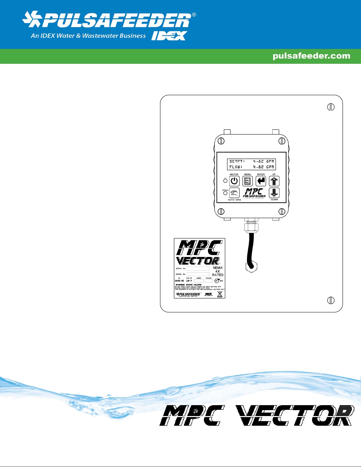
Installation, Operation &
Maintenance Manual
Universal Control
for Pulsa and
Eclipse. Suitable
for any Gear,
Reciprocating or
Positive
Displacement
Pumps.
BULLETIN No. IOM-MPCVector UMPC-11/201010 Rv. A
Microprocessor Based Positive
Displacement Pump Speed Controller
Page 2

MPC VECTOR™ FACTORY SERVICE POLICY
Your MPC VECTOR is a state of the art microprocessor based motor speed controller for use with positive
displacement type pumps. The controller includes extensive on-board diagnostics. If you are experiencing a
problem with your MPC VECTOR, first review the on-screen information, then consult the troubleshooting
guide. If the problem is not covered or cannot be solved, please contact your local authorized Sales
Representative or our Technical Service Department at (585) 292-8000 for further assistance.
Trained individuals are available to diagnose your problem and arrange a solution. Solutions may include
purchasing a replacement unit or returning the unit to the factory for inspection and repair. All returns require
a Return Material Authorization (R.M.A.) number to be issued by Pulsafeeder. Replacements purchased under
a possible warranty situation may be credited after an examination of the original parts by Pulsafeeder
personnel.
Certain components may be purchased for replacement. Refer to 20 Spare Parts for more information and
part numbers. Parts purchased to correct a warranty issue may be credited after examination of the original
parts by Pulsafeeder personnel. Parts returned for warranty consideration that test satisfactorily, will be sent
back to the originator via freight collect.
Any field modifications will void the Pulsafeeder warranty. Out-of-warranty repairs will be subject to
Pulsafeeder’s standard bench fees and testing costs associated with replacement components.
FCC Warning
This device complies with part 15 of the FCC Rules. Operation is subject to the following two conditions: (1)
This device may not cause harmful interference, and (2) this device must accept any interference received,
including interference that may cause undesired operation.
Copyright
Copyright © 2006, 2007, 2008, 2010 Pulsafeeder, Inc. All rights reserved.
Information in this document is subject to change without notice. No part of this publication may be
reproduced, stored in a retrieval system or transmitted in any form or any means electronic or mechanical,
including photocopying and recording for any purpose other than the purchaser’s personal use without the
written permission of Pulsafeeder.
ii
Page 3

Table of Contents
1. MPC VECTOR OPERATION ................................................................................................................... 1
1.1 MPC VECTOR Standard Features ......................................................................................... 1
1.2 Description .............................................................................................................................. 1
1.2.1 System Input/Output Power Ratings ................................................................................ 2
1.2.2 Handheld User Interface Operation .................................................................................. 3
1.2.3 System Modes ..................................................................................................................... 4
1.2.4 Normal System Operational Modes .................................................................................. 5
1.2.5 Control Modes ..................................................................................................................... 6
2. SAFETY CONSIDERATIONS .................................................................................................................... 9
2.1 General Safety ......................................................................................................................... 9
2.2 Electrical Safety ...................................................................................................................... 9
2.3 Mechanical Safety ................................................................................................................... 9
2.4 Hydraulic Safety ...................................................................................................................... 9
3. EQUIPMENT INSPECTION ....................................................................................................................... 10
4. STORAGE INSTRUCTIONS ...................................................................................................................... 10
4.1 Short Term (0 - 12 months) .................................................................................................... 10
4.2 Long Term (12 months or more) ........................................................................................... 10
5. INSTALLATION AND WIRING .................................................................................................................. 11
5.1 Installation Notes .................................................................................................................... 11
5.2 Controller Location ................................................................................................................. 11
5.2.1 Controller Mounting and Layout ....................................................................................... 12
5.2.2 NEMA 4X Version ................................................................................................................ 12
5.2.3 OPEN CHASSIS Panel Mount Version .............................................................................. 14
5.3 Electrical Wiring ...................................................................................................................... 15
5.3.1 Pump Motor Wiring ............................................................................................................. 17
5.3.2 AC Line Input Wiring .......................................................................................................... 17
5.3.3 Control Input/Output Signal Wiring .................................................................................. 23
5.4 Check Wiring and Close Access Cover ................................................................................ 27
6. SYSTEM CONFIGURATION ..................................................................................................................... 27
6.1 Overview .................................................................................................................................. 27
6.2 Critical System Configuration Steps .................................................................................... 27
6.3 Confirm Display and Keypad Functionality ......................................................................... 29
6.4 Motor Parameter Setup .......................................................................................................... 30
6.5 Flow Display and Units .......................................................................................................... 30
6.6 Setting Max Flow and Max Speed ......................................................................................... 30
6.7 Wrapping up ............................................................................................................................ 32
6.8 Factory Re-Initialization ......................................................................................................... 33
7. INPUT/OUTPUT SETUP .......................................................................................................................... 34
7.1 Analog Input Setup ................................................................................................................. 34
7.1.1 Analog Input 1 – Set point ................................................................................................. 34
7.1.2 Analog Input 2 – Flow meter Feedback ............................................................................ 34
7.1.3 Analog Input Testing .......................................................................................................... 34
7.2 Digital Input Setup .................................................................................................................. 35
7.2.1 Multi-purpose Digital Inputs .............................................................................................. 35
7.2.2 Testing Digital Inputs ......................................................................................................... 35
7.3 Analog Output Setup .............................................................................................................. 36
7.4 Digital Output Setup ............................................................................................................... 36
7.4.1 Multi-purpose Digital Outputs ........................................................................................... 36
7.4.2 Testing Digital Outputs ...................................................................................................... 36
8. CALIBRATIONS ..................................................................................................................................... 38
8.1 Pump Flow Calibration ........................................................................................................... 38
8.1.1 Open Loop Pump Flow Calibration ................................................................................... 38
8.1.2 Closed Loop Pump Flow Scaling and Calibration ........................................................... 42
8.1.3 Set point Calibration and Range Setup ............................................................................ 46
iii
Page 4

8.1.4
Analog Output Calibration ................................................................................................. 51
8.2
PulsaGuard Pump Protection ................................................................................................ 52
8.3 Closed Loop Flow PulsaGuard Protection ........................................................................... 53
8.4 Open Loop Speed PulsaGuard Protection ........................................................................... 53
8.4.1 PulsaGuard Calibration - Closed Loop Flow Control ...................................................... 53
8.4.2 PulsaGuard Calibrations- Open Loop Speed Control ..................................................... 54
8.5 Display Contrast Adjustment ................................................................................................. 55
8.6 Tuning the Control Algorithm ................................................................................................ 56
9. FLOW METER INPUT ............................................................................................................................. 59
9.1 Flow Meter Installation and Activation ................................................................................. 59
10. AC INPUT VOLTAGE SETTING ............................................................................................................... 61
11. MOTOR PARAMETER SETUP AND TUNING .............................................................................................. 62
11.1 Motor Parameter Setup and Calibration ............................................................................... 64
12. AL ARM AND ERROR MESSAGES ............................................................................................................ 65
12.1 Error Log .................................................................................................................................. 65
12.1.1 Viewing the Error Log ......................................................................................................... 65
12.1.2 Clearing Error Log Entries ................................................................................................. 65
12.2 Alarm and Error Message System Behavior ........................................................................ 66
13. SPECIFICATIONS ................................................................................................................................... 69
14. PUMP MOTOR SELECTION ..................................................................................................................... 71
14.1 General Specifications ........................................................................................................... 71
14.2 Motor Type and Turndown Requirements ............................................................................ 71
15. MODEL IDENTIFICATION ........................................................................................................................ 73
16. MENU MAPS ......................................................................................................................................... 74
17. FACTORY DEFAULT VALUES ................................................................................................................. 92
18. RETRIEVAL OF SETUP INFORMATION ..................................................................................................... 92
19. TROUBLESHOOTING GUIDE ................................................................................................................... 93
20. SPARE PARTS ...................................................................................................................................... 95
21. APPENDIX 1, HANDHELD WIRING .......................................................................................................... 96
21.1 Removal and Connection of the Cable from the Handheld: ............................................... 96
21.2 Removal and Connection of the Cable from the Base Unit: ............................................... 96
22. APPENDIX 2, PID THEORY AND ADJUSTMENT ........................................................................................ 100
22.1 PID Controller Theory: ............................................................................................................ 100
22.2 Three Control Components: .................................................................................................. 102
22.3 PID Basic Summary, what happens when I… ...................................................................... 103
22.4 Putting it all together to run the MPC Vector ....................................................................... 104
22.5 Troubleshooting ...................................................................................................................... 105
iv
Page 5
Conventions
For the remainder of this bulletin, the following Conventions are in effect.
A WARNING DEFINES A CONDITION THAT COULD CAUSE DAMAGE TO BOTH
THE EQUIPMENT AND THE PERSONNEL OPERATING IT
ATTENTION TO ANY WARNING
Notes are general information meant to make operating the equipment easier.
.
Safety Considerations:
1. Read and understand all related instructions and documentation before attempting to install or
maintain this equipment
. PAY CLOSE
2. Observe all special instructions, notes, and cautions.
3. Act with care and exercise good common sense and judgment during all installation, adjustment, and
maintenance procedures.
4. Ensure that all safety and work procedures and standards that are applicable to your company and
facility are followed during the installation, maintenance, and operation of this equipment.
v
Page 6

Page 7

1. MPC Vector Operation
The MPC VECTOR is a microprocessor based motor speed control device, for use with positive displacement pumps. It
has been designed for simplicity, yet still has many advanced features that allow the MPC VECTOR to operate in a wide
variety of positive displacement pump environments and applications.
Pumps utilizing stroke length control must keep the stroke length constant. For maximum flow rate
adjustment 100% stroke length is recommended.
This product is not just a variable speed drive. It is a state of the art multifunctional controller, which provides
functionally that no one stand-alone variable speed drive does. What makes this product unique is that it combines
functionality of several devices in one:
Vector type variable speed drive.
Input output processor (4-20 mA in and out, digital input/output), including PID loop for closed loop flow control.
A user configurable pump calibration engine allowing process flow units as the main controllable parameter.
A remotely located hand-held local pump control user interface.
Power monitor for detection of run-dry conditions
This instruction manual covers the MPC VECTOR controller only. For information and safety precautions specific
to the pump or any other accessories, please refer to the appropriate IOM.
1.1 MPC VECTOR Standard Features
Local (Manual) and Remote operational modes
User keypad and display for ease of operation (Remote location up to 1000 feet from pump)
Display pump operation in GPH, LPH, GPM, LPM, or RPM
One 4-20 mA analog input signal for flow or speed control
One 4-20 mA analog input for flow feedback control (with an external, user supplied flow meter)
Sensorless vector motor speed control
Two configurable digital dry contact inputs
Three configurable open collector/drain digital outputs (transistor type, 40 VDC maximum)
Analog 4-20 mA output for flow or speed
Available in NEMA 4X (IP56) ratings or an OPEN CHASSIS panel mount
208-230 Volts, 50/60 Hz, single or three phase AC input power for 1-3 HP motors
208-230 Volts, 50/60 Hz, three phase (only) AC input power for 5 HP motors
380,415,440,460,480 Volts, 50/60Hz, 3 phase for 1-5HP motors
Security code lockout of configuration menus
Standard configurable pump protection utilizing proprietary PulsaGuard technology
1.2 Description
The MPC VECTOR is designed for a wide variety of control applications. If delivered with a pump and motor, the
device is factory configured. Field configuration may be required in certain installations. Local setup and control is
achieved through the keypad and a backlit two-line liquid crystal display. Basic operation is simple with dedicated
1
Page 8
function keys eliminating the need for a sophisticated menu system. Pump output is displayed as Gallons or Liters per
Hour (GPH/LPH), Gallons or Liters per Minute (GPM/LPM), or Revolutions per Minute (RPM).
Digital and analog inputs will support a variety of industry standard signals to offer flexible remote control. Digital and
analog outputs provide for system monitoring.
The MPC VECTOR is designed to simplify and automate the calibration of pump flow and analog signals. Flow
calibration uses on-screen prompting and automated pump operation to ease flow setup. Once calibration is provided, all
subsequent flow monitoring may be done using flow units. Analog signal calibration is also accomplished by simple
keypad entry. It includes a real-time display of signal level. This eliminates the need for external meters.
The MPC VECTOR is an advanced pump flow rate controller whose purpose is to precisely adjust output flow of a
process media by means of pump motor speed control. The MPC Vector can be controlled and monitored via remote
SCADA control or a local hand-held user interface. The controller can operate in two system level modes, two
operational modes, and two control modes. See below for detail on mode descriptions.
1.2.1 System Input/Output Power Ratings
The MPC VECTOR will accept, and automatically adjust to, either 50 Hz or 60 Hz input power. No special
modifications, settings, or adjustments are required.
The MPC VECTOR controller can be supplied with a 60 Hz, 50 Hz, or dual rated 50/60 Hz motor. The controller/motor
combination allows for 60 Hz rated pump flow (1800 rpm motor speed) even when operating from a 50 Hz input.
Note: Users in locations with 50 Hz AC supply do not have to de-rate pump flow with this controller.
Minimum motor speed will be pump and motor type dependent and can be user configurable via a turndown ratio to work
with various applications. (See SYSTEM SETUP: turndown/motor setup)
Input Frequency
60 Hz (USA and similar) 60 Hz (or dual rated) 60 Hz / 1800 rpm
50 Hz (Europe, Asia, etc) 50 Hz or 60 Hz or dual rated 60 Hz / 1800 rpm
The motor, used in conjunction with MPC VECTOR controller, whether supplied from Pulsafeeder or by the user must
be a three-phase inverter duty/ready) motor. The three-phase power delivered to the pump motor is generated
internally by the MPC VECTOR controller. Input power ratings provided to the MPC VECTOR can be single-phase
208-230, three-phase 208- 230, or 3 phase 480VAC (see Section 13 Specifications for acceptable voltage ranges and
tolerances). The nameplate on the front of your MPC VECTOR controller will list the appropriate supply requirements
for your controller.
Motor Hp Rating MPC VECTOR Input Voltage* Motor Voltage Rating**
208/230/240 VAC 1 or 3 phase
1
380/415/440/460/480 VAC (3 phase only)
MPC VECTOR Motor Max MPC VECTOR – Output
208-230 VAC
400VAC/460 VAC
2
3
208/230 VAC 1 or 3 phase
380/415/440/460/480 VAC (3 phase only)
208/230 VAC 1 or 3 phase
380/415/440/460/480 VAC (3 phase only)
2
208-230 VAC
400VAC/460 VAC
208-230 VAC
400VAC/460 VAC
Page 9
5
208/230 VAC 3 phase only
380/415/440/460/480 VAC (3 phase only)
Table 1-1 Available MPC Vector Input/Motor Output Ratings
* all input ratings are 50 or 60 Hz
** output to pump motor is always 60 Hz maximum frequency
The AC drive used in the MPC VECTOR maintains tight control over voltage and current supplied to the pump motor,
resulting in lower motor operating temperatures and less stress on motor windings. Control of these key motor parameters
results in longer motor life and more reliable overall operation. Further motor selection information can be found in
Section 14 Pump Motor Selection.
230 VAC
400VAC/460 VAC
1.2.2 Handheld User Interface Operation
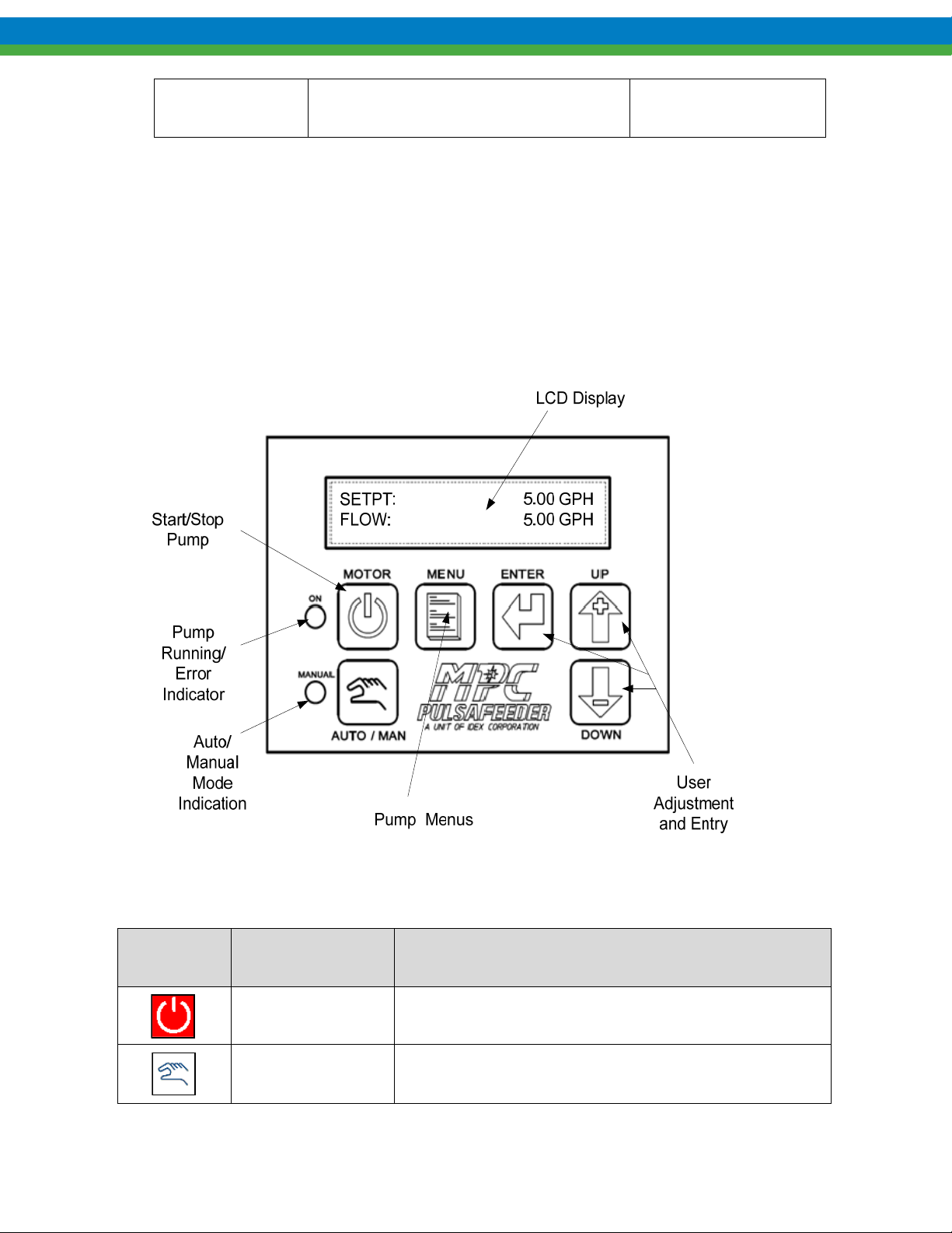
Figure 1-1 Local Handheld User Interface Elements
Key Function Description
Motor On/Off Press to start pump, press again to stop pump
Auto/Manual
Press to toggle between automatic (remote) and manual
(local) control of the pump
3
Page 10
Lamp
ON
MANUAL
Press to adjust controller settings, to exit the menu system,
Menu
Enter
Arrow Up
Arrow Down
Color Description
Off, Green,
Red
Green, Off
to move cursor back when entering values, or to step back to
higher level menus
Press to accept changes in menus, to move cursor forward
when entering values, and to access lower level menus.
Press to increase value, and to scroll up through menu
options
Press to decrease value, and to scroll down through menu
options
Off = Motor off Green = Motor on
Red (blinking) = System Error
Green = Manual (Local) Control
Off = Automatic (Remote) Control
Table 1-2 – Keypad and Lamp Operation
1.2.3 System Modes
The MPC VECTOR operates at two system level modes, normal system control mode and system configuration
mode. Normal system control mode allows the user to change flow rates or motor RPM in order to adjust
process flow conditions to suit their needs. System Configuration mode allows the user to setup the controller
for various user applications, thus customizing the pump rate controller for a particular process.
1.2.3.1 System Configuration Mode
System configuration mode allows the user to set up the pump controller for the particular customer
application. The configuration mode has 4 major categories for the user to setup their pump application. Most
configurations must be done in the pump off state.
Shown below are the major configuration categories and the sub categories within each configuration area.
Configuration
Sub Menu Description
Menu
Calibration
Pump Flow Pump flow calibration for open and closed loop flow setups. 2
Analog Input Allows 4-20 mA signal calibration for speed control in sensorless
Analog Output Provides 4-20 mA output calibration of current output vs. speed in
Motor Provides motor nameplate data entry and calibra tion of the chosen
point calibration
vector speed control and flow in closed loop control.
sensorless vector mode and flow in closed loop mode
4
Page 11
Parameters pump motor.
PulsaGuard Provides setup of run dry feature and calibration
Digital I/O
Digital Input
Digital Output
1&2
1,2 &3
Allows enabling the input, defining whether active high or low,
and defining its use
Allows enabling the output, defining whether active high or low,
and defining its use
Analog I/O
Analog Input 1 Allows activation of the 4-20 mA analog input for open loop
speed or closed loop flow control.
System Setup
Status Provides history of pump status and errors (up to last 4)
Language Allows user to select language
Factory Init Restores pump to factory settings
Flow Units Allows user to set pump flow units GPM, GPH, LPH, LPM
Information Displays system software levels, performing digital/analog
diagnostics, set system turndown, setting pump max flow rate and
speed
Flow Detect Allows setting of flow detection delay time for flow detect digital
input
Flow Meter Allows activation/deactivation of flow m eter for closed loop flow
control
Security Enables/Disables and sets password protection number
PulsaGuard Activate/ Deactivate Run Dry sensing
PID Parameters Allows setting of proportional, integral, and derivative parameters
for closed loop flow meter based systems
TCF
Parameters
Allows the user to change AC drive parameters to suit
motor/pump application.
Table 1-3 MPC Vector System Configuration Menu Items
1.2.4 Normal System Operational Modes
1.2.4.1 Manual (Local) Operational Mode
Manual (also referred to as Local) operational mode requires that the user be present at the pump user interface
(hand-held unit) in order to operate the pump (Note: this location may be up to 1000 ft from the pump). This
mode is indicated by the manual LED being illuminated. A user may, at any time the pump is running, place
the pump into the off condition by pressing the Motor ON/OFF key or place the controller into the
Manual mode of operation, using the Auto/Manual key .
5
Page 12
Operations and monitoring that can occur from local operational mode include the following:
Observation and entry of flow rate and RPM set points
Starting/stopping the pump via Motor On/Off
Motor ON/OFF turns the pump on or off at anytime
Placing the controller between the 2 operational modes, Auto or Manual
Increasing or decreasing flow or motor speed with up/down arrows
Providing system setup, digital I/O setup, Analog I/O Setup, and Calibration via Menu entry
System calibrations – including pump flow, motor, analog I/O, PulsaGuard
Observation of pump status (running/stopped/error) and mode (manual/auto)
1.2.4.2 Auto (Remote) Operational Mode
Auto (also referred to as Remote) operational mode utilizes control signals from a SCADA or PLC
system to control the pump flow (when in closed loop flow mode) or speed (when in sensorless vector
mode) and does not require the user to be present. This allows the MPC VECTOR to be operated
automatically and at remote sites.
Simple remote control can consist of start/stop control (digital dry-contact input). The pump flow rate
for simple control is set in local mode at a fixed user entered flow rate, once set, all remote start/stop
commands via a digital input will command the pump to run at that fixed user flow rate.
More complex flow rate control can be performed by using a 4-20mA current loop and a remote
start/stop digital input signal. The digital input signal will start and stop the pump. The analog input
signal will command the pump motor speed in sensorless vector control and pump flow rate in closed
loop control (flow meter in system configuration).
Operation, control, and monitoring that can be performed while in auto (remote) mode include:
Automatic Start/Stop via Digital Input (set up as Start/Stop).
Process Flow or Speed Set Point Changes with 4-20mA input.
Flow or Speed Monitoring via 4-20 mA output.
1.2.5 Control Modes
The MPC Vector provides two types of flow process control. The flow control methods are dependent
upon whether the user’s system provides an analog flow meter or not.
Sensorless Vector control provides no process flow feedback information and is based upon a flow
rate versus motor RPM calibration. The internal calibration engine calculates the appropriate speed
based upon the user desired flow rate of the pump system.
Closed loop control uses a flow meter placed in the flow path as feedback to the controller board.
The controller, knowing the process fluid flow rate is now able to adjust motor speed based upon a
PID algorithm. See Section 7.1.2 Analog Input 2 – Flow meter Feedback for set up of an analog
flow meter.
6
Page 13
1.2.5.1 Sensorless Vector Flow Control
Sensorless Vector control mode does not use a feedback signal that monitors the flow rate of the process
fluid to the controller. Sensorless Vector control uses a flow rate versus speed algorithm. Flow rates
and speed are entered via a user assisted drawdown calibration procedure in order to derive flow
accuracy (See Section 8.1.1 Open Loop Pump Flow Calibration). The user provides 2 points of
calibration, one point at high speed/flow (maximum motor RPM recommended) and a second point
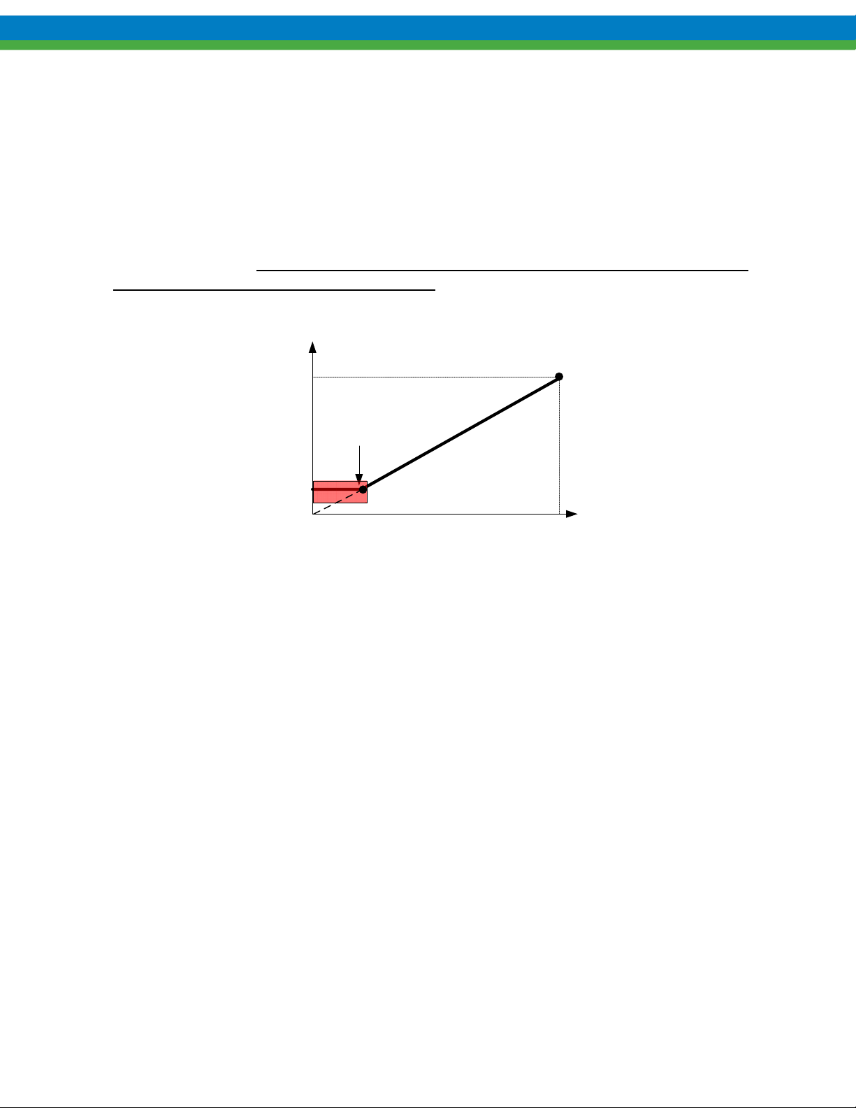
recommended at low motor speed /minimum flow. These 2 points, once characterized, provide a linear
flow relationship for the positive displacement pump application. The flow curve below shows a user’s
two point calibration. Once flows are measured, a speed versus flow conversion is utilized to adjust all
new flow set points. Note: Stroke length must remain constant for sensorless vector control.
Changing stroke length requires recalibration.
SPEED SETPOINT (OPEN LOOP
25
Turndown
Limit
Drawdown
Flow Rate (GPH)
2.4
Reached
FLOW CONTROL – NO
FLOWMETER)
Point 1
(Speed1, Flow1)
Point 2
(Speed2, Flow2)
Figure 1-2 Open Loop Flow Calibration Curve
1.2.5.2 Closed Loop Flow Control
Closed loop flow control utilizes an analog flow meter in conjunction with an internal PID control
algorithm, providing excellent flow control by maintaining process flow set point. Flow meter
feedback must be in the form of a 4-20 mA signal representing process flow rates. The flow meter
should be located as close as possible to the pump in order to provide a measurement of the current
process flow rate without flow rate time lag introduced into the feedback loop (delayed flow readings
will cause flow stability issues). The analog flow signal (see flow meter setup Section 7.1.2 Analog
Input 2 – Flow meter Feedback for details) is fed into MPC Vector Analog Input 2, and is activated in
the System Setup menu under the sub-category of Flow Meter.
175 1750
Speed Setpoint
(Handheld Remote)
7
Page 14
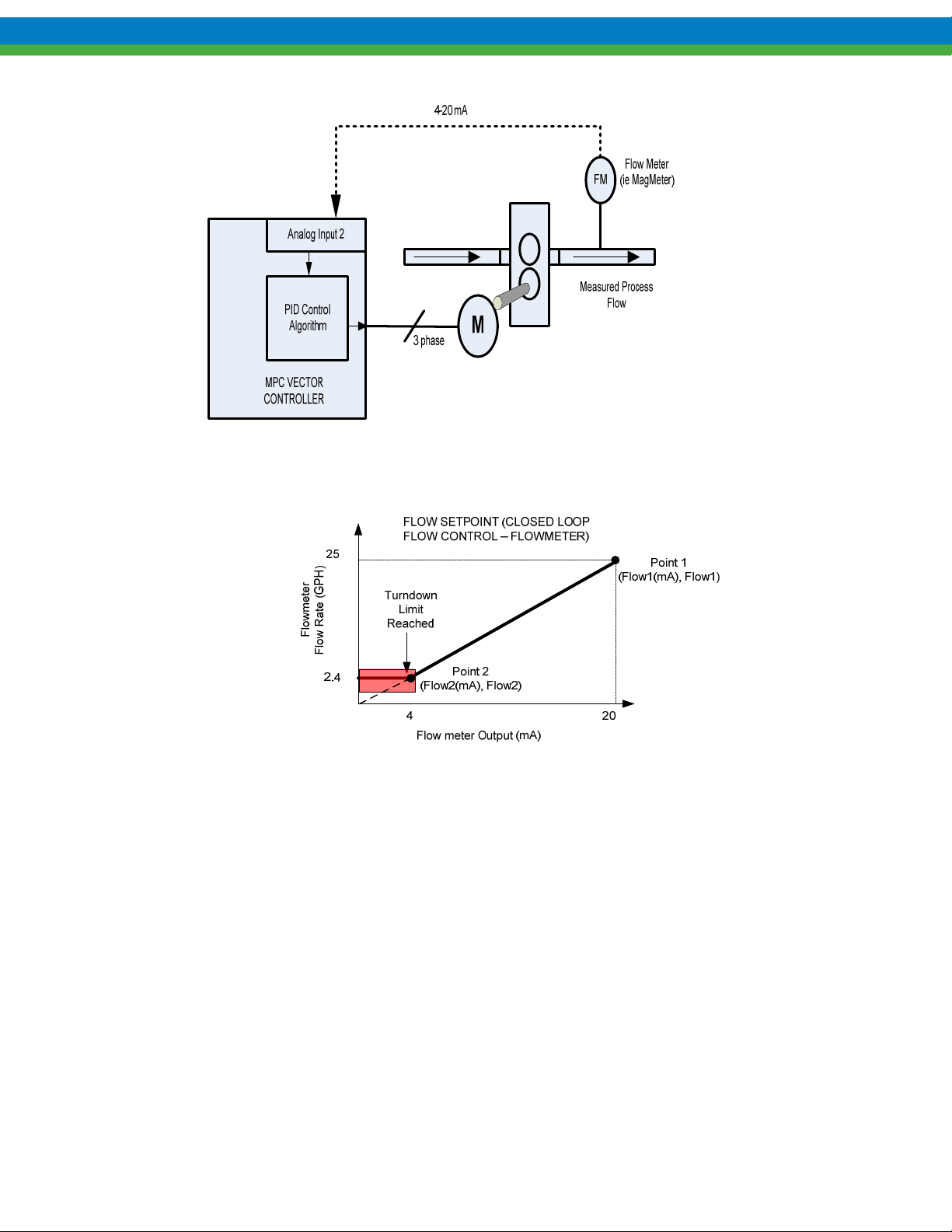
Figure 1-3 Closed Loop Control Feedback Block Diagram
Figure 1-4 Closed Loop Flow Calibration Curve
8
Page 15

2. Safety Considerations
Read and understand all related instructions and documentation before attempting to install or maintain this
equipment.
Observe all special instructions, notes, and cautions.
Act with care and exercise good common sense and judgment during all installation, adjustment, and maintenance
procedures.
Ensure that all safety rules, work procedures, and standards that are applicable to your company and facility are
followed during the installation, maintenance, and operation of this equipment.
2.1 General Safety
The MPC VECTOR was designed as a pump rate controller for operation with positive displacement type pumps.
Use for any other application is considered unsafe and voids all certification markings and warranties.
2.2 Electrical Safety
The MPC VECTOR is an industrial process controller. Improper application and use can be hazardous. You are
solely responsible for its use.
The MPC VECTOR electrical installation must conform to all relevant electrical codes. Installation and electrical
maintenance must be performed by a qualified electrician. Before installing or servicing this device, all power must
be disconnected from the source at the main distribution panel.
The MPC VECTOR emits electro-magnetic energy and may generate radio frequency interference. Its use is
restricted to industrial applications. You are responsible for shielding this energy/interference.
Certain wiring procedures may require that the user wear a wrist strap to dissipate static charges.
Wait a minimum of 5 minutes after disconnecting power before servicing the MPC VECTOR or pump
motor. Capacitors retain a charge even after power is removed from the controller.
2.3 Mechanical Safety
Users should note that the pump motor is always under the control of the MPC VECTOR, and as such may actuate
without warning. Care should be taken to keep loose clothing and other objects away from the pump motor.
The MPC VECTOR was designed to be service free. It contains no user-maintainable components. Disassemble
the MPC VECTOR enclosure only for initial field wiring, or as instructed to do so within this manual. Evidence of
unauthorized disassembly shall void the warranty.
2.4 Hydraulic Safety
Thoroughly review and adhere to the contents of your particular pump Installation, Operation, Maintenance and
Instruction manual for any pump used with the MPC Vector control. As a microprocessor controlled device, the
MPC VECTOR may activate the pump motor without warning – generating hydraulic pressure and fluid flow.
Care should be taken to protect both users and systems should the pump activate.
9
Page 16

3. Equipment Inspection
When you receive your order, check all equipment for:
Completeness against the shipping document / purchase order
For any evidence of shipping damage
Shortages or damage should be reported immediately to the carrier and your Pulsafeeder Representative.
4. Storage Instructions
The MPC VECTOR can be successfully stored for extended periods. The key to successful storage is dependent on
temperature and humidity control.
4.1 Short Term (0 - 12 months)
The MPC VECTOR should be stored in a temperature and humidity controlled environment. It is preferable to
keep the temperature constant in the range of -18 to 60 Celsius (0 to 140 Fahrenheit). The relative humidity
should be 0 to 90% non-condensing.
4.2 Long Term (12 months or more)
Storage of the MPC VECTOR for periods of longer than twelve months is not recommended. If extended storage
is unavoidable the MPC VECTOR should be stored in accordance with those conditions stipulated for Short Term
Storage. In addition, a porous bag of 85g (3 oz) silica gel or similar desiccant should be placed inside the
enclosure. The cover should be re-installed to seal the desiccant within the enclosure. The conduit connections
must be tightly capped.
Special note for long-term storage:
If AC input power has not been applied to the MPC VECTOR for a period greater than 12 months, the controller
must be prepared for operation. The MPC VECTOR should have AC power applied at the input for a period of 8
hours before placing pump into normal operation. Refer to Installation and Wiring section for AC power
connection instructions.
10
Page 17
5. Installation and Wiring
5.1 Installation Notes
The MPC VECTOR is a microprocessor-based controller that uses electro-static sensitive CMOS components. Do
not make any (high or low voltage) electrical connections without adequately grounding the MPC VECTOR and
the worker to eliminate an electro-static charge between the two.
A CONDUCTIVE WRIST STRAP WORN BY THE WORKER AND ATTACHED TO THE MPC
VECTOR’S INTERNAL GROUND PLATE IS ADEQUATE TO SATISFY THIS REQUIREMENT.
Calibration is an important element of successful MPC VECTOR operation. If a flow meter is being used for
process feedback the flow meter must be calibrated by the supplying manufacturer prior to MPC VECTOR
calibration according to manufacturer recommendations.
Conduit connections can carry fluids and vapors into the MPC VECTOR causing damage and void the warranty.
Care should be taken when installing conduit to protect against fluid/vapor entry. If necessary, provide sealed
entries or conduit drains near the point of entry. The user must supply the correct connection for the power entry,
as per the local codes and requirements. Any cable entrances that are not used should be appropriately sealed
against moisture and vapors.
5.2 Controller Location
The following section describes the installation steps necessary for a successful installation.
Review the Safety section (Section 2) prior to installing the MPC VECTOR. It contains information required to
properly install and operate the MPC VECTOR in an industrial environment.
The site selected for the installation of your MPC VECTOR is largely dependent on your particular pump(s)
physical location. Review the Installation, Operation, and Maintenance manual provided with your particular pump
type. The Installation, Operation, and Maintenance manual details system related issues that are important to
proper operation of the pump.
Consider the following MPC VECTOR installation related issues when selecting an installation site.
Location of the controller enclosure must be within 100 feet (30.5 meters) of the pump motor, otherwise
consult factory on longer distances if necessary.
Avoid locations where the MPC VECTOR would be subjected to extreme cold or heat (<0 or >40 Degrees
Celsius, <32 or >104 Degrees Fahrenheit). Note the warning statement on the next page. The installation
of this device must comply with national, state and local electrical codes.
Location for the handheld device used to display flow and control manual operation of the pump, a
maximum of 1000 feet (305 meters) is allowed.
The MPC VECTOR controller must be secured to an appropriate support before use. Use appropriate hardware to
secure the MPC VECTOR controller to a smooth vertical surface.
11
Page 18
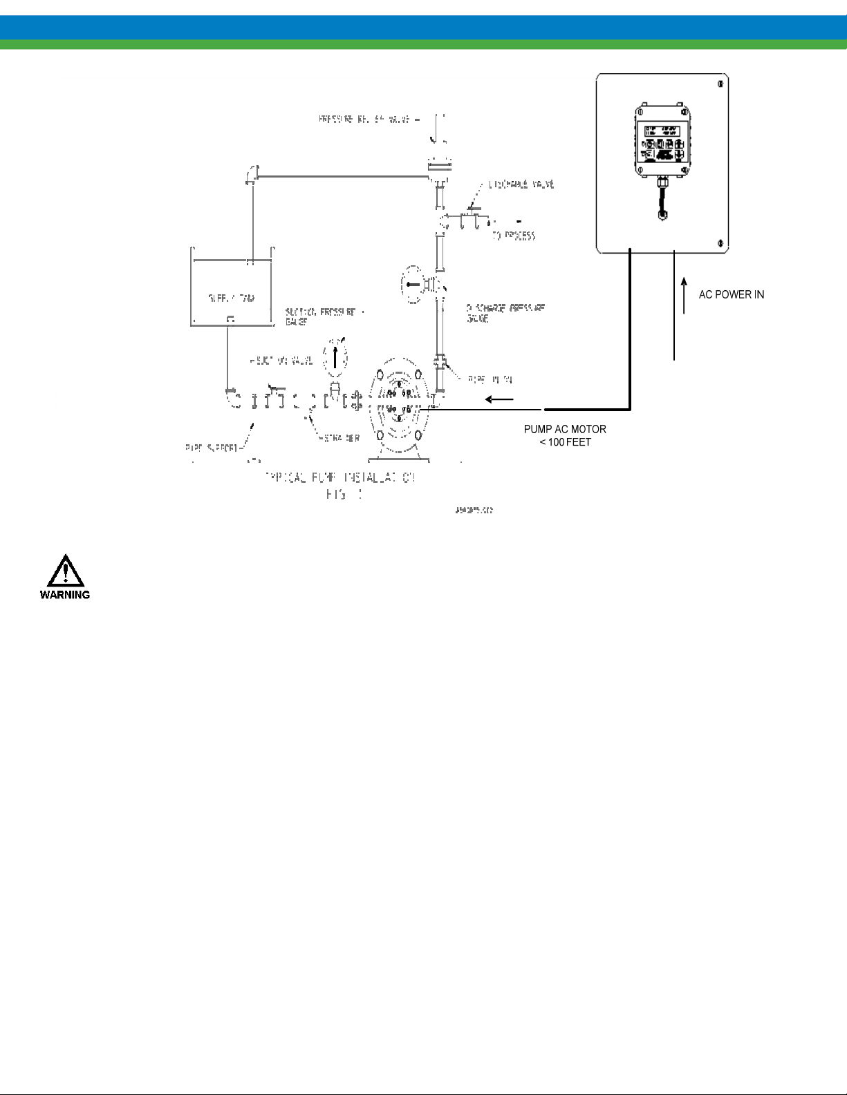
Figure 5-1 – Typical Installation (Gear Pump Shown)
AVOID LOCATIONS WHERE THE MPC VECTOR WOULD BE SUBJECTED TO EXTREME COLD OR HEAT
[LESS THAN 0 CELSIUS (32 FAHRENHEIT) OR GREATER THAN 40 CELSIUS (104 FAHRENHEIT)] OR
DIRECT SUNLIGHT
ITS WARRANTY
. FAILURE TO OBSERVE THIS WARNING COULD DAMAGE THE MPC VECTOR AND VOID
.
The MPC VECTOR is provided in two form factors, a NEMA 4X enclosure, and an OPEN CHASSIS custom
mountable panel.
5.2.1 Controller Mounting and Layout
The MPC VECTOR is provided in two form factors, a NEMA 4X enclosure, and an OPEN CHASSIS custom
mountable panel.
5.2.2 NEMA 4X Version
The NEMA 4X design, both 230VAC and 480 VAC, of the MPC VECTOR incorporates all control circuitry onto
one easily accessed control panel. This controller circuitry is located on the inside of the main controller enclosure.
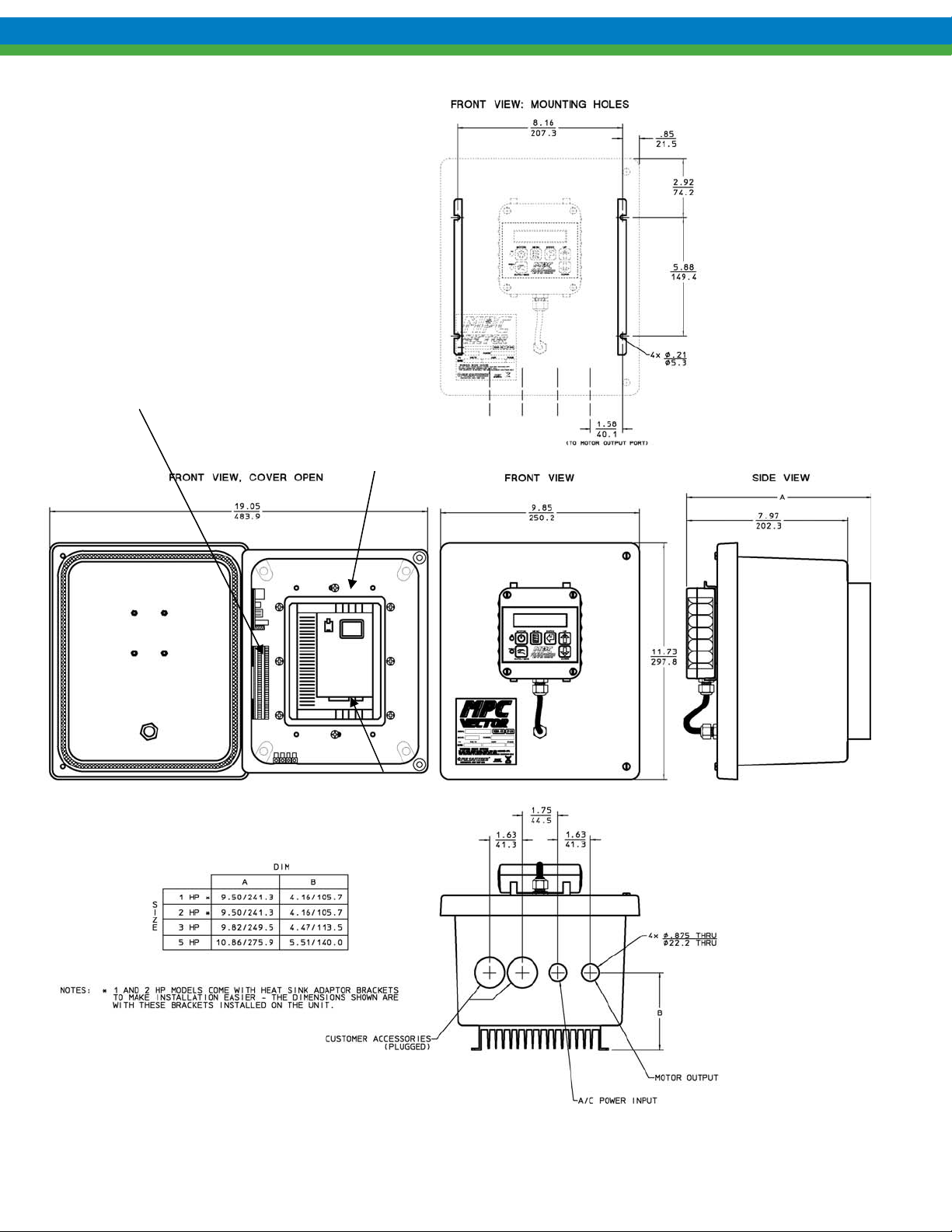
Gain access to this circuitry by removing the 2 cover screws to the hinged enclosure. See Figure 5-2 – NEMA 4x
12
Page 19
W
g
230/480 VAC Controller Layout and Dimensions for detailed mounting dimensions
Control
I/O
Wiring
AC Input
wiring
Pump Motor
irin
Figure 5-2 – NEMA 4x 230/480 VAC Controller Layout and Dimensions
13
Page 20

5.2.3 OPEN CHASSIS Panel Mount Version
The OPEN CHASSIS design of the MPC VECTOR incorporates all control circuitry onto one easily accessed
open-frame chassis for 230 VAC designs. Note: 480 (3 phase) VAC designs require a control transformer to step
down one phase of 480VAC to 230 VAC for control electronic power supply. The main MPC Vector control
board is located on the left hand side of the panel. See Figure 5-3 OPEN CHASSIS Panel Mount Controller
Layout and Dimensions for detailed mounting dimensions.
14
Page 21
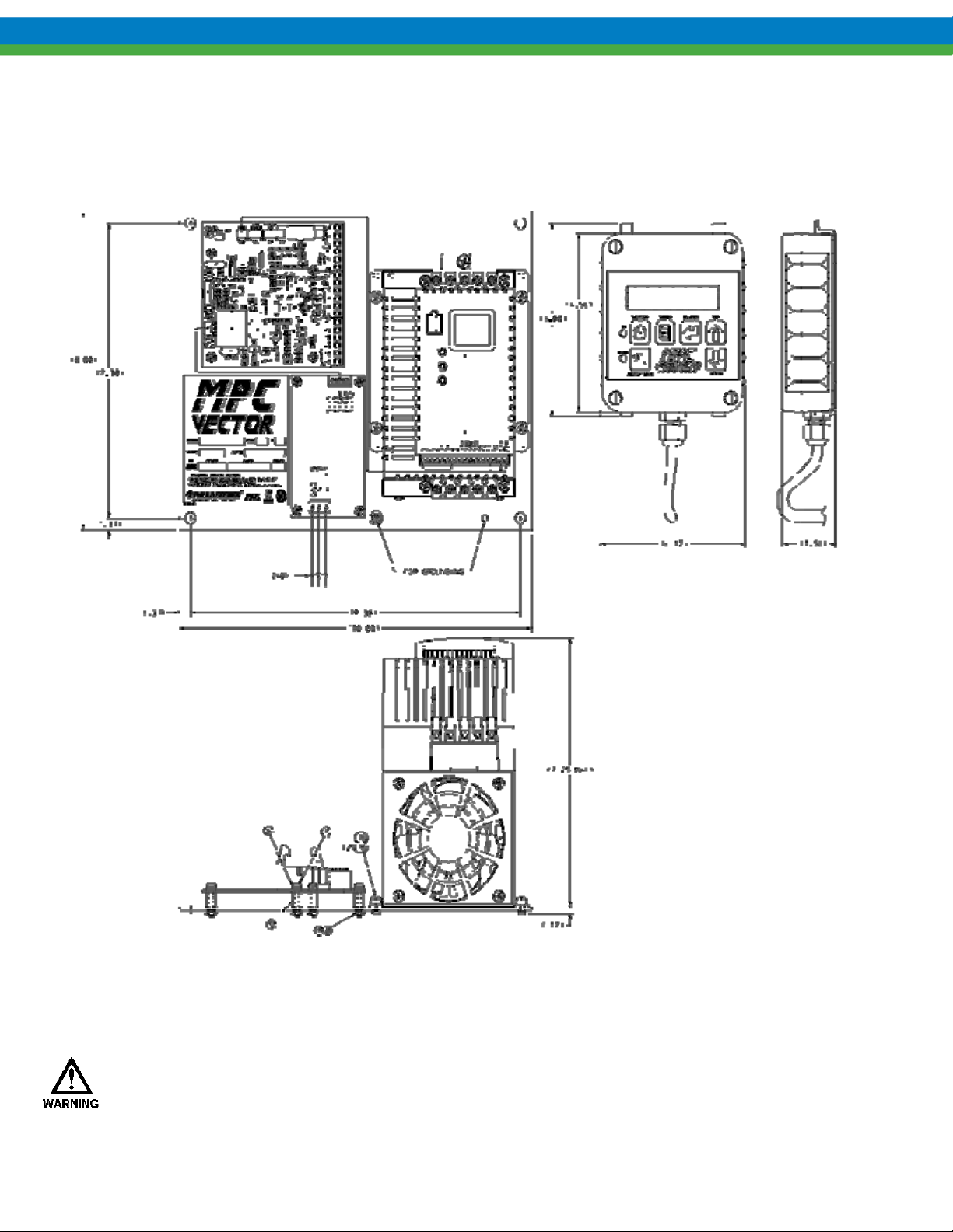
Figure 5-3 OPEN CHASSIS Panel Mount Controller Layout and Dimensions
5.3 Electrical Wiring
IF THE CONTROLLER WAS PREVIOUSLY POWERED, WAIT A MINIMUM OF 5 MINUTES AFTER
DISCONNECTING POWER BEFORE SERVICING THE MPC VECTOR OR PUMP MOTOR.
CAPACITORS RETAIN A CHARGE EVEN AFTER POWER IS REMOVED FROM THE
CONTROLLER.
15
Page 22

Shown below is a summary of the electrical wiring steps necessary to install an MPC VECTOR (see
appropriate sections to follow for details)
1. Connect the 3 phase pump motor.
2. Connect the Supply Voltage, single or three phase.
3. (Optional) Connect your pump’s application control wiring
a. Analog input signal(s), so the MPC VECTOR can accept a process input signal or flow meter input
b. Analog output signal, for user monitoring of speed or flow
c. Digital input signals, for example start/stop and/or tank level inputs
d. Digital output signals, for example auto/manual status and/or alarm outputs
4. Conduct a final power-up and test the MPC VECTOR
5. Go to Section 6 System Configuration for details on how to configure I/O and perform power-up tests
16
Page 23
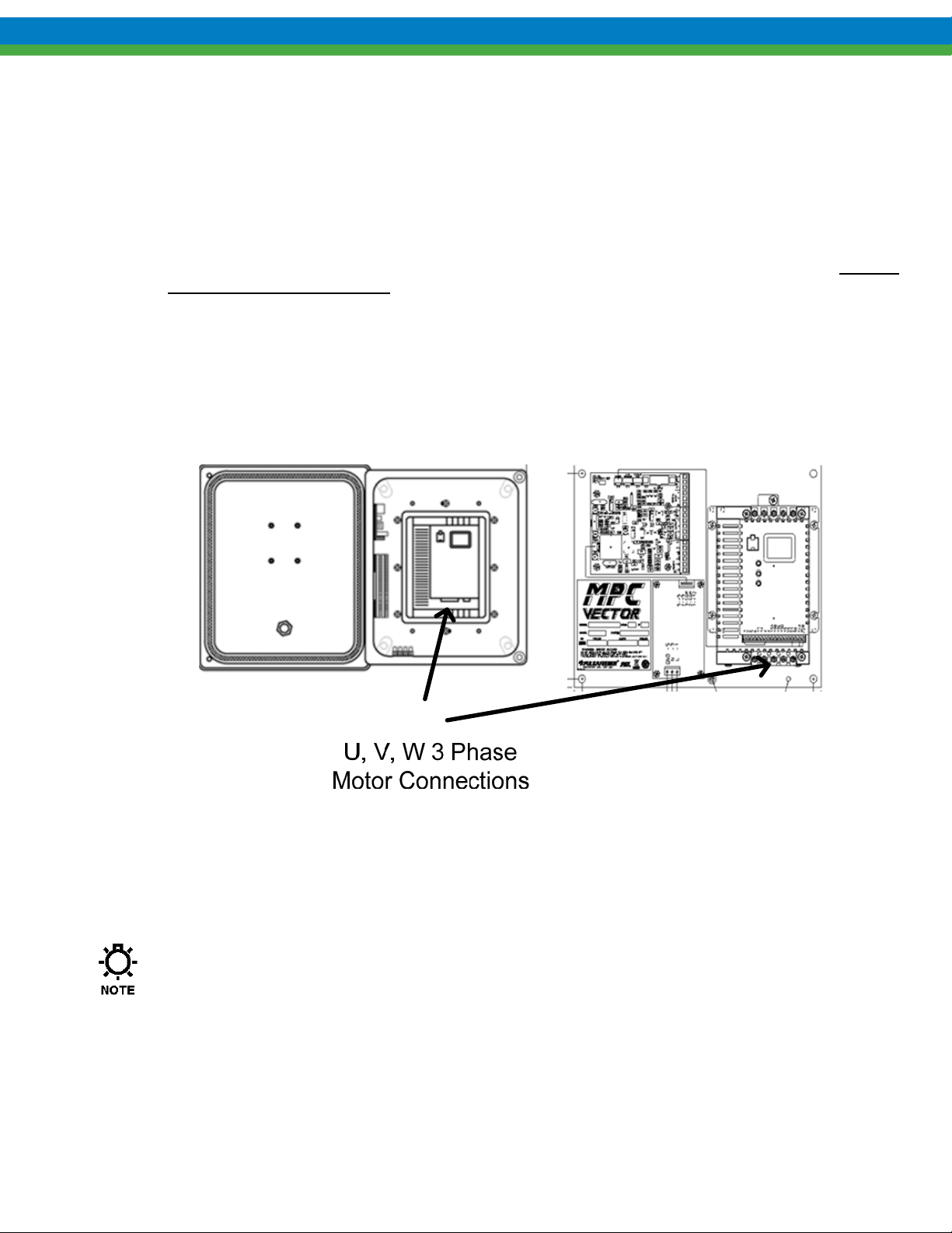
5.3.1 Pump Motor Wiring
Using a VFD rated cable route the 3 phase motor connections between the MPC Vector AC drive
connections marked U, V, and W as shown in Figure 5-4 MPC VECTOR Pump Motor Wiring
Termination below. Next terminate the VFD cable at the pump motor location, being careful to wire the
proper motor voltage connections (generally L1, L2, L3, refer to your motor voltage wiring diagram for
dual voltage rated motors).
The motor wires are secured to the terminal strip at the bottom end of the AC drive. Remove
approximately 0.20 – 0.25” of insulation from the end of each conductor. Loosen the terminal strip screw,
and insert the stripped wire end fully into the terminal. Tighten the screw to secure the conductor (Torque
Requirement 2.0 lb-in/0.2 Nm) making certain that the terminal grips the wire, not the insulation.
Ensure that all wiring meets applicable local and national codes and requirements.
Ensure that the motor voltage wiring connections (230/480 VAC) match your MPC Vector voltage rating
by referring to the motor wiring diagram on motor conduit cover. Use the nameplate voltage rating of the
MPC Vector.
Figure 5-4 MPC VECTOR Pump Motor Wiring Termination
5.3.2 AC Line Input Wiring
Verify the correct supply voltage (230VAC single/three phase or 480VAC three phase) with the
nameplate affixed to your MPC VECTOR. Ensure that your AC line input voltage matches the
MPC VECTOR configuration.
The 1 hp, 2 hp, and 3 hp rated MPC VECTOR use single phase or three phase 208-230VAC input.
The 5 hp 230 VAC MPC VECTOR must be powered by three phase input only.
All 480VAC MPC VECTOR use 3 phase power only.
17
Page 24

Wires should be routed within the enclosure in a manner that maintains separation between high
voltage (power) and low voltage (control) conductors. High voltage conductors should be routed to
the side opposite the control circuitry.
Incoming power wiring should adhere to all applicable local and national electrical codes and
regulations. A circuit breaker or fuse(s) must be provided as noted below.
Upon initial application of AC power, a current inrush will occur to charge the DC bus capacitors.
This is normal operation, and breakers and other circuit protection devices should be sized
accordingly.
Motor Rated circuit breakers are recommended for use (allows input surge).
Wiring Torque Requirement 2.0 lb-in/0.2 Nm.
Wire and Ground in accordance with NEC or CEC, and all applicable codes.
Motor wire must run in separate conduit away from control wires and AC line input.
Do not install contactors bewteen the MPC Vector and the motor.
Use only UL and CSA approved wire.
Use 300V rated wire for 208/240 VAC systems and 600V for 400/480VAC systems.
Wire gauge must be based on a minumum of 125% of the rated input/output current of the drive,
and a minimum 75 Degrees C insulation rating. Copper wire only.
5.3.2.1 AC Input Wire and Circuit Breaker Sizing
General Input Wiring Guidance
The MPC VECTOR requires one connection to an external AC power source. The controller uses this AC
connection to power its own internal supply and the AC pump motor. You must take all of these loads into
consideration when sizing the branch circuit. A circuit breaker or disconnect switch with fuses must be wired in
series with terminals L1 and L2/N (single phase) and L1, L2, and L3 (three phase) in accordance with all
applicable local and national electrical codes and regulations. The circuit breaker or disconnect switch shall be
located in close proximity to the MPC VECTOR controller installation, and must be marked or labeled to identify
it as the power disconnect for the MPC VECTOR.
Conduit Entrance
The MPC VECTOR controller is provided with a 7/8” thru hole for incoming AC power wiring and a 7/8” thru
hole for motor wiring at the bottom of the enclosure. Utilize the appropriate conduit fittings to route and seal the
supply wires into the MPC VECTOR enclosure.
Depending on the model you are installing see the appropriate sections below for 230 or 480 VAC to
determine proper AC installation guidelines. See nameplate for HP rating, refer to Figure 5-5 MPC
VECTOR Product Label.
18
Page 25
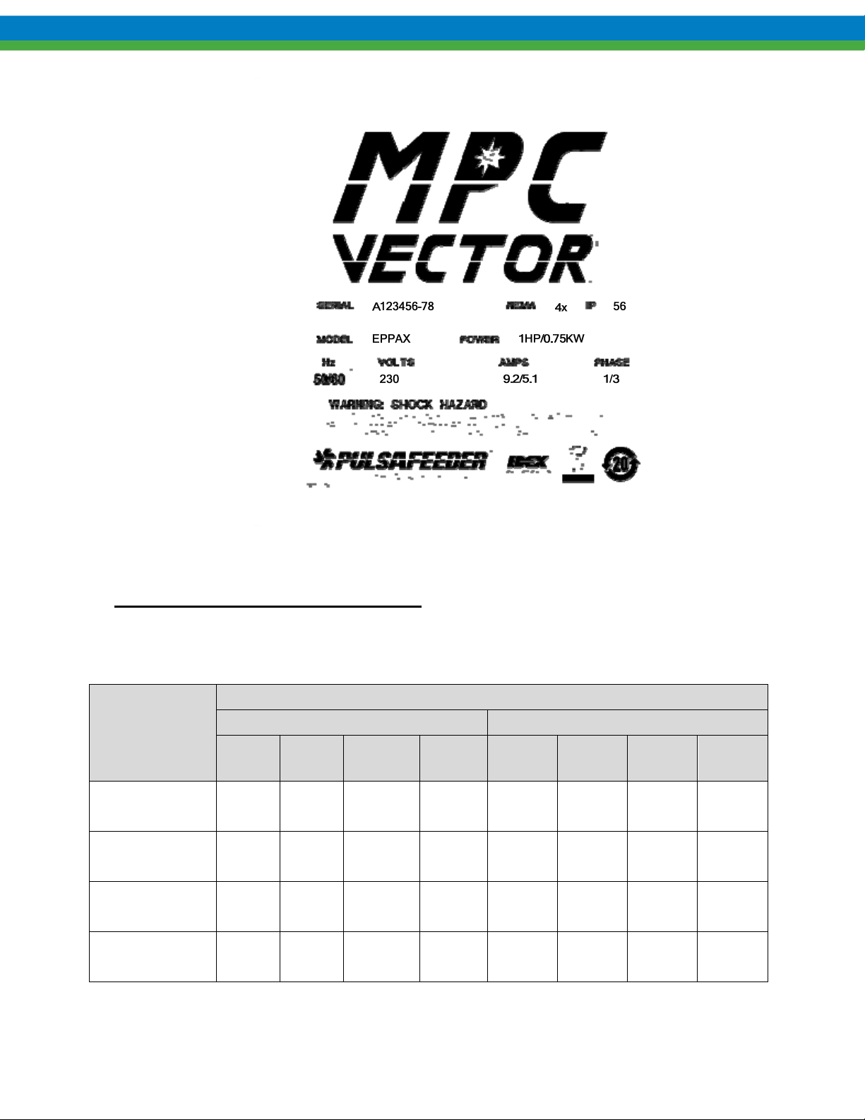
Figure 5-5 MPC VECTOR Product Label
230 VAC Models - Single and Three Phase
See Table 5-1 Sizing Branch Circuits (208/230VAC) below for recommended wire and circuit breaker
sizing information.
Recommended Minimum Wiring and Circuit Breaker
Power
Requirements
MPC VECTOR
and 1.0 Hp motor
MPC VECTOR
and 2.0 Hp motor
MPC VECTOR
and 3.0 Hp motor
Actual
10.6 A 15 A 14 AWG 2.0 mm
14.8 A 20 A 12 AWG 3.5 mm
19.7 A 25 A 12 AWG 3.5 mm
Single Phase 208/230 VAC Three Phase 208/230 VAC
Draw
Circuit
Breaker
Wire
Size
Wire
Size
Actual
Draw
2
5.8 A 10 A 14 AWG 2.0 mm
2
9.1 A 15 A 14 AWG 2.0 mm
2
12.4 A 20 A 12 AWG 3.5 mm
Circuit
Breaker
Wire
Size
Wire
Size
2
2
2
MPC VECTOR
and 5.0 Hp motor
--- --- --- --- 19.6 A 25 A 12 AWG 3.5 mm
2
Table 5-1 Sizing Branch Circuits (208/230VAC)
19
Page 26
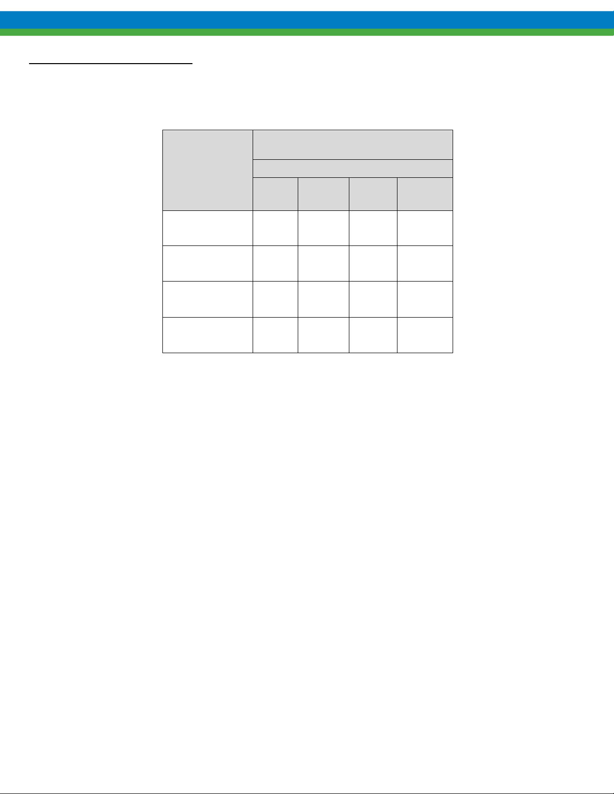
480 VAC Models – Three Phase
See Table 5-2 – Sizing Branch Circuits (400/480VAC) below for recommended wire and circuit breaker
sizing information.
Requirements
Power
Recommended Minimum Wiring and Circuit
Breaker
Three Phase 400/480 VAC
Actual
Draw
Circuit
Breaker
Wire
Size
Wire
Size
MPC VECTOR
and 1.0 Hp motor
MPC VECTOR
and 2.0 Hp motor
MPC VECTOR
and 3.0 Hp motor
MPC VECTOR
and 5.0 Hp motor
2.9 A 7 A 14 AWG 2.0 mm
4.5 A 7 A 14 AWG 2.0 mm
6.2A 10 A 14 AWG 2.0 mm
10.6 15A 14 AWG 2.0 mm
2
2
2
2
Table 5-2 – Sizing Branch Circuits (400/480VAC)
5.3.2.2 230 VAC Model NEMA 4x and 480VAC Panel Mount Line Wiring
Make the incoming 230VAC power connections, paying particular attention to whether the installation is single or
three phase. See Figure 5-6 230 VAC Single and Three Phase Line Input Wiring and Table 5-3 230VAC
Single and Three Phase Terminal Connection Guide to assist with wiring details. Note that wiring for 230 VAC
models is routed directly to the top of drive terminals.
20
Page 27
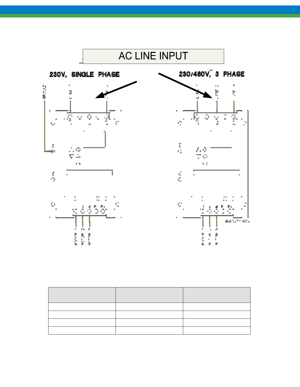
Figure 5-6 230 VAC Single and Three Phase Line Input Wiring
**Note: 480 VAC Panel Version wired directly into drive
MPC VECTOR Drive
Terminal
L1 Line 1 Line 1
L2 N/C(No Connect) Line 2
L3 Line 2/Neutral Line 3
Ground Plate Chassis/Earth Ground Chassis/Earth Ground
Table 5-3 230VAC Single and Three Phase Terminal Connection Guide
**480 VAC Panel Mount has AC connected directly to the drive
Single Phase 208/230 VAC
21
Three Phase
208/230/480** VAC
Page 28
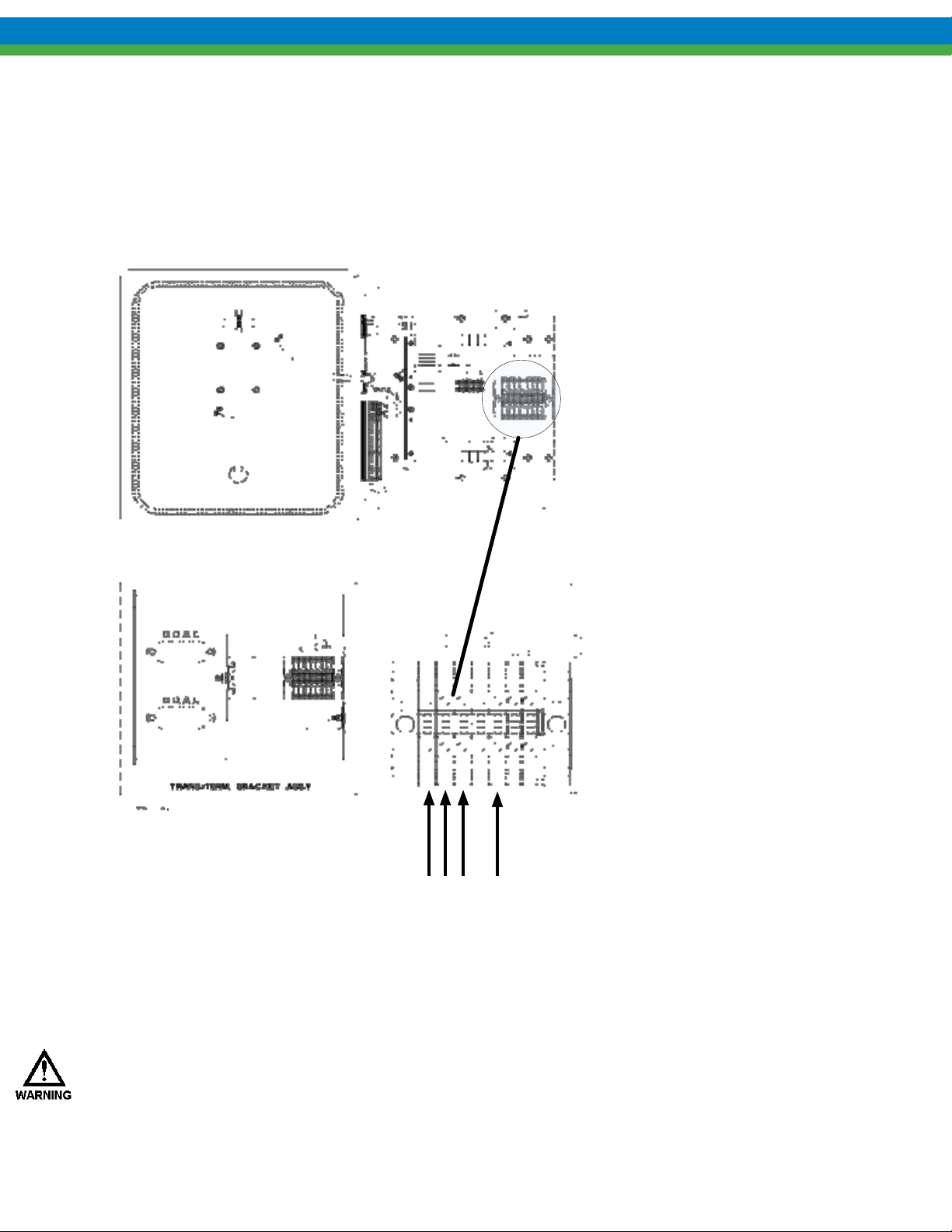
5.3.2.3 480 VAC NEMA 4x Enclosure Input Wiring
Make the incoming 480 VAC three phase power connections. See Figure 5-7 480VAC NEMA 4x AC Input
Wiring Termination Details to assist with wiring details. Note that input wiring for 480 VAC NEMA 4x models
is routed to a supplied terminal strip block.
Figure 5-7 480VAC NEMA 4x AC Input Wiring Termination Details
At this point power wiring is complete. At this point you should apply power to the MPC VECTOR and
your attached pump to ensure proper power wiring connection. See Section 6 for start-up screen
information. Do not attempt to start the pump until MPC Vector configuration has been completed in
Section 6 .
WAIT A MINIMUM OF 5 MINUTES AFTER DISCONNECTING POWER BEFORE SERVICING THE MPC
VECTOR OR PUMP MOTOR. CAPACITORS RETAIN A CHARGE EVEN AFTER POWER IS REMOVED
FROM THE CONTROLLER.
22
Page 29
5.3.3 Control Input/Output Signal Wiring
5.3.3.1 Determination of Input and Outputs
Based upon system configuration and control required, decide which control signal Inputs and Outputs (i.e.,
remote start/stop, 4-20mA in/out, etc.) will be used for your pump application and make the appropriate digital
and analog connections. See details of control connections below.
5.3.3.2 Routing
Signal wiring is routed through the two leftmost unused conduit openings Figure 5-2 – NEMA 4x 230/480
VAC Controller Layout and Dimensions at the base of the MPC VECTOR (NEM4x enclosures, panel version
based upon on conduit entry). All input/output signals are connected to the terminal strip at the edge of the
MPC VECTOR circuit board. Use caution to observe proper wire location and signal polarity. Wires should
be routed within the enclosure in a manner that maintains separation between high voltage and low voltage
conductors. Ensure all low voltage wiring is installed per any applicable local and national electrical codes and
regulations
Unused conduit openings should be plugged as required to avoid ingress of moisture and contaminants into the
MPC VECTOR enclosure. Do not remove the factory provided plug from openings that are not required for
field wiring.
.
5.3.3.3 Suggested Cable
Utilize 16 to 22 AWG stranded, 250 V shielded cable with a 75o C insulation rating (or better) for all signal
input and output wiring. Recommended strip length is 0.39” or 10 mm.
5.3.3.4 Control Terminal Strip Termination Description
IT IS RECOMMENDED THAT A GROUNDING (ESD) WRIST STRAP BE WORN WHEN MAKING CONNECTIONS TO
ANY PRINTED CIRCUIT BOARD
.
The MPC VECTOR terminal strip mapping is shown in Figure 5-8 –I/O Terminal Strip Details
(Panel & NEMA4x Shown). The terminal strip is composed of 5 major connection areas:
Remote Handheld Interface
Digital Output Interface
Analog Output Interface
Digital Input Interface
Analog Input Interface
See the appropriate control wiring sections for example I/O wiring and terminal strip locations. Customize the I/O
wiring for your pump configuration.
23
Page 30
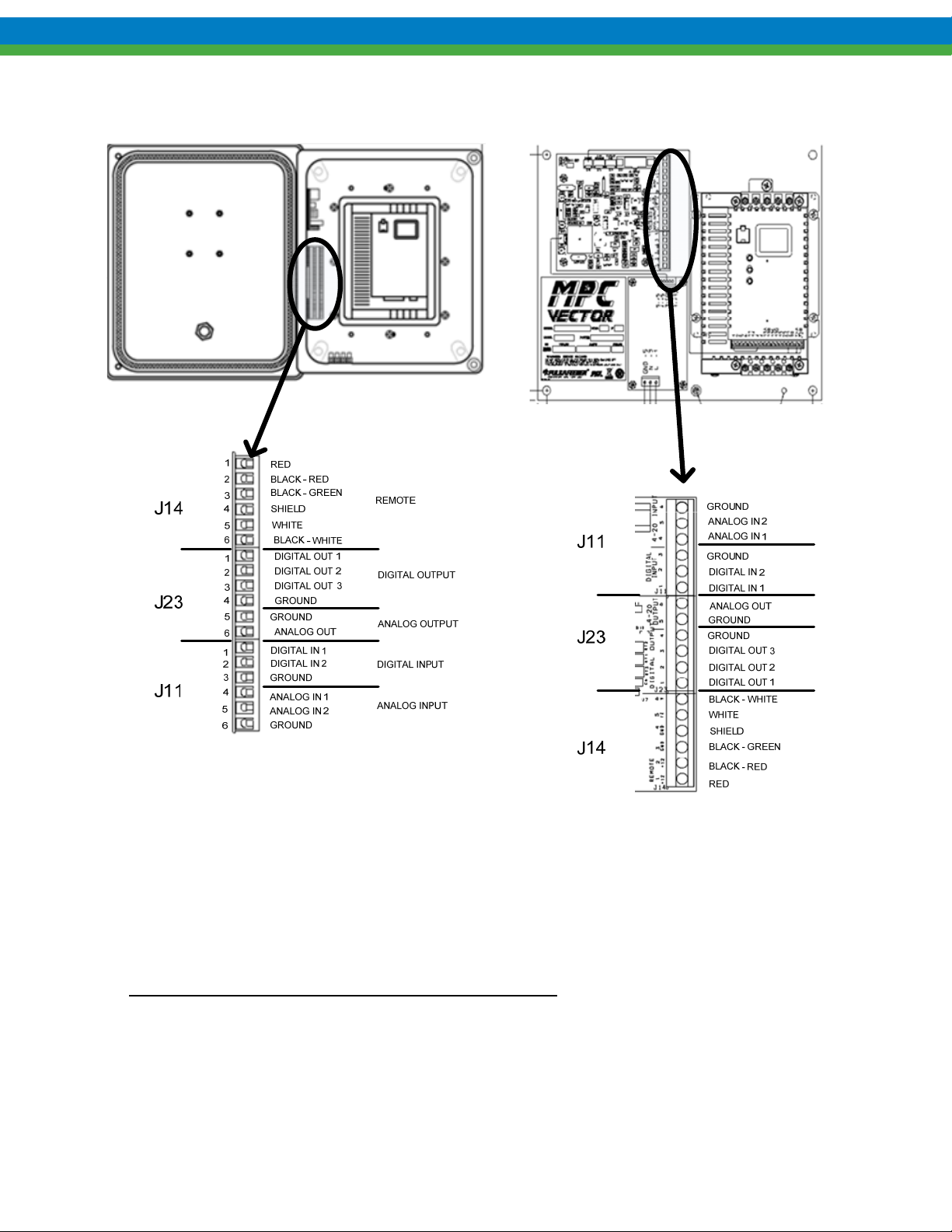
Figure 5-8 –I/O Terminal Strip Details (Panel & NEMA4x Shown)
5.3.3.5 Digital Output Wiring Example (Open Collector/Drain)
MPC VECTOR Digital non-isolated output signals can drive DC (direct current) devices such as
LED’s, relays, indicator lamps, or any device that does not require more than 500mA of current.
Activation of a digital output from the MPC VECTOR provides a low impedance connection to the external
power supply’s ground, allowing current flow through the user device.
(Warning: MPC VECTOR Outputs are not relay contacts)
An external 24 VDC power supply must be supplied. Digital Outputs 1-3 consist of an open collector/drain
current sinking low side switch capable of sinking 500 mA. The maximum external voltage that may be applied
to these digital outputs is 40 VDC (see Section 13 Specifications, for more information).
24
Page 31
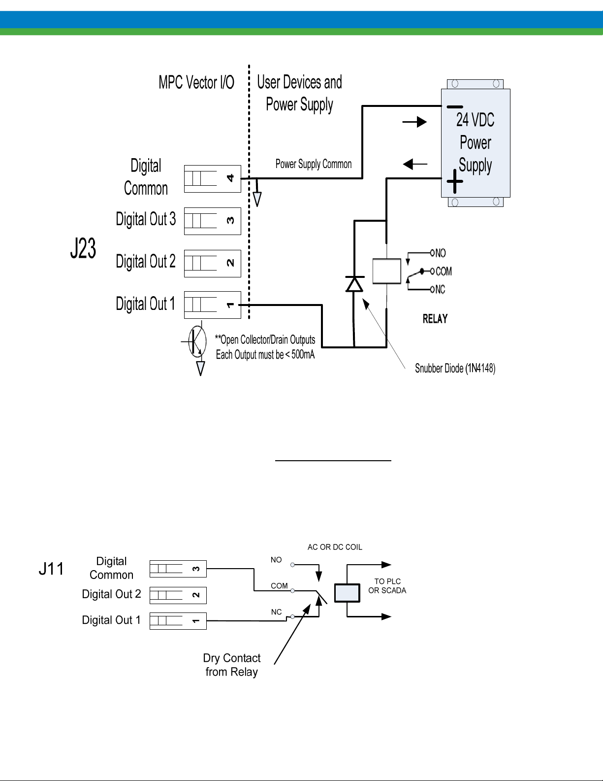
Figure 5-9 – Sample Digital Output Connections, (power can be in the range of 5 – 40 VDC)
5.3.3.6 Digital Input Example Wiring
Digital Inputs 1 and 2 provide monitoring of dry contact (voltage free) type inputs. Contact resistance when
closed must not exceed 500 ohms in order to be recognized as an active closure. Inputs can be wired normal open
or normally closed. See example below.
Warning: do not apply any voltage type outputs to these inputs, damage will occur.
Figure 5-10– Sample Digital Input Connections
25
Page 32
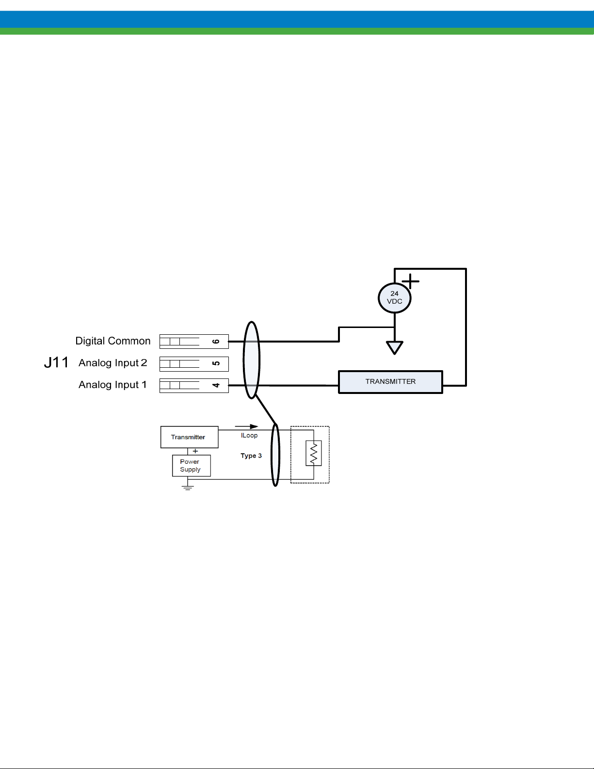
5.3.3.7 Analog Input Wiring Example
Analog inputs require a loop powered (current sourcing) transmitter capable of driving a minimum 250
ohm resistive load. The transmitter maybe a two wire or three wire type. The analog inputs are not
isolated. Some installations may require an analog input isolator. See Figure 5-11– Sample Analog
Input Connections below for wiring details.
5.3.3.7.1 Flow Meter (Analog Input 2)
Analog input 2 is dedicated for flow meter based systems. The analog input is use to provide a 4-20
mA flow feedback signal in order to provide closed loop flow control.
5.3.3.7.2 Set point (Analog Input 1)
Analog input 1 is dedicated as a user set point input. The analog input is used to command speed
(which is proportional to flow) in open loop systems and flow rated for closed loop systems.
Figure 5-11– Sample Analog Input Connections
5.3.3.8 Analog Output Example Wiring
The MPC Vector provides internally powered two wire 4-20 mA transmitter which outputs speed. The
output is capable of driving a 300 ohm load maximum. See Section 7.3 Analog Output Setup for
configuration details.
26
Page 33
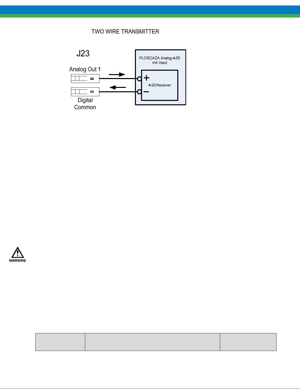
Figure 5-12– Sample Analog Output Connections
5.4 Check Wiring and Close Access Cover
Double-check all of your electrical connections. Pay attention to polarity of all inputs and outputs. Additionally,
insure that all terminals are clamping onto the bare conductor and not on its insulation. Ensure that wires will not be
trapped or pinched when front cover is replaced and secured. Ensure that excess insulation is not removed from the
wires, as this can lead to poor connections or faulty operation.
Close the main access cover and secure the 2 screws.
6. System Configuration
6.1 Overview
Once all electrical connections have been made, your MPC VECTOR is ready for initial setup, calibration,
and operation. All setup occurs using the handheld remote user interface. The following sections detail the
procedures required to complete the MPC VECTOR configuration.
WHEN POWER IS SUPPLIED TO THE UNIT, LINE VOLTAGE IS PRESENT WITHIN THE MPC VECTOR
ENCLOSURE EVEN WHEN THE PUMP MOTOR IS OFF.
During Start-up, it is necessary to run the pump motor. This will cause fluid to discharge from the pump.
You are responsible for safely diverting flow from the pump during start-up and calibration.
6.2 Critical System Configuration Steps
For proper operation of the MPC VECTOR the following parameters and calibrations must be entered and/or
verified (recommended order of setup shown):
Step Number Parameter(s)
27
Reference IOM
Section
Page 34
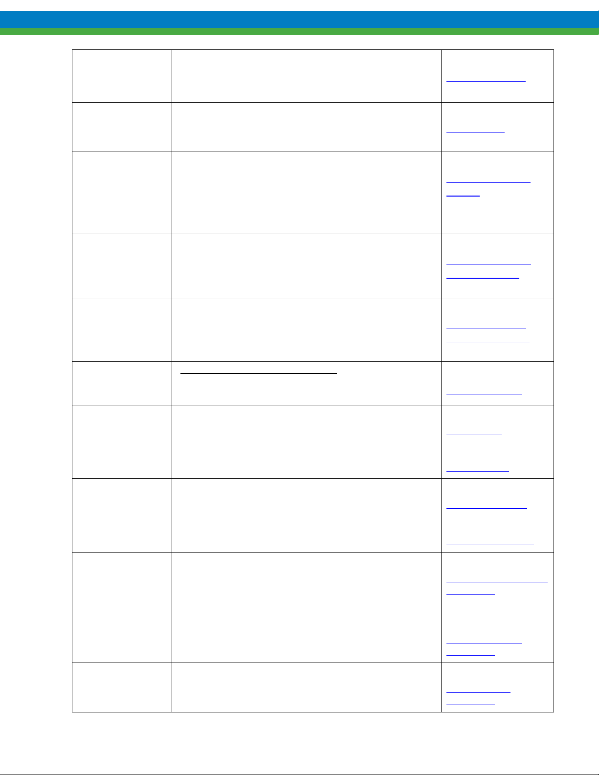
Section 6.3
Step 1 Confirm Handheld Remote Operation
Step 2 Set flow units
Step 3 (Optional)
Set AC Line Voltage
Only for 200-208 and 380-400 VAC installations
Confirm Display
Section 6.5
Flow Display
Units
Section 10
and
AC Input Voltage
Setting
Section 6.6
Step 4 Set t he Pump maximum flow and maximum Speed
Step 5
Step 6 (Optional)
Step 7 (Optional) Activate and Configure Digital Inputs and Outputs
Step 8(Optional) Testing Digital I/O
Motor parameter setup and calibration (Note: pump
rotation may not occur if motor not calibrated)
ONLY IF USING FLOW METER:
flow control, Flow Meter Activation. Test flow meter 420 input
If using closed loop
Setting Max Flow
and Max Speed
Section 11
Motor Parameter
Setup and Tuning
Section 9
Flow Meter Input
Section 7.2 and 7.4
Digital Input
and
Digital Output
Section 7.2.2
Test Digital Inputs
Section 7.4.2
Test Digital Outputs
Section 8.1.1
Open Loop Pump Flow
Calibration
Step 9 Flow calibration
Step 10 (Optional)
Analog Output signal setup, test, and calibration
28
Section 8.1.2
Closed Loop Pump
Flow Scaling and
Calibration
Section 8.1.4
Analog Output
Calibration
Page 35
Section 7.1
Step 11 (Optional)
Analog Input #1 signal setup, test, and calibration
Analog Input Setup
Section 8.1.3
Analog Input
Calibration
6.3 Confirm Display and Keypad Functionality
The example display messages are shown in English for demonstration purposes. If an alternate
language has been set, the text is displayed as a translation of the English version.
Now that you have confirmed that the MPC VECTOR is receiving power, it is necessary to confirm that the display
and keypad are functioning properly. On normal power-up, the following display sequence appears.
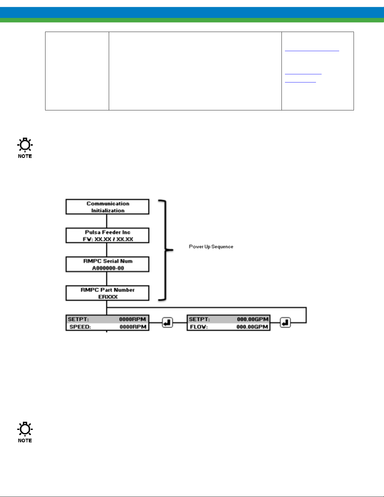
Figure 6-1 MPC VECTOR Display Power Up Sequence
Upon power application the display will show all black squares (approx. 2 seconds). The next four screens show
communication initialization, firmware version, serial number, and part number. These parameters are generally
set at the factory. The firmware screen has the first four digits displayed as the software revision for the MPC
VECTOR control board, and the second four indicate the software revision for the remote board.
The revision numbers should be identical for both units. Unpredictable or unstable operation may
result with mismatched software revisions.
29
Page 36

Please note that it may be necessary to adjust the display contrast. Please refer to Section 8.5 Display Contrast
Adjustment if adjustment is required.
6.4 Motor Parameter Setup
The MPC VECTOR controller interfaces closely with the positive displacement pump motor. The MPC VECTOR
needs to know certain details about the motor (generally found on the motor nameplate) in order to function
properly and optimize performance. End users may have to input or adjust motor parameters before operation. Use
the following as a guide:
If you: Have received your MPC VECTOR and positive displacement pump and motor as a unit from the
factory,
and Your MPC VECTOR to motor wiring distance is less than 25 feet
Then you should not have to perform any motor parameter setup or motor calibration. All parameters and setup
have been completed for you at the factory.
If you: Are using the MPC VECTOR with a motor that did not come from the factory, or
Your MPC VECTOR to motor wiring distance is greater than 25 feet,
or
You are replacing the motor on an existing setup
Then you will have to enter the motor parameters, and you will have to perform a motor calibration procedure.
Please reference Section 11 Motor Parameter Setup and Tuning, before proceeding with operation of your MPC
VECTOR controller.
6.5 Flow Display and Units
The MPC VECTOR will display calibrated pump flow in GPH, LPH, GPM, or LPM on the digital display when
configured for flow control. The motor speed (in RPM) may also be viewed while in flow control. Changes to the
flow units are made in the Menu ->System Setup-> Flow Units Menu. See Section 16 Menu Maps for assistance.
6.6 Setting Max Flow and Max Speed
What is Max Flow?
The value entered into the Max Flow is largely used for display purposes. It limits the flow rates that can be entered
via the handheld unit during normal operations, as well as during analog calibration routines and PulsaGuard
calibration. Internally it is also used in PID calculations.
What should my Max Flow be set to?
Max Flow can vary for a displacement pumps based on the viscosity of the fluid being pumped and the system
pressure. It is recommended that the Max Flow be set 10% higher than pump rated flow at 0PSI
allow for a full range of flow entry values .
What if I try to set my pump to a flow higher than it can actually achieve for my current pressure and viscosity?
. This will
30
Page 37

The pump has internal software protections and validations which prevent the motor from exceeding 1800 RPM
(approximate). Example: If the pump can only achieve 2.5GPM at 1800 RPM for your system configuration and the
flow rate is set to 10GPM, the motor will spin at 1800 RPM and produce 2.5GPM.
What is Max Speed?
Max Speed is the maximum speed that the motor can spin, according to the manufacturer. This is largely unused by
the MPC Vector at the moment and will not affect operations. It is recommended that this value is kept at 1800
RPM.
Setting Max Flow (example shown with GPM units)
1) Begin at the main screen displaying the current flow/speed set point
SETPT 0.00GPM
FLOW 0.00GPM
2) Press the MENU key to access the menus.
-MENU-
CALIBRATION
3) Press the UP or DOWN arrow keys until you get to System Setup.
-MENU-
SYSTEM SETUP
4) Press the ENTER key to access System Setup Menus.
SYSTEM SETUP
STATUS
5) Press the UP key until you see the Information setup option.
SYSTEM SETUP
INFORMATION
6) Press the ENTER key to access the Information screens.
PULSAFEEDER, INC
FW : 1.04/1.04
7) Press the UP or DOWN arrow keys until you see Max flow and Speed displayed.
MAX: 6.00GPM
MAX: 1800RPM
8) Press the Enter key to allow Max Flow to be edited. A blinking cursor will appear
MAX: 6.00GPM
MAX: 1800RPM
9) Press the UP or DOWN arrow keys to manipulate the flow rate until you reach your max flow.
MAX: 8.50GPM
MAX: 1800RPM
10) Press the ENTER key to accept the new Max Flow rate. Note that the blinking cursor has moved to the Max
Speed location.
31
Page 38

11) Press the ENTER key again to save the Max Flow and Max Speed. Note that the blinking cursor should
disappear at this point.
6.7 Wrapping up
Your MPC VECTOR is now commissioned for use. Note that you cannot configure the software in a way that
would damage the MPC VECTOR. Typically, whenever you are about to set a critical value (e.g., Calibrate Flow),
you are always prompted to confirm your change before it takes effect. If you are ever dissatisfied with the
configuration of your MPC VECTOR, you can always return to the Factory Defaults by referring to Section 6.8
Factory Re-Initialization.
MAX: 8.50GPM
MAX: 1800
RPM
MAX: 8.50GPM
MAX: 1800RPM
32
Page 39

6.8 Factory Re-Initialization
Factory Re-initialization is typically not required. When re-initializing your MPC VECTOR, all of the
current system settings and calibration information will be overwritten by the original factory default
settings. The controller must be re-configured and re-calibrated to your specifications.
A Factory Re-initialization should be performed only if there is reason to believe that the MPC VECTOR is
operating abnormally. The condition usually manifests itself with inconsistent or erratic operation – often
associated with meaningless characters on the display, or exaggerated numerical values. Commonly, a user has
entered incorrect parameters, or made changes to the setup of the control.
Once a re-initialization has been performed, all operating parameters should be checked and adjusted or re-entered
as necessary, including maximum flow and rpm, motor parameters, flow and analog signal calibrations, etc.
Factory Re-Initialization:
1. Press the MENU key to access the System Setup Menu
-MENU-
CALIBRATION
2. Press the UP arrow key to display
-MENU-
SYSTEM SETUP
3. Press the ENTER key
SYSTEM SETUP
STATUS
4. Press the UP arrow key twice
SYSTEM SETUP
FACTORY INIT
5. Press the ENTER key
PRESS ENTER
TO FACTORY INIT
6. Press the ENTER key
ARE YOU SURE?
YES=ENTER NO=MENU
7. Pres the ENTER key
RESETTING PUMP
TO FACTORY INIT
33
Page 40

7. Input/Output Setup
Use the “DIGITAL I/O” and “ANALOG I/O” menus to activate and configure the input and output for the functions
required for the application.
Users may also reference Section 16 Menu Maps for additional configuration assistance.
7.1 Analog Input Setup
Two Analog Inputs are provided for the User. Analog Input 1 is used for pump set point (flow or speed pacing)
input. Analog Input 2 is used for systems configured for analog 4-20 mA flow feedback from a user supplied flow
meter.
7.1.1 Analog Input 1 – Set point
Ensure that you have your Analog Input signal connected to the proper location before activating, See Figure 5-8
–I/O Terminal Strip Details (Panel & NEMA4x Shown)– Use Menu->Analog I/O-> Analog Input #1 to activate
the analog input signal function. The menu can be used to set the analog input to either ACTIVE or INACTIVE.
Proceed to Section 8.1.3 Set point Calibration and Range Setup to calibrate your input based upon open or
closed loop operation.
7.1.2 Analog Input 2 – Flow meter Feedback
See Section 9 Flow Meter Input for installation instructions. The flow meter input signal must be configured
properly prior to use. Use Menu ->System Setup-> Flow Meter ->Meter Type->Analog to enable the process
feedback analog input. The flow meter type must be set to “ANALOG” to enable this input. Users may also
reference Section 16 Menu Maps for additional configuration assistance.
7.1.3 Analog Input Testing
The MPC VECTOR allows for testing of the analog inputs with approximate accuracy. Analog input
does not have to be active to use this feature. The user must provide an analog signal from a
PLC/SCADA or 4-20mA transmitter/calibrator to the input under test. See Section 5.3.3.7 Analog Input
Wiring Example for connection. To view the analog input value, proceed to
-> Analog I/O Diagnostics
Once in the Analog Diagnostics Screen the user will see the following:
screen. See Section 16 Menu Maps for navigation if necessary.
System Setup -> Information
AIN1 AIN2 AOUT
X.XX X.XX X.X
AIN1 and AIN2 show the values, in mA’s, currently applied to analog input 1 and 2, respectively.
Changing the value input from the PLC/SCADA, transmitter/calibrator, o r instrumentation (i.e. flow
meter) should be reflected in these two input values. If values do not change be sure to check input
control wiring (signal is polarity sensitive), PLC wiring, and flow meter connections.
34
Page 41

7.2 Digital Input Setup
7.2.1 Multi-purpose Digital Inputs
Each of the 2 Digital INPUTS can be selected as:
Each can be set as normally OPEN or normally CLOSED. For example, if an input is set to ON/OFF and
NORMALLY CLOSED, this means a CLOSED dry contact will activate the pump. A NORMALLY OPEN setup
will give the opposite response. These inputs are to be attached to a dry contact circuit only, apply no voltage to
these inputs.
7.2.2 Testing Digital Inputs
The MPC VECTOR allows for testing of the two digital inputs. The user must provide a dry contact
closure from a PLC/SCADA or a switch to the digital input under test. See Section 5.3.3.6 Digital Input
Example Wiring for connection details. To view the digital input value, proceed to Menu->System
Setup->Information -> Digital I/O Diagnostics. See Section 16 Menu Maps for navigation if necessary.
Once in the Digital Diagnostics Screen the user will see the following
DIN12 DOUT123
11 000
DIN1 and DIN2 show the current values of the digital input on digital input 1 and 2 respectively. A
ZERO represents a closed contact in this screen, an open contact will show a ONE. If values do not
change be sure to check input control wiring.
Inactive
Tank Level Input
Leak Detection (using external device)
Remote ON/OFF Input
Flow verification Input
35
Page 42

7.3 Analog Output Setup
No activation is required for the analog output. The 4-20 mA Analog output is always available at the
corresponding terminals (see Section 5.3.3.8 Analog Output Example Wiring). The analog output follows and is
proportional to percent motor speed. This output must be calibrated for current output (4-20mA) versus percent
speed. See Section 8.1.4 Analog Output Calibration
7.4 Digital Output Setup
7.4.1 Multi-purpose Digital Outputs
Each of the 3 Digital OUTPUTS can be configured to represent:
ON/OFF Status
AUTO/MAN Status
Leak Detected
Alarm Indicator
Tank Level Status
Each output can be set as NORMALLY OPEN (N.O.) or NORMALLY CLOSED (N.C.). For example, if an output
is set to ON/OFF status and NORMALLY CLOSED, this means that when the motor is running (indicator lamp is
ON) the output will be CLOSED. A NORMALLY OPEN setup will give the opposite response.
Digital output circuits are transistor based and limited to 24 VDC maximum (500 mA current limit per output), see
Section 5.3.3.5 Digital Output Wiring Example (Open Collector/Drain), and Section 13 Specifications for more
information.
7.4.2 Testing Digital Outputs
The MPC VECTOR allows the user to test the three (3) digital outputs. To manually control the digital
output values, proceed to Menu->System Setup – Information – Digital I/O Diagnostics. See the Section 16
Menu Map for navigation if necessary. The user can select the desired output by pressing the ENTER
key. Once an output is selected, the user can change the output by pressing UP/DOWN. Doing so will
activate and deactivate the selected output.
Once in the Digital Diagnostics Screen the user will see the following
DIN12 DOUT123
11 101
DOUT123 shows whether the digital output is activated (1) or deactivated (0) on digital outputs 1, 2, and
3, respectively. The example above shows Digital Outputs 1 and 3 activated and 2 deactivated. The
user has selected digital output 1 for activation/deactivation.
36
Page 43

This page is intentionally left blank
37
Page 44
8. Calibrations
YOUR MPC VECTOR IS NOT FACTORY CALIBRATED AS THE CALIBRATIONS ARE SYSTEM DEPENDENT AND
FLOW METER DEPENDENT
INSTALLED IN YOUR SYSTEM PRIOR TO USE
DAMAGE TO SYSTEM COMPONENTS
As a convention in this manual:
“WET” calibration procedures will refer to those that require normal operating conditions, for example:
the pump running with fluid
an electrical signal input (i.e. 4-20mA calibrator) provided at the appropriate terminals.
“DRY” calibration procedures are run under non-operational conditions, and often do not require the pump
to run or that a specific input signal be present.
Some of the calibration routines may be performed either way. Note any system requirements listed for each
routine.
. YOU MUST ALWAYS PERFORM A CALIBRATION WITH THE MPC VECTOR
. FAILURE TO PROPERLY CALIBRATE THE UNIT MAY RESULT IN
.
8.1 Pump Flow Calibration
The MPC Vector uses a two point pump flow calibration method. This calibration method is used for both open
(speed based) and closed loop flow control (flow meter based) systems. For details on theory of operation, refer to
Section 1.2.5 Control Modes. Refer to Section 16 Menu Maps for key press sequences.
8.1.1 Open Loop Pump Flow Calibration
Open loop speed based flow calibration will need two flow rate points and require two drawdown intervals
(wet cal only), one at a high speed (max speed recommended) and another at low speed (full turndown
recommended). These pump RPM points can be adjusted for flow within your pumps flow rate. In order to
use the full speed range (default 10:1 turndown) use the maximum allowable speed range based upon motor
turndown.
Note: The following calibration example shows an example pump with measured flow rates of 25 GPH at
1800 RPM and 2.5 GPH at 180 RPM (maximum turndown utilized). These will be the two calibration
points used by the system, once calibration is complete.
Below is a flow Calibration Table to aid as an example in recording your two point pump flow information.
Speed
(RPM)
Point 1 1800 0.416 60 sec 25 GPH
Point 2 180 0.0416 60 sec 2.5 GPH
Your Point 1
Your Point 2
For GPH (Gallons Per Hour)
:
Volume
Delivered
(GAL)
Time
Elapsed
(seconds)
Calculated
Flow Rate
3600/
38
Page 45
For GPM (Gallons Per Minute)
:
60/
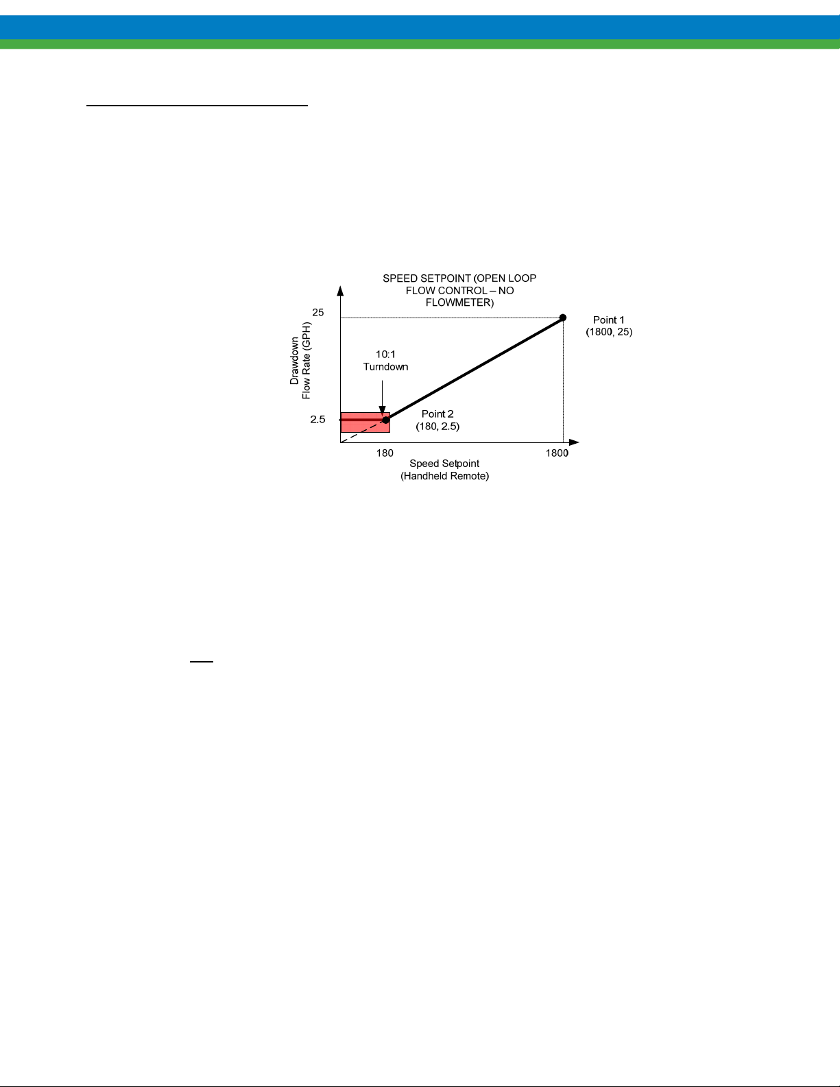
Shown below is the two point calibration curve for the example data presented in the above table. These
values represent the speed-to-flow characterization of your pump. The two speed values, 180 RPM (10%)
and 1800 RPM (100%), will correspond to 2.5 and 25 GPH, respectively for this pump. The speed values
can be used for set point input calibration, see Section 8.1.3 Set point Calibration and Range Setup .
Figure 8-1 Open Loop Speed-to-Flow Calibration Flow Curve
The default drawdown interval is 60 seconds although the user may terminate for shorter intervals. You
will be requested to enter your calculated flow rate at the end of each drawdown period.
8.1.1.1 Open Loop Dry Flow Calibration
The open loop Dry Flow Calibration routine does not require the pump to run. Instead, the user must input 2 known
flow rate versus speed points. These points may come from previous calibrations or from a pump data sheet. The
user will be prompted for these values. This process can be used for fine adjustment of flow rate display, or in
situations where it is not possible or not safe to run the pump during calibration.
Note: A good default entry for pump dry flow is pump maximum rated flow at 1800 RPM and one-tenth of
pump maximum flow at maximum speed turn down of 180 RPM.
Proceed with the following steps from the handheld remote:
1. Press the MENU key to access the Calibration Menu.
CALIBRATION
-MENU-
2. Press the ENTER key to access Pump Flow Calibration screen.
CALIBRATION
PUMP FLOW
3. Press the ENTER key to access Dry Pump Flow Calibration screen.
39
Page 46

PUMP FLOW
DRY CAL
4. Press ENTER to edit the high speed (“HI SPEED” where the default = 1800 RPM) and flow rate calibration
point.
HI SPEED: 1800RPM
FLOW: 25.00GPH
5. Using the UP/DOWN/ENTER keys enter the calibration speed and flow points.
6. Press the ENTER key to accept the calibration flow rate and proceed to the low speed calibration point.
LOWSPEED: 180 RPM
FLOW: 2.50 GPH
7. Press ENTER to edit the low speed (default=180 RPM) and flow rate calibration point.
8. Using the UP/DOWN/ENTER keys enter the calibration speed and flow points.
9. Press the ENTER key to accept the calibration flow rate and save the two point calibration.
10. At this point, the system will check the dry calibration values, and if the values are acceptable will complete the
calibration.
PUMP FLOW
CALIBRATED
8.1.1.2 Open Loop Wet Flow Calibration
The Open Loop Wet Flow Calibration routine requires the user to run the pump and record the corresponding flow
at two known pump speeds.
Before proceeding, ensure the following:
That it is safe to run the pump and dispense liquid into the system.
That the pump is fully primed with the product.
That the calibration column has enough fluid for the dispensing time to prevent a run dry
scenario.
That you are prepared to record the volume and time interval for 2 draw downs.
Then proceed with the following steps from the handheld remote:
1. Press the MENU key to access the Calibration Menu.
CALIBRATION
-MENU-
2. Press the ENTER key to access Pump Flow Calibration screen.
CALIBRATION
PUMP FLOW
40
Page 47
3. Press the ENTER key to access Wet Pump Flow Calibration screen.
PUMP FLOW
WET CAL
4. Press the ENTER key to begin Flow Calibration
SET MOTOR SPEED
HIGH: 1800 RPM
5. Using the UP and/or DOWN arrow keys adjust the motor speed to a high flow speed setpoint. The speed set is the
high speed calibration point for the MPC VECTOR that you will measure flow at.
6. Press the ENTER key to accept the calibration speed.
PRESS ENTER TO
START MOTOR
THE MOTOR WILL START WHEN THE ENTER KEY IS PRESSED. MAKE SURE THAT YOUR SYSTEM IS
PREPARED FOR OPERATIONS BEFORE STARTING THE MOTOR
.
7. Press the ENTER key to start the motor. The system advances to the draw down interval count down screen.
The default interval will be 60 seconds. At any time, pressing the ENTER key will take the user immediately to
the next screen. This allows for shorter drawdowns using the ENTER key. All other keys abort the calibration.
RUNNING 60 SECS** (WILL COUNT DOWN)
MOTOR: 1800 RPM
**60 SECONDS WILL ELAPSE BY DEFAULT
8. Based upon your drawdown interval and volume dispensed, calculate the high speed calibration flow rate value.
Using the UP and/or DOWN arrow keys adjust the flow to your calculated value.
FLOW AT 1800RPM
FLOW: 25.00GPH
9. Press the ENTER key to accept the calibration flow rate and proceed to the low speed calibration point.
10. Using the UP and/or DOWN arrow keys adjust the motor speed to an approximate low speed setpoint. This speed
is the low speed calibration point for the MPC VECTOR that you will measure flow at.
SET MOTOR SPEED
LOW: 180 RPM
11. Press the ENTER key to accept the calibration speed.
PRESS ENTER TO
START MOTOR
THE MOTOR WILL START WHEN THE ENTER KEY IS PRESSED. MAKE SURE THAT YOUR SYSTEM IS
PREPARED FOR OPERATIONS BEFORE STARTING THE MOTOR
.
41
Page 48

12. Press the ENTER key to start the motor and advance to the draw down interval count down screen. The default
interval will be 60 seconds. Pressing the ENTER key will take the user immediately to the next screen. Shorter
drawdowns are available using the ENTER key. All other keys abort the calibration.
RUNNING 60 SECS**
MOTOR: 180 RPM
**60 SECONDS WILL ELAPSE BY DEFAULT
THE MOTOR WILL START WHEN THE ENTER KEY IS PRESSED. MAKE SURE THAT YOUR SYSTEM IS
PREPARED FOR OPERATIONS BEFORE STARTING THE MOTOR
13. Based upon your drawdown interval and volume dispensed, calculate the low speed calibration flow rate value.
Using the UP and/or DOWN arrow keys adjust the flow to your calculated value.
.
FLOW AT 180 RPM
FLOW: 2.50 GPH
14. Press the ENTER key to accept the low speed calibration flow rate.
15. At this point,the system will check the calibration values, and if the values are acceptable will complete the
calibration.
PUMP FLOW
CALIBRATED
8.1.2 Closed Loop Pump Flow Scaling and Calibration
NOTE: Be sure to set flow meter to active. See Section 7.1.2 Analog Input 2 – Flow meter Feedback
Closed loop flow control calibration and scaling requires the following:
Two calibration speeds of user preference, nominally full range (1800 RPM to high speed turndown)
A calibrated flow meter with a flow output signal providing flow feedback, a 4-20mA current signal.
Two flows associated with two these current feedback values (i.e. two calibration points).
o WET flows come from normal running conditions at two speeds.
o DRY flows come from the flow meter ZERO AND SPAN settings
The DRY calibration is the default method - if you know your flow meter ZERO AND SPAN flow rate
Example: If you have a pump with a rated capacity of 20 GPH, configure your flow meter span for 25.0 GPH at
20.0 mA and 0.00 GPH at 4.00 mA, then proceed to the closed loop dry flow calibration and enter these two flow
versus current calibration values. See Figure 8-2 Example Flow Meter Current Output vs. Flow Rate Curve below
as an example of setting your calibration points.
Note: Be sure to set your flow meters span and size your flow meter slightly higher than the rated capacity
identified on the pumps nameplate.
42
Page 49
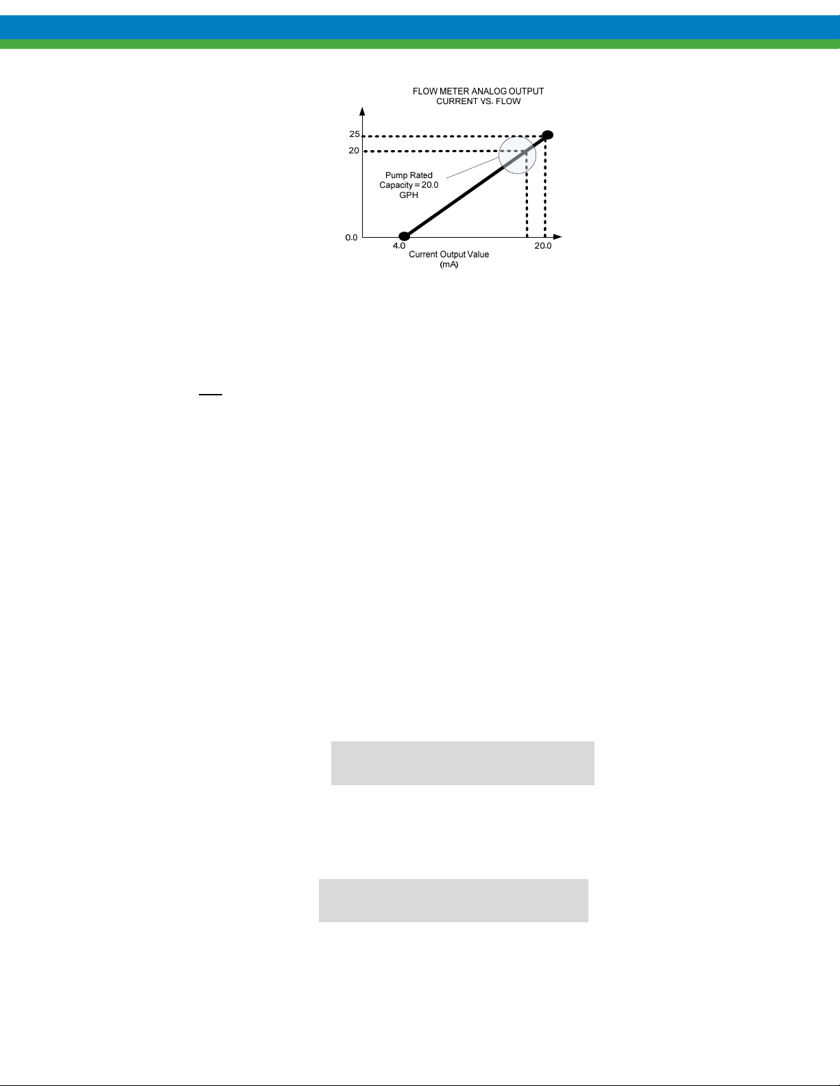
Pump Flow (GPH)
Figure 8-2 Example Flow Meter Current Output vs. Flow Rate Curve
8.1.2.1 Closed Loop Dry Flow Calibration
The closed loop Dry Flow Calibration routine does not require the pump to run. Instead, the user must input 2
known flow meter flow rates versus current output points. The user will be prompted for these values. This process
can be used when it is not possible or not safe to run the pump during calibration.
Proceed with the following steps from the handheld remote:
1. Press the MENU key to access the Calibration Menu.
-MENU-
CALIBRATION
2. Press the ENTER key to access Pump Flow Calibration screen.
CALIBRATION
PUMP FLOW
3. Press the ENTER key to access Dry Pump Flow Calibration screen.
PUMP FLOW
DRY CAL
4. Press ENTER to edit the high speed/flow mA reading and corresponding flow rate calibration point.
MAX METER: 20.0MA
FLOW: 30.00GPH
5. Using the UP/DOWN/ENTER keys enter the calibration mA and flow rate point.
6. After setting the high flow calibration point, press the ENTER key to accept the calibration point and proceed to
the low flow calibration point.
MIN METER: 4.0 MA
FLOW: 0.0 GPH
7. Press ENTER to edit the low speed/flow mA reading and corresponding flow rate calibration point.
8. Using the UP/DOWN/ENTER keys enter the calibration mA and flow points.
43
Page 50
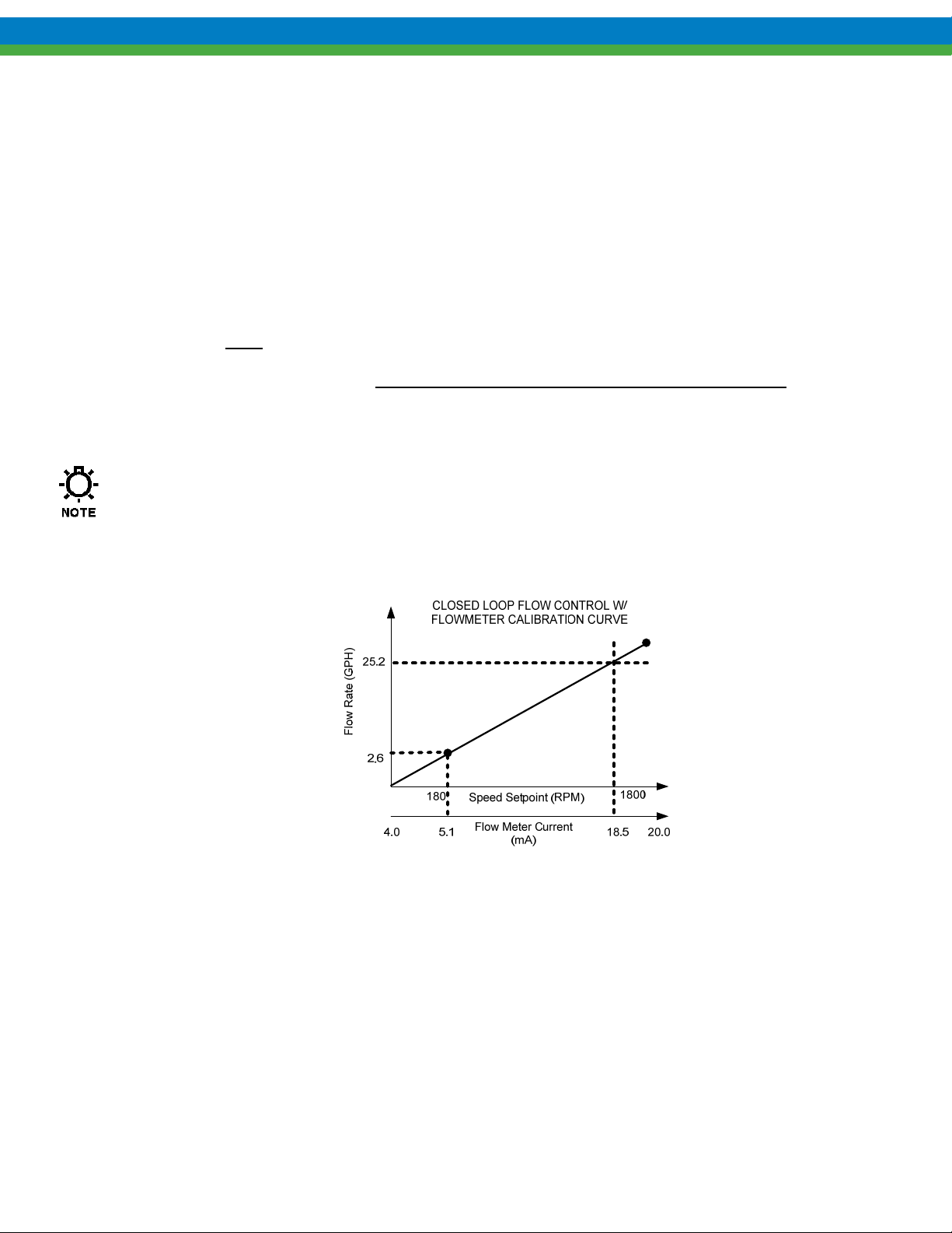
9. After setting the low speed calibration point, press the ENTER key to accept the calibration flow rate and save the
two point calibration.
10. At this point, the system will check the dry calibration values, and if the values are acceptable will complete the
calibration.
PUMP FLOW
CALIBRATED
8.1.2.2 Closed Loop WET Flow Calibration
The closed loop WET flow calibration routine will require the user to run the pump and provide system flow at a
user selected low and high speed. The controller will monitor the current from the flow meter and store it for both
high and low flow readings. The user must provide the corresponding meter flow rate readout
point calibration. Note: The flow meter output current must be configured to be within the 4-20 mA range over the
full speed/flow range of the pump. See your flow meter’s IOM to set analog 4-20 mA output range versus the flow
rate measured.
To optimize feedback, it is best to set your flow meter 4mA to 0 flow and 20mA to a value slightly higher (10-
20% or so) than your pumps rated capacity. This allows the user a full range of flow set points as well as
giving the MPC VECTOR the best possible 4-20mA analog resolution.
, providing a two
Shown below is the speed, flow, and current graph for the two point closed loop calibration.
Figure 8-3 Closed Loop Flow Control WET Calibration Curve
Ensure the following:
That your flow meter is providing output to Analog Input 2.
That your system is set up for flow meter/closed loop operation. (See section 5.3.3.7.1 Flow
Meter (Analog Input 2) i.e. flow meter set to analog)
That it is safe to run the pump and dispense liquid into the system.
That the pump is fully primed with the product.
That you are prepared to read the flow rate from your meter. Then proceed with the
following steps from the handheld remote:
44
Page 51

1. Press the MENU key to access the Calibration Menu.
-MENU-
CALIBRATION
2. Press the ENTER key to access Pump Flow Calibration screen.
CALIBRATION
PUMP FLOW
3. Press the ENTER key to access Wet Pump Flow Calibration screen.
PUMP FLOW
WET CAL
4. Press the ENTER key to begin Flow Calibration
SET MOTOR SPEED
HIGH: 1800 RPM
5. Using the UP and/or DOWN arrow keys adjust the motor speed to an approximate high speed setpoint. This
speed is the high speed calibration point for the MPC MPC VECTOR that you will measure flow at.
6. Press the ENTER key to accept the calibration speed.
PRESS ENTER TO
START MOTOR
THE MOTOR WILL START WHEN THE ENTER KEY IS PRESSED. MAKE SURE THAT YOUR SYSTEM IS
PREPARED FOR OPERATIONS BEFORE STARTING THE MOTOR
.
7. Press the ENTER key to start the motor and advance to the calibration interval count down screen. The default
interval will be 60 seconds. Pressing the ENTER key will take the user immediately to the next screen. Shorter
drawdowns are available by using the ENTER key to terminate at the desired interval. All other keys abort the
calibration. Observe the final flow rate on your flow meter at the end of the interval as it must be entered in the
next step.
RUNNING 60 SECS**
METER: 18.5 MA
**60 SECONDS WILL ELAPSE BY DEFAULT
8. Using the UP and/or DOWN arrow keys adjust the flow to your flow meter’s displayed flow rate value at the end
of the calibration interval.
FLOW AT 18.5 MA
FLOW: 25.2 GPH
9. Press the ENTER key to accept the calibration flow rate and proceed to the low flow calibration point.
10. Using the UP and/or DOWN arrow keys adjust the motor speed to an approximate low speed setpoint. This speed
is the low speed calibration point for the MPC VECTOR. This speed will produce a low flow and provide a flow
feedback signal to the controller. At this speed you will monitor flow rate from the flow meter and enter it via the
handheld unit.
45
Page 52

SET MOTOR SPEED
LOW: 180 RPM
11. Press the ENTER key to accept the calibration speed.
PRESS ENTER TO
START MOTOR
THE MOTOR WILL START WHEN THE ENTER KEY IS PRESSED. MAKE SURE THAT YOUR SYSTEM IS
PREPARED FOR OPERATIONS BEFORE STARTING THE MOTOR
12. Press the ENTER key to start the motor and advance to the calibration interval count down screen. The default
interval will be 60 seconds. Pressing the ENTER key will terminate the calibration interval and take the user
immediately to the next screen. All other keys abort the calibration.
.
RUNNING 60 SECS**
METER: 5.1 MA
**60 SECONDS WILL ELAPSE BY DEFAULT
13. Based upon your drawdown interval and volume dispensed, observe the final flow rate on your flow meter at the
end of the interval as it must be entered in the next step.
14. Using the UP and/or DOWN arrow keys adjust the flow to your observed value.
FLOW AT 5.1 MA
FLOW: 2.6 GPH
15. Press the ENTER key to accept the low speed calibration flow rate.
16. At this point,the system will check the calibration values, and if the values are acceptable will complete the
calibration.
PUMP FLOW
CALIBRATED
8.1.3 Set point Calibration and Range Setup
Set point calibration and range setup will allow the user to scale and calibrate the 4-20 mA current input for speed
or flow, depending upon whether the system is open or closed loop. This calibration and setting of range can be
done wet or dry. To perform a Wet
generating the full range (4-20 mA) of current input signals. Dry
To perform a Wet
Input #1. Refer to Section 5.3.3.7.2 Set point (Analog Input 1).
set point calibration, you must first correctly wire an external current signal source, to Analog
calibration the signal-generating device must be active and capable of
calibration requires no input signal.
Set point Range/Calibration for Open Loop Systems (Speed Control)
Set points, applied remotely to Analog Input #1 are used to adjust motor speed in RPM
configured for open loop speed control. In the example shown below the user has scaled/calibrated the 4ma signal
to correspond to 180 RPM and 20 mA to correspond to 1800 RPM. This scaling configuration uses the full range of
pump motor speed available and maximizes the available pump flow rates.
46
when the system is
Page 53
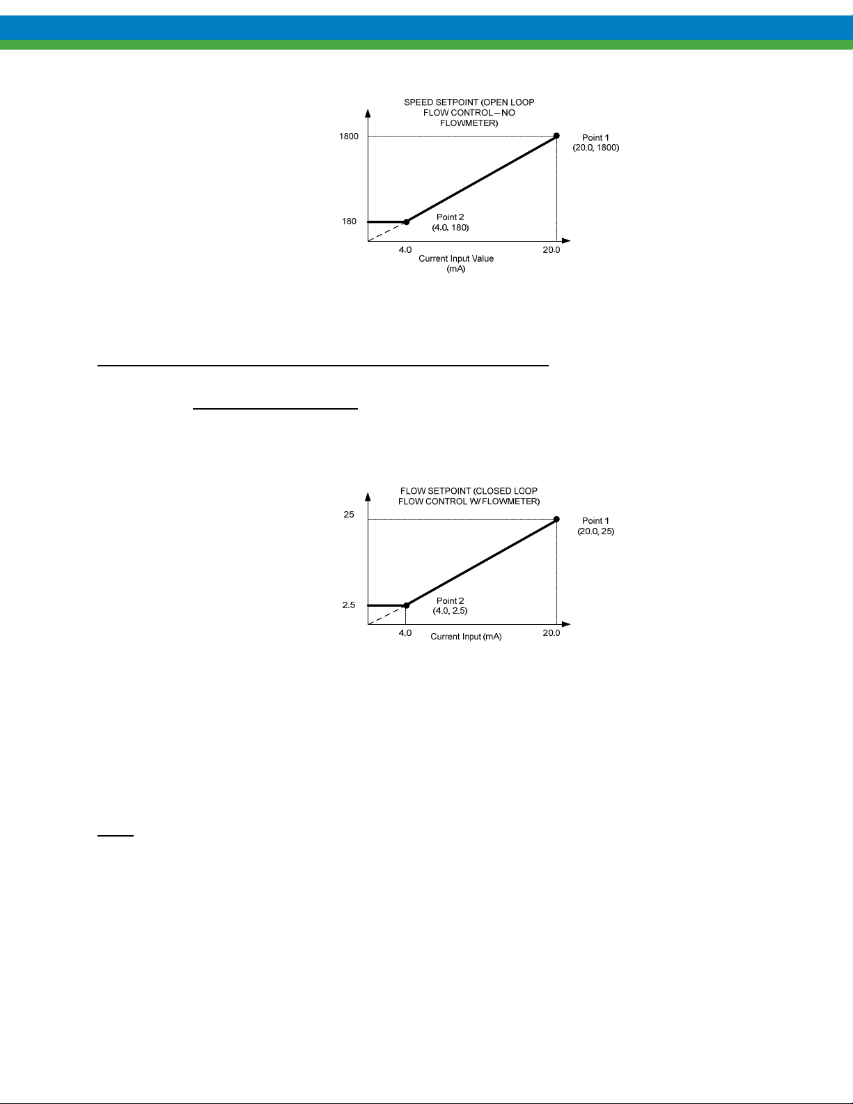
Speed (RPM)
Commanded Pump Motor
Figure 8-4 Set point Input 4-20 mA Scaling/Calibration (Speed)
Set point Range/Calibration for Closed Loop Systems (Flow Control)
If your system is configured for closed loop flow control (e.g., flow meter feedback), the applied set point input is
used to control the flow rate of the pump
signal to correspond to 2.5 GPH and 20 mA to correspond to 25 GPH. This scaling configuration uses the full range
of flow rates available and maximizes the available pump flow rates.
. In the example shown below, the user has scaled/calibrated the 4mA
Commanded
Flow Rate (GPH)
Figure 8-5 Set point Input4-20 Scaling/Calibration (Flow)
If the MPC VECTOR is configured for Closed Loop Flow Control the displays below will show “flow” and scale
the 4-20 mA to flow rate. The displays below are currently showing pump flow.
If the MPC VECTOR is configured for Open Loop Flow Control the displays below will show “speed” and scale
the 4-20 mA to motor RPM.
The set point input calibration shown below is for closed loop flow control.
Note:
8.1.3.1 “WET” Set point Input Calibration (with a field signal)
1. The starting display will be:
SETPT XX.XXX
FLOW XX.XXX
2. Press the MENU key
47
Page 54

-MENU-
CALIBRATION
3. Press the ENTER key
CALIBRATION
PUMP FLOW
4. Press the DOWN arrow key once, to access the analog input calibration
CALIBRATION
ANALOG INPUT
5. Press the ENTER key
ANALOG INPUT
WET CAL
6. Press the ENTER key
APPLY MAX MA
ENTER TO START
7. Apply your desired maximum mA control signal to the MPC VECTOR (usually 20 mA)
8. Press the ENTER key
MAX SETPT 20.0MA
FLOW 25.00GPH
(The mA value will be equal to your signal source/calibrator level)
(The lower line shows the flow or speed set point the MPC VECTOR will use for this signal value)
9. Press the UP and DOWN arrow keys to change the Speed/Flow corresponding to the Analog Input Value.
10. Press the ENTER key once more to accept the calibration value
APPLY MIN MA
ENTER TO START
11. Apply your desired minimum mA control signal to the MPC VECTOR (usually 4 mA)
12. Press the ENTER key
MIN SETPT 4.0MA
FLOW 2.50GPH
(The mA value will be equal to your input signal level)
(The lower line shows the setting the MPC VECTOR will use for this signal value)
13. Press the UP and DOWN arrows to adjust the Speed/Flow corresponding to the Analog Input value.
14. Press the ENTER key once more to accept the calibration value
ANALOG INPUT
CALIBRATED
15. Analog input signal calibration is complete
16. Press the MENU key three times to exit back to the main operating screen.
48
Page 55

If you receive the following message:
CURRENT DELTA
OUT OF RANGE
This indicates that there is not a wide enough range between your maximum and minimum analog signals. The
minimum signal range is 3 mA. The most likely source of this error is the user did not change the value of the
incoming analog signal when moving from the MIN calibration to the MAX calibration.
The analog input signal calibration procedure should be performed again, ensuring that a minimum
of 3 mA difference exsists between the MIN and MAX signal levels.
49
Page 56

8.1.3.2 “DRY” Set point Input Calibration (keypad only, no signal present)
1. The starting display will be:
SETPT XX.XXX
FLOW XX.XXX
2. Press the MENU key
-MENU-
CALIBRATION
3. Press the ENTER key
CALIBRATION
PUMP FLOW
4. Press the UP arrow key twice, to access the analog input calibration
CALIBRATION
ANALOG INPUT
5. Press the ENTER key
ANALOG INPUT
WET CAL
6. Press the UP or DOWN key
ANALOG INPUT
DRY CAL
7. Press the ENTER key to access the DRY Pump Flow Calibration routine for ANALOG Flow Meters. A blinking
cursor will show you that you are adjusting the Current (mA).
MAX SETPT 0.0MA
FLOW: 0.00GPM
8. Press the UP and/or DOWN keys to adjust the Current set point.
MAX SETPT 20.0MA
FLOW: 0.00GPM
9. Press the ENTER key to accept this setpoint. The Cursor will now blink on the second line, indicating that the
flow rate at 20.0 mA is the active field. Press the UP and/or DOWN keys to adjust the Flow setpoint.
MIN SETPT 4.0MA
FLOW: 0.00GPM
10. Press the ENTER key to access the MIN setpoint values. The cursor will blink on the top line indicating
that the Current setpoint may be adjusted.
MAX SETPT 16.0MA
FLOW: 4.00GPM
11. Press the UP and/or DOWN arrow keys to adjust the Max Current setpoint.
MAX SETPT 20.0MA
FLOW: 4.00GPM
50
Page 57
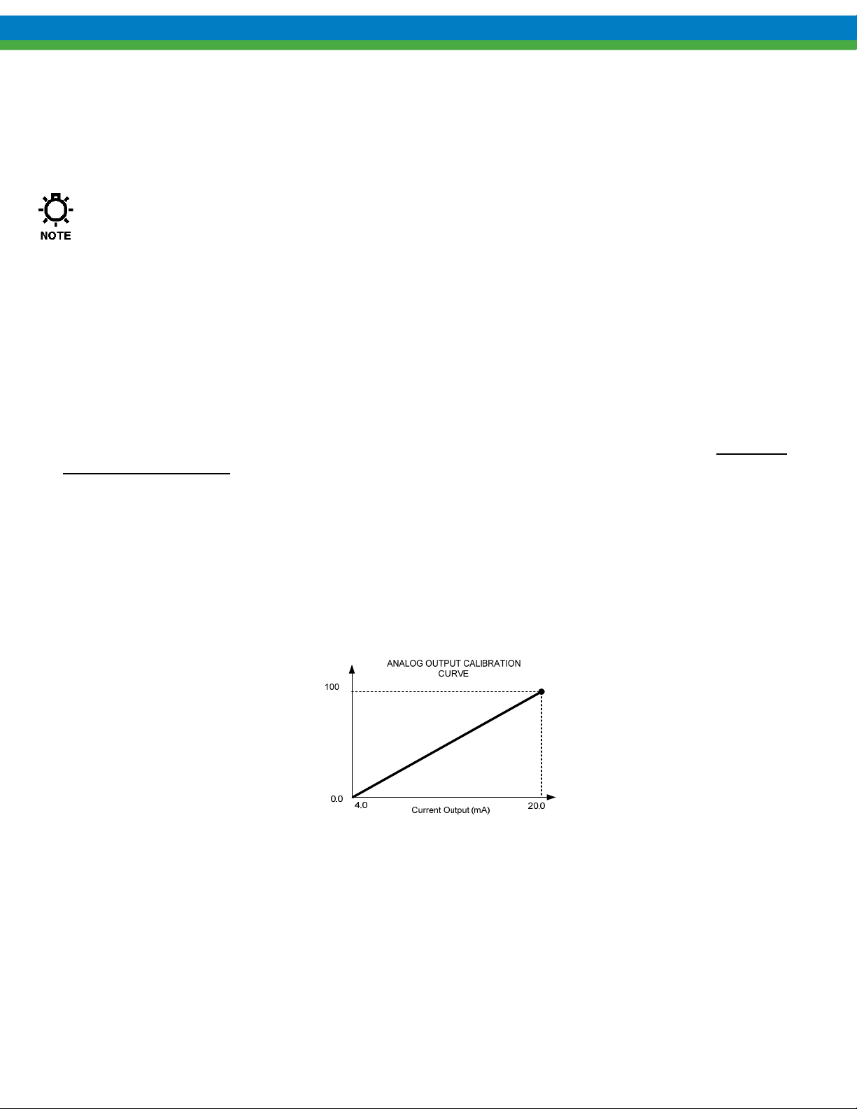
Press ENTER to accept the Current Setpoint. The cursor will blink on the bottom line indicating that the Flow
setpoint may be adjusted.
12. Press the UP and/or DOWN arrow keys to adjust the Max Flow setpoint.
MAX SETPT 20.0MA
FLOW: 5.92GPM
You may back out of the DRY calibration routine at any point up to now without saving any
calibration settings by pressing the MENU key several times.
Press the ENTER key to save the new Analog Calibration values. Upon completion of Calibration you should see the
following screen.
ANALOG INPUT
CALIBRATED
13. Press the MENU key several times to return to Operation Mode.
8.1.4 Analog Output Calibration
The analog output calibration routine maps the motor speed as % of maximum motor speed configured in Section 6.5
Flow Display and Units
The MPC VECTOR will display calibrated pump flow in GPH, LPH, GPM, or LPM on the digital display
when configured for flow control. The motor speed (in RPM) may also be viewed while in flow control.
Changes to the flow units are made in the Menu ->System Setup-> Flow Units Menu. See Section 16 Menu
Maps for assistance.
Setting Max Flow and Max Speed of the MPC VECTOR to a 4-20mA output signal. The output signal is NOT
proportional to pump flow. If a 4-20mA signal representing flow is required it must be obtained by splitting the flow
meter output signal.
MOTOR PERCENT SPEED
Figure 8-6 Analog Output Scaling/Calibration Curve
1. The starting display will be:
SETPT XX.XXX
FLOW XX.XXX
2. Press the MENU key
-MENU-
51
Page 58

CALIBRATION
3. Press the ENTER key
CALIBRATION
PUMP FLOW
4. Press the UP ARROW key to access the analog output calibration
CALIBRATED
ANALOG OUTPUT
5. Press the ENTER key
SET 0% SPEED TO
4.0 MA
You may measure the output of the analog output during the calibration procedure. Likewise during the
calibration the analog output is active and should be seen by your PLC/SCADA system.
6. Use the UP and DOWN arrow keys to adjust the output signal as required. The value displayed on the
screen may not match the actual output signal and is for visual reference only.
7. Press the ENTER key once more to accept the calibration
SET 100% SPEED TO
20.0 MA
8. Use the UP and DOWN arrow keys to adjust as in step 6 above
9. Press the ENTER key once more to accept the calibration value
ANALOG OUTPUT
CALIBRATED
10. Analog output signal calibration is complete
11. Press the MENU key three times to exit back to the main operating screen
If you receive the following message:
CURRENT DELTA
OUT OF RANGE
This indicates that the output current for 0% speed has been set greater than or equal to the output current setting for
100% speed. Repeat the process and ensure that the 0% calibrated signal is set to a value lower than the 100%
calibrated signal.
8.2 PulsaGuard Pump Protection
PulsaGuard is designed to turn your pump off when running in dangerous conditions. These conditions are user
configurable and can be easily modified to meet each application.
52
Page 59

8.3 Closed Loop Flow PulsaGuard Protection
When a flow meter is installed in the system, PulsaGuard will turn off your motor if the present system flow rate is
below a user desired low flow threshold for more than 10 seconds. This will protect the pump in under-loaded or
overloaded conditions, which would cause the flow to be reduced below the user’s acceptable threshold limit.
The MPC VECTOR will also trigger an alarm condition if the flow set point cannot be reached for some reason. This
alarm will be displayed on the MPC VECTOR display but will not shut the motor off.
8.4 Open Loop Speed PulsaGuard Protection
If the MPC VECTOR is operating without flow meter feedback PulsaGuard can read the motor current and shut off
the pump if the current drops below the shut off level and stays under that level for 10 seconds, effectively protecting
equipment from under-loaded conditions.
The PulsaGuard pump protection may be enabled and disabled as desired from the System Setup menus. Note that
once a PulsaGuard calibration is performed the pump protection is automatically enabled, you will not have to
manually enable it.
8.4.1 PulsaGuard Calibration - Closed Loop Flow Control
1. The starting display will be:
SETPT XX.XXX
FLOW XX.XXX
2. Press the MENU key
-MENU-
CALIBRATION
3. Press the ENTER key
CALIBRATION
PUMP FLOW
4. Press the UP key
CALIBRATION
PULSAGUARD
5. Press the ENTER key
MIN SETPOINT
SETPT: 0.00GPM
6. Using the UP and DOWN arrow keys set the low flow setpoint
MIN SETPOINT
SETPT: 0.50GPM
53
Page 60

7. Press the ENTER key to complete the PulsaGuard Calibration.
PULSAGUARD
CALIBRATED
8.4.2 PulsaGuard Calibrations- Open Loop Speed Control
PulsaGuard may be calibrated WET or DRY. A WET calibration requires that the user simulate underloaded
conditions.
Follow Steps 1-4 above. You should see the following screen
CALIBRATION
PULSAGUARD
5. Press the ENTER key.
PULSAGUARD
WET CAL
WET CALIBRATION:
6. Press the ENTER key again to access the WET calibration routine.
START MOTOR
YES=ENTR NO=MENU
7. Run the pump to meet desired low setpoint conditions. You may adjust the speed of the motor using the UP
and DOWN arrow keys. The output current of the motor will be displayed on the screen. In the example
shown below, a RPM of 600 RPM creates a motor current draw of 2.0 amps. If the motor becomes
underloaded the current will drop below this value, creating a PulsaGuard alarm.
MIN SETPT 2.0A
SPEED: 600RPM
8. Once the MPC MPC VECTOR has reached the desired low current setpoint, press the ENTER key.
PULSAGUARD
CALIBRATED
9. PulsaGuard Pump Protection is now calibrated and enabled.
DRY CALIBRATION:
10. Press the UP key.
PULSAGUARD
DRY CAL
11. Press the ENTER key.
MIN SETPOINT
SETPT: 0.0A
54
Page 61

12. Use the UP and DOWN keys to adjust the current setpoint.
MIN SETPOINT
SETPT: 2.0A
13. Press the ENTER key to accept the calibration value.
14. PulsaGuard Pump Protection is now calibrated and enabled.
8.5 Display Contrast Adjustment
Should adjustment of the contrast level of the remote handheld display become necessary, use the following
procedure while in the normal operating mode.
To increase contrast, press and hold at the same time.
PULSAGUARD
CALIBRATED
To decrease contrast, press and hold at the same time.
55
Page 62

8.6 Tuning the Control Algorithm
This option should only be used by control systems engineers who are familiar with tuning PID loops.
not intended for the casual user. Changing these values may result in the system oscillating without settling
on the set point or never reaching the set point at all. See Section 21, Appendix 2 for more information and
theory on PID control.
The MPC VECTOR allows users to tune the motor control algorithm to speed up or slow down the MPC VECTOR
set point response time. This is done by adjusting the PID Controller parameter coefficients.
The user may adjust the Proportional coefficient, k
, independently. The user may also view and modify the sampling period of the control loop, ts.
k
d
Modifying the PID coefficients
1. The starting display will be:
, the Integration coefficient, ki, and the Derivative coefficient,
p
This is
SETPT XX.XXX
FLOW XX.XXX
2. Press the MENU key.
-MENU-
CALIBRATION
3. Press the UP arrow key.
4. Press the ENTER key.
5. Press the DOWN.
6. Press the ENTER key.
7. Press the ENTER key.
-MENU-
SYSTEM SETUP
SYSTEM SETUP
STATUS
SYSTEM SETUP
PID PARAMETERS
PID PARAMETERS
COEFFICIENTS
PROPORTIONAL
X.XXX
56
Page 63

8. Press the UP and/or DOWN keys to adjust, k
.
p
PROPORTIONAL
0.100
9. Press the ENTER key.
INTEGRAL
X.XXX
10. Press the UP and/or DOWN keys to adjust, ki.
INTEGRAL
0.050
11. Press the ENTER key.
DERIVATIVE
X.XXX
12. Press the UP and/or DOWN keys to adjust, kd.
DERIVATIVE
0.050
13. You may back out without saving the new PID coefficients at this point by hitting the MENU key several
times to return to the first screen. If you want to save the changes press the ENTER key.
PID PARAMETERS
COEFFICIENTS
14. The new PID coefficients have been set.
57
Page 64

Modifying the Sampling Interval, when Flow Meter feedback is used
1. The starting display will be:
SETPT XX.XXX
FLOW XX.XXX
2. Press the MENU key.
-MENU-
CALIBRATION
3. Press the UP arrow key.
-MENU-
SYSTEM SETUP
4. Press the ENTER key.
SYSTEM SETUP
STATUS
5. Press the DOWN key until you get to the PID screen.
SYSTEM SETUP
PID PARAMETERS
6. Press the ENTER key.
PID PARAMETERS
COEFFICIENTS
7. Press the UP arrow key.
PID PARAMETERS
SAMPLING PERIOD
8. Press the ENTER key.
SAMPLING PERIOD
PERIOD: XXXMS
9. Press the UP and/or DOWN arrows to adjust the sampling period, ts. (Note: value is entered in milli-
seconds e.g., 1000 milliseconds = 1 second)
SAMPLING PERIOD
PERIOD: XXXMS
10. Press the ENTER key to accept the new sampling period
PID PARAMETERS
SAMPLING PERIOD
11. The new PID sampling period has been set.
58
Page 65
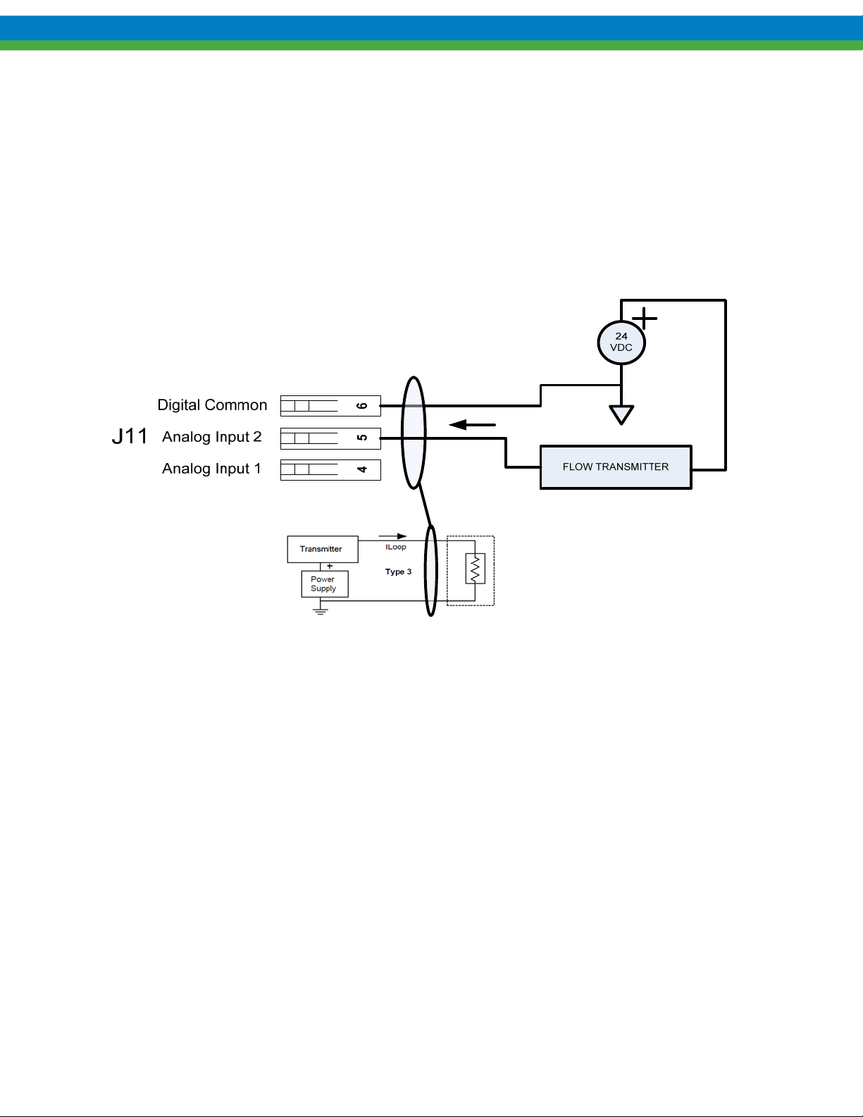
9. Flow Meter Input
The MPC VECTOR accepts flow meter process feedback from an analog (4-20mA) flow metering device. The
manufacturer of the flow meter is not important but the process signal must conform to a set of minimum
specifications in order to work with the MPC VECTOR. See section 13 Specifications
9.1 Flow Meter Installation and Activation
Prior to installation make sure your flow meter conforms to the MPC VECTOR’s flow meter specifications (refer to
Section 13
Specifications. Your flow meter must also be calibrated independently prior to installation.
Figure 9-1– Flow Meter Connection
1. The system information is displayed, the starting display will be:
SETPT XX.XXX
FLOW XX.XXX
2. Press the MENU key
-MENU-
CALIBRATION
3. Press the UP arrow key
-MENU-
SYSTEM SETUP
4. Press the ENTER key
59
Page 66

SYSTEM SETUP
STATUS
5. Press the DOWN key five (5) times
SYSTEM SETUP
FLOW METER
6. Press the ENTER key to enter the Flow Sensor setup menus.
FLOW METER
METER TYPE
7. Press the ENTER key to see the current sensor configuration.
SENSOR TYPE
INACTIVE
8. Press the ENTER key to change the sensor type.
SENSOR TYPE
<INACTIVE>
9. Press the UP arrow key until the analog flow meter option is displayed.
SENSOR TYPE
<ANALOG>
10. Press the ENTER key to accept the new configuration.
SENSOR TYPE
ANALOG
11. Press the MENU key several times to return to the Main screen.
12. Perform either a WET or DRY Pump Flow Calibration on your MPC VECTOR (see Section 8.1.2
Pump Flow Scaling and Calibration ).
13. Your MPC VECTOR is now ready for use with your flow meter.
Closed Loop
60
Page 67

10. AC Input Voltage Setting
Warning: Do not set this parameter if your installation line voltage is 230 or 480 VAC.
If your AC line input voltage is 200-208 VAC or 318-400 VAC then you must set parameter number 01 to a
value of 2, indicating low line voltage to the AC drive. The AC drive needs this voltage calibration in order
to monitor bus voltages and motor current, ensuring protection of your pump motor.
1. Starting from the main operational screen
SETPT XX.XXX
FLOW XX.XXX
2. Press the MENU key
-MENUCALIBRATION
3. Press the UP arrow key
-MENUSYSTEM SETUP
4. Press the ENTER key
SYSTEM SETUP
STATUS
5. Press the DOWN key
SYSTEM SETUP
TCF PARAMETERS
6. Press the ENTER key
PARAM 01
VALUE 1
7. Press the ENTER key
PARAM 01
VALUE <1>
8. Press the UP arrow key
PARAM 01
VALUE <2>
9. Press the ENTER key
PARAM 01
VALUE 2
10. Press the MENU key
TCF PARAMETERS
ACTIVE
11. Approximately 2 seconds
SYSTEM SETUP
TCF PARAMETERS
61
Page 68

12. Press the MENU key several times to return to main operational screen
13.
Your MPC VECTOR is now ready for use with lower voltage ratings of 200-208 or 318-400 VAC.
11. Motor Parameter Setup and Tuning
The MPC VECTOR controller must know several motor characteristics before the motor can be calibrated. This
calibration allows the controller to maintain precise control over the operation of the motor.
Note that the ranges listed in the table below reflect absolute min/max accepted by the drive and may not match a
specific application. These do not have to be set in any particular order but will be presented sequentially by the User
Interface. The parameters will need to be entered in each field if the MPC VECTOR controller was shipped without a
motor, or if the motor is changed to a different model than was originally supplied.
S
ETTING THESE PARAMETERS IMPROPERLY AND RUNNING THE AUTO-CALIBRATION ROUTINE CAN RESULT
IN DRIVE ERRORS
Reference motor parameter table, next page
.
62
Page 69
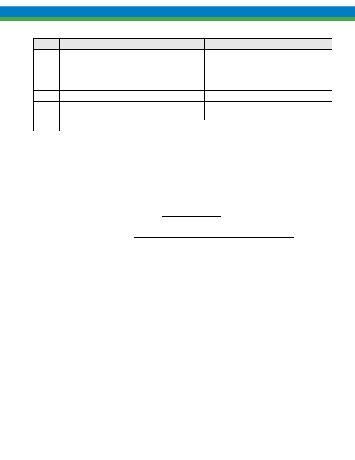
Param. Name Description Range Typical Note
85 Motor Rated Speed Nameplate RPM Rating 300 – 65,000 RPM 1800 RPM
86 Motor Rated Amps Nameplate FLA Rating 0.0 – 480 Amps Various 1
87 Motor Rated Volts Nameplate Voltage Rating 0 – 600 Volts 230/480
VAC
88 Motor Base Frequency Nameplate Frequency 25 – 500 Hz 50 or 60 Hz
91 Motor Power
Factor(PF)
81 Invoking this parameter begins the auto-calibration routine
NOTES:
1. FLA = Full Load Amps
2. The Power Factor, also known as Cosine Phi will sometimes be on the nameplate as “PF”. If the Power
Factor is given as a percentage (%), always use the decimal equivalent (for example a power factor of 84%
would be entered as 0.84) If the Power Factor is not provided by the motor manufacturer, one of the
following formulas may be used.
Nameplate Power Factor 0.4 – 0.99 Approx 0.8 2
Figure 11-1 Motor Parameters
1
rPowerFacto
)2(
rPowerFacto
sincos)1(
CurrentgMagnetizin
CurrentMotor
746
HPMotor
CurrentMotorVoltageMotorEfficiencyMotor
732.1
After all of the Parameters have been entered, the drive needs to perform an auto-calibration routine. This calibration
routine will take several seconds to complete. The user may use the Menu Key to back up and/or out of the
calibration any time prior to the auto calibration. The motor, and therefore the pump, will not run during this auto-
calibration procedure.
63
Page 70

11.1 Motor Parameter Setup and Calibration
1. Navigate to the CALIBRATION menu and press ENTER, and scroll (UP/DOWN) to the MOTOR
PARAM option. The starting display will be:
CALIBRATION
MOTOR PARAM
2. Press the ENTER key
MOTOR RATED RPM
<1750>
3. Use UP and DOWN arrows to adjust value as required, then press the ENTER key
MOTOR CURRENT
<1.2>
4. Use UP and DOWN arrows to adjust value as required, then press the ENTER key
MOTOR VOLTAGE
<230>
5. Use UP and DOWN arrows to adjust value as required, then press the ENTER key
MOTOR FREQUENCY
<60>
6. Use UP and DOWN arrows to adjust value as required, then press the ENTER key
MOTOR PWR FACTOR
<0.80>
7. Use UP and DOWN arrows to adjust value as required, then press the ENTER key
ENTER TO START
8. Press the ENTER key (Note: calibration may take up to a minute)
CALIBRATING
9. The last screen will show
MOTOR PARAM
CALIBRATED
10. Upon completion of the routine, remove power from the MPC VECTOR controller for one minute, and then
re-apply power to complete the process.
64
Page 71

12. Alarm and Error Messages
If a fatal error has occurred while in Operational Mode, the error will flash on the screen and the Red LED will also
flash. The menus can still be accessed by pressing the menu key. This allows the user to try and fix the source of the
error if possible.
12.1 Error Log
As each error occurs an entry is saved in an Error Log. You may view the four most recent errors as well as the
current status through the System Setup Menus.
12.1.1 Viewing the Error Log
1. The starting display will be:
SETPT XX.XXX
FLOW XX.XXX
2. Press the MENU key
-MENU-
CALIBRATION
3. Press the UP arrow key
-MENU-
SYSTEM SETUP
4. Press the ENTER key
SYSTEM SETUP
STATUS
5. Press the ENTER key again to view the current status
--NO—
--ERROR—
6. Press the DOWN key to view the most recent system error
ALARM
LEAK DETECT
7. Continue pressing the DOWN key to scroll through the 4 most recent errors.
8. Press the MENU key at any time, while viewing either current status or Log entries, to exit the Error Log.
Once you see ‘NO ERROR’ in the Error Log (the screens AFTER current status) there will be no errors in any
of the subsequent positions. If the pump turns off for any reason check the Error Log to see any messages that
were reported. Some errors may clear themselves from the screen, but the entry will still be in the Error Log.
12.1.2 Clearing Error Log Entries
Any of the entries in the Error Log may be cleared while viewing by pressing the ENTER key. If the problem is
recurring or still present it may not be clearable.
65
Page 72
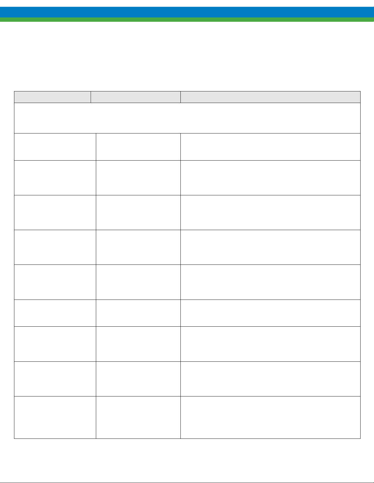
12.2 Alarm and Error Message System Behavior
The following table gives an example of these messages and when you can expect them to be displayed.
Message Displayed When: Error Clearing/Pump Response
FATAL ERRORS: The pump and controller will not run while one of these error conditions exists. The Red LED will
blink and the error message will flash on the screen. Users can access the menu system by pressing the MENU key. The red
LED and the message will cease when the error condition has been corrected.
Analog Input #1
Out of Range
FLOW METER
SIG.LOW/MISSING
--ALARM-LOW LEVEL
--ALARM--
LEAK DETECTED
PUMP FLOW
NOT DETECTED
--ALARM--
AC DRIVE FAULT
The analog input is less than
2.4 mA or greater than 24
mA
The flow meter feedback
signal (Closed Loop
Operation) has fallen below
2.5 ma or is missing.
The tank level monitoring
digital input has triggered
The leak detection
monitoring digital input has
triggered.
The flow detection
monitoring digital input has
triggered. (Only available in
open loop mode)
Internal fault
Self-Clearing- Pump motor will stop and remain stopped until
the signal is between 2.4 and 24mA. The pump will resume
speed or flow when the signal is returned.
Self-Clearing – Pump motor will stop, closed loop operation
will cease. Once signal is returned closed loop flow operation
will continue.
Self-Clearing – Pump motor will stop when a tank level input is
activated. When the tank level input is deactivated, the pump
motor will start automatically in remote mode. Manual mode
requires a pump restart (on/off pressed)
Self Clearing/Self-Latching – Pump motor will stop when the
leak detection input is activated. When the leak input is
deactivated, the pump motor will not start and will require a
manual restart.
Not Self-Clearing (Latched) – Pump motor will stop. Pump
may not be restarted until cleared. Pump must return to manual
mode in order to be restarted. (Remote restarts on flow not
detected not allowed)
Not Self-Clearing (Latched) - Pump Motor will stop. Record
AC drive error code on AC drive LED screen and Consult
Factory. Cycle power to attempt to clear fault.
AC DRIVE FAULT
COMMUNICATION
COMMUNICATION
--ERROR--
--ALARM--
PULSAGUARD
Communication error exists
between the MPC VECTOR
controller and the AC
DRIVE
Communication error exists
between the MPC VECTOR
controller and the
keypad/display module
Flow has fallen below or not
gone above user defined low
flow threshold for 20
seconds.
Self-Clearing – Pump motor will stop after 10 seconds of loss of
communications between the controller and AC drive. When
communications are restored the pump will restart.
Not Self-Clearing (Latched) – In Manual Mode the pump will
stop after a 20 second interval if communication is not restored.
In Remote Mode the pump will continue to run when
communications is lost between the keypad and controller.
Not-Self Clearing – Pump motor will stop, closed loop
operation will cease. In manual (local) mode the pump must be
restarted with the on/off key. In remote mode the pump will
keep attempting to restart after each PulsaGuard alarm is
recognized.
66
Page 73

Continues next page…
67
Page 74
NON-FATAL ERRORS: The pump and controller can still be run while these conditions exist.
The Red LED will flash and the error will flash on the screen. The Red LED and error message
will cease once the error condition has been corrected.
The flow set point has not been attained for duration of 60
PUMP FLOW
OUT OF RANGE
Self Clearing - Pump Motor will continue to run, showing a
pump flow out of range error message. Once actual flow
seconds. (Closed Loop Operation Only)
meets the flow set point the warning will clear.
CONSULT factory
Error = ####
USER NOTIFICATIONS: These are errors in setup or calibration. They will display on the
screen for several seconds. They can be corrected by properly completing the procedure
involved.
Cannot access
With motor on
Current delta
Out of range
No remote
Control
For unlisted or numbered error codes, consult the factory for assistance.
Unidentified error, record error number and consult factory
User is trying to change a setting that cannot be changed
while the pump is running. Press motor on/off key to turn
motor off.
Not enough difference between high and low signals during
an analog input signal calibration (min 3 mA)
User is trying to activate the AUTO mode, but the analog
input is not active or remote on/off is not configured for the
controller.
68
Page 75
13. Specifications
Control Inputs
Analog In #1
Analog Flow Meter
Input
J11 pins 4(+) and 6(-) 4-20mA control signal
J11 pins 5(+) and 6(-) 4-20mA flow meter feedback signal
Wiring Specification / Description
Max current 30mA; Input resistance 200 Ohm
Internally protected with self resetting fuse
Minimum signal accepted = 2.4 mA
Maximum signal accepted = 24 mA
Max current 30mA; Input resistance 200 Ohm
Internally protected with self resetting fuse
Minimum signal accepted = 2.4 mA
Maximum signal accepted = 24 mA
Digital In #1
Digital In #2
*Do not apply power, maximum 2K Ohm resistance to register as “active”
Digital input functions:
J11 pins 1-3 User to provide dry-contact input *
J11 pins 2-3 User to provide dry-contact input *
1. Remote on/off control of pump
2. Level input from supply tank
3. Leak Detection with external device
4. Flow detection with external device
Control Outputs
Analog Out #1
Digital Out #1
Digital Out #2
Digital Out #3
* All digital outputs maximum 24 VDC, maximum 500 mA
NOTE: requires external power source
Digital output functions:
Input Voltage: Nominal: 230 (208/240 acceptable range) VAC
Nominal: 480 (400/480 acceptable range) VAC
Wiring Specification / Description
J23 pins 5-6 4-20mA output for pump flow indication
Max voltage out 12 Volts; Max current out 30mA;
Max load resistance 300 Ohm
Internally protected with resettable fuse
J23 pins 1-4 Transistor-based output, various functions *
J23 pins 2-4 Transistor-based output, various functions *
J23 pins 3-4 Transistor-based output, various functions *
1. Triggering an external relay due to a fault condition
2. Auto/Manual status
3. On/Off status
4. Leak Detected
5. Tank level status indication
69
Page 76

Note: factor y configured only for correct input voltage range (specified at time of purchase)
Single Phase or Three-Phase (Single-Phase not available for 5 hp)
50 or 60 Hz.
Tolerance: Input voltage +10%/-15% maximum
Input frequency range 48 Hz to 62 Hz
Motor Req: Commercially available motor supplied by the manufacturer of the pump controller
See Section 14 for motor selection requirements
Motor Distance: Maximum motor to controller distance is 100 feet (30.5 meters)
For distances greater than 25 feet (7.6 meters) see motor information, next page
Consult factory for distances greater than 100 feet (30.5 meters)
Keypad: Mo unted to MPC VECTOR main enclosure, can be made remote from the enclosure, maximum of 1000 feet
Display: Backlit 2 lin e extended temperature 16 character LCD
Enclosure: NEMA 4X and IP56 ratings and open chassis panel mount option available
Altitude: 3300 Ft (1000 M) above sea level (derate 5% HP for each additional 3300 feet)
Humidity: 0-90% (non-condensing)
Temperature: 0
40
o
C (32o F) Minimum operating temperature
o
C (104o F) Maximum operating temperature
Earth Leakage
Current: Size Earth Leakage Circuit Breakers (ELCB) to a detection level of 30 mA or greater
70
Page 77
14. Pump Motor Selection
Your MPC VECTOR pump controller can accept input power in the at frequency ranges of both 50 and 60
Hz power. This allows your controller to be run from 50 and 60 Hz line frequency locales. Your motor supply
frequency may be 50 or 60 Hz and is independent of your supply input frequency as the motor’s input supply
frequency is generated by the AC drive. Maximum synchronous motor speed (derived from the frequency of
operation); however, will directly affect your pump flow capacity (maximum flow rate). In general, 60 Hz motors
will have a theoretical synchronous speed of 1800 RPM while 50 Hz motors will be 1500 RPM. The speed
difference theoretically results in a pump capacity reduction of approximately 17%.
14.1 General Specifications
All motors used with the MPC VECTOR controller must meet these minimum specifications:
50 or 60 Hz 3-phase input power AC induction motor
o 208/230 VAC for 208/240 VAC In put Voltages
o 400/460 VAC for 400/480 VAC In put Voltages
1800 rpm (60 Hz) or 1500 rpm (50 Hz) synchronous speed
Service Factor 1.05 or greater
Class F Insulation (minimum)
Refer to your equipment specifications and documentation f or the correct frame size
Motors may or may not need feet and/or a C-face mount depending on equipment
14.2 Motor Type and Turndown Requirements
Motor turndown is defined by the ratio of motor base speed to the slowest speed used in the pump application. Pump application
specifics will determine the motor type and turndown required to drive your pump.
Motor turndown ratings are dependent on the application and intended use of the pump . Users should understand and take into
account the following factors when considering motor selection:
Application required turndown ratio
Motor Cooling
Length of wiring between the MPC VECTOR controller and the pump (motor)
Application Turndown
Shown below are the typical motor types and recommended maximum turndowns. The user must ensure that the positive
displacement pump application can operate over the turndown range (that is max flow to turndown flow) effectively in order to fully
utilize the turndown range of the motor. Shown below are the typical motor types and recommended max imu m turndowns.
Motor Type Typical Turndown
Commercial Duty Motor 2:1
Premium Efficiency Motor (Inverter Ready) * 4:1 – 10:1
Inverter Duty Motor* Up to 15:1
Vector Duty Motor Up to 20:1
*All motors must be inverter ready per NEMA Standard MG1 Part 31, failure to comply may result in premature motor winding
breakdown and motor failure.
71
Page 78
Motor Cooling
Motor cooling will be dependent upon motor selection. Premium efficiency motors will generally provide cooling from a shaft
mounted fan. Typical motor type would be Totally Enclosed Fan Cooled (TEFC). Motors of this type should use a maximum turndown
of 10:1 as low speed operation leads to inefficient fan cooling, resulting in premature bearing and winding failure. Inverter Duty and
Vector Duty motors are designed to be used for lower speed (higher turndown) applications and generally are Totally Enclosed Non
Ventilated (TENV). Cooling is provided via convection and a large heat sinking motor enclosure.
Motor to Controller Cable Distance
Motor to controller distance in all cases should be minimized. AC drive motor control waveforms are formed from a DC bus and
are “chopped” to create an AC control waveform. These waveforms create motor wiring high voltage spikes. These spikes are made
worse with longer cabling (due to impedance mismatch and the corresponding reflected waveform, dv/dt). These reflected waveforms can
easily double the voltage seen by the motor windings.
Cable Length Minimum Required Motor Turndown Rating
MPC VECTOR to motor less than 25
feet (7.6 meters)
MPC VECTOR to motor greater
than 25 feet (7.6 meters)
Use ratings guidelines in chart above
4:1 or 10:1 turndown 20:1 turndown
Must use 10:1 inverter duty
rated motor
Consult factory
NOTE: the maximum pump to controller distance is 100 feet (30.5 meters). If longer distances are required, please contact the
factory. Line and load reactors can be utilized to allow operation over lo nger distances.
72
Page 79
15. Model Identification
Position Sample Specifies Options
1 and 2 EP
3 C
P
4 B
EP – MPC VECTOR
Enclosure Type C – Enclosure meets NEMA 4X specifications
P – Panel Open Chassis, Remote NEMA 4X
Motor HP/Input
Voltage Rating
B - 2 Hp (1.5 kW); Drive Input: 208-230 VAC
C - 3 Hp (2.2 kW); Drive Input: 208-230 VAC
*
A - Fractional to 1.0 Hp (0.75kW); Drive Input: 208-230 VAC
D - 5 Hp (3.7 kW); Drive Input: 208-230 VAC (3-phase only)
E – Fractional to 1HP (0.75kW) – 480 VAC (3 phase only)
F – 2 Hp (1.5 kW); Drive Input: 480 VAC (3 phase only)
G – 3 Hp (2.2 kW); Drive Input: 480 VAC (3 phase only)
H – 5 Hp (3.7 kW); Drive Input: 480 VAC (3-
phase only)
5 X
Language X – English (default)
A - German
B - French
C - Spanish
* Reference specific motor selection requirements in Section 14.1 General Specifications
73
Page 80
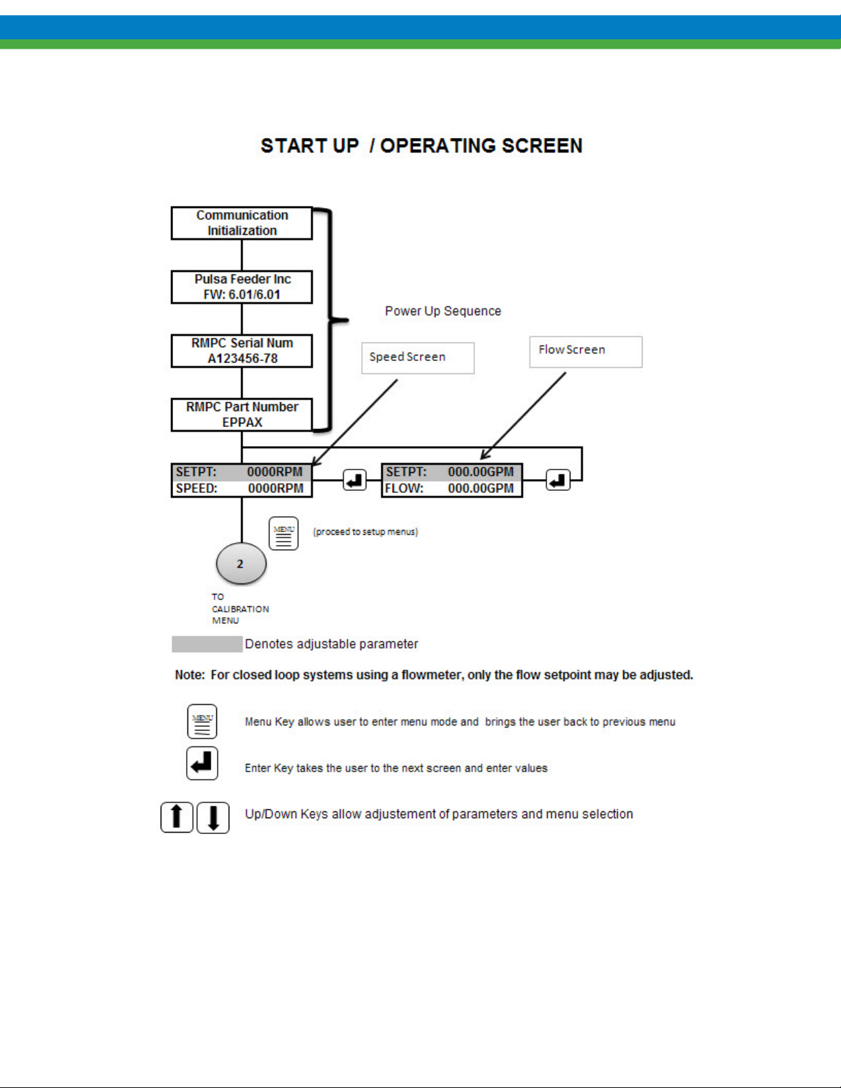
16. Menu Maps
74
Page 81
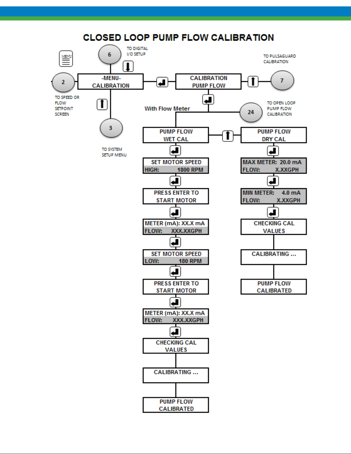
75
Page 82
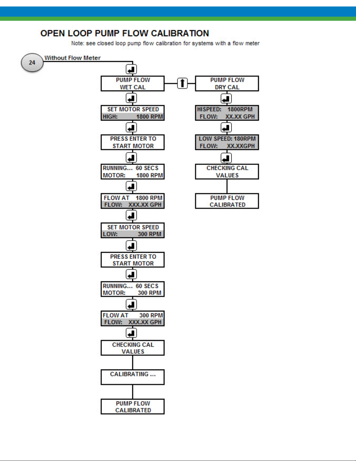
76
Page 83
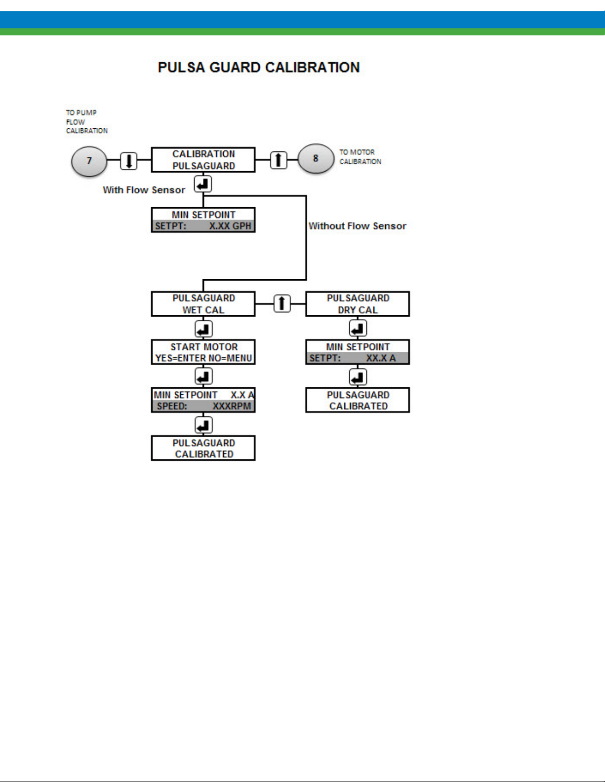
77
Page 84
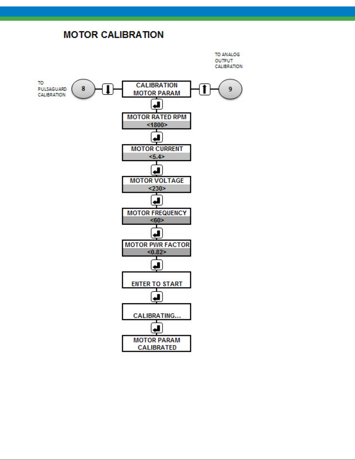
78
Page 85
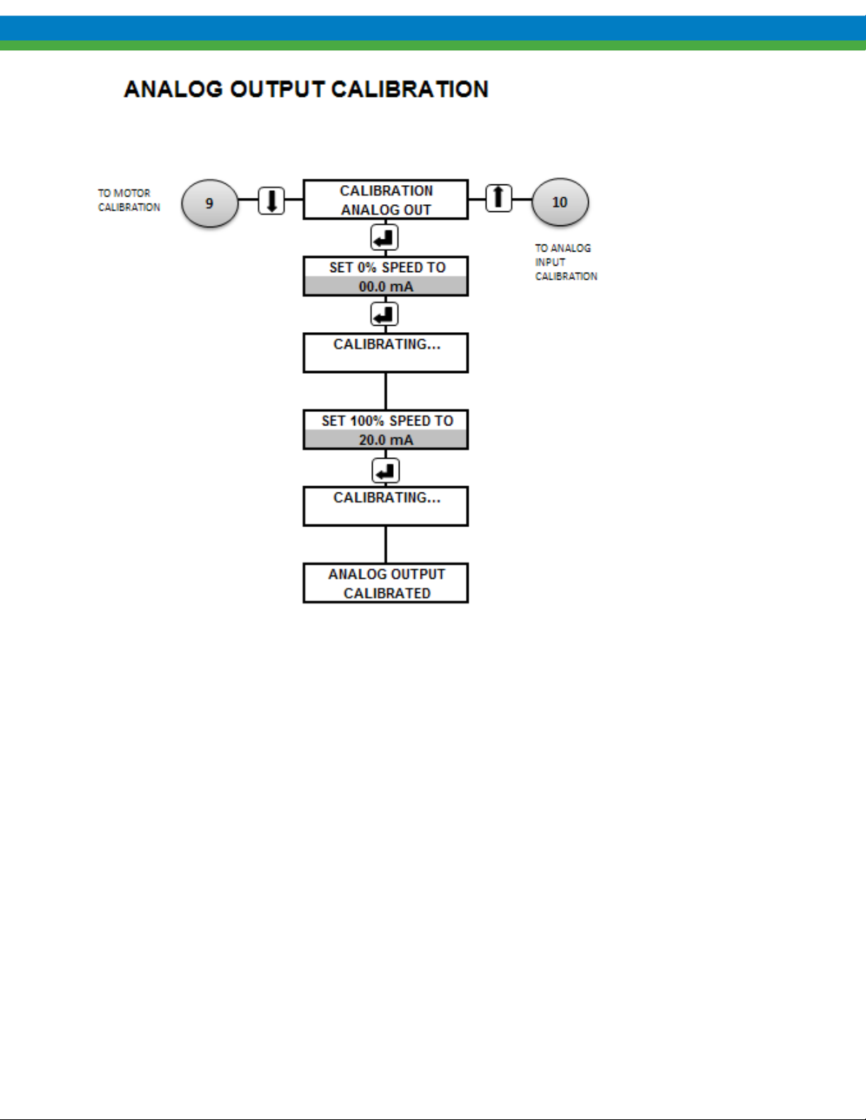
79
Page 86
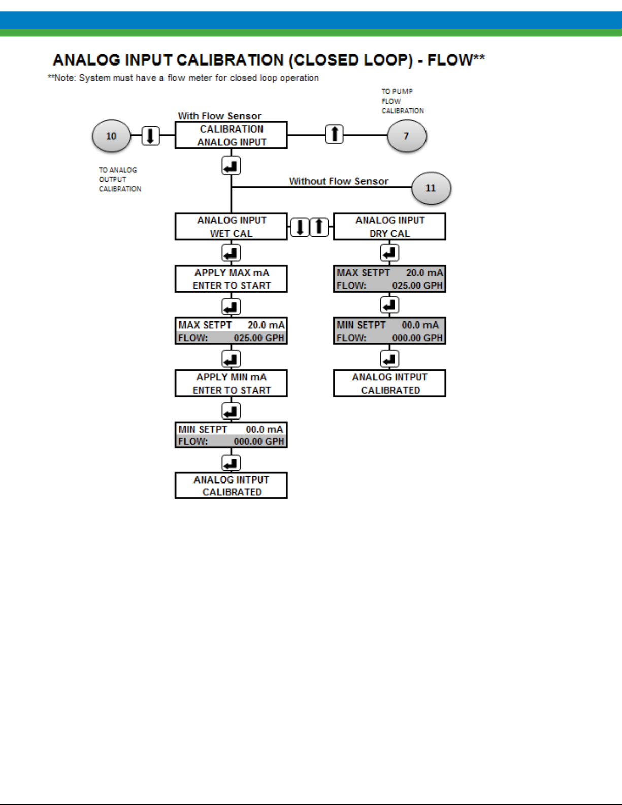
80
Page 87
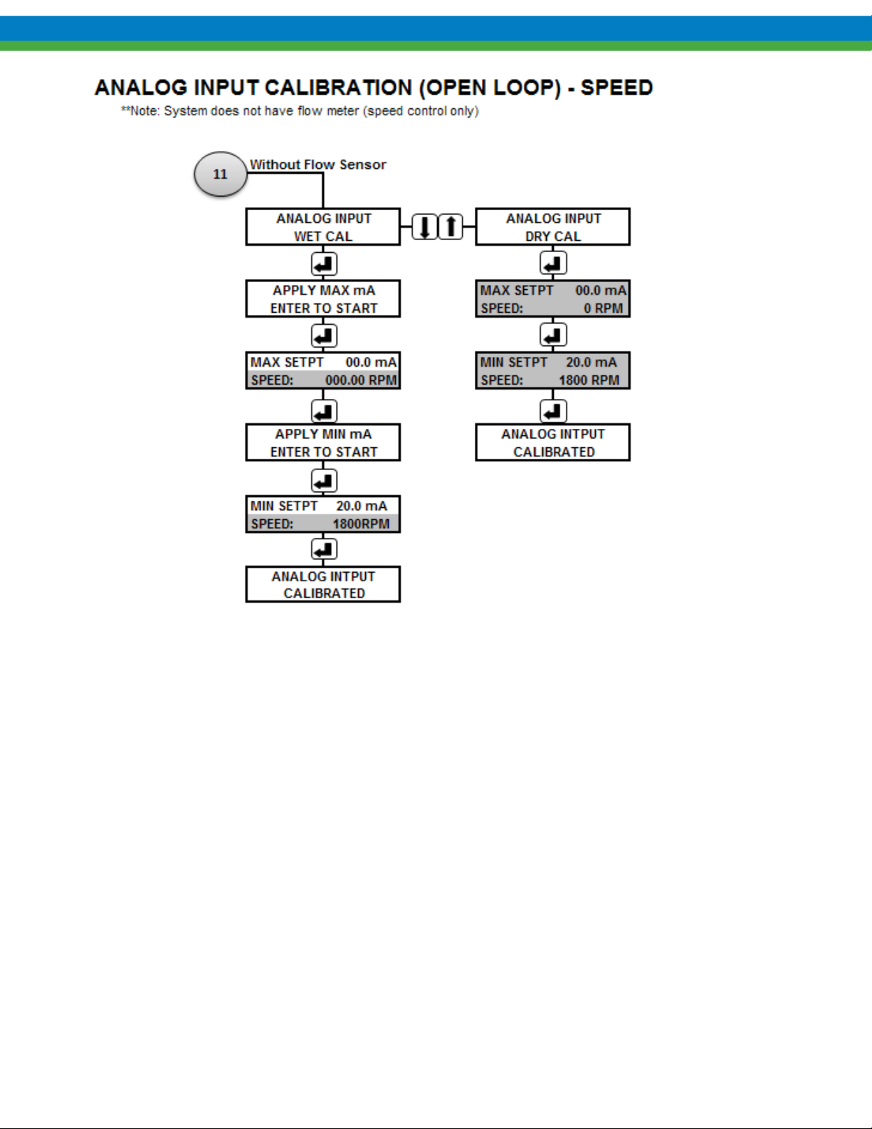
81
Page 88
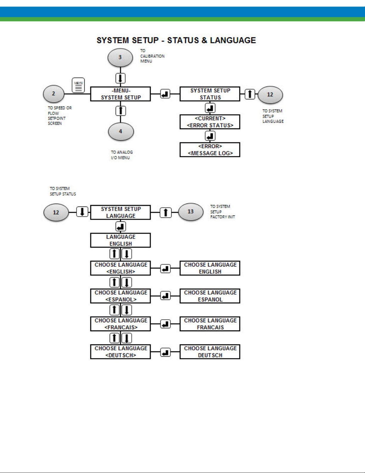
82
Page 89
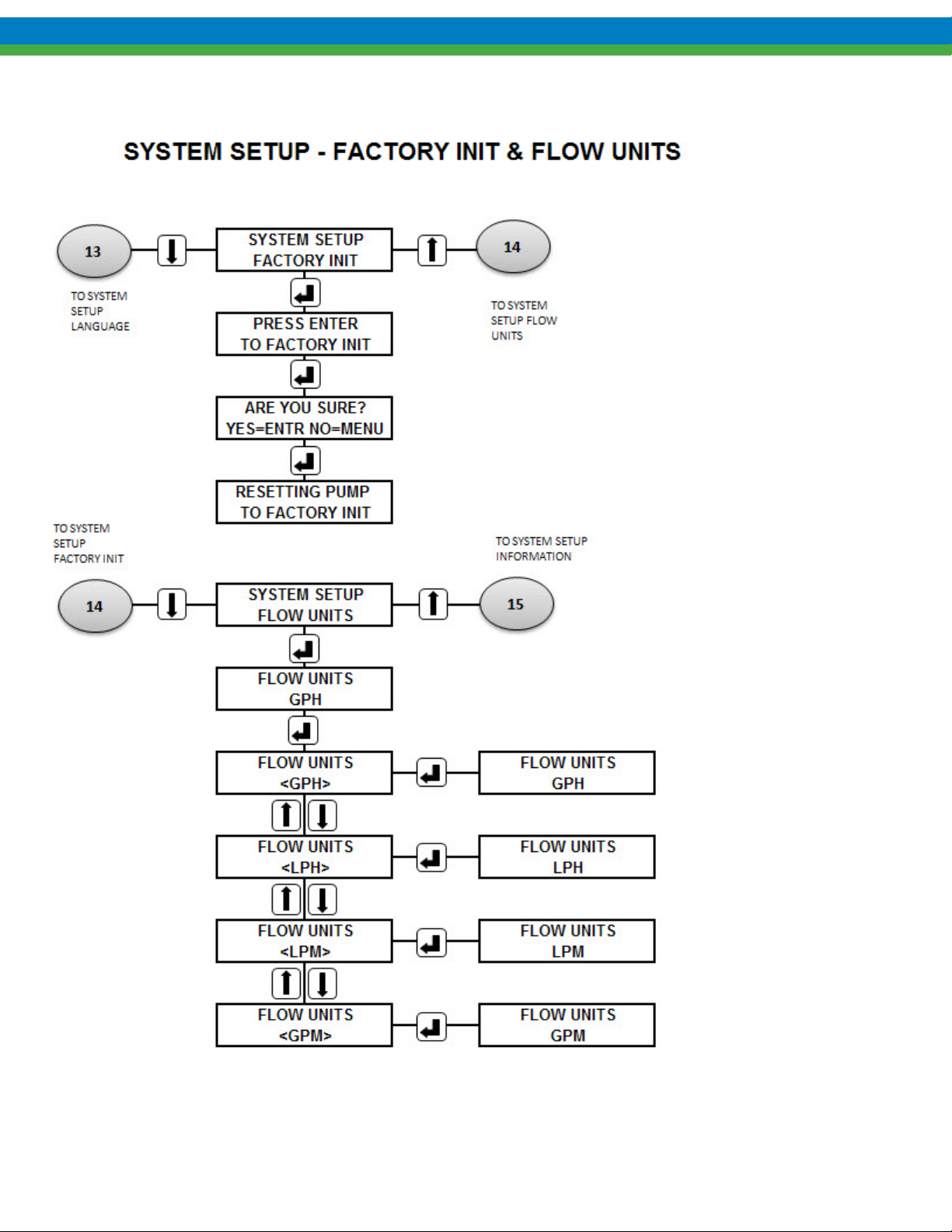
83
Page 90
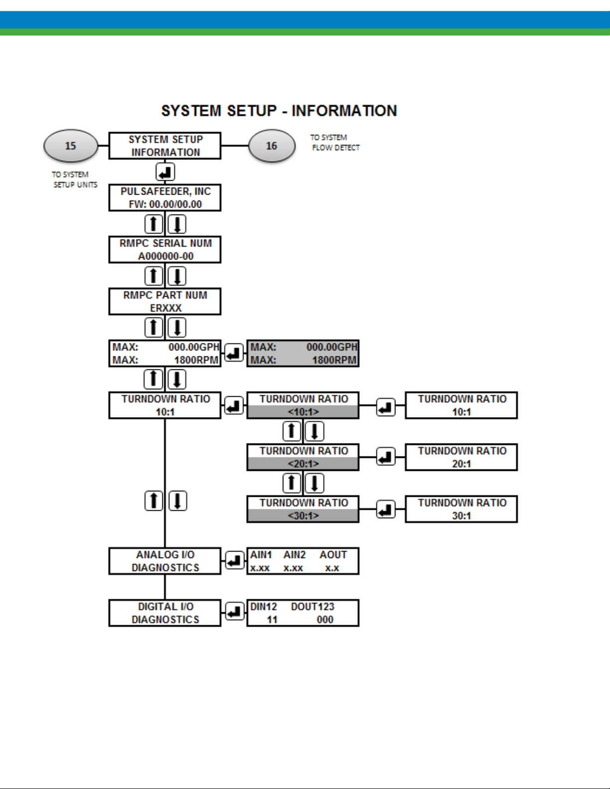
84
Page 91
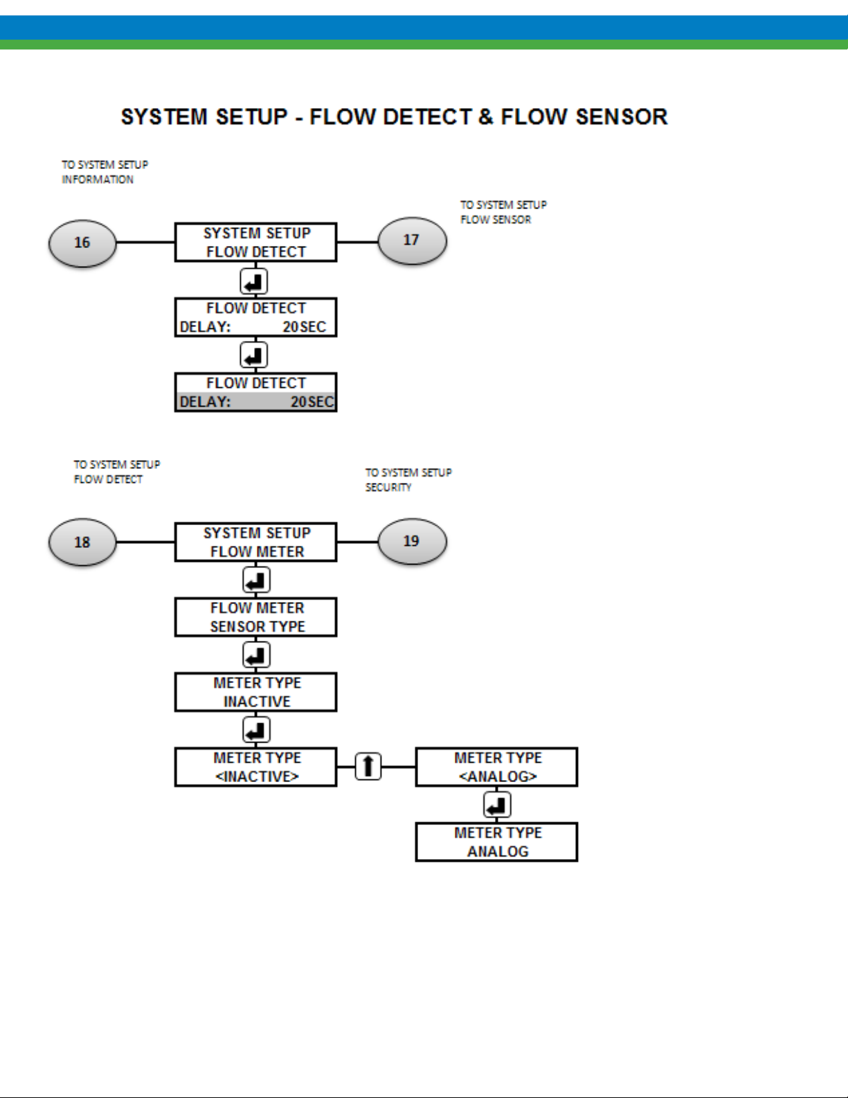
85
Page 92
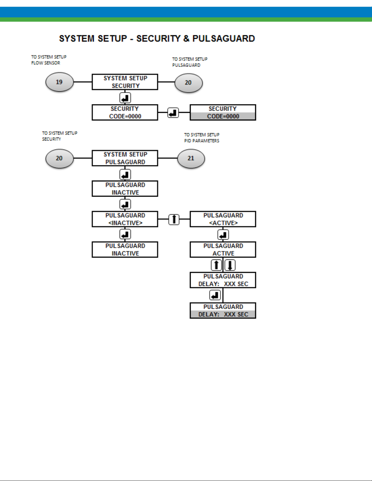
86
Page 93
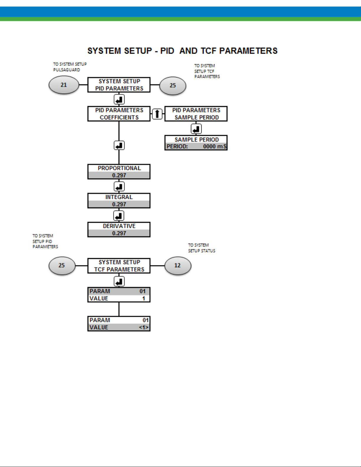
87
Page 94
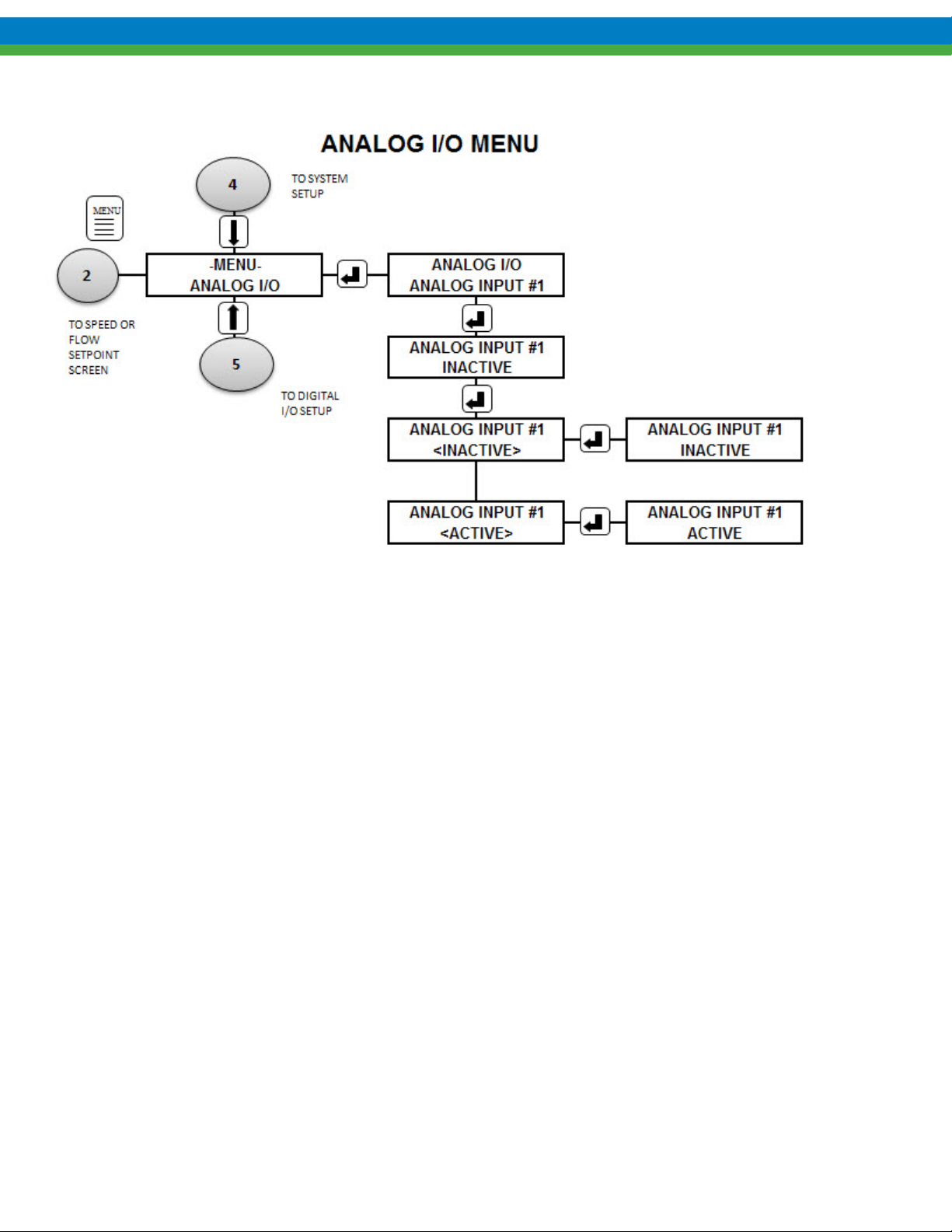
88
Page 95
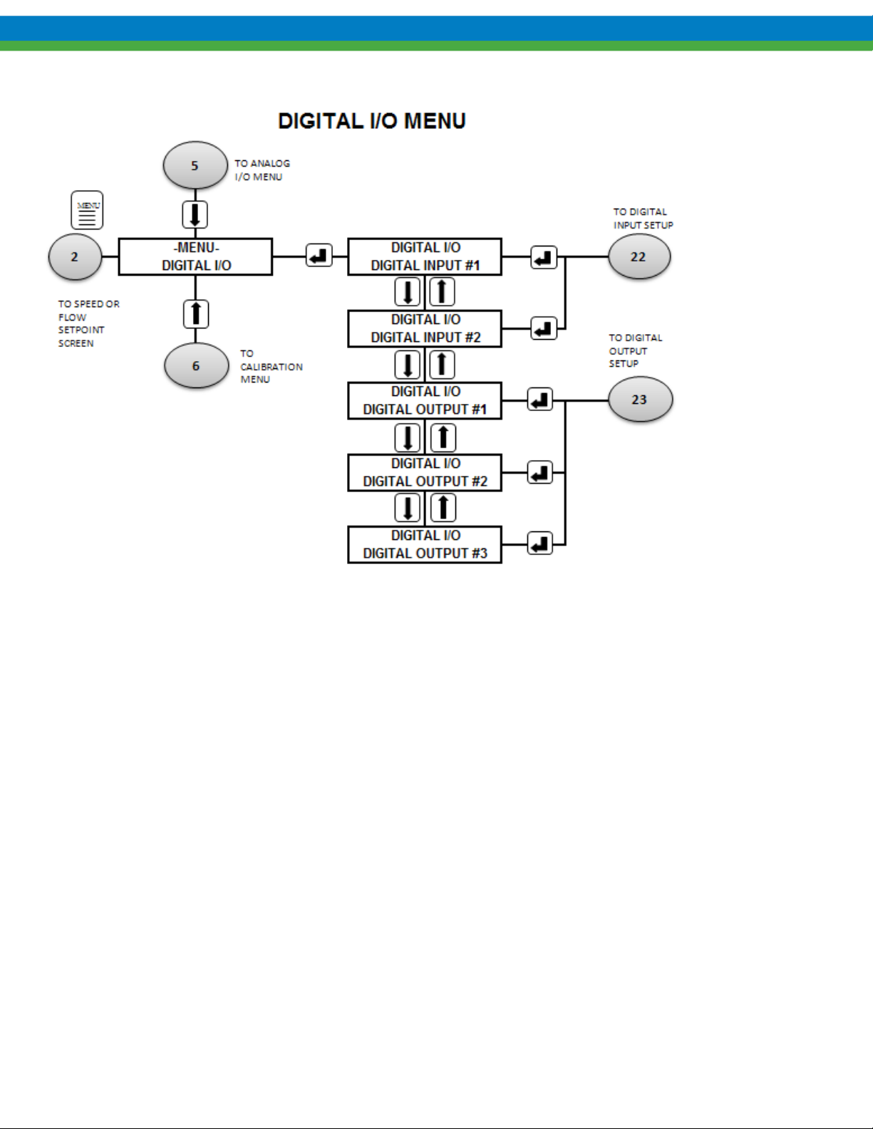
89
Page 96
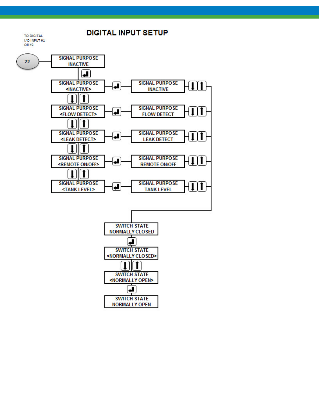
90
Page 97
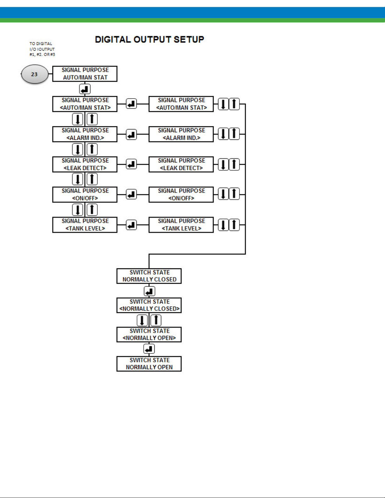
91
Page 98
17. Factory Default Values
Parameter Factory Set Value
Digital Input #1 INACTIVE, normally closed
Digital Input #2 INACTIVE, normally closed
Analog Input #1 INACTIVE
Analog Input #2 INACTIVE
Digital Output #1 ON/OFF indication, normally closed
Digital Output #2 AUTO/MANUAL Indication, normally closed
Digital Output #3 ALARM Indication, normally closed
Security Code Default = 0000
Language ENGLISH
MODE Local (Manual)
UNITS GPM (gallons per minute)
18. Retrieval of Setup Information
Users can access the system SETUP: INFORMATION menu, which will list the following data, this may be
helpful in troubleshooting:
Controller software revisions
Pump serial number
MPC VECTOR model number
Pump maximum flow
Pump maximum speed
Pump Turndown
92
Page 99
19. Troubleshooting Guide
Problem Potential Cause Solution
POWER
No AC drive red LEDs lit
Should see “---“after power up
sequence.
No Green LED blinking on controller
board.
Green LED not blinking on controller
(local) board.
LED backlighting not lit on remote
handheld, but green LED blinking at 1
second interval on local board.)
LED’s not lit, keypad not responding Remote keypad connector not seated
LCD display not readable, no text on
display (too light/too dark)
No Text on LCD display Improper software initialization Remove power for 5 seconds then
Handheld displays
“AC Drive Fault
Communications”
on LCD handheld screen.
Handheld displays
“Communication
--ERROR—“
Handheld displays
“AC Drive Fault
OVERCURRENT”
Improper AC line input wiring or low
line input voltage.
DC power supply not powered. Check Blue and Brown wire for voltage
DC power supply not providing output
power to local control board.
Check L1, L2, L3 for proper voltage
(230/480 VAC) and wiring. Check
circuit breakers.
at power supply
230 VAC systems = ~1.4 * AC line =
1.4 * 230 = 325 VDC
480 VAC systems = 230 VAC
Check voltage with meter on output of
power supply
Black(-)-to-Red(+) = 5vdc
Black(-)-to-Green(+) = 12 vdc
HANDHELD DISPLAY
Remote handheld not receiving power. Open Handheld Front Cover and
measure voltage J5-1/2 to J5-3/4.
Voltage should be ~ 12.0 volts dc. See
Figure 21-1 Handheld Remote Wiring
Open Handheld Front Cover and
properly.
Contrast not adjusted properly. Use ENTER key with UP ARROW and
measure voltage and check J4 for
proper connection. See Figure 21-1
Handheld Remote Wiring
DOWN ARROW keys to adjust darker
and lighter, respectively.
reapply.
SYSTEM ERRORS
Communications link between the AC
drive and local board has timed out
Communications link between the local
control board and the handheld remote
has timed out.
Motor is drawing excessive current and
the AC drive is limiting its output.
Ensure 3 wire connection from local
control board to AC drive. J28 on local
board to drive control terminal strip
pins 2-ground (green), TXA (red), and
TXB (black).
Ensure connections between local board
and remote handheld are made. See
Figure 21-1 Handheld Remote Wiring
for connection details. Be sure to check
black/white and white wires.
Ensure proper motor sizing and drive
sizing for application.
93
Page 100
DRIVE ERRORS AND FAULTS
Drive module display reads “CL” Drive has gone into a current limit
mode to protect the pump motor.
Drive module display reads “nld” An attempt was made to start the
controller prior to calibrating the pump
motor.
Drive module display reads “HF” or
“LF”
The AC drive DC bus is to high (HF) or
the DC bus is too low (LF)
Drive module display reads “PF” Current Overload has occurred and
drive shuts down.
Drive module display reads “F1-F9” Drive has internal fault. Consult factory
Check for pump binding or drive/ motor
combination being undersized.
Perform a motor calibration as outlined
in Section 6.4 Motor Parameter Setup
Check incoming line voltages for proper
input tolerances. See Section 13
Specifications for input tolerances.
Check pump for binding or mechanical
failure.
Problem Potential Cause Solution
DISPLAY
No Display No power supplied. Check power source. plug & circuit breaker
Back-lighting Supply power wired incorrectly. Check wiring.
Supply power outside of specification. Check voltage/frequency against specification.
No Text on
Display
Contrast out of adjustment. Adjust as per section 8.4
Software did not initiate properly. Remove and re-apply AC power
POWER
No power No power supplied. Check power source. Plug & Circuit Breaker
Indicators Supply power wired incorrectly. Check wiri ng .
Supply power outside of specification. Check voltage/frequency against specification.
94
 Loading...