

Page 1

1
INSTALLATION & SETUP GUIDE
FOR SINGLE POLE & 3-WAY CONFIGURATIONS
iDEVICES SMART HOME SOLUTIONS
Page 2

2
REQUIRES
• Wi-Fi® 2.4 GHz 802.11 b/g/n
Compatible Network
• Router Security Settings
Supported: WPA, WPA2, Or None
• Free iDevices® Connected App
• 120VAC “Line” (usually black,
blue or red) And “Neutral”
(usually white) Wires In Each
Gang Box
• Controlling this HomeKit-enabled
accessory requires an iPhone,
iPad, or iPod touch with iOS 8.1
or later.
• Android™ 4.3+ Device With
Bluetooth® Technology
TOOLS NEEDED
• Philips Screwdriver
• Flathead Screwdriver
• Pliers
• Wire Cutter/Stripper
• Voltage Detector
RATINGS
Input: 120-277VAC, 50/60Hz
Output: 120-277VAC, 50/60Hz
Resistive: 1800W @ 120-277VAC, 15A/6.5A
Tungsten: 960W @ 120VAC, 8A
Tungsten: 1800W @ 277VAC, 6.5A
Motor: 1HP @ 120 & 277VAC
Ballast: 10A @ 277VAC
Page 3

3
• Not intended for critical medical or life support equipment.
• Use caution when using the iDevices® Wall Switch to control any appliances which produce heat or
mechanical motion, or could create a hazardous condition when operated while unattended.
• The iDevices® Wall Switch is not user-serviceable. Do not attempt to open the enclosure for any reason.
• The iDevices® Wall Switch must be installed in a manner that conforms to all applicable national,
state, and local building codes.
• The iDevices® Wall Switch is intended for dry, indoor use only.
• Ambient operating conditions: 32º F to 104º F (0º C to 40º C), 0-90% humidity, non-condensing.
• Use with branch circuit breaker 20A or less.
• Notice - Use only copper or copper-clad wire with this device.
RISK OF ELECTRIC SHOCK, SEVERE BURNS, AND FIRE: Your safety is important to us.
Electricity is dangerous and can cause personal injury and property damage if handled improperly.
A working knowledge of electrical installation is required to install this product. If you are not
comfortable working with electricity do not attempt to install the iDevices® Wall Switch and seek
professional assistance from a qualied electrician.
!
Page 4

4
BEFORE YOU START
• Read through this Installation Guide in its entirety before starting
installation of your iDevices® Wall Switch or removal of your old
switches. Incorrect installation can be dangerous and can damage
your iDevices® Wall Switch or your home. The iDevices®
Wall Switch is intended to be installed by a qualied electrician.
• Visit our YouTube channel for tips on installation and setup:
www.YouTube.com/User/iDevicesInc
• Turn OFF the power to the circuit you are working on at your
home’s breaker or fuse panel.
Page 5

5
• Wherever possible, install the iDevices® Wall Switch in a non-
metallic gang box and use a non-metallic faceplate, as metal gang
boxes and faceplates can decrease the Wi-Fi® signal strength.
• Check that your mobile device is compatible with the iDevices®
Wall Switch at iDevicesinc.com/Compatibility
• It is YOUR responsibility to be sure that products are installed in
accordance with applicable building codes. Check with your local
building ofce if you have questions.
• Download the free iDevices® Connected app.
• For 4-way congurations, visit:
iDevicesinc.com/Support/WallSwitch/Setup
Page 6

6
GETTING TO KNOW THE
iDEVICES® WALL SWITCH
Turn Light On. Used also for 3-way, 4-way pairing.
Turn Light Off. Used also for connecting to the Wi-Fi® network.
Status LED/Night Light. Provides setup status and used as a night light
during operation. Refer to LED color codes on page 42.
Pull Out Tab. Refer to this when prompted to enter your HomeKit™
setup code during the setup on a iOS device. Also used to document the
Wall Switch as the Primary or Secondary in a 3-way or 4-way conguration.
Device Reboot. Pressing this cycles power to the device.
1
4
2
5
3
Page 7

7
Pairing Setup Button. Used
to wirelessly pair multiple Wall
Switches for 3-way and 4-way
congurations and for connecting
to the Wi-Fi® network.
DEVICE RESET: Press and hold for
10 seconds until LED blinks red.
1
6
4
2
56
3
Page 8

8
INSTALLATION - SINGLE POLE
STEP 1
Turn OFF the power at the circuit breaker.
STEP 2
Remove the existing faceplate and switch from the gang box. Take a
photo of the existing wiring for future reference.
STEP 3
Conrm the gang box contains a neutral wire (typically white). If
there are no neutral wires present, you may need to run additional
wires, please consult a qualied electrician.
NOTE: Your home’s wiring may differ; please consult a qualied electrician.
Page 9

9
GROUND
(Usually Bare Copper or Green)
LOAD
(Usually Black)
LINE
(Usually Black, Red or Blue)
NEUTRAL
(Usually White)
GROUND
(Usually Bare Copper
or Green)
Page 10

10
STEP 4
Remove both wires from the terminals of the existing switch and
cap with the provided wire nuts. Note: If you have more than two
wires connected to your switch (not including the bare copper or
green-coated ground wire), please see the 3-way, 4-way installation
instructions. It is not necessary to remove the ground wire.
NOTE: Your home’s wiring may differ; please consult a qualied electrician.
Page 11

11
GROUND
(Usually Bare Copper or Green)
LOAD
(Usually Black)
LINE
(Usually Black,
Red or Blue)
NEUTRAL
(Usually White)
GROUND
(Usually Bare Copper
or Green)
Page 12

12
STEP 5
Turn the power back ON at the breaker. Using your voltage detector,
identify which of the two wires you removed is energized. This is the
“line” wire. The wire that is not energized is the “load” wire.
Note these two wires for future reference.
NOTE: Your home’s wiring may differ; please consult a qualied electrician.
Page 13

13
GROUND
(Usually Bare Copper or Green)
LINE
(Usually Black,
Red or Blue)
NEUTRAL
(Usually White)
LOAD
(Usually Black)
GROUND
(Usually Bare Copper
or Green)
Page 14

14
STEP 6
Turn the power back OFF at the breaker and install the iDevices®
Wall Switch according to the diagram. Ensure all wire nuts are
securely fastened.
NOTE: Your home’s wiring may differ; please consult a qualied electrician.
Page 15

15
NEUTRAL
(White)
NEUTRAL
(Usually White)
LOAD
(Usually Black)
LOAD
(Red)
GROUND
(Bare Copper)
GROUND
(Usually Bare Copper
or Green)
LINE
(Usually Black, Red or Blue)
LINE
(Black)
Page 16

16
STEP 7
Install the Wall Switch into the gang box and install the faceplate.
STEP 8
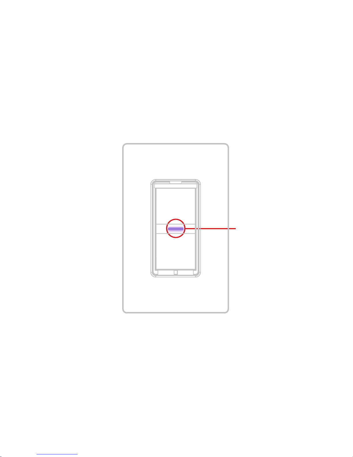
Turn the power back ON at the circuit breaker and conrm that the
LED on the Wall Switch lights up purple.
Page 17
17
LED will light
up purple
Page 18

18
WIRELESS COMMUNICATION SETUP
STEP 1
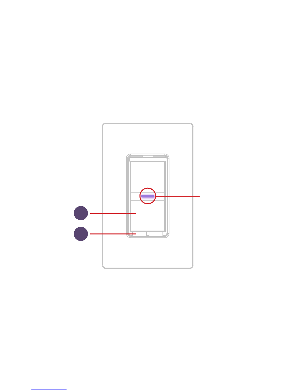
Ensure power/breaker is turned back ON and the LED on the Wall
Switch is solid purple.
STEP 2
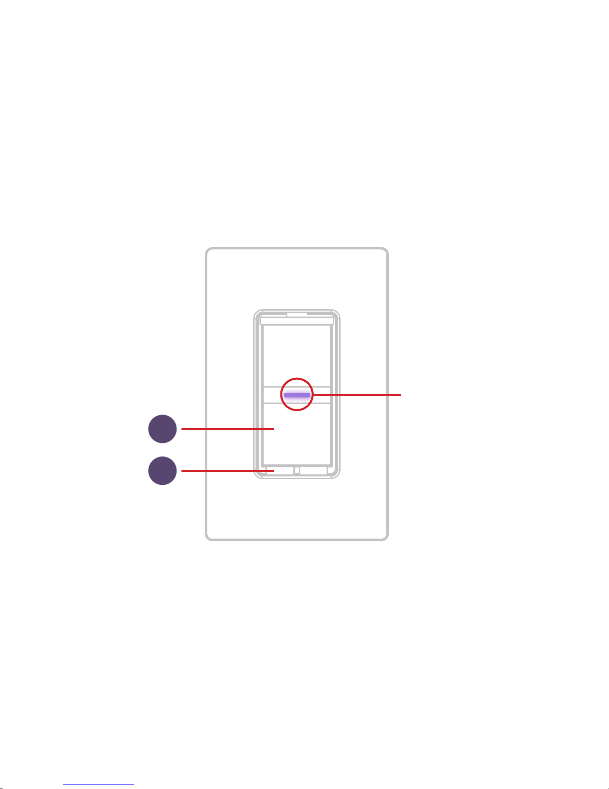
Press and hold “6” for 5 seconds and release when the LED rapidly
ashes blue. Next tap “2” to begin the Wi-Fi® connection process.
Page 19
19
Ensure LED
is purple
2
6
Page 20
20
STEP 3
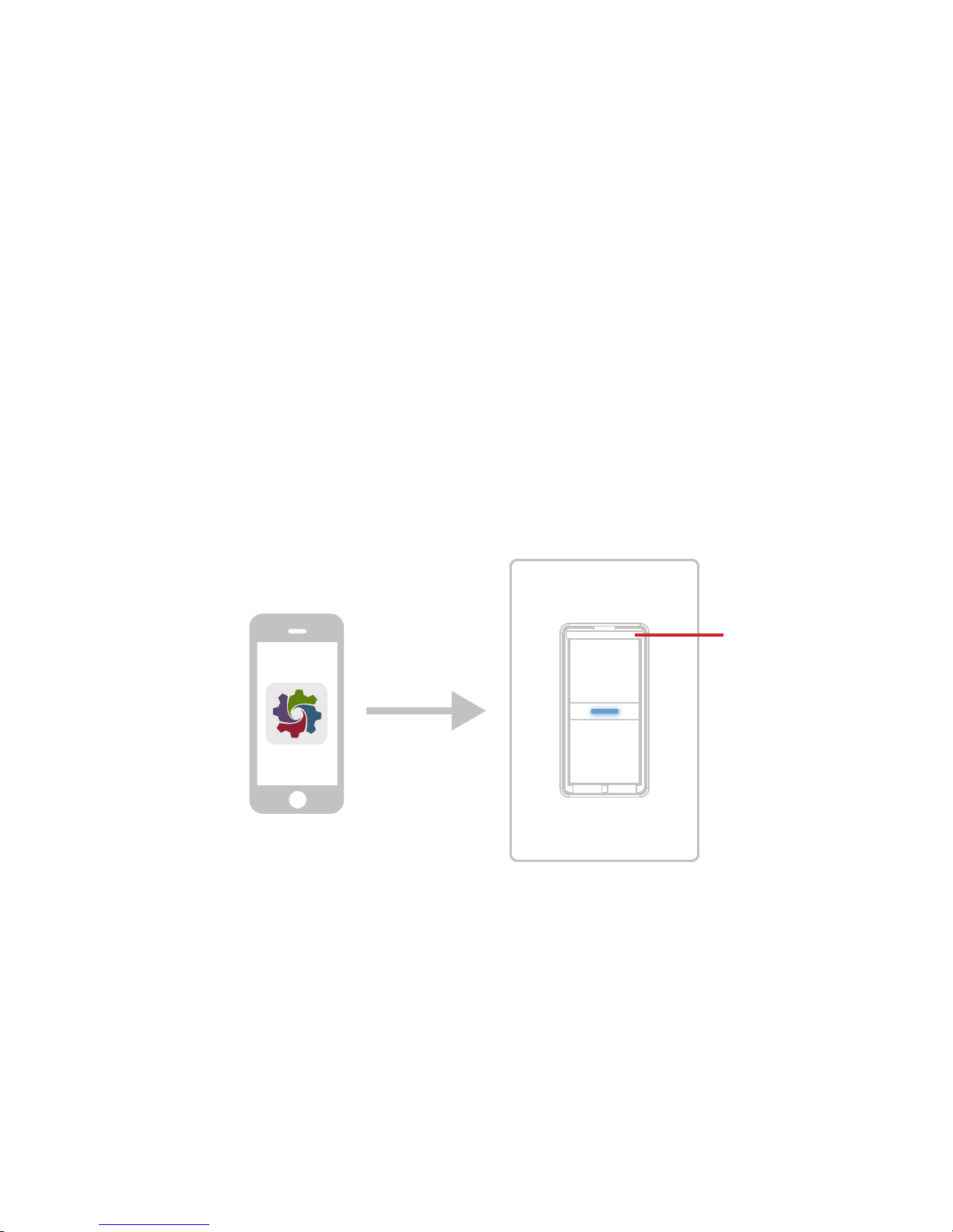
Launch the iDevices® Connected app and you will be guided
through the process of connecting your Wall Switch. For iOS
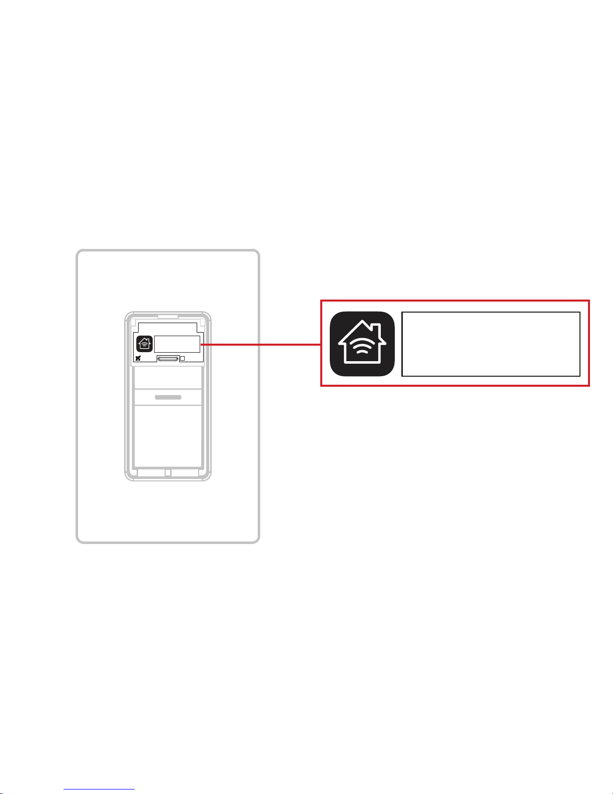
devices, you will need the HomeKit™ setup code on the pull out tab
on your Wall Switch.
Icon
Pull out tab
Page 21
21
Wall Switch - Model: IDEV0008
Primary Secondary
XXX-XX-XXXX
HomeKit™ setup code is located on the
pull out tab of the iDevices® Wall Switch
XXX-XX-XXX
Page 22

22
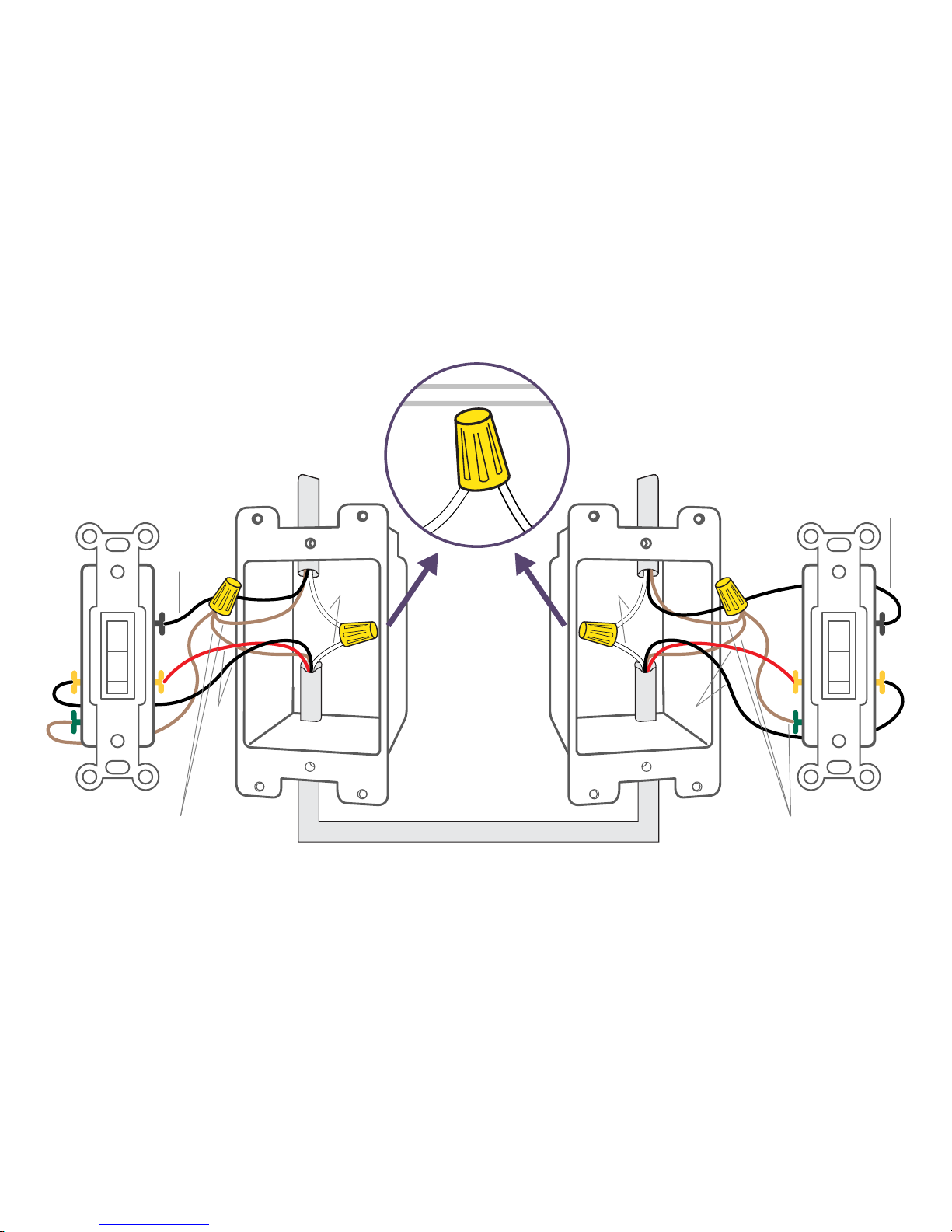
INSTALLATION - 3-WAY
STEP 1
Turn OFF the power at the circuit breaker.
STEP 2
Remove the existing faceplates and switches from the gang boxes.
Take a photo of the existing wiring for future reference.
STEP 3
Conrm that each gang box contains a neutral wire (typically white).
If there are no neutral wires present, you may need to run additional
wires, please consult a qualied electrician.
NOTE: Your home’s wiring may differ; please consult a qualied electrician.
Page 23
23
TRAVELER
(Usually Black or Red)
TRAVELER
(Usually Black or Red)
NEUTRAL
(Usually White)
NEUTRAL
(Usually White)
LINE
(Usually Black)
LOAD
(Usually Black)
GROUND
(Usually Bare Copper or Green)
GROUND
(Usually Bare Copper or Green)
Page 24

24
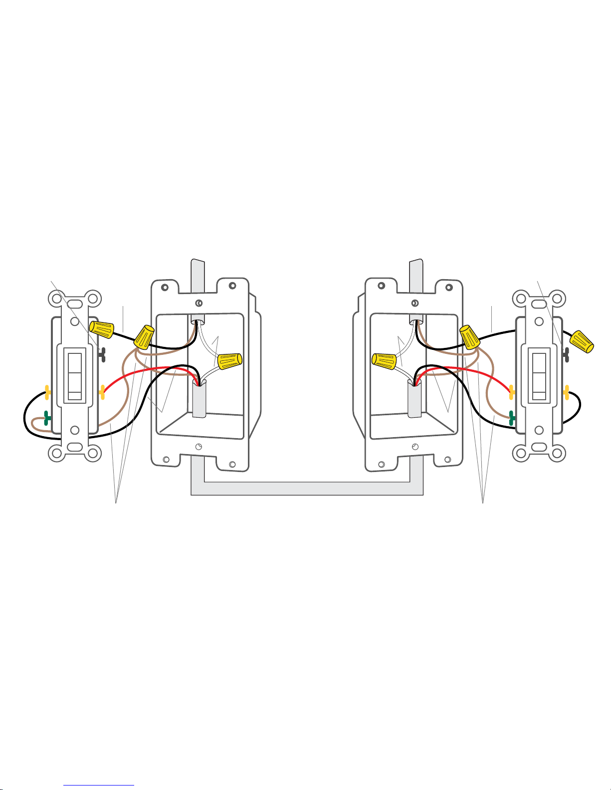
STEP 4
Remove the wires from the common terminal on both of the existing
switches and cap with the provided wire nuts. Note: The common
terminals usually have a screw that is either black or copper in color.
NOTE: Your home’s wiring may differ; please consult a qualied electrician.
Page 25
25
GROUND
(Usually Bare Copper or Green)
GROUND
(Usually Bare Copper or Green)
LINE
(Usually Black)
COMMON
TERMINAL
LOAD
(Usually Black)
TRAVELER
(Usually Black or Red)
TRAVELER
(Usually Black or Red)
NEUTRAL
(Usually White)
NEUTRAL
(Usually White)
COMMON
TERMINAL
Page 26

26
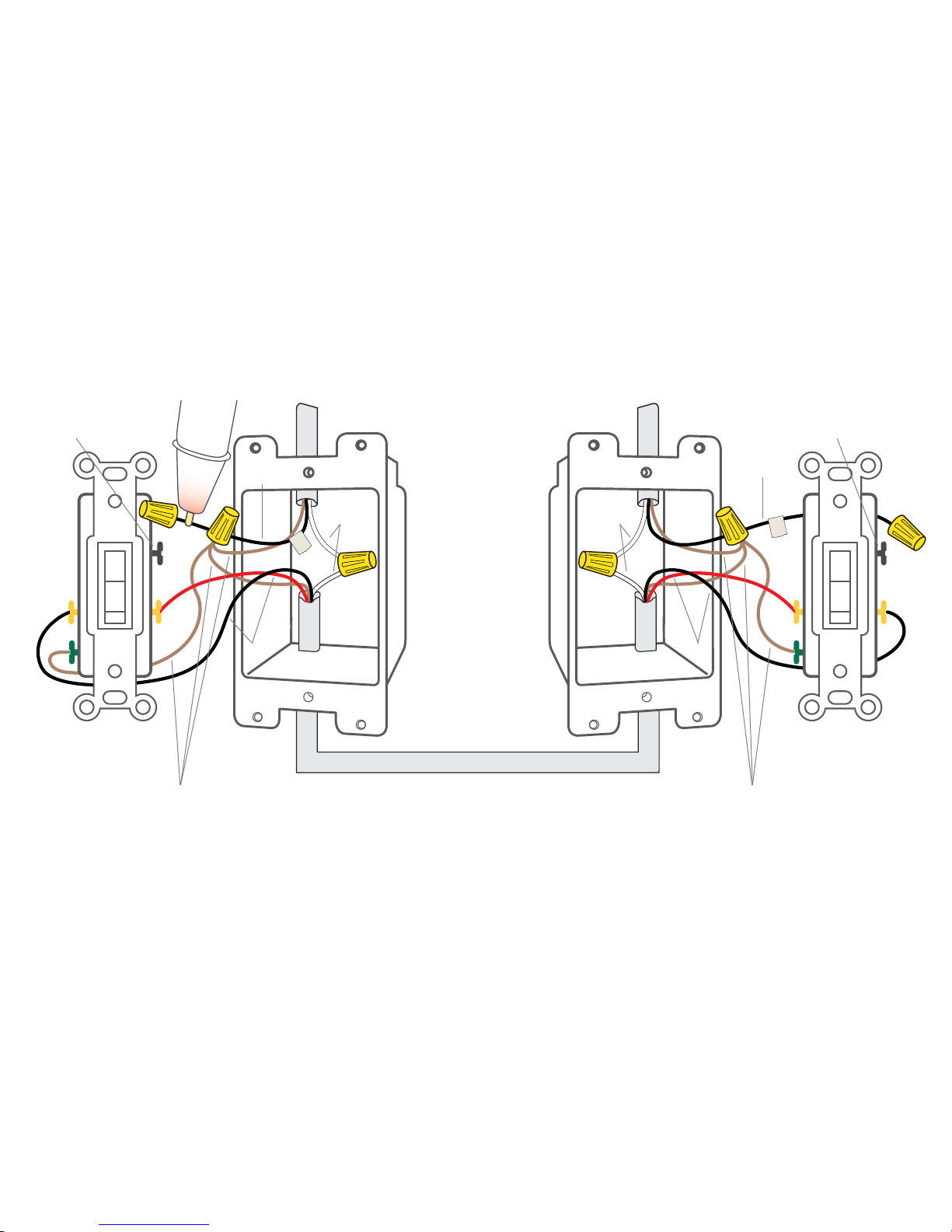
STEP 5
Turn the power back ON at the breaker. Using your voltage detector,
identify which of the two wires you removed from the common
terminal is energized. This is the “line” wire. Mark this wire as the
Secondary (S) Switch Position. You will need to refer to this during
the Wireless Communication Setup.
The wire you removed from the common terminal that is not
energized is the “load” wire. Mark as the Primary (P) Switch Position.
You will need to refer to this during the Wireless Communication
Setup.
NOTE: Your home’s wiring may differ; please consult a qualied electrician.
Page 27
27
S
P
TRAVELER
(Usually Black or Red)
GROUND
(Usually Bare Copper or Green)
NEUTRAL
(Usually White)
GROUND
(Usually Bare Copper or Green)
TRAVELER
(Usually Black or Red)
NEUTRAL
(Usually White)
COMMON
TERMINAL
COMMON
TERMINAL
LINE
(Usually Black)
LOAD
(Usually Black)
Page 28

28
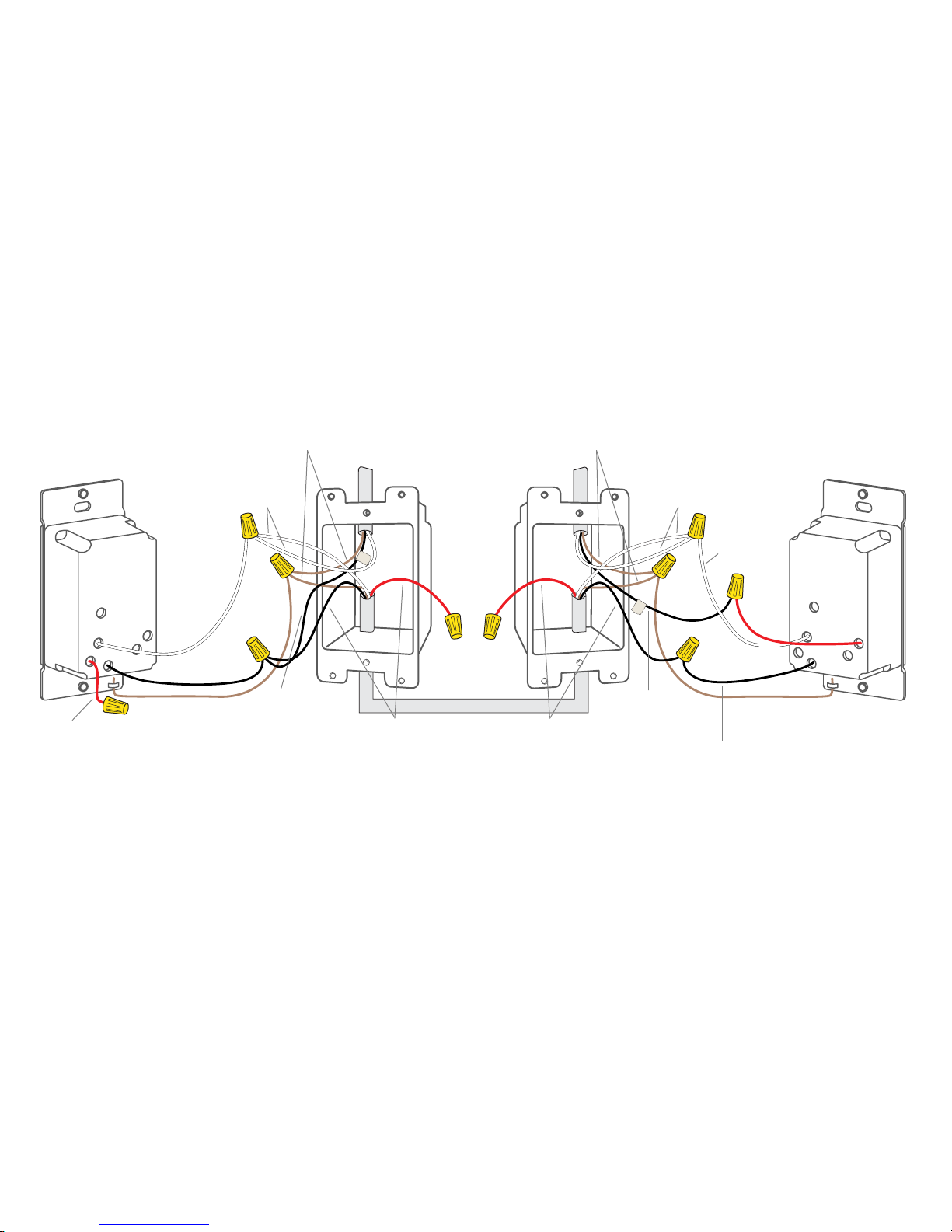
STEP 6
Install the iDevices® Wall Switches according to the diagram. Ensure
the wire nuts are securely fastened.
NOTE: Your home’s wiring may differ; please consult a qualied electrician.
Page 29
29
Ensure you install a wire nut on the red wire on the Secondary Switch
as well as on both ends of the unused traveler wire (typically red wire)
S
P
LINE
(Black)
LINE
(Black)
LOAD
(Usually Black)
SECONDARY SWITCH PRIMARY SWITCH
NEUTRAL
(Usually White)
NEUTRAL
(Usually White)
NEUTRAL
(White)
NEUTRAL
(White)
TRAVELER
(Usually Black or Red)
TRAVELER
(Usually Black or Red)
GROUND
(Bare Copper)
GROUND
(Bare Copper)
GROUND
(Usually Bare Copper or Green)
GROUND
(Usually Bare Copper or Green)
LINE
(Usually Black)
LOAD
(Red)
LOAD
(Red)
Page 30

30
STEP 7
Install the Wall Switches into the gang boxes and install the
faceplates.
STEP 8
Extend the pull out tab on the front of the Wall Switch connected to
the line wire (identied in step 5). Using a ballpoint pen, put an “X”
in the box to indicate that this is the Secondary Switch.
Page 31
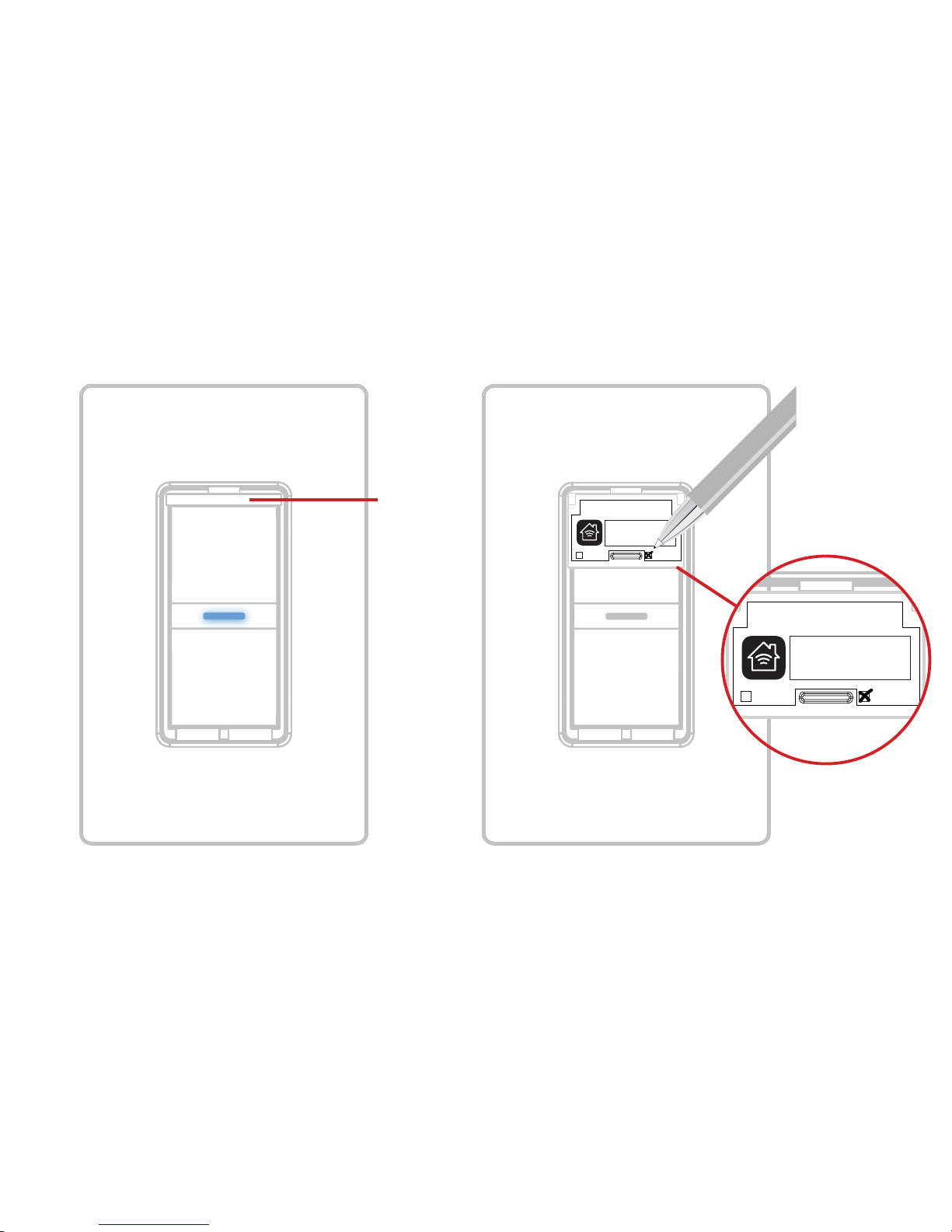
31
Wall Switch - Model: IDEV0008
Primary Secondary
XXX-XX-XXXX
Pull out
tab
Wall Switch - Model: IDEV0008
Primary Secondary
XXX-XX-XXXX
Page 32

32
STEP 9
Extend the pull out tab on the front of the Wall Switch connected to
the load wire (identied in step 5). Using a ballpoint pen, put an “X”
in the box to indicate that this is the Primary Switch.
STEP 10
Turn the power back ON at the circuit breaker and conrm that the
LED on both Wall Switches light up purple.
Page 33
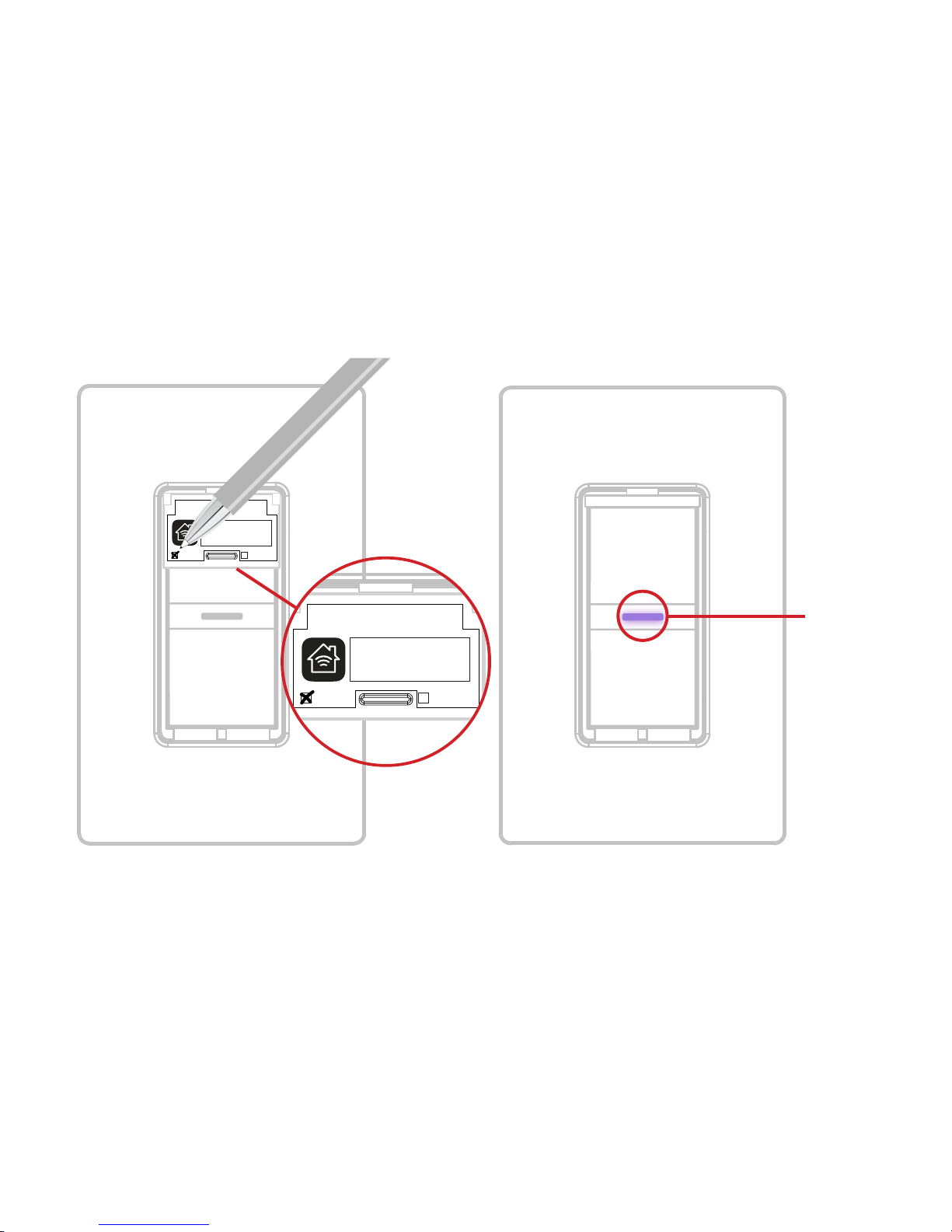
33
Wall Switch - Model: IDEV0008
Primary Secondary
XXX-XX-XXXX
Ensure LED
is purple on
BOTH Wall
Switches
Wall Switch - Model: IDEV0008
Primary Secondary
XXX-XX-XXXX
Page 34

34
WIRELESS COMMUNICATION SETUP
The wireless setup is a two-step process for a 3-way Switch
conguration. First you will pair the Primary Switch to the Secondary
Switch, then you will add the Primary Switch to your Wi-Fi® network.
PAIRING THE PRIMARY TO THE SECONDARY SWITCH
STEP 1
Ensure power/breaker is turned back ON and the LED on both Wall
Switches are solid purple.
Page 35
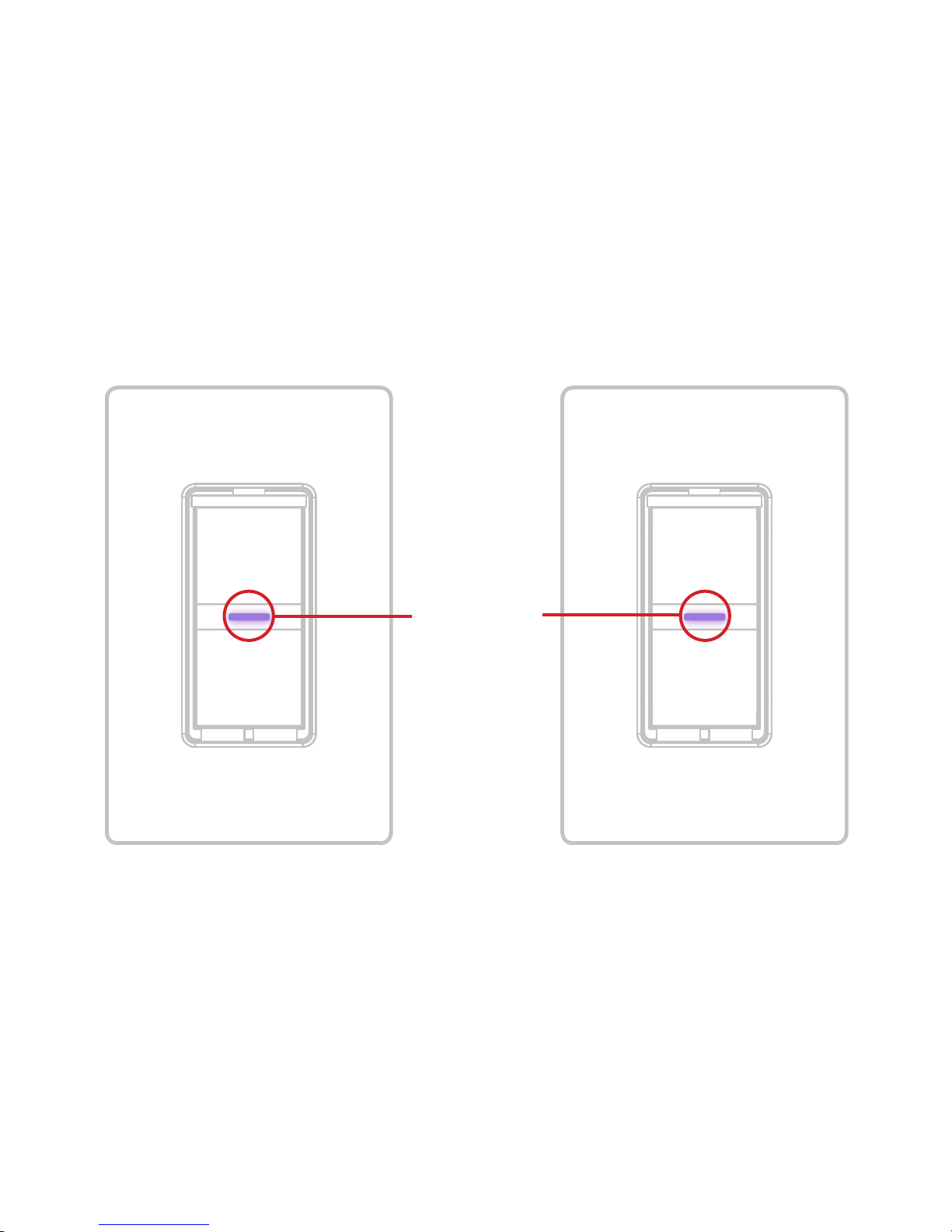
35
Ensure LED
is purple on
BOTH Wall
Switches
Page 36

36
STEP 2
Locate the Primary Switch. Hold “6” until the LED rapidly ashes
blue (3 seconds) then release. Next tap “1” to enter pairing mode.
The LED will slowly ash blue.
Next locate the Secondary Switch. Repeat the steps above on the
Secondary Switch by holding “6” until the LED rapidly ashes blue
(3 seconds) then release. Next tap “1” to begin the pairing mode.
The LED will ash blue slowly.
The Secondary Wall Switch will search and pair to the Primary
Switch. The LED on each Wall Switch will rapidly blink green 5
times and each Wall Switch will beep 5 times to indicate the pairing
process is complete.
Page 37
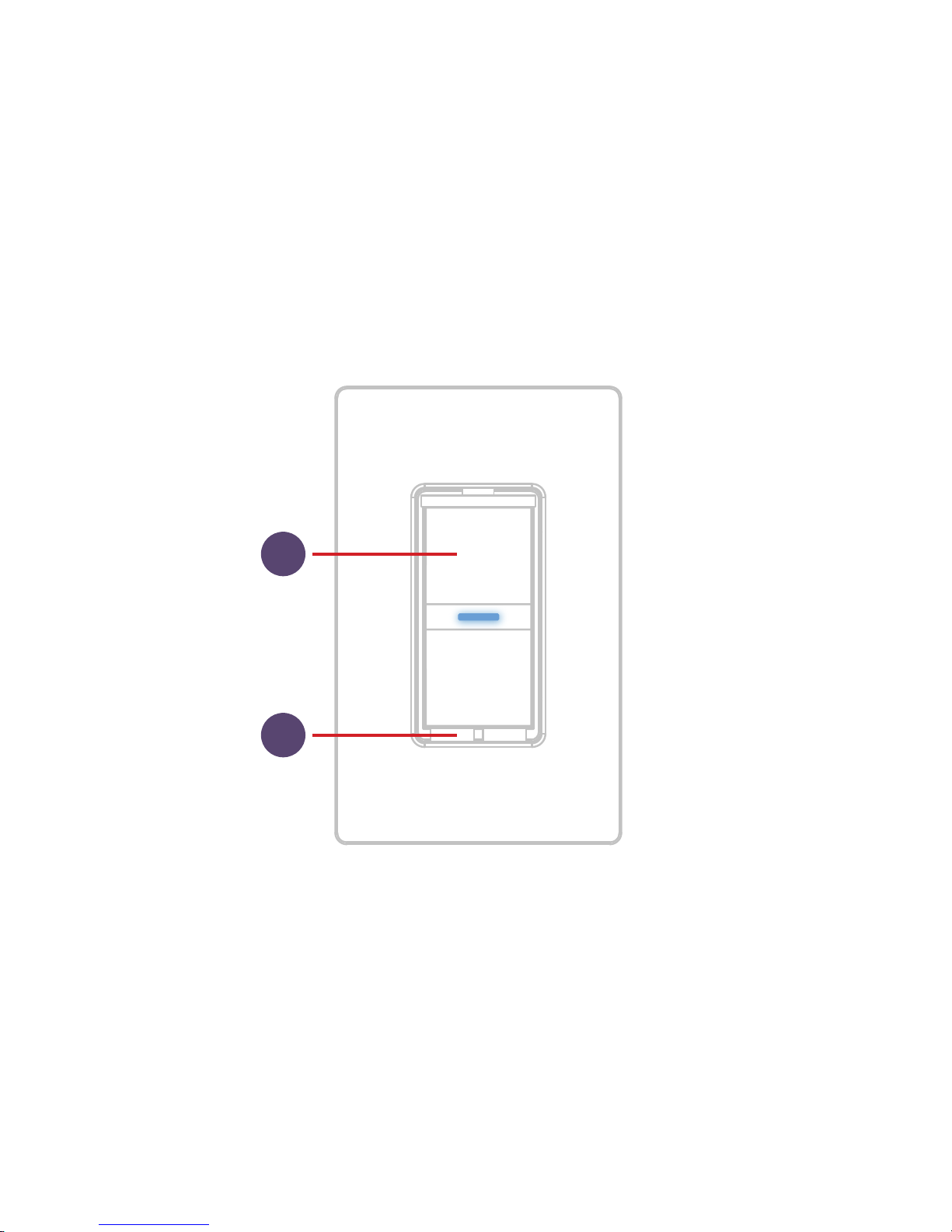
37
6
1
Page 38

38
CONNECTING TO THE
WIRELESS NETWORK
STEP 1
On the Primary Switch press and hold “6” for 3 seconds and release
when the LED rapidly ashes blue. Next Tap “2” to begin the Wi-Fi®
connection process.
Page 39
39
Ensure LED
is purple
2
6
Page 40
40
STEP 2
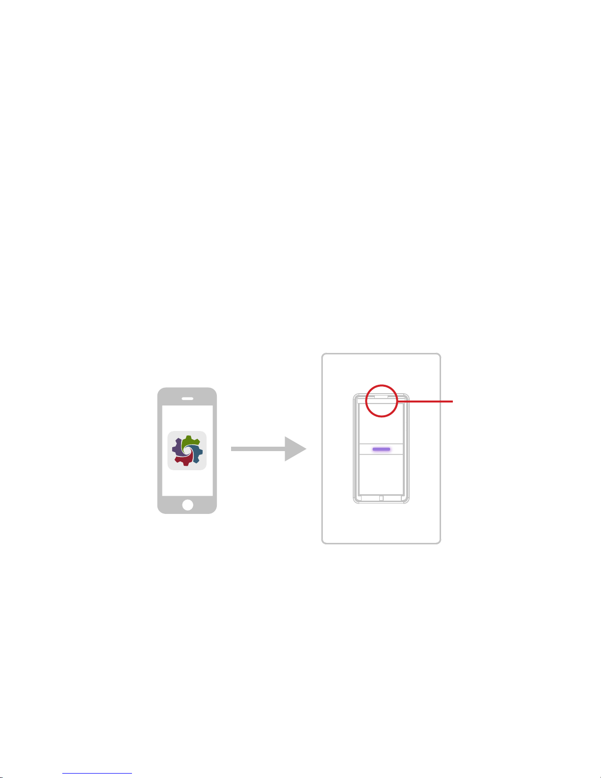
Launch the iDevices® Connected app and you will be guided
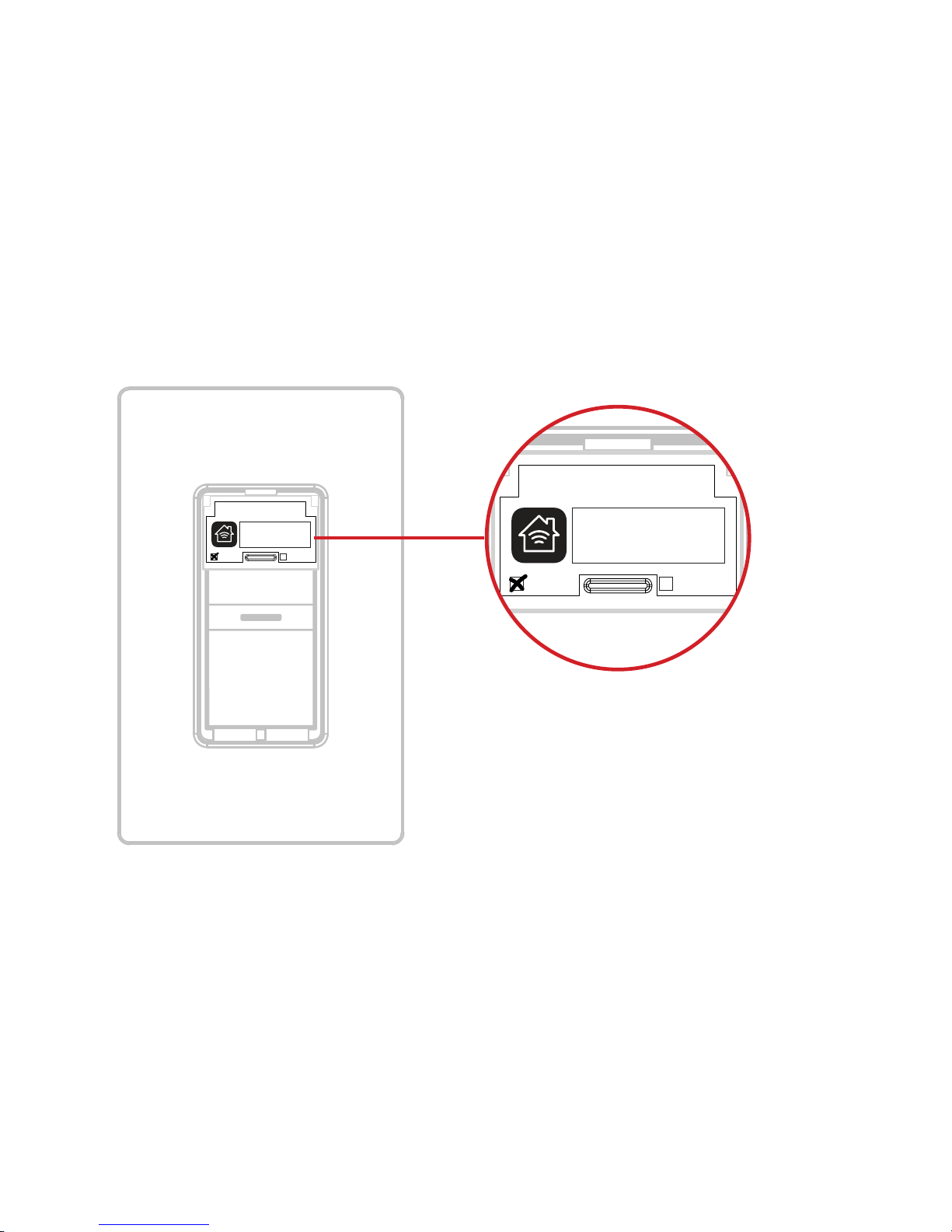
through the process of connecting your wall switches. For iOS
devices, you will need the HomeKit™ setup code on the pull out tab
of your Primary Wall Switch.
Icon
Pull out tab
Page 41
41
Wall Switch - Model: IDEV0008
Primary Secondary
XXX-XX-XXXX
HomeKit™ setup code is located on the
pull out tab of the iDevices® Wall Switch
Wall Switch - Model: IDEV0008
Primary Secondary
XXX-XX-XXXX
Page 42
42
REFERENCE INFORMATION
LED COLOR CODES
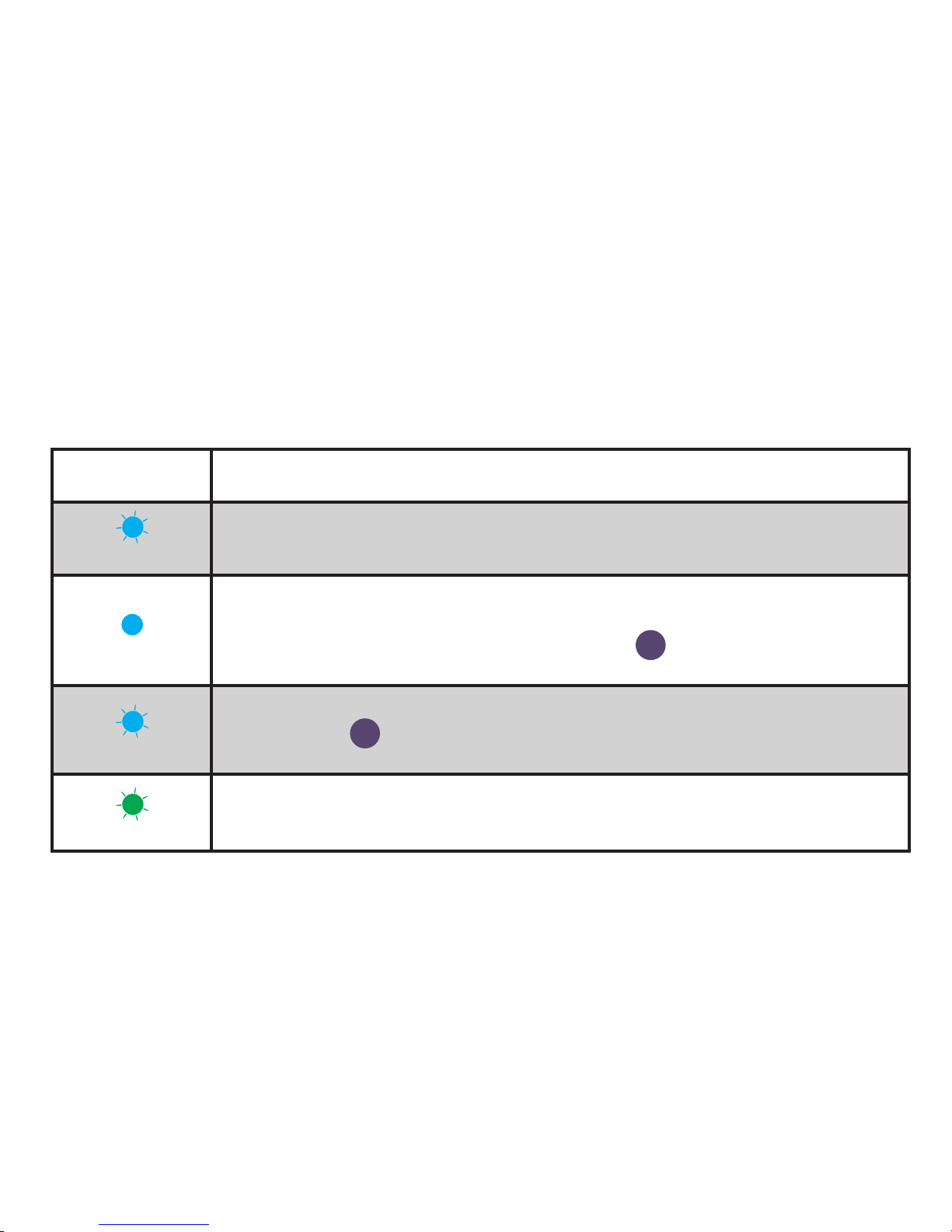
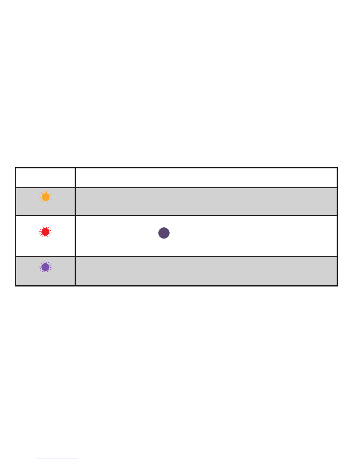
LED State Description
Blue Flash
Wall Switch is waiting for the handset to congure the accessory’s
Wi-Fi®. The LED ashes blue.
Solid Blue
Wall Switch is waiting for the mobile device to initiate and complete pair set
up. The LED is solid blue. Note: Pairing mode expires after 30 minutes; to
reinitiate pairing mode, press the Pairing Button 6 down for 3 seconds and
the LED will turn solid blue again.
Slow Blue Flash
Pairing mode has expired and Wall Switch is waiting for the user to press the
Pairing Button 6 down for about 3 seconds to re-enter pairing mode. The
LED slowly ashes blue.
Green Flash
When Wall Switch joins a Wi-Fi® network, (e.g., the link is up) the LED ashes
green for 1 second.
Page 43
43
LED State Description
Orange Flash
When Wall Switch has lost the connection to the Wi-Fi® network, (e.g., the link
is down) the LED slow ashes orange until the link is up.
Red Flash
To initiate a device reset, which will clear all Wi-Fi® and pairing information,
press the Pairing Button 6 down for 10 seconds until the LED rapidly ashes
red. When the button is released the unit will reboot and re-enter the pairing
mode.
Purple Flash
When Wall Switch receives a request to identify itself, or a software update is
being performed, it ashes purple.
Page 44

44
SUPPORT
If at any time you require assistance, please contact our
Customer Experience Team.
Call: 888.313.7019
Email: [email protected]
Visit: iDevicesinc.com/Support
Page 45

45
TROUBLESHOOTING AND SUPPORT
A DEVICE RESET CAN RESOLVE MOST ISSUES. Press and hold
6
(Pairing Setup Button) for 10 seconds until LED blinks red.
Page 46

46
REGULATORY INFORMATION
Product Information:
Manufacturer: iDevices® LLC
Model: IDEV0008
FCC: 2ABDJ-SWITCH8
IC: 11569A-SWITCH8
The iDevices® Wall Switch IDEV0008 is certied to comply with applicable
FCC and IC rules and regulations governing RF and EMI emissions.
This device complies with Part 15 of the FCC Rules. Operation is subject
to the following two conditions: (1) This device may not cause harmful
interference, and (2) This device must accept any interference received,
including interference that may cause undesired operation.
Page 47

47
FCC Notice
This equipment has been tested and found to comply with the limits for a
Class B digital device, pursuant to Part 15 of the FCC Rules. These limits are
designed to provide reasonable protection against harmful interference in a
residential installation.
This equipment generates, uses, and can radiate radio frequency energy
and, if not installed and used in accordance with the instructions may
cause harmful interference to radio communications. However, there is no
guarantee that interference will not occur in a particular installation. If this
equipment does cause harmful interference to radio or television reception,
which can be determined by turning the equipment off and on, the user is
encouraged to try to correct the interference by one or more of the following
measures:
Page 48

48
• Reorient or relocate the receiving antenna.
• Increase the separation between the equipment and receiver.
• Connect the equipment into an outlet on a circuit different from that to
which the receiver is connected.
• Consult the dealer or an experienced radio/TV technician to help.
• Changes or modications not expressly approved by the party responsible
for compliance could void the user’s authority to operate the equipment.
IC Notice
This Class B digital apparatus complies with Canadian ICES-003.
Cet appareil numérique de la classe B est conforme à la norme NMB003 du Canada. Le présent appareil est conforme aux CNR d’Industrie
Canada applicables aux appareils radio exempts de licence. L’exploitation
est autorisée aux deux conditions suivantes : (1) l’appareil ne doit pas
produire de brouillage, et (2) l’utilisateur de l’appareil doit accepter tout
brouillage radioélectrique subi, même si le brouillage est susceptible d’en
Page 49

49
compromettre le fonctionnement.
This device complies with the Industry Canada license exempt RSS
standard(s). Operation is subject to the following two conditions: (1) this
device may not cause interference, and (2) this device must accept any
interference, including interference that may cause undesired operation of
the device.
References
Requires the iDevices® Connected app. For warranty information please visit
iDevicesinc.com/Warranty.
Page 50
50
Apple, the Apple logo, iPhone, and iPod touch are trademarks of Apple
Inc., registered in the U.S. and other countries. App Store is a service mark
of Apple Inc. HomeKit is a trademark of Apple Inc. Controlling HomeKitenabled accessories away from home requires an Apple TV (3rd generation
or later) with Apple TV software 7.0 or later and an iPhone, iPad, or iPod
touch with iOS 8.1 or later. Amazon, Echo, Alexa and all related logos are
trademarks of Amazon.com, Inc. or its afliates. Android is a trademark of
Google Inc. Google Play and the Google Play logo are trademarks of Google
Inc. The Bluetooth® word mark and logos are registered trademarks owned
by the Bluetooth SIG, Inc. and any use of such marks by iDevices is under
license. Other trademarks and trade names are those of their respective
owners.
Page 51

iDevicesinc.com
 Loading...