

Welcome To
INSTALLATION GUIDE
1

Contents
Introduction ........................................................ 3
In The Box .......................................................... 4
Display ................................................................ 5
Before You Start .................................................. 6
Installation Overview .......................................... 7
Professional Assistance ....................................... 7
Abbreviations ..................................................... 8
Installation Details ............................................ 10
Wiring Chart ..................................................... 11
Connecting To The App
And Wi-Fi® Network ......................................... 14
Conguring The Thermostat
For Your HVAC System ..................................... 15
Set In-App Preferences ..................................... 15
Wiring Conguration ........................................ 18
Troubleshooting & Support .............................. 31
Introduction
From removing your old thermostat, to installing
your new iDevices
®
Thermostat, this easy-tofollow guide will take you through the process,
step by step.
If at any time you require assistance, please
contact our Customer Experience Team.
Call: 888.313.7019
Monday – Friday
8am – 8pm EST
Email: Support@iDevicesinc.com
Visit: iDevicesinc.com/Support
Please visit iDevicesinc.com/Compatiblity to
see if your HVAC system is compatible.
2 3
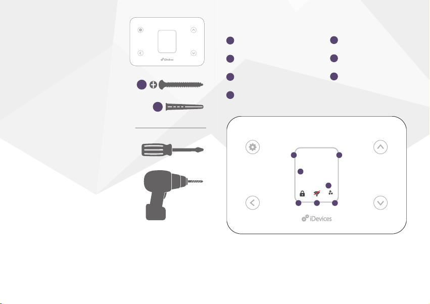
In The Box
- iDevices® Thermostat
- Mounting Hardware
Requires
- Home Wi-Fi® Network
- Free iDevices®
Connected App
- 24VAC Common Wire
- Compatible Mobile Device
(Visit iDevicesinc.com/
Compatibility)
Display
1
System Mode
2
Ambient Temperature
3
x2
x2
Desired Temperature
4
HVAC State
5
Button Lock
6
Connection Status
7
Fan Mode
Tools
- Phillips Screwdriver
- Drill With 3/16” Bit
80
Cooling
o
2
76
o
4
AUTO
765
AUTO
1
3
4 5

Before You Start
1. Read through this Installation Guide in its
entirety before starting installation of your
iDevices® Thermostat or removal of your
old thermostat. Incorrect installation can be
dangerous and can damage your iDevices
Thermostat and HVAC system. If you’re not
®
comfortable performing the installation,
contact a local HVAC contractor.
2. Turn the power to your HVAC system
and old thermostat OFF!
3. Ensure you do not have electric baseboard
heating. The iDevices® Thermostat is not
compatible with these systems.
4. Check that your mobile device is compatible
with the iDevices® Thermostat at
iDevicesinc.com/Compatibility.
5. If this is a new installation, you will need to
install the iDevices
®
Thermostat 4 – 5 feet
above the oor, in accordance with applicable
building codes. It should be installed in an
area with good airow. Avoid areas behind
doors, near corners, heating or cooling
vents, heat generating devices, or
direct sunlight. This Transmitter must be installed to
provide a separation distance of at least 20 cm from all persons
6 7
Installation Overview
1. Turn the power to your HVAC system OFF!
2. Remove the faceplate of your old thermostat
and photograph the existing
wiring conguration.
3. Disconnect your old thermostat’s wall
plate and secure the wires.
4. Mount your iDevices® Thermostat mounting
plate and attach wires to match your
system’s conguration.
5. Attach your iDevices® Thermostat to the
mounting plate.
6. Turn the power back ON.
7. Download the free iDevices® Connected app.
8. Connect your iDevices® Thermostat to your
home network and pair it to your iDevices®
Connected app.
9. Set up and customize your iDevices®
Thermostat within the iDevices®
Connected app.
Professional Assistance
Your safety comes rst! If you don’t feel
comfortable installing your iDevices® Thermostat,
contact a local HVAC contractor.
Abbreviations
HVAC: Heating, Ventilation, and Air
Conditioning system
HP: Heat Pump System. This type of HVAC
system uses a compressor with a reversing valve
to provide both heating and cooling capability.
HE: Electrically heated central heating system.
This system uses an electric heating element
along with a fan and ducting. Sometimes used as
AUX/Emergency heat with a heat pump system.
Electric baseboard heaters are not included in this
system type.
HG: Fuel-red central heating system. This system
uses a gas or oil burner along with a fan and
ducting, or a hot water baseboard system. Can be
used as a standalone heating system or as AUX/
Emergency heat with a heat pump system.
O/B: This option selects the type of reversing
valve for heat pump systems. An “O” reversing
valve is energized when cooling, and a “B”
reversing valve is energized when heating.
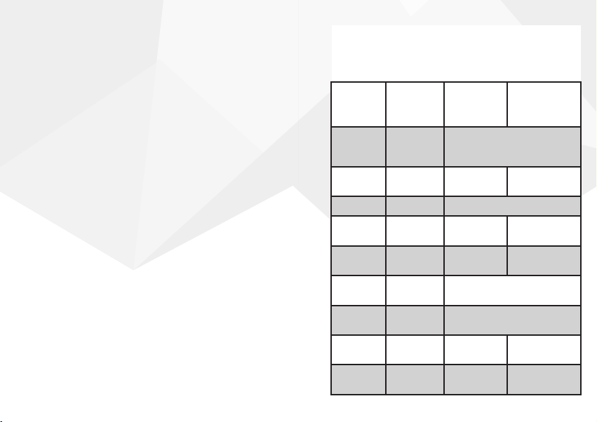
Terminal Assignments
For reference, standard wiring assignments for
typical HVAC systems are provided below.
Terminal
(HP)
C C 24VAC common for control
L L System
G G Fan
Y1 Y1 1st stage
Y2 Y2 2nd stage
RC RC 24VAC power supply for cooling
RH RH 24VAC power supply for heating
O/B W1 Changeover
E W2 Emergency/
Terminal
(Non-HP)
Heat Pump
System
(HP)
circuit and thermostat power
input
Monitor
compressor
compressor
side
side
valve
AUX heat
Conventional
System
(Non-HP)
Not used
1st stage
cooling
2nd stage
cooling
1st stage
heating
2nd stage
heating
8 9
Installation Details
1. Gather the tools you will need and check
that your iDevices
®
Thermostat came with the
necessary components (see page 4).
Do not select COOL mode if the outside temperature is below
50ºF (10ºC). This could damage the cooling system.
Warnings And Safety Information
2. Test your existing system. Using your old
thermostat, turn on the heating/cooling
functions (if applicable) to verify everything is
functioning normally.
3. If you have a heat pump system, check the
settings on your old thermostat and make
a note whether you have an “O” or “B” type
reversing valve.
4. Turn the power to your HVAC system OFF at
the breaker box or the main switch controlling
your heating/cooling system.
5. Conrm that the power is OFF by adjusting
the temperature on your old thermostat and
waiting to ensure your system doesn’t turn on.
6. Carefully remove the faceplate of your
old thermostat.
7. Take a picture of your old thermostat’s wire
arrangement to reference later on.
8. Make note of the current locations of each
10 11
colored wire by lling out the Wiring Chart
below. Note: If you see any of the following
wires, please contact our Customer Experience
Team to check system compatibility:
A. W3
B. H/HUM
C. A, X or P
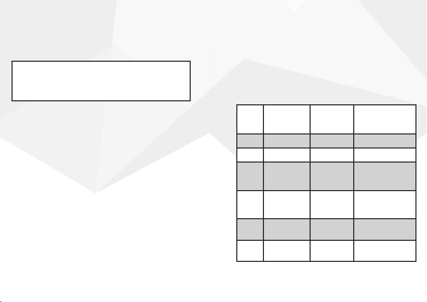
Wiring Chart
Label
HUM Not Used Humidier
NC Not Used
W2/E Brown 2nd stage heat/
W1/
O/B
RH Red Power from heat,
RC Red Power from cooling,
Old
Thermostat
Wire Color Description
AUX/Emergency
Heat
White/
Orange/
Blue
1st stage heat/HP
reversing valves
24VAC transformer
24VAC transformer

Label
Y2 Grey Stage 2 compressor
Y1 Yellow Stage 1 compressor
G Green Fan relay
L System monitor
C Black/Blue Common of 24VAC
Old
Thermostat
Wire Color Description
relay
relay
transformer
around a pen). Remove the mounting plate
from the wall.
12. Line up the iDevices
®
Thermostat mounting
plate on the wall in the desired location.
Check that it is level and the wires are in
a position to t through the hole on the
mounting plate. Use a pencil to mark anchor
locations on the wall.
9. Make sure you don’t have
any 120/240V wires (look
for thick black wires with wire
nuts.) If you do, the iDevices®
Thermostat is not compatible
with your system. If you’re
not sure, call us at
888.313.7019.
10. Record the locations of any jumpers
and note whether there is a wire
connected to RC and/or RH.
11. Disconnect the wires from the existing
mounting plate (ensure the wires don’t fall
back into the wall by gently wrapping them
!
13. Set the mounting plate aside. Drill two holes
(3/16” diameter) at the locations you
have marked.
14. Install the provided anchors into the wall, line
up the mounting plate to those holes and
install with the provided screws.
15. Head to the Wiring Conguration section,
starting on page 18, to nd the conguration
that matches closest to your old thermostat
and note which system you have for later
reference.
12 13

16. Connect the wires to the mounting plate
based on the information you gathered in
the chart on pages 11-12, photos you took
earlier and wiring conguration you noted
for step 15.
17. To prevent electrical shorts and damage to
your iDevices
®
Thermostat or home, ensure
all of the wire connections are secure
and there are no bare wires in contact with
another. Insulate bare wires with electrical
tape as necessary. Push any excess wire back
into the wall cavity.
18. Attach your iDevices
®
Thermostat to the
mounting plate.
19. Turn your power on at the breaker box or
switch that controls your heating/cooling
system.
20. Your iDevices® Thermostat will automatically
turn on and display the “Connecting
Thermostat to Network” screen.
Note: The Thermostat will stay in the
connection mode for 30 minutes before
timing out. You can manually enter this mode
from the Settings > Setup > Connect menu.
Connecting To The App And Wi-Fi® Network
1. Download and launch the free iDevices®
14 15
Connected app on your mobile device.
2. From the iDevices® Connected app, add the
Thermostat by tapping on the menu bar in
the upper right-hand corner.
3. Follow the instructions in the app to
complete the connection process.
Conguring The Thermostat For
Your HVAC System
1. Refer to Thermostat Settings for your system
conguration, starting on page 8.
2. Press the button on your
iDevices® Thermostat.
3. Use the
and press the button to select.
4. Use the
and press the button to select.
buttons to scroll to ‘Setup’
buttons to scroll to ‘HVAC TYPE’
5. Using the buttons to scroll and the
button to select, set the Stage and Type for
your system conguration (A through L).
6. If you have a heat pump, set O/B Type to
what you recorded earlier.
7. Your iDevices
®
Thermostat is now congured.
Set In-App Preferences
In your iDevices® Connected app, select the

Thermostat on the home screen. Tap the ‘Menu’
button in the upper left-hand corner. From
here, you can edit the details of your iDevices
®
Thermostat, organize it into a ‘Room’ and ‘Zone’,
set schedules and create ‘Scenes’.
Do not short across terminals on the gas valve or at
the heating or cooling system control board to test the
thermostat installation. This could damage the thermostat
and void the warranty.
Do not select COOL mode if the outside temperature is
below 50ºF (10ºC). This could damage the controlled
cooling system.
Warnings And Safety Information
Testing Your System
1. Set your iDevices® Thermostat to HEAT
mode. Adjust the temperature set point
above the ambient temperature in the room,
and verify that the heat turns on.
2. Set your iDevices® Thermostat to COOL
mode (if outside temperature is above
50ºF). Adjust the temperature set point
below the ambient temperature in the room,
and verify that the cooling turns on.
3. If your system has dual fuel sources (heat
pump plus electric or fuel-red emergency
heat), set your iDevices® Thermostat
to EMERGENCY HEAT mode. Adjust the
temperature set point above the ambient
temperature in the room, and verify that the
heat turns on.
4. Note: If you have a heat pump or air
conditioner, the iDevices® Thermostat is
designed to prevent damage to your
compressor by waiting 5 minutes between
restarts of your air conditioner or heat pump.
If you are testing the operation of your air
conditioner or heat pump, wait at least 5
minutes after changing the temperature
setting for the system to turn on.
5. If all of the available system modes function
properly, the test is complete.
16 17

Wiring Congurations
Note: G wire is not required for hot water baseboard or steam radiator systems. If G wire is
not connected for a warm air heating system, Fan On mode will not be available.
The following section provides the various
wiring congurations compatible with the
®
iDevices
Thermostat. Find the conguration that
matches closely to your old thermostat and note
which system type you have for later reference.
Check your old thermostat to see if it has one or
two Red/R wires. If you have two, connect one
to RC, one to RH, and remove the jumper. If you
have one R wire, connect it to RH and leave the
jumper in place.
If your system has two R wires,
either RC and RH, or R and RC:
Remove Jumper
between RC and RH
Y1
G
W1/O/B
W2/E
NC
RH
RC
Y2
If your system has one R wire:
Keep Jumper
between RC and RH
Y2
Y1
G
RC
A. Heat Only (One Stage)
Note: G wire is not required for hot-water baseboard or
steam radiator systems. If G wire is not connected for a warm
air heating system, Fan On mode will not be available.
Thermostat Settings
RC
Y2
Y1
G
C
L
W1/O/B
W2/E
HUM
NC
RH
RH
W1/O/B
W2/E
Stage: Non-HP | Type: HE for electric, HG for gas/oil
systems | Fan wire G optional for HG type
NC
18 19

B. Heat Only (Two Stages)
Note: G wire is not required. However, if G wire is not connected, Fan On mode will not be
available.
Note: G wire is not required for hot water baseboard or steam radiator systems. If G wire is
not connected for a warm air heating system, Fan On mode will not be available.
Note: G wire is not required for hot-water baseboard or
steam radiator systems. If G wire is not connected for a warm
air heating system, Fan On mode will not be available.
Stage: Non-HP | Type: HE for electric, HG for gas/oil
systems | Fan wire G optional for HG type
Thermostat Settings
RC
Y2
Y1
G
C
L
RH
W1/O/B
W2/E
HUM
NC
C. Cool Only (One Stage)
Stage: Non-HP | Type: HG
Thermostat Settings
RC
Y2
Y1
G
C
L
W1/O/B
W2/E
HUM
NC
RH
20 21

D. Cool Only (Two Stages) E. Heat (One Stage) and Cool (One Stage)
Note: G wire is not required. If G wire is not connected, Fan On mode will not be available.
Note: G wire is not required. However, if G wire is not connected, Fan On mode will not be
available.
Stage: Non-HP | Type: HG
Thermostat Settings
RC
Y2
Y1
G
C
L
RH
W1/O/B
W2/E
HUM
NC
Stage: Non-HP | Type: HE for electric, HG for
gas/oil systems
Thermostat Settings
RC
Y2
Y1
G
C
L
RH
W1/O/B
W2/E
HUM
NC
22 23

F. Heat (Two Stages) and Cool (One Stage) G. Heat (One Stage) and Cool (Two Stages)
Note: G wire is not required. If G wire is not connected, Fan On mode will not be available.
Note: G wire is not required. If G wire is not connected, Fan On mode will not be available.
Stage: Non-HP | Type: HE for electric, HG for
gas/oil systems
Thermostat Settings
RC
Y2
Y1
G
C
L
RH
W1/O/B
W2/E
HUM
NC
Stage: Non-HP | Type: HE for electric, HG for
gas/oil systems
Thermostat Settings
RC
Y2
Y1
G
C
L
W1/O/B
W2/E
HUM
NC
RH
24 25

H. Heat (Two Stages) and Cool (Two Stages) I. Heat Pump (One Stage)
Note: G wire is not required. If G wire is not connected, Fan On mode will not be available.
Note: G wire is not required. If G wire is not connected, Fan On mode will not be available.
Stage: Non-HP | Type: HE for electric, HG for
gas/oil systems
Thermostat Settings
Stage: HP | Type: HG | O/B Type: According to
previous thermostat setting
Thermostat Settings
W1/O/B
W2/E
HUM
NC
RH
RC
Y2
Y1
G
C
L
W1/O/B
W2/E
HUM
NC
RH
RC
Y2
Y1
G
C
L
26 27

J. Heat Pump (One Stage with AUX/
Note: G wire is not required. If G wire is not connected, Fan On mode will not be available.
Note: G wire is not required. If G wire is not connected, Fan On mode will not be available.
Emergency Heat)
Stage: HP | Type: HE for electric, HG for gas/oil
systems | O/B Type: According to previous
thermostat setting
Thermostat Settings
RC
Y2
Y1
G
C
L
RH
W1/O/B
W2/E
HUM
NC
K. Heat Pump (Two Stages)
Stage: HP | Type: HG | O/B Type: According
to previous thermostat setting
Thermostat Settings
RC
Y2
Y1
G
C
L
RH
W1/O/B
W2/E
HUM
NC
28 29

L. Heat Pump (Two Stages with AUX/
Note: G wire is not required. If G wire is not connected, Fan On mode will not be available.
Emergency Heat)
Stage: HP | Type: HE for electric, HG for gas/oil
systems | O/B Type: According to previous
thermostat setting
Thermostat Settings
RC
Y2
Y1
G
C
L
W1/O/B
W2/E
HUM
NC
RH
Troubleshooting & Support
If your Thermostat doesn’t connect to your
network or app on the rst try, hold the reset
button on the right side for 3 seconds using
a paperclip.
Call or email the iDevices® Customer Experience
Team with questions.
Call: 888.313.7019
Monday – Friday
8am – 8pm EST
Email: Support@iDevicesinc.com
Visit: iDevicesinc.com/Support
30 31


 Loading...