

R&D
Access Touch 2.0 – User Manual
Version 1.03
Public 1 (12)
Author: Hal File: C00320E Date: 18.8.2012
Approved: Jpo Printed: 20.08.2012 09:45
Idesco Oy | Teknologiantie 9, FIN-90590 OULU | Tel +358 20 743 4175 | info@idesco.fi | www.idesco.fi
User Manual
Access Touch 2.0
Version Date Author Description
1.00 19.07.2010 Jpo First version
1.01 21.12.2010 Jpo FET output descriptions made clearer
1.02 04.02.2011 Jpo Reset button added
1.03 18.08.2012 Hal Shutdown instructions added

R&D
Access Touch 2.0 – User Manual
Version 1.03
Public 2 (12)
Author: Hal File: C00320E Date: 18.8.2012
Approved: Jpo Printed: 20.08.2012 09:45
Idesco Oy | Teknologiantie 9, FIN-90590 OULU | Tel +358 20 743 4175 | info@idesco.fi | www.idesco.fi
1. Purpose of this user manual ....................................................................................................... 3
2. Description of Access Touch 2.0 ................................................................................................ 3
3. Package content ........................................................................................................................... 3
4. Notes ............................................................................................................................................. 3
5. Installation .................................................................................................................................... 4
5.1. Installation, mechanics ............................................................................................................ 4
5.2. Installation, electronics ............................................................................................................ 4
5.2.1. Connector 1 ..................................................................................................................... 5
5.2.2. Connector 2 ..................................................................................................................... 6
5.2.3. Connector 3 ..................................................................................................................... 7
5.2.4. Connector 4 ..................................................................................................................... 7
5.2.5. Connector 5 ..................................................................................................................... 8
5.2.6. Ethernet Connection ........................................................................................................ 8
5.2.7. USB Ports ........................................................................................................................ 8
5.2.8. Reset button..................................................................................................................... 9
5.3. Mounting ................................................................................................................................. 9
5.4. Booting .................................................................................................................................. 10
6. System shutdown ....................................................................................................................... 10
7. Dimensions ................................................................................................................................. 10
7.1. Front panel ............................................................................................................................ 10
7.2. Side measures ...................................................................................................................... 11
8. Technical data ............................................................................................................................ 11

R&D
Access Touch 2.0 – User Manual
Version 1.03
Public 3 (12)
Author: Hal File: C00320E Date: 18.8.2012
Approved: Jpo Printed: 20.08.2012 09:45
Idesco Oy | Teknologiantie 9, FIN-90590 OULU | Tel +358 20 743 4175 | info@idesco.fi | www.idesco.fi
1. Purpose of this user manual
The purpose of this manual is to guide you in installing Access Touch 2.0 screen terminal. After having completed the installation you can start creating your own customer specific applications with this
multi-use device.
2. Description of Access Touch 2.0
Access Touch 2.0 is a touch screen terminal that:
• Enables you to manage a wireless identification system
• Can also be used as an independent control unit
Access Touch 2.0 consists of an integrated computer module and an RFID reader. It can be used for
management of a wireless system or as an independent unit, for e.g. time and attendance, payment
applications, alarm control or as an info screen, etc. Access Touch 2.0 operates on the Linux
operating system, however Windows is also optional. Access Touch 2.0 includes a fully operating
integrated computer on module with good performance offering a variety of options for different types
of customised solutions. Access Touch 2.0 also has an integrated RFID reader unit, available with a
variety of technologies in 125 kHz and 13,56 MHz frequencies. The device can manage wireless
access control readers and wireless UHF readers, also offered by Idesco. The front panel is fully
customisable to your needs. The device consists primarily of a screen module with embedded
electronics and a back plate for installation.
3. Package content
• a fully integrated computer deploying Idesco Embedded Linux operating system or with Windows XP operating system
• an RFID reader unit with one of the following modules:
1. Access 7 C, supporting the following technologies (for UID reading): Philips Mifare®,
I-Code®, Inside PicoTag®and PicoPass®, HID iClass®, LEGIC Advant® and most
of the existing and forthcoming ISO15693 tags like Tag-it®, ST, Fujitsu, Infineon etc.
2. Access 8 CM t, supporting Mifare® technology with multi-application options
3. Access 8 CD, supporting Mifare® DESfire multi-application options
4. IR 6090B, supporting Idesco Microlog technology with read/write functions
5. Other RFID reader modules available optionally
• Other optional equipment depending on specific order requirements:
1. WLAN USB module
2. Idesco Cardea USB-stick (for wireless communication).
3. Additional SSD memory
4. NOTE! Two additional USB ports available with default HW-configuration
4. Notes
• Handle the unit, especially the front cover, with care.
• Handle the electronics with care to avoid any electrostatic discharges
• Keep all sharp or pointed objects (pens, screwdrivers, etc.) away from touchscreen surface
• Use a soft towel when cleaning the front panel
• It is strongly recommended to deploy a power back up (UPS) in tandem with Access Touch 2.0

R&D
Access Touch 2.0 – User Manual
Version 1.03
Public 4 (12)
Author: Hal File: C00320E Date: 18.8.2012
Approved: Jpo Printed: 20.08.2012 09:45
Idesco Oy | Teknologiantie 9, FIN-90590 OULU | Tel +358 20 743 4175 | info@idesco.fi | www.idesco.fi
5. Installation
NOTE! Power must be turned off from your VDC feeding device when making connections!
5.1. Installation, mechanics
Feed all necessary wires through the insert holes in the middle of the back cover (picture 1). Install
the back cover to the wall using the four mounting tracks show below (picture 1).
Picture 1: Note two cable egress ports provided in the middle of the back cover and the four mounting tracks
provided in the corners
5.2. Installation, electronics
Connect all necessary wires to the Access Touch 2.0 PCB (e.g VDC, GND, Relay control…)
Follow diagram in picture 2 below for locating different connector hubs. Each connector’s functions
are described separately in the following chapters. NOTE: It is highly recommended that you
deploy an independent power supply as a backup in the event of power interruptions.

R&D
Access Touch 2.0 – User Manual
Version 1.03
Public 5 (12)
Author: Hal File: C00320E Date: 18.8.2012
Approved: Jpo Printed: 20.08.2012 09:45
Idesco Oy | Teknologiantie 9, FIN-90590 OULU | Tel +358 20 743 4175 | info@idesco.fi | www.idesco.fi
CONNECT OR 1
CONNECTO R 2
CONNECT OR 3
CONNECT OR 4
CONNECT OR 5
ETHERNET CONNECT OR
USB 1
USB 2USB 3
Picture 2: Access Touch 2.0 connections
5.2.1. Connector 1
Connector 1 includes the power supply, RS485, and wiegand hubs
Picture 3: Connector 1
5.2.1.1. Power supply
Input voltage: 15...30 VDC
Power requirements / average current consumptions:
850 mA @ 15 VDC
520 mA @ 24 VDC
Choose a power supply that meets the above power requirements.
5.2.1.2. Wiegand hubs A and B
Two wiegand readers can be connected with the wiegand A and wiegand B hubs. Two open collector
outputs OUT A and OUT B may be used for controlling wiegand reader inputs (e.g. reader LED control)

R&D
Access Touch 2.0 – User Manual
Version 1.03
Public 6 (12)
Author: Hal File: C00320E Date: 18.8.2012
Approved: Jpo Printed: 20.08.2012 09:45
Idesco Oy | Teknologiantie 9, FIN-90590 OULU | Tel +358 20 743 4175 | info@idesco.fi | www.idesco.fi
Data from wiegand hubs is routed through the Access Touch 2.0 application controller. Consult the
separate Access Touch 2.0 Protocol Description for wiegand output / input controls.
Port data is read through the /dev/ttyS1 port in the Access Touch 2.0 Embedded Linux Operation
System.
5.2.1.3. RS485
T+, T-, R+ and R- connectors are used for connecting RS485 readers to the Access Touch 2.0.
Note: An RS485 application control protocol must be implemented in the Access Touch 2.0
operating system for RS485 readers to be detected by the Access Touch 2.0. For two wire
RS485 usage connect T+ and R+ pair and T- and R- pair together.
5.2.2. Connector 2
Connector 2 includes the RS232, speaker, microphone, power switch and I2C connections.
Picture 4: Connector 2
5.2.2.1. RS232_Reader (ATM)
RS232 ATM connection may be used to connect RS232 devices to the Access Touch 2.0. Note: By
default, any pre-installed Access Touch 2.0 internal reader uses this connection, Therefore you
should connect devices to this port only after any internal reader has been disconnected from it.
Data from this RS232 connection routes through the Access Touch 2.0 application controller.
Consult the separate Access Touch 2.0 Protocol Description for RS232 ATM device output.
Corresponding data routes through the /dev/ttyS1 port in the Access Touch 2.0 Embedded Linux
Operation System.
5.2.2.2. RS232_COM (ETX)
The RS232 ETX connection may be used when connecting a second RS232 device to the Access
Touch 2.0. This connection may also be used if the primary RS232 ATM port is unavailable. This
hub is connected directly to the ETX- e COM module.
Data from this connection may be routed through the /dev/ttyS0 port in the Access Touch 2.0
Embedded Linux Operation System.
5.2.2.3. Speaker
A speaker may be attached using the SPKR- R connection. By default any built-in speaker also
connects to this hub.
5.2.2.4. Microphone
Microphones can be connected via the MIC connection.

R&D
Access Touch 2.0 – User Manual
Version 1.03
Public 7 (12)
Author: Hal File: C00320E Date: 18.8.2012
Approved: Jpo Printed: 20.08.2012 09:45
Idesco Oy | Teknologiantie 9, FIN-90590 OULU | Tel +358 20 743 4175 | info@idesco.fi | www.idesco.fi
5.2.2.5. Power switch
Access Touch 2.0 may be used in manual power on / off mode. In this mode Access Touch 2.0 is
powered up by pressing the power button. Access Touch 2.0 can also be powered down by pressing
the power button.
The Manual / automatic power mode is selected using Access Touch 2.0 DIP switches. Please contact Idesco for DIP settings.
5.2.2.6. I2C
Optional I2C interface may be used to connect external I2C devices to Access Touch 2.0. Note: I2C
devices require separate control software.
5.2.3. Connector 3
Connector 3 includes OUT_D relay connections. GND and +12 VDC may be used as an external
power source.
Picture 5: Connector 3
5.2.3.1. OUT_D relay control
OUT_D connections may be used to drive Access Touch relays. By default this connection is open
and when an output command is sent to the application controller a relay can subsequently be controlled. See Access Touch 2.0 Protocol Description for relay control commands.
5.2.4. Connector 4
Connector 3 includes OUT_C relay connections.
5.2.4.1. OUT C relay control
OUT_C connections may be used to drive Access Touch relays.
OUT C relay functions:
RELA and RELB: default closed
RELA and RELC: default open
RELD and RELE: default closed
See separate Access Touch 2.0 Protocol Description for output control command

R&D
Access Touch 2.0 – User Manual
Version 1.03
Public 8 (12)
Author: Hal File: C00320E Date: 18.8.2012
Approved: Jpo Printed: 20.08.2012 09:45
Idesco Oy | Teknologiantie 9, FIN-90590 OULU | Tel +358 20 743 4175 | info@idesco.fi | www.idesco.fi
Picture 5: Connector 4
5.2.5. Connector 5
Connector 5 includes two general purpose inputs. GND and +12 VDC may be connected to an external power source.
By default these two inputs are in “high” state. Their state reverts to “low” upon being grounded.
Consult the separate Access Touch 2.0 Protocol Description for more information about these input
controls.
Picture 6: Connector 5
5.2.6. Ethernet Connection
Access Touch 2.0 possesses one Ethernet connection. This device supports the 10 / 100 Mbit
Ethernet protocol.
Consult picture 2 to locate the Ethernet connection.
5.2.7. USB Ports
Access Touch 2.0 has two USB ports for external USB device connections. The available USB ports
are located in the USB1 connector. USB2 is reserved for connecting a touch sensor. USB3 is not
available.
See picture 2 in chapter 5.2 for USB connection locations.
R&D
Access Touch 2.0 – User Manual
Version 1.03
Public 9 (12)
Author: Hal File: C00320E Date: 18.8.2012
Approved: Jpo Printed: 20.08.2012 09:45
Idesco Oy | Teknologiantie 9, FIN-90590 OULU | Tel +358 20 743 4175 | info@idesco.fi | www.idesco.fi
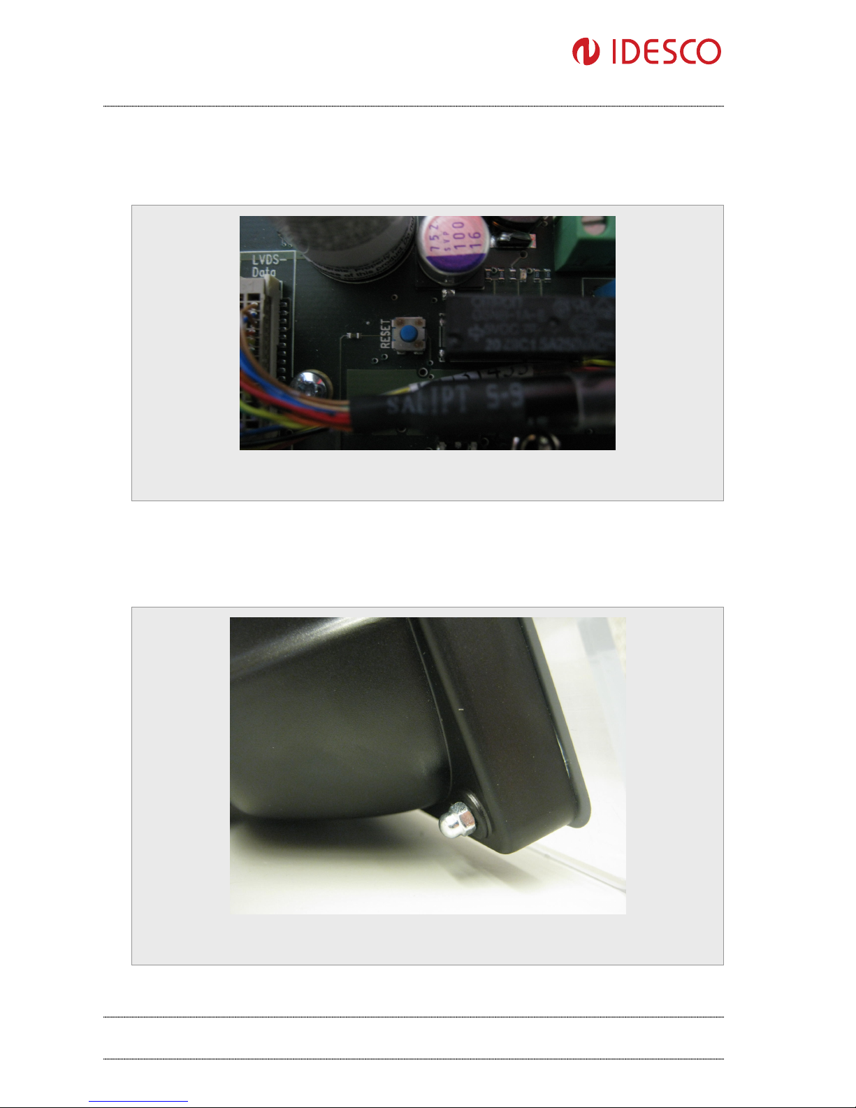
5.2.8. Reset button
Access Touch 2.0 has one reset button that can be used to shutdown the device without any shutdown procedures. Reset button can be used to force a shutdown.
Picture 7:Reset button
5.3. Mounting
After all connections have been completed, mount the front cover with the assembly plate to the back
cover and lock it in place with four nuts in the corners (picture 7).
Picture 8:Front cover and assembly plate installation to the back cover

R&D
Access Touch 2.0 – User Manual
Version 1.03
Public 10 (12)
Author: Hal File: C00320E Date: 18.8.2012
Approved: Jpo Printed: 20.08.2012 09:45
Idesco Oy | Teknologiantie 9, FIN-90590 OULU | Tel +358 20 743 4175 | info@idesco.fi | www.idesco.fi
5.4. Booting
After all mechanical and electronic installations have been completed switch the power supply on.
The computer will automatically initiate its boot routine.
Note that the power-up routine may differ depending upon whatever features may have been
configured in the device. The device will initiate booting of the installed operating system if no such
configurations have been made.
After the power-up routine completes your Access Touch 2.0 is ready for use.
6. System shutdown
Do not suddenly remove power from the device!
On Linux device use shell command “halt.” After halt procedure is finished (screen is black and device is not drawing any current) you can unplug your power source from the device.
On Windows device select shutdown from Start menu.
7. Dimensions
7.1. Front panel
Picture 9: Front panel measures in millimetres

R&D
Access Touch 2.0 – User Manual
Version 1.03
Public 11 (12)
Author: Hal File: C00320E Date: 18.8.2012
Approved: Jpo Printed: 20.08.2012 09:45
Idesco Oy | Teknologiantie 9, FIN-90590 OULU | Tel +358 20 743 4175 | info@idesco.fi | www.idesco.fi
7.2. Side measures
Picture 10 : Side measures in millimetres
8. Technical data
Operating frequency for RFID / Wireless RFID 125 KHz and 13,56 MHz. Wireless
ommunication 2,4 GHz
Power supply 14 ... 30 VDC.
Internal back
- up
capacitors for safe power down
CPU
Intel® Atom™ Z510 1.1 GHz.
Note
: Access
Touch 2.0 COM module is alterable to fit customer requirements. Contact Idesco Oy if
you need
default module to be changed
.
Current consumption 520 mA @ 24 VDC (when display on)
Memory 1GB internal flash memory for Linux OS
512 MB DDR2 on the module
Separate SSD memory can be used for
Windows OS installation. SSD must be
ordered separately, not provided by default
Display and Touch Panel 8,4’’ display and 5-wire resistive touch panel
Dimensions of housing 330 x 200 x 100 mm
Material of housing Plastic
Installation method Screws

R&D
Access Touch 2.0 – User Manual
Version 1.03
Public 12 (12)
Author: Hal File: C00320E Date: 18.8.2012
Approved: Jpo Printed: 20.08.2012 09:45
Idesco Oy | Teknologiantie 9, FIN-90590 OULU | Tel +358 20 743 4175 | info@idesco.fi | www.idesco.fi
Protection class IP20
Operational temperature range -0 ... +50 °C
Storage temperature range -10 ... +50 °C
Interfaces
RS232, Wiegand, Ethernet, RS485, Wireless
(RF), USB (device)
Inputs
2 general purpose inputs
Outputs Two software controlled outputs (open collector)
Two software controlled relays
EMC Emitted interference: EN 61000-6-4: 2001
Interference resistant: EN 61000-6-2: 2001
LED (for the RFID reader) Red / Yellow LED.
Ethernet 10 / 100 Mbit LAN
Wireless communication Optional WLAN or Idesco Cardea (IEEE
802.15.4)”
 Loading...