

Idesco 7C 2.0, 8CD 2.0, 7AH C Installation Instructions Manual
R&D
7C 2.0 / 8CD 2.0 C – Installation Instructions
Version 1.01
Public 1 (2)
Author: Hha File: C00716E Date: 02.08.2016
Approved: Kyl
Idesco Oy | Teknologiantie 9, FIN-90590 OULU | Tel +358 20 743 4175 | info@idesco.fi | www.idesco.fi
Installation Instructions
7C 2.0 / 8CD 2.0 / 7AH C
Idesco Oy vakuuttaa, että 7C 2.0 / 8CD 2.0 / 7AH C lukija on direktiivien 2014/30/EU (EMC), 2014/35/EU
(Low voltage directive), 2011/65/EU (RoHS) ja
2014/53/EU (RED) oleellisten vaatimusten ja sitä
koskevien direktiivien muiden ehtojen mukainen.
7C 2.0 / 8CD 2.0 / 7AH C reader herewith complies
with the requirements of the EMC Directive 2014/30/EU, the Low Voltage Directive 2014/35/EU, the RoHS Directive 2011/65/EU,
the RED Directive 2014/53/EU and carries the CE
marking accordingly.
Tehonsyöttö:
10...30 VDC 150 mA
Liitin 1:
10...30VDC ...………..... Pin 1
GND ……..…………….. Pin 2
WIE0 / (Data) ………..… Pin 3
WIE1 / (Clock).…........... Pin 4
TxD ...………….............. Pin 5
RxD............…………..… Pin 6
Vihreä LED.................... Pin 7
Punainen LED / DWNL. Pin 8
Liitin 2:
Summeri........................ Pin 1
NC...................…............ Pin 2
NC................................... Pin 3
NC......................... Pin 4
NC.......................... Pin 5
In 1................................. Pin 6
Out 1......….................... Pin 7
Out 2...........………….… Pin 8
Lukijoiden sijoittaminen alle 10 cm etäisyydelle
toisistaan tai lukijan asentaminen metallipinnalle
saattaa lyhentää lukuetäisyyttä.
Älä asenna voimakkaiden sähköhäiriölähteiden
läheisyyteen.
Mikäli punaisen LEDin ohjaus on lukijaa
käynnistettäessä kytkettynä maahan, lukija odottaa 10
sekuntia ohjelmistopäivitystä. Mikäli
ohjelmistopäivitystä ei käynnistetä, lukija jatkaa
toimintaansa normaalisti.
Ulostulon maksimi virrankesto on 500mA
Jos optinen tamper –kytkin on konfiguroitu käyttöön,
huomaattehan että asennuspaikan pintamateriaali voi
vaikuttaa kytkimen toimintaetäisyyteen.
Power supply:
10...30 VDC 150 mA
Connector 1:
10...30VDC ..…………..... Pin 1
GND ……..…………….. Pin 2
WIE0 / (Data) ………..… Pin 3
WIE1 / (Clock).….......... Pin 4
TxD……………...……… Pin 5
RxD…………………..… Pin 6
Green LED.........……… Pin 7
Red LED / DWNL….….. Pin 8
Connector 2:
Speaker......................... Pin 1
NC.................................. Pin 2
NC.....................….…..… Pin 3
NC…………............ Pin 4
NC……….….…..… Pin 5
In 1..........…................... Pin 6
Out 1..................…........ Pin 7
Out 2..............………..… Pin 8
If readers are placed closer than 10 cm away from
each other or if the reader is installed on metal the
reading distance can be shorter.
Do not install close to sources of powerful electromagnetic disturbance.
In case the red LED input is connected to GND while
the reader is switched on, the reader will wait for SW
update for 10 seconds. If the SW update is not started, the reader continues to function normally.
Output maximum current is 500mA
If optical tamper switch is configured in use, please
note that installation place’s surface material can
effect to tamper switch operating distance.
R&D
7C 2.0 / 8CD 2.0 C – Installation Instructions
Version 1.01
Public 2 (2)
Author: Hha File: C00716E Date: 02.08.2016
Approved: Kyl
Idesco Oy | Teknologiantie 9, FIN-90590 OULU | Tel +358 20 743 4175 | info@idesco.fi | www.idesco.fi
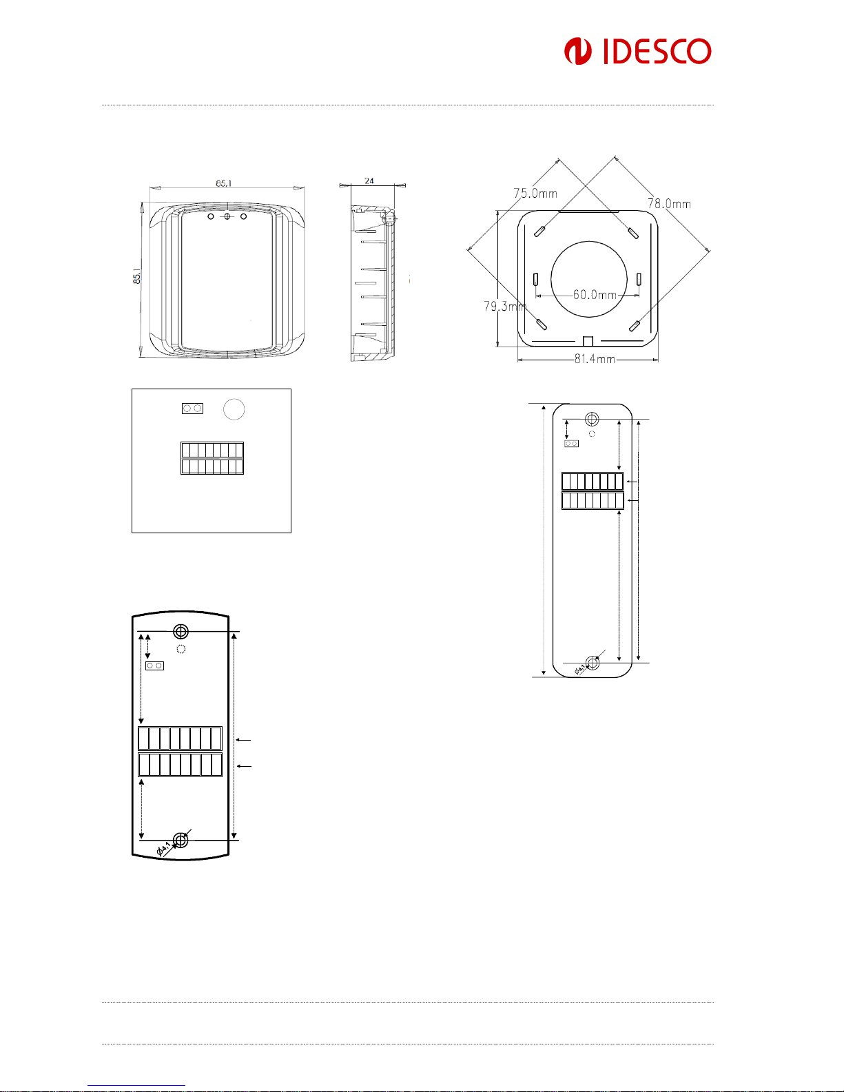
1 2 3 4 5 6 7 8
8 7 6 5 4 3 2 1
Connector 1
Connector 2
120
140
All dimensions
in millimeters
Led
Tamper
10
35
68
Quattro housing
1 2 3 4 5 6 7 8
8 7 6 543
2 1
BUZZER
CONNECTOR 1
CONNECTOR 2
TAMPER
Slim housing
1 2 3 4 5 6 7 8
8 7 6 5 4 3 2 1
Connector 1
Connector 2
Note, connector 1 and 2 installation
hole depth should be at least 5 mm
94
Led
All dimensions
in millimeters
40
Tamper
15
36
Basic housing
 Loading...