

Page 1
Device command description & firmware update procedure
Dagobertstrasse 9
D - 55116 Mainz
Germany
Phone +49 (0) 61 31-30476-0
Fax +49 (0) 61 31-30 476-20
Email. info@arygon.com
http://www.arygon.com
UHF Desktop Reader / Module - AUxx series
Page 2
ARYGON TECHNOLOGIES AG
A p p l i c a t i o n N o t e
AUxx UHF reader AN © All rights reserved. Copyright by Arygon Technologies AG - 2011 Page 2 of 28
Revision
Date
Description
1.0
01.03.2011
Initial version
1.1
07.04.2011
Added Error code Information and state charts, command frame review with
firmware
1.2
27.05.2011
Channel selection and switching (frequency hopping) description added
Document: Application Note
Author: ARYGON Technologies AG
Version: 1.2
Document History
Table 1 - Dokument History
Contact Information
For additional information and sales office addresses visit:
http://www.arygon.com or http://www.nfc-global.com
Page 3

ARYGON TECHNOLOGIES AG
A p p l i c a t i o n N o t e
AUxx UHF reader AN © All rights reserved. Copyright by Arygon Technologies AG - 2011 Page 3 of 28
FCC NOTICE
Note: This equipment has been tested and found to comply with the limits for a Class B digital
device, pursuant to part 15 of the FCC Rules. These limits are designed to provide reasonable
protection against harmful interference in a residential installation. This equipment generates,
uses and can radiate radio frequency energy and, if not installed and used in accordance with the
instructions, may cause harmful interference to radio communication. However, there is no
guarantee that interference will not occur in a particular installation. If this equipment does cause
harmful interference to radio or television reception, which can be determined by turning the
equipment off
and on, the user is encouraged to try to correct the interference by one or more of the following
measures:
Reorient or relocate the receiving antenna
Increase the separation between the equipment and receiver
Connect the equipment into an outlet on a circuit different from that to which the receiver
is connected
Consult the dealer or an experienced radio/TV technician for help
THIS DEVICE COMPLIES WITH PART 15 OF FCC RULES. OPERATION IS SUBJECT TO THE FOLLOWING
WO CONDITIONS:
1) THIS DEVICE MAY NOT CAUSE HARMFUL INTERFERENCE AND
2) THIS DEVICE MUST ACCEPT ANY INTERFERENCE RECEIVED, INCLUDING INTERFERENCE
THAT MAY CAUSE UNDESIRED OPERATION
WARNING: CHANGES OR MODIFICATIONS NOT EXPRESSLY APPROVED BY THE PARTY RESPONSIBLE
FOR COMPLIANCE COULD VOID THE USER’S AUTHORITY TO OPERATE THE
1. Disclaimer
Products sold by ARYGON Technologies AG are covered by the ARYGONSs Term and Conditions of Sale.
ARYGON Technologies AG makes no warranty, express, statutory, implied, or by description regarding the
information set forth herein or regarding the freedom of the described devices from patent infringement.
ARYGON Technologies AG reserves the right to change specifications and prices at any time and without notice.
Therefore, please check with ARYGON Technologies AG for current information.
This product is intended for use in normal commercial applications. Applications requiring extended
temperature range, unusual environmental requirements, or high reliability applications, such as for military,
medical life-support or life-sustaining equipment are specifically not recommended without additional
consultation of ARYGON Technologies AG.
The information provided in this document by ARYGON Technologies AG is believed to be correct and accurate.
However, ARYGON Technologies AG shall not be liable to recipient or any third party for any damages,
including but not limited to personal injury, property damage, loss of profits, loss of use, interruption of
business or indirect, special, incidental or consequential damages, of any kind, in connection with or arising out
of the furnishing, performance or use of the technical data herein. No obligation or liability to recipient or any
third party shall arise or flow out of ARYGON Technologies AG rendering of technical or other services.
Page 4

ARYGON TECHNOLOGIES AG
A p p l i c a t i o n N o t e
AUxx UHF reader AN © All rights reserved. Copyright by Arygon Technologies AG - 2011 Page 4 of 28
Table of Contents:
1. Disclaimer ........................................................................................................... 3
2. Introduction ........................................................................................................ 7
Application Layer ................................................................................................................. 7
USB Report-Frame................................................................................................................. 7
USB Reports.......................................................................................................................... 7
Reader Related USB Reports ................................ ................................................................ .. 8
callSendFirmwareHardwareID .................................................................................................................... 8
callAntennaPower ....................................................................................................................................... 8
writeRegister ............................................................................................................................................... 9
callReadRegister .......................................................................................................................................... 9
callReadRegisters ........................................................................................................................................ 9
callChangeFreq .......................................................................................................................................... 10
configGen2 ................................................................................................................................................ 12
callEnableBootloader ................................................................................................................................ 13
callStartStop .............................................................................................................................................. 13
Tag Related USB Reports ......................................................................................................14
callInventory.............................................................................................................................................. 14
callInventoryRSSIInternal .......................................................................................................................... 14
callInventory6B ......................................................................................................................................... 15
callSelectTag .............................................................................................................................................. 15
callWriteToTag .......................................................................................................................................... 16
writeToTag6B ............................................................................................................................................ 17
callReadFromTag ....................................................................................................................................... 17
readFromTag6B ......................................................................................................................................... 17
callLockUnlock ........................................................................................................................................... 18
callKillTag ................................................................................................................................................... 18
callNXPCommands .................................................................................................................................... 19
Error Byte ............................................................................................................................20
Protocol Layer - Gen2 ..........................................................................................................21
Protocol Layer - ISO6B ................................................................ .........................................25
Device Specific Functions .....................................................................................................26
Firmware functionality regarding frequency hopping .............................................................26
3. Firmware update of the ADRU reader ................................................................. 28
Page 5

ARYGON TECHNOLOGIES AG
A p p l i c a t i o n N o t e
AUxx UHF reader AN © All rights reserved. Copyright by Arygon Technologies AG - 2011 Page 5 of 28
List of Tables:
Table 1 - Dokument History ....................................................................................................... 2
Table 2 Report Frame .............................................................................................................. 7
Table 3 USB Reports Overview .................................................................................................. 7
Table 4- callSendFirmwareHardwareID - outgoing ....................................................................... 8
Table 5- callSendFirmwareHardwareID - incoming ....................................................................... 8
Table 6 –callAntennaPower - outgoing ....................................................................................... 8
Table 7 - callAntennaPower - incoming ....................................................................................... 8
Table 8 - writeRegister – outgoing ............................................................................................. 9
Table 9 - writeRegister – incoming ............................................................................................. 9
Table 10 - callReadRegister - outgoing ........................................................................................ 9
Table 11 - callReadRegister - incoming ....................................................................................... 9
Table 12 - callReadRegisters - outgoing ...................................................................................... 9
Table 13 - callReadRegisters - incoming ...................................................................................... 9
Table 14 - callChangeFreq - Get RSSI Level - outgoing ..................................................................10
Table 15 - callChangeFreq - Get RSSI Level - incoming .................................................................10
Table 16 - callChangeFreq - Get Reflected Power Level - outgoing ................................................10
Table 17 - callChangeFreq - Get Reflected Power Level - incoming ................................................10
Table 18 - callChangeFreq – Add frequency to hopping list - outgoing ...........................................10
Table 19 - callChangeFreq – Add frequency to hopping list - incoming ..........................................10
Table 20 –Clear frequency hopping list - outgoing.......................................................................10
Table 21 - Clear frequency hopping list – incoming .....................................................................10
Table 22 – Set frequency hopping parameters - outgoing ............................................................11
Table 23 - Set frequency hopping parameters - incoming ............................................................11
Table 24 - Get frequency hopping parameters – outgoing ............................................................11
Table 25 - Get frequency hopping parameters – incoming ...........................................................11
Table 26 - Continuous modulation test – outgoing ......................................................................11
Table 27 - Continuous modulation test – incoming .....................................................................11
Table 28 – configGen2 - outgoing .............................................................................................12
Table 29 – configGen2 - incoming ................................ ............................................................. 12
Table 30 - configGen2 - parameter settings ................................................................................12
Table 31 - callEnableBootloader – outgoing ...............................................................................13
Table 32 - callEnableBootloader – incoming ...............................................................................13
Table 33 - callStartStop - outgoing ............................................................................................13
Table 34 - callStartStop - incoming ............................................................................................13
Table 35 - callInventory - outgoing ............................................................................................14
Table 36 - callInventory - incoming ...........................................................................................14
Table 37 - callInventoryRSSIInternal - outgoing ...........................................................................14
Table 38 - callInventoryRSSIInternal – incoming..........................................................................14
Table 39 - callInventory6B – outgoing ........................................................................................15
Table 40 - callInventory6B – incoming .......................................................................................15
Table 41 - callSelectTag - outgoing ............................................................................................16
Table 42 - callSelectTag - incoming ............................................................................................16
Table 43 - callWriteToTag - outgoing .........................................................................................16
Table 44 - callWriteToTag – incoming ........................................................................................16
Table 45 - writeToTag6B - outgoing ...........................................................................................17
Table 46 - writeToTag6B – incoming ..........................................................................................17
Table 47 - callReadFromTag - outgoing ......................................................................................17
Table 48 - callReadFromTag - incoming .....................................................................................17
Table 49 - readFromTag6B - outgoing ........................................................................................17
Table 50 - readFromTag6B - outgoing ........................................................................................17
Table 51 - callLockUnlock - outgoing .........................................................................................18
Page 6

ARYGON TECHNOLOGIES AG
A p p l i c a t i o n N o t e
AUxx UHF reader AN © All rights reserved. Copyright by Arygon Technologies AG - 2011 Page 6 of 28
Table 52 - callLockUnlock - incoming .........................................................................................18
Table 53 - callKillTag - outgoing ................................................................................................18
Table 54 - callKillTag - incoming ................................................................................................18
Table 55 - callNXPCommands - EAS command - outgoing ............................................................19
Table 56 - callNXPCommands - Set / Reset Protect - outgoing ......................................................19
Table 57 - callNXPCommands - Calibrate - outgoing ....................................................................19
Table 58 - callNXPCommands - Change Config - outgoing ............................................................19
Table 59 - callNXPCommands - incoming ...................................................................................19
Table 60 - Error Byte ...............................................................................................................20
Table 61 - Gen2 Functions ........................................................................................................21
Table 62 - AS399x_public Functions ..........................................................................................25
Table 63 - AS399x - Functions ...................................................................................................26
List of Figures:
Picture 1 - Gen2 Tag Singulation ...............................................................................................15
Picture 2 - Gen2 - State Diagram ................................ ............................................................... 22
Picture 3 - Gen2 - State Diagram (no password set).....................................................................22
Picture 4 - Gen2 Anti Collision – State Diagram ...........................................................................24
Picture 5 - ISO6B - State Diagram ..............................................................................................25
Picture 6 - Parameters .............................................................................................................25
Picture 7 - Firmeware updating response ...................................................................................28
Page 7
ARYGON TECHNOLOGIES AG
A p p l i c a t i o n N o t e
AUxx UHF reader AN © All rights reserved. Copyright by Arygon Technologies AG - 2011 Page 7 of 28
2. Introduction
Byte 1
Byte 2
Variable length
Report ID
Frame Length
Payload
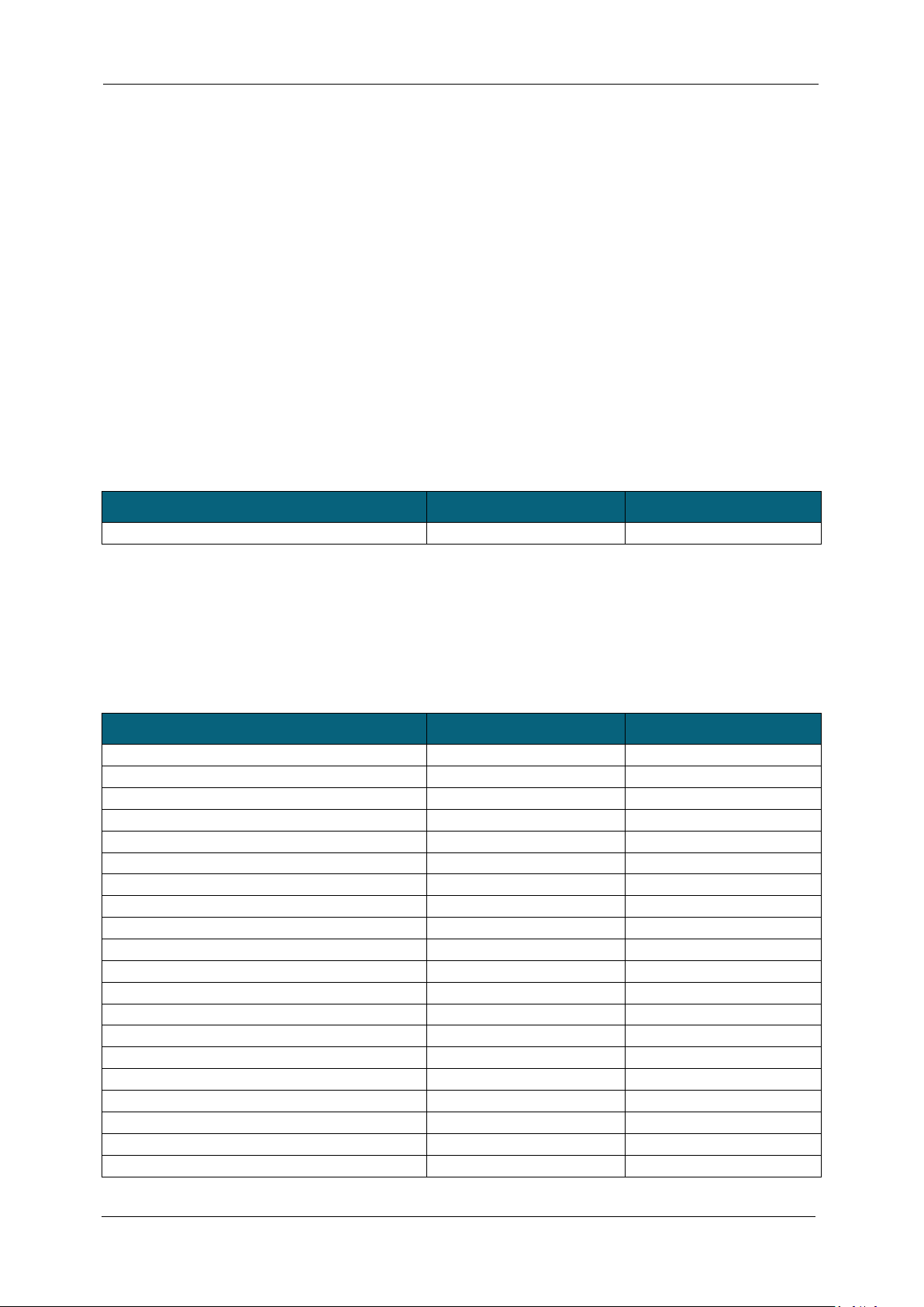
USB Report Name
Report ID outgoing
Report ID incoming
callSendFirmwareHardwareID
0x10
0x11
callAntennaPower
0x18
0x19
writeRegister
0x1A
0x1B
callReadRegister
0x1C
0x1D
callReadRegisters
0x57
0x58
callChangeFreq
0x41
0x42
configGen2
0x59
0x5A
callEnableBootloader
0x55
0x56
callStartStop
0x5D
0x5E
callInventory
0x31
0x32
callInventoryRSSIInternal
0x43
0x44
callInventory6B
0x3F
0x40
callSelectTag
0x33
0x34
callWriteToTag
0x35
0x36
writeToTag6B
0x47
0x48
callReadFromTag
0x37
0x38
readFromTag6B
0x49
0x50
callLockUnlock
0x3B
0x3c
callKillTag
0x3D
0x3E
callNXPCommands
0x45
0x46
This document describes the architecture important functions. For a complete reference of implemented
functions please refer to the Doxygen documentation.
Application Layer
After connecting the reader to the computer the reader is automatically installed as a HID (Human Interface
Device). The USB HID protocol defines different reports. Every report starts with its own report ID defining the
length and if it is an incoming or an outgoing report.
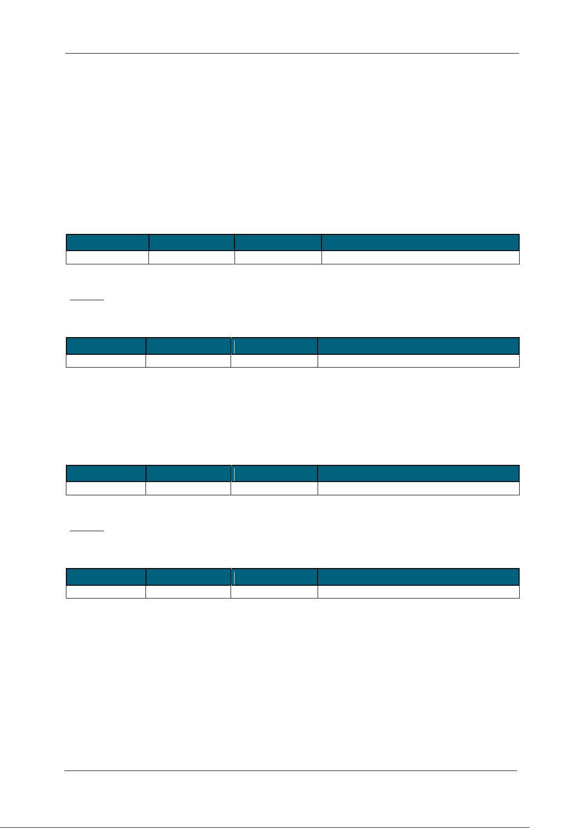
USB Report-Frame
Each report frame starts with a Report ID byte. The second byte defines the length of the frame (the ID and the
length bytes are included in the length).
Table 2 Report Frame
USB Reports
The following table gives an overview of the implemented USB reports. Each USB report causes the device to
reply with a response frame (incoming report).
Table 3 USB Reports Overview
Page 8
ARYGON TECHNOLOGIES AG
A p p l i c a t i o n N o t e
AUxx UHF reader AN © All rights reserved. Copyright by Arygon Technologies AG - 2011 Page 8 of 28
It is recommended to send the reports always with the maximal report length of 64 bytes. Most reports are
Byte 0 1
2
Content
0x10(ID)
3(length)
Payload
Byte 0 1
2 .. 47
Content
0x11(ID)
length
Zero terminated string
Byte 0 1
2
Content
0x18(ID)
3(length)
Payload
Byte 0 1
2
Content
0x19(ID)
3(length)
0 on success
already defined in the descriptor with the maximal length. The others may change in future. Windows
truncates longer reports and discards shorter reports!
Reader Related USB Reports
These commands are intended to configure the AUDR UHF reader and for obtaining information about the
firmware.
callSendFirmwareHardwareID
This report sends the firmware or the hardware ID to the host computer.
Table 4- callSendFirmwareHardwareID - outgoing
Payload:
0x00…Firmware
0x01…Hardware
Table 5- callSendFirmwareHardwareID - incoming
callAntennaPower
This report enables or disables the RF power on the RF-output ports.
Table 6 –callAntennaPower - outgoing
Payload:
0x00…RF-Power OFF
0x01…RF-Power ON
Table 7 - callAntennaPower - incoming
Page 9
ARYGON TECHNOLOGIES AG
A p p l i c a t i o n N o t e
AUxx UHF reader AN © All rights reserved. Copyright by Arygon Technologies AG - 2011 Page 9 of 28
writeRegister
Byte 0 1 2 3 4 5
Content
0x1A(ID)
5(length)
reg_number
val_0
val_1
val_2
Byte 0 1
2
Content
0x1B(ID)
3(length)
0 on success
Byte 0 1
2
Content
0x1C(ID)
2(length)
reg_number
Byte 0 1 2 3 4 5
Content
0x1D(ID)
6(length)
0x00 on success
val0
val1
val2
Byte 0 1
Content
0x57(ID)
1(length)
Byte 0 1 2 …
44
Content
0x58(ID)
45(length)
reg 0x00
…
reg 0x1F
This function writes one register of the AUDR UHF reader.
Table 8 - writeRegister – outgoing
val_1 and val_2 are used only if reg_number is a deep register (e.g.: Modulator Control Register).
If reg_number ≥ 0x80 a direct command is executed.
Table 9 - writeRegister – incoming
callReadRegister
This function reads one register from the AUDR UHF reader
Table 10 - callReadRegister - outgoing
If a 3-bytes deep register is selected the controller sends back 3 data bytes.
Table 11 - callReadRegister - incoming
callReadRegisters
This function reads all register in one bulk from AUDR UHF reader.
Table 12 - callReadRegisters - outgoing
Table 13 - callReadRegisters - incoming
Page 10

ARYGON TECHNOLOGIES AG
A p p l i c a t i o n N o t e
AUxx UHF reader AN © All rights reserved. Copyright by Arygon Technologies AG - 2011 Page 10 of 28
callChangeFreq
Byte 0 1 2 3 .. 5
Content
0x41(ID)
length
0x01
freq
Byte 0 1 2 3
Content
0x42(ID)
64(length)
I-channel
Q-channel
Byte 0 1 2 3 .. 5
Content
0x41(ID)
length
0x02
freq
Byte 0 1 2 3
Content
0x42(ID)
64(length)
I-channel
Q-channel
Byte 0 1 2 3 .. 5
6
7
Content
0x41(ID)
length
0x04
freq
rssi_threshhold(dBm)
profile_id
Byte 0 1 2 3
Content
0x42(ID)
64(length)
0xFC on success
0xFF on success
Byte 0 1
2
Content
0x41(ID)
length
0x08
Byte 0 1 2 3
Content
0x42(ID)
64(length)
0xFC on success
0xFF on success
This report sets, modifies or measures frequency related properties. freq comprises 3 bytes and is transmitted
in kHz. E.g.: 868000 means 868 MHz.
Get RSSI Level
Table 14 - callChangeFreq - Get RSSI Level - outgoing
Table 15 - callChangeFreq - Get RSSI Level - incoming
Get Reflected Power Level
Table 16 - callChangeFreq - Get Reflected Power Level - outgoing
Table 17 - callChangeFreq - Get Reflected Power Level - incoming
Add frequency to frequency list used for hopping
Table 18 - callChangeFreq – Add frequency to hopping list - outgoing
Table 19 - callChangeFreq – Add frequency to hopping list - incoming
Clear frequency list used for hopping
Table 20 –Clear frequency hopping list - outgoing
Table 21 - Clear frequency hopping list – incoming
Page 11

ARYGON TECHNOLOGIES AG
A p p l i c a t i o n N o t e
AUxx UHF reader AN © All rights reserved. Copyright by Arygon Technologies AG - 2011 Page 11 of 28
Set frequency hopping related parameters
Byte 0 1 2 3 .. 4
5 .. 6
7 .. 8
Content
0x41(ID)
length
0x10
listeningTime
maxSendingTime
idleTime
Byte 0 1 2 3
Content
0x42(ID)
64(length)
0xFC on success
0xFF on success
Byte 0 1
2
Content
0x41(ID)
length
0x11
Byte 0 1
2 3 4
5 .. 6
7 .. 8
Content
0x42(ID)
64(length)
0xfe
0xff
profile_id
listening_time
max_sending_time
9 .. 10
11 .. 13
14 .. 16
17
18
19
idle_time
gui_min_freq
gui_max_freq
gui_num_freqs
rssi_threshold
act_num_freqs
Byte 0 1 2 3 .. 5
6 .. 7
Content
0x41(ID)
length
32
don't care
duration in ms
Byte 0 1 2 3
Content
0x42(ID)
64(length)
0xfe
0xff
Table 22 – Set frequency hopping parameters - outgoing
Table 23 - Set frequency hopping parameters - incoming
Get frequency hopping related parameters
Table 24 - Get frequency hopping parameters – outgoing
Table 25 - Get frequency hopping parameters – incoming
Continuous modulation test
Starts continuous modulation of the RF field for given duration. If duration is set to 0 continuous modulation is
active until the next report is received from GUI.
Table 26 - Continuous modulation test – outgoing
Table 27 - Continuous modulation test – incoming
Page 12

ARYGON TECHNOLOGIES AG
A p p l i c a t i o n N o t e
AUxx UHF reader AN © All rights reserved. Copyright by Arygon Technologies AG - 2011 Page 12 of 28
configGen2
Byte
0 1 2 3 4 5 6
7
Content
0x59(ID)
length
set_lf
lf
set_coding
coding
set_session
session
8 9 10
11
12
13
set_trext
trext
set_qbegin
qbegin
set_sensitivity
sensitivity
Byte 0 1
2 3 4 5 6
7
Content
0x5A(ID)
0x40(length)
reserved(0)
lf
reserved(0)
coding
reserved(0)
session
8 9 10
11
12
13
reserved(0)
trext
reserved(0)
qbegin
reserved(0)
sensitivity
Name
values
lf
0 = 40 kHz,
3 = 80 kHz (not available for AS3992),
6 = 160 kHz,
8 = 213 kHz,
9 = 256 kHz,
12 = 320 kHz,
15 = 640 kHz
coding
0 = FM0,
1 = Miller2,
2 = Miller4,
3 = Miller8
session
0 = S0,
1 = S1,
2 = S2,
3 = SL
trext
0 = short preamble, pilot tone,
1 = long preamble, pilot tone
qbegin
0 .. 15. Initial gen2 round is 2^qbegin long
sensitivity
-128 .. 127 (dBm)
This function sets and reads various gen2 related settings. The values are only being set if the proper set_ value
is set to 1.
Table 28 – configGen2 - outgoing
Table 29 – configGen2 - incoming
Values for the different parameters are:
Table 30 - configGen2 - parameter settings
Page 13

ARYGON TECHNOLOGIES AG
A p p l i c a t i o n N o t e
AUxx UHF reader AN © All rights reserved. Copyright by Arygon Technologies AG - 2011 Page 13 of 28
callEnableBootloader
Byte 0 1 2 3
Content
0x55(ID)
4(length)
dont_care
dont_care
Byte 0 1
2
Content
0x56(ID)
3(length)
1 on success
Byte 0 1 2 3
Content
0x5D(ID)
6(length)
update
start
Byte 0 1
2
Content
0x5E(ID)
3(length)
current start value
Subsequently callInventoryRSSIInternal() result packages are returned in a
dense continuous loop. See there for description.
This function erases the programmed firmware but does not affect the bootloader. The firmware of the device
needs to be reprogrammed afterwards.
Table 31 - callEnableBootloader – outgoing
Table 32 - callEnableBootloader – incoming
callStartStop
This function starts/stops the automatic scanning procedure.
Table 33 - callStartStop - outgoing
Table 34 - callStartStop - incoming
Page 14

ARYGON TECHNOLOGIES AG
A p p l i c a t i o n N o t e
AUxx UHF reader AN © All rights reserved. Copyright by Arygon Technologies AG - 2011 Page 14 of 28
Tag Related USB Reports
Byte 0 1
2
Content
0x31(ID)
3(length)
start
Byte 0 1 2 3
4 5 6 .. 6 + epclen
Content
0x32(ID)
length
tags_left
epclen+pclen
pc[0]
pc[1]
epc
Byte 0 1
2
Content
0x43(ID)
3(length)
start
Byte 0 1 2 3
4 .. 6
7
Content
0x44(ID)
length
tags_left
RSSI_value
base_freq
epclen+pclen
8 9 10 .. 10 + epclen
pc[0]
pc[1]
epc
Transponder related USB reports force the microcontroller and the AUDR UHF reader to communicate with
UHF RFID tags. The RF- power at the antenna needs to be enabled and at least one tag should be in the RF-field
coverage of the reader.
callInventory
This function performs a gen2 protocol inventory round according to parameters given by configGen2().
Table 35 - callInventory - outgoing
start: 1 -> start a new round, 2 -> deliver next tag
The device reports back all tags in a burst mode.
Table 36 - callInventory - incoming
With byte 2 the controller reports how many tags are found by the inventory command. After issuing the first
inventory report and with start-byte = 2 the controller reports back the count of tags not inventoried yet. This
information is used to inform the host how often he has to call the inventory command in order to inventory all
available tags. The tag information is kept in the microcontroller's tag list. No tag information is deleted.
callInventoryRSSIInternal
This function performs a gen2 protocol inventory round according to parameters given by configGen2().
Table 37 - callInventoryRSSIInternal - outgoing
start: 1 -> start a new round
start: 2 -> deliver next tag
The device reports back all tags in a burst mode.
Table 38 - callInventoryRSSIInternal – incoming
RSSI_value: upper 4 bits I channel, lower 4 bits Q channel
base_freq: base frequency at which the tag was found.
With byte 2 the controller reports how many tags are found by the inventory command. After issuing the first
inventory report and with start-byte = 2 the controller reports back the count of tags not inventoried yet. This
Page 15

ARYGON TECHNOLOGIES AG
A p p l i c a t i o n N o t e
AUxx UHF reader AN © All rights reserved. Copyright by Arygon Technologies AG - 2011 Page 15 of 28
information is used to inform the host how often he has to call the inventory command in order to inventory all
Byte 0 1 2 3
4 .. 11
12
Content
0x3F(ID)
12(length)
start
mask
word_data
start_address
Byte 0 1 2 3
4
5 .. 12
13 .. 15
Content
0x40(ID)
13(length)
tags_left
rssi(planned)
8(epclen)
uid
used freq
Command Inventory
Pick one Tag out of
the population found
Individual commands
to Tag like read or
write
Command Select or
Isolate Tag
available tags. The tag information is kept in the microcontroller's tag list. No tag information is deleted.
callInventory6B
This function performs one inventory round using ISO18000-6b protocol. Reading or writing to the tag will not
succeed without sending this report first.
Table 39 - callInventory6B – outgoing
start: 1 -> start a new round
start: 2 -> deliver next tag
mask: Mask value for GROUP_SELECT_EQ command, 0 will select all tags
start_address: address where data comparision will be started
word_data: data which will be compared
Table 40 - callInventory6B – incoming
With byte 2 the controller reports how many tags are found by the inventory command. After issuing the first
inventory report and with start-byte = 2 the controller reports back the count of tags not inventoried yet. This
information is used to inform the host how often he has to call the inventory command in order to inventory all
available tags. The tag information is kept in the microcontroller's tag list. No tag information is deleted.
callSelectTag
Prior to communicate with one tag the host must isolate one of the found tags. The host needs to send always
all EPC bytes to the controller regardless how long the EPC mask is specified. The complete report length is 64
bytes and needs to be taken into account by the host
The correct sequence to operate that command is shown below:
Picture 1 - Gen2 Tag Singulation
Page 16

ARYGON TECHNOLOGIES AG
A p p l i c a t i o n N o t e
AUxx UHF reader AN © All rights reserved. Copyright by Arygon Technologies AG - 2011 Page 16 of 28
This function singulates a Gen2 tag using the given mask for subsequent operations like read/write
Byte 0 1 2 3 .. 3 + mask_length
Content
0x33(ID)
length
mask_length
mask
Byte 0 1
2
Content
0x34(ID)
3(length)
status (Error Byte)
Byte 0 1 2 3
4 .. 7 8 9 .. 9 + 2 * data_len
Content
0x35(ID)
length
mem_type
address
acces_pw
data_len
data
Byte 0 1
2
3
Content
0x36(ID)
3(length)
status (Error Byte)
num_words_written
Table 41 - callSelectTag - outgoing
Table 42 - callSelectTag - incoming
callWriteToTag
This function writes to a previously selected Gen2 tag.
Table 43 - callWriteToTag - outgoing
access_pw: if access password is non-zero the tag will be accessed first
mem_type:
o 0:reserved membank
o 1:EPC membank
o 2:TID membank
o 3:USER membank
data_len: data length in 16-bit words
Table 44 - callWriteToTag – incoming
Page 17

ARYGON TECHNOLOGIES AG
A p p l i c a t i o n N o t e
AUxx UHF reader AN © All rights reserved. Copyright by Arygon Technologies AG - 2011 Page 17 of 28
writeToTag6B
Byte 0 1
2 .. 9
10
11
12 .. 12+length_to_write
Content
0x47(ID)
length
uid
addr
length_to_write
data
Byte 0 1
2
Content
0x48(ID)
3(length)
0 for success
Byte 0 1 2 3
4
Content
0x37(ID)
length
mem_type
address
data_len
Byte 0 1
2
3
Content
0x38(ID)
length
Status (Error Byte)
num_words_read
Byte 0 1
2 .. 9
10
11
Content
0x49(ID)
12(length)
uid
addr
length_to_read
Byte 0 1 2 3
4 .. 4+length_to_read
Content
0x50(ID)
64(length)
0 for success
length of data
data
This function writes data to a tag using ISO18000-6b protocol command WRITE.
Table 45 - writeToTag6B - outgoing
Table 46 - writeToTag6B – incoming
callReadFromTag
This function reads from a previously selected gen2 tag.
Table 47 - callReadFromTag - outgoing
mem_type:
o 0:reserved membank
o 1:EPC membank
o 2:TID membank
o 3:USER membank
data_len: data length to read in 16-bit words
Table 48 - callReadFromTag - incoming
readFromTag6B
This function reads from a tag using ISO18000-6b protocol command READ_VARIABLE.
Table 49 - readFromTag6B - outgoing
Table 50 - readFromTag6B - outgoing
Page 18

ARYGON TECHNOLOGIES AG
A p p l i c a t i o n N o t e
AUxx UHF reader AN © All rights reserved. Copyright by Arygon Technologies AG - 2011 Page 18 of 28
callLockUnlock
Byte 0 1 2 3
4 .. 7
Content
0x3B(ID)
8(length)
lock_unlock
memory_space
access password
Byte 0 1
2
Content
0x3C(ID)
3(length)
Status (Error Byte)
Byte 0 1
2 .. 5
6
Content
0x3D(ID)
7(length)
kill password
recom
Byte 0 1
2
Content
0x3E(ID)
3(length)
Status (Error Byte)
This report locks a gen2 tag.
lock_unlock:
0 Unlock
1 Lock
2 Permalock
3 Lock & Permalock
memory_space:
0 Kill password
1 Access password
2 EPC
3 TID
Table 51 - callLockUnlock - outgoing
Table 52 - callLockUnlock - incoming
callKillTag
This function kills a gen2 tag.
Table 53 - callKillTag - outgoing
recom: see GEN2 standard: table on "XPC_W1 LSBs and a Tag's recomissioned status"
Table 54 - callKillTag - incoming
Page 19

ARYGON TECHNOLOGIES AG
A p p l i c a t i o n N o t e
AUxx UHF reader AN © All rights reserved. Copyright by Arygon Technologies AG - 2011 Page 19 of 28
callNXPCommands
Byte 0 1 2 3
4 .. 7
Content
0x45(ID)
10(length)
1
eas_on
access pw
Byte 0 1 2 3
4 .. 7
Content
0x45(ID)
10(length)
2
set_protect
access pw
Byte 0 1 2 3
4 .. 7
Content
0x45(ID)
10(length)
8
not_used
access pw
Byte 0 1 2 3
4 .. 7
8..9
Content
0x45(ID)
10(length)
9
not_used
access pw
config
Byte 0 1
2
3 .. 4
Content
0x46(ID)
5(length)
Status (Error Byte)
config word (only change config)
This function sends special NXP command to NXP gen2 tags.
EAS command
Table 55 - callNXPCommands - EAS command - outgoing
Set / Reset Protect
Table 56 - callNXPCommands - Set / Reset Protect - outgoing
Calibrate
Table 57 - callNXPCommands - Calibrate - outgoing
Change Config
Table 58 - callNXPCommands - Change Config - outgoing
To all NXP related the report the device responds:
Table 59 - callNXPCommands - incoming
Page 20

ARYGON TECHNOLOGIES AG
A p p l i c a t i o n N o t e
AUxx UHF reader AN © All rights reserved. Copyright by Arygon Technologies AG - 2011 Page 20 of 28
Error Byte
Value
Error-Code Name
Description
0x00
GEN2_OK
No Error
0x01
GEN2_ERR_REQRN
Error sending ReqRN.
0x02
GEN2_ERR_ACCESS
Error sending Access password.
0x03
GEN2_ERR_KILL
Error sending Kill.
0x04
GEN2_ERR_NOREPLY
Error no reply received.
0x05
GEN2_ERR_LOCK
Error locking command.
0x06
GEN2_ERR_BLOCKWRITE
Error Blockwrite.
0x07
GEN2_ERR_BLOCKERASE
Error Blockerase.
0x08
GEN2_ERR_READ
Error Reading.
0x09
GEN2_ERR_SELECT
Error when selecting tag.
0x0A
GEN2_ERR_CHANNEL_TIMEOUT
Error RF channel timed out.
0x80
Other Error
Catch-all for errors not covered by other codes.
0x83
Memory Overrun
The specified memory location does not exist or the EPC
length field is supported by the Tag
0x84
Memory locked
The specified memory location is locked and/or
permalocked and is either nor writeable or not readable.
0x8B
Insufficient power
The Tag has insufficient power to perform the memory –
write operation.
0x8F
Non-specific error
The Tag does not support error-specific codes
0xFF
No response from the Tag (time out)
Some report frames which are sent from the controller to the host computer include an error byte:
Table 60: Error Byte
Page 21

ARYGON TECHNOLOGIES AG
A p p l i c a t i o n N o t e
AUxx UHF reader AN © All rights reserved. Copyright by Arygon Technologies AG - 2011 Page 21 of 28
Protocol Layer - Gen2
Data Type
Function
unsigned
gen2SearchForTags (Tag *tags, u8 maxtags, u8 *mask, u8 length, u8 q, bool(*cbContinueScanning)(void),
bool useMaskToSelect)
unsigned
gen2SearchForTagsFast (Tag *tags_, u8 maxtags, u8 *mask, u8 length, u8 q,
bool(*cbContinueScanning)(void))
u8
gen2AccessTag (Tag *tag, u8 *password)
u8
gen2LockTag (Tag *tag, u8 *mask_action)
u8
gen2KillTag (Tag *tag, u8 *password, u8 rfu)
u8
gen2WriteWordToTag (Tag *tag, u8 memBank, u8 wordPtr, u8 *databuf)
u8
gen2NXPChangeConfig (Tag *tag, u8 *databuf)
u8
gen2ReadFromTag (Tag *tag, u8 memBank, u8 wordPtr, u8 wordCount, u8 *destbuf)
u8
gen2SetProtectBit (Tag *tag)
u8
gen2ReSetProtectBit (Tag *tag, u8 *password)
u8
gen2ChangeEAS (Tag *tag, u8 value)
u8
gen2Calibrate (Tag *tag)
void
gen2PrintTagInfo (Tag *tag, u8 epclen, u8 tagNr)
void
gen2Configure (const struct gen2Config *config)
void
gen2Open (const struct gen2Config *config)
void
gen2Close (void)
Table 61 - Gen2 Functions
Page 22

ARYGON TECHNOLOGIES AG
A p p l i c a t i o n N o t e
AUxx UHF reader AN © All rights reserved. Copyright by Arygon Technologies AG - 2011 Page 22 of 28
Before calling any of the functions the AUDR UHF reader chip needs to be
initialized using AUDR UHF readerInitialize().
Next the function gen2Open() needs to be called for opening a session.
gen2SearchForTags() should be called to identify the tags in reach. Typically tag
singulation is done next.
In order to do so gen2SearchForTags() is called again provided a proper mask to
singulate (select) a tag.
In this case only one tag is returned by gen2SearchForTags().
This tag is then in the Open/Secured state and may be accessed using the other
Gen2 functions (gen2WriteWordToTag(), gen2ReadFromTag(), ...).
When finished with gen2 operations this session should be closed using
gen2Close().
State Diagram:
Picture 2 - Gen2 - State Diagram
State Diagram – Tag has no password set:
Picture 3 - Gen2 - State Diagram (no password set)
Page 23

ARYGON TECHNOLOGIES AG
A p p l i c a t i o n N o t e
AUxx UHF reader AN © All rights reserved. Copyright by Arygon Technologies AG - 2011 Page 23 of 28
Typical Use-Case:
Tag tags[16];
struct gen2Config config = {GEN2_LF_160, GEN2_COD_MILLER2, GEN2_IINV_S0, 1};
unsigned n;
u8 buf[4];
...
readerInitialize(912000);
gen2Open(&config);
n = gen2SearchForTags(tags,16,0,0,4);
if ( n == 0) return;
//Pick one of the tags based on the contents of tags. Here we use the very first tag
if (gen2ReadFromTag(tags+0, MEM_USER, 0, 2, buf))
return;
buf[0] ^= 0xff; buf[1]^= 0x55; // change the data
if (gen2WriteWordToTag( tags+0, MEM_USER, 0, buf))
{ // wrote back one of the two read words
gen2Close();
return;
}
//...
gen2Close();
Page 24

ARYGON TECHNOLOGIES AG
A p p l i c a t i o n N o t e
AUxx UHF reader AN © All rights reserved. Copyright by Arygon Technologies AG - 2011 Page 24 of 28
One of the more complex flowcharts is the Inventory algorithm in which the 6c anti-collision
Start
Wait for Tx
complete
Send select
Wait for Rx
response
TX complete Interrupt
Send query or
query rep
No RX Interrupt
Wait for Tx
complete
Wait for
response
TX complete Interrupt
Check slots
No Rx Interrupt
Slots left
Provide
Inventory List
no slots left
Send ACK
Rx Interrupt
Wait for Tx
Complete
Wait for
response
Get EPC from FIFO
request handle
Rx Interrupt
Tx complete IRQ
No Rx Interrupt
Wait for Tx
Complete
Wait for
response
Read Handle
Rx Interrupt
Tx complete IRQ
No Rx Interrupt
Restart slots
is executed.
Picture 4: Gen2 Anti Collision – State Diagram
Page 25

ARYGON TECHNOLOGIES AG
A p p l i c a t i o n N o t e
AUxx UHF reader AN © All rights reserved. Copyright by Arygon Technologies AG - 2011 Page 25 of 28
Protocol Layer - ISO6B
Data Type
Function
u16
as399xInitialize (u32 baseFreq)
unsigned char
as399xReadChipVersion (void)
void
as399xSwitchToIdleMode (void)
void
as399xSelectLinkFrequency (u8 a)
void
as399xSetBaseFrequency (u8 regs, u32 frequency)
void
as399xMemoryDump (void)
void
as399xAntennaPower (u8 on)
void
as399xGetRSSI (u16 num_of_ms_to_scan, u8 *rawIQ, s8 *dBm)
void
as399xSaveSensitivity ()
void
as399xRestoreSensitivity ()
s8
as399xSetSensitivity (s8 minimumSignal)
s8
as399xGetSensitivity (void)
u16
as399xGetReflectedPower (void)
void
as399xReset (void)
Before calling any of the functions herein the AUDR UHF READER needs to be initialized
using AS339xreaderInitialize(). Thereafter the function iso6bOpen() needs to be called for
opening a session.
The following graph shows several states of an ISO 6B tag as well as their transitions based
on iso6b* commands:
Protocol Layer - AS399x_public
Picture 5 - ISO6B - State Diagram
Table 62 - AS399x_public Functions
Page 26

ARYGON TECHNOLOGIES AG
A p p l i c a t i o n N o t e
AUxx UHF reader AN © All rights reserved. Copyright by Arygon Technologies AG - 2011 Page 26 of 28
Device Specific Functions
Data Type
Function
void
as399xSingleCommand (u8 command)
void
as399xContinuousRead (u8 address, s8 len, u8 *readbuf)
void
as399xFifoRead (s8 len, u8 *readbuf)
u8
as399xSingleRead (u8 address) reentrant
void
as399xWritePredistortion (const u8 *buf)
void
as399xContinuousWrite (u8 address, u8 *buf, s8 len)
void
as399xSingleWrite (u8 address, u8 value)
void
as399xCommandContinuousAddress (u8 *command, u8 com_len, u8 address, u8 *buf, u8
buf_len)
u8
as399xGetFIFOStatus (void)
u8
as399xGetIRQStatus (void)
void
as399xWaitForResponse (u16 waitMask)
void
as399xWaitForResponseTimed (u16 waitMask, u16 ms)
void
as399xEnterDirectMode ()
void
as399xExitDirectMode ()
Table 63 - AS399x - Functions
Subject to change without notice
Implementation of frequency hopping
The device is designed for worldwide use. Per default it loads the European frequency setup upon start up.
Different setup can be applying the commands described in tables 18 – 25. Nevertheless the default function
implemented in firmware after loading the region specific frequencies is as follows.
ARYGON Reader Suite GUI is designed to allow most freedom in select different adoptions in the worldwide
setup.
Picture 6 – Parameters
Page 27

ARYGON TECHNOLOGIES AG
A p p l i c a t i o n N o t e
AUxx UHF reader AN © All rights reserved. Copyright by Arygon Technologies AG - 2011 Page 27 of 28
In the frequency section e.g. USA settings:
Each setting can also be manually changed upon user requirements.
The selection of a profile will load region specific settings for:
Start frequency: The lowest channel frequency
End frequency: the highest channel frequency
Increment: The channel spacing between two channels
RSSSI Threshold: give the opportunity to set a Listen before Talk (LBT) value. In case a LBT is not
needed or not wanted, this level should be as high as possible ( e.g. -40 dB) The thresholds that can
be managed by the system starts at -47 dBm and can reach up to -86 dBm. (Please note that the
levels are chip values and can be changed by the external components. That means that Arygon will
have a 10 dB higher value than the described value in the GUI)
Listen time: This time specify how long the reader is listening to the channel. The largest recorded
signal during the listen time will determine the channel power.
Idle time: This time specify the time between two channel hop.
Maximum allocation time: This time define the maximum time on one frequency.
The profile will be transferred with the “Set” Button to the reader.
After press the button, the GUI will start to transfer a randomized frequency table List and store it in its
memory. Now the reader will change the frequency on every Inventory or Tag command according to the list.
Since the Gen2 anti collision round is limited by the slot counter Q, it is possible to calculate the maximum
allocated channel time to less than 400ms. Nevertheless it is also possible to limit the channel allocation time
with the maximum allocation time. Since Arygon is used as a desktop reader, the user is advised to use a max
Q value of less than 4.
The Gen2 settings are for individual Link frequencies.
For USA, it is recommended
Link frequency: 256 kHz
Session:S0
Q_Begin: 4
Page 28

ARYGON TECHNOLOGIES AG
A p p l i c a t i o n N o t e
AUxx UHF reader AN © All rights reserved. Copyright by Arygon Technologies AG - 2011 Page 28 of 28
3. Firmware update of the AUxx reader
Assuming that the boot loader is already loaded into the flash memory the firmware of the AUxx reader system
can be updated in an easy way. Care needs to be taken that the ARYGON Reader Suite is not running at the
same time during the programming process. To program the AUxx UHF reader system simply double click the
batch file “FWupdate_ARYGON_UHF_reader.bat”. The batch file will run the “up.exe” executable which loads
the “Arygon.bin” into the micro AUDR‘s flash memory. Therefore those two files need to be present in the
same directory as the batch file itself.
When the programming is completed the message “Successfully written xxxx bytes” appears. Hit any key to
close the window and return to WINDOWS.
Picture 7: Firmware updating response
The Arygon readers are now able to communicate with the ARYGON Reader Suite via USB.
In case of problems, please contact: info@arygon.com . http://www.arygon.com
 Loading...