

Page 1

User_Manual - Multi-ISO_HF_Reader - USB_Ver1.6.doc- Confidential
Muullttii--IISS
M
UUsseerr M
O HHFF RReeaaddeerr –– UUSSBB
O
Maannuuaall
Erthalstrasse 1
Version: 1.6 Page 1 of 48
D - 55118 Mainz
Germany
Phone +49 (0) 61 31-30476-0
Fax +49 (0) 61 31-30 47 6-20
info@arygon.com • http://www.arygon.com
Page 2

Page 3

User_Manual - Multi-ISO_HF_Reader - USB_Ver1.6.doc- Confidential
CONTENTS
1
GETTING STARTED...................................................................................................................................5
1.1 DRIVER INSTALLATION ................................................................................................ ...........................5
1.2 TROUBLE SHOOTING DRIVER INSTALLATION.........................................................................................8
2 DIAGNOSTICS......................................................................................................... .....................................9
2.1 DRIVER VERSION DETECTION............................................................................... ..................................9
2.2 FIRMWARE VERSION DETECTION.......... ................................................................................................11
3 CARD READER SUITE – TEST APPLICATION ........................... ... .... ... .. ... .... ... .. ..... .. .. ..... .. ... .... ... .. ..13
3.1 FIRMWARE DOWNLOAD ........................................................................................................................13
3.2 PCSC DIAGNOSTICS ...............................................................................................................................13
3.3 BINARY CONFIGURATION ......................................................................................................................14
4 PCSC 2.0...................................................... .. .. ..... .. ... .... ... .. ... .... ... .. ..... .. .. ... .... ... .. ..... .. ............................... ....15
4.1 HOW TO ACCESS CONTACTLESS CARDS VIA PCSC?......................................... ...................................15
4.1.1 Establish Context............................................. ............................. ............................ .......................15
4.1.2 List Readers ..................................... ................................................................................................15
4.1.3 Connect ................................................................................................................... .........................16
4.1.4 Data and Command transfer with Card..........................................................................................16
4.1.5 Disconnect........................................................................................................................................16
4.1.6 Release.............................................................................................................................................16
4.2 ATR GENERATION ................................................................................................................................17
4.2.1 CPU Cards.......................................................................................................................................17
4.2.2 Storage Cards ..................................................................................................................................17
5 ACCESSING READER THROUGH PCSC.............................. ..... .. .. ... .... ... .. ..... .. .. ... ..... .. .. ..... .. ... .. ..... .. ..18
5.1 READER CONTROL COMMANDS............................................................................................................18
5.1.1 Get Static RF Parameters.......................... .... ... .. .. ..... .. ... .. ..... .. .. ... .... ... .. .. ..... ... .. .. ..... .. ... .. ..... ...........18
5.1.2 Set Static RF Parameters......................................... .. .. ... .. ..... .. .. ... .... ... .. ... .... ... .. .. ... .... ... .. .. ..............19
5.1.3 Get Dynamic RF Parameters ..........................................................................................................19
5.1.4 Set Dynamic RF Parameters ........................................................ ...................................................19
5.1.5 RF Parameters Data Structure........................... ...................................................... .......................20
5.2 KEY MANAGEMENT ............................................................... ...............................................................23
5.2.1 Reader Authentication.............. ........................................................ ............................. ..................23
5.2.2 Load Keys................................................................................. ........................................................24
6 ACCESSING CARDS THROUGH PCSC.............................................................................................. ..26
6.1 MIFARE CARDS......................................................... .............................................................................26
6.1.1 Authenticate ............................ .........................................................................................................26
6.1.2 Write Binary............................................ ... .. .. ..... .. ... .. ..... .. .. ... .... ... .. .. ..... .. ... .. ..... .. ... .. .......................27
6.1.3 Read Binary ..................................... .. ..... ... .. .. ..... .. ... .. ..... .. .. ... .... ... .. .. ..... .. ... .. ..... .. ... .. ..... ..................27
6.1.4 Value Increment............................. .. .. ..... .. ... .. ... .... ... .. .. ..... .. ... .. ..... .. .. ... .. ..... .. ... .. ..... .. .. ... .. ................27
6.1.5 Value Decrement.............................. .. ... .. ..... .. ... .... ... .. .. ..... .. ... .. ..... .. .. ... .... ... .. .. ..... ... .. ..... .. ................28
6.2 ISO 15693 CARDS ................. ................................................................................................................29
6.2.1 Read Single Block................................................. ... .... ... .. .. ..... .. ... .. ..... .. ... .. .. ..... .. ... .. ..... .. ................29
6.2.2 Write Single Block .................................. ... .. ..... .. .. ... .. ..... .. .. ... .... ... .. .. ..... ... .. .. ... .... ... .. .. ..... .. ..............29
6.2.3 Lock Block...................................... .... ... .. .. ..... .. ... .. ..... .. ... .. ..... .. .. ... .... ... .. .. ... .... ... .. ... .... .....................29
6.2.4 Read Multiple Blocks.......................... .... ... .. .. ..... .. ... .. .. ..... .. ... .. .. ..... .. ... .. ... .... ... .. .. ..... .. ... .. .. ..............30
6.2.5 Write AFI .............................................. .. .. ..... ... .. .. ..... .. ... .. ..... .. .. ... .... ... .. ..... .. .. ... ..... .. .. .....................31
6.2.6 Write DSFID.................................................. ... .. .. ..... .. ... .... ... .. .. ..... .. ... .. ..... .. ... .. ..... .. .. ..... ................31
6.2.7 Get System Information:................................... .. .. ..... .. ... .. .. ..... .. ... .. ..... .. .. ... .. ..... .. .. ... ..... .. .. ... ...........31
6.2.8 Get Multiple Block Security Status:................................................................................................32
6.3 CRYPTO RF CARDS ...............................................................................................................................33
6.3.1 Set User Zone.............................. ... .. .. ..... .. ... .. ..... .. ... .. ..... .. .. ... .... ... .. .. ..... .. ... .. ..... .. ... .. ..... ..................33
6.3.2 Read User Zone ........................................ ... .. ... .. ..... .. .. ... .... ... .. .. ..... .. ... .. .. ..... ... .. .. ..... .. ... .. .. ..............33
Version: 1.6 Page 3 of 48
Page 4

User_Manual - Multi-ISO_HF_Reader - USB_Ver1.6.doc- Confidential
6.3.3 Write User Zone.......................... ... .... ... .. .. ..... ... .. ..... .. .. ... .... ... .. .. ..... .. ... .. ..... .. ... .... ... .. .. ..... ................33
6.3.4 Read System Zone............................................. .. .. ..... .. ... .. .. ..... .. ... .. ..... .. ... .. .. ..... .. ... .. ..... .. .. ..... .........34
6.3.5 Write System Zone ..................................... .. .. ..... .. ... .. ..... .. .. ... .... ... .. .. ..... ... .. .. ... .... ... .. .. ..... .. ..............34
6.3.6 Check Password.................................... ....................................................................................... ....34
6.4 DESFIRE CARDS .......................... .........................................................................................................35
6.5 GENERIC APDUS ..................................... .............................................................................................35
6.5.1 Get UID............................ .. .. ..... .. ... ..... .. .. ..... .. ... .. ..... .. .. ..... .. ... .... ... .. ..... .. ... .. ..... .. .. ..... .. ... ..................35
6.5.2 Traverse .................................... ..................................................................................... ..................35
6.6 STATUS WORD ......................................................................................................................................37
7 APDU SAMPLES TO ACCESS CARDS............ .......................................................... ............................38
7.1 HOW TO ACCESS MIFARE CLASSIC CARDS? ........................................................................................38
7.2 HOW TO ACCESS MIFARE UL CARDS? ............................ ....................................................................39
7.3 HOW TO ACCESS DESFIRE CARDS? .....................................................................................................40
7.3.1 DESFIRE EV1 Specific commands:...................................... ............................ ............................ ..43
7.4 HOW TO ACCESS ISO15693 CARDS? ............................. ........................................................................44
7.5 HOW TO ACCESS CRYPTO RF CARDS?.................................................. .................................................45
7.6 HOW TO ACCESS ICODE-SLI CARDS?..................................................................................................46
APPENDIX A TERMS AND ABBREVIATIONS.....................................................................................47
APPENDIX B REFERENCES........................................ .............................................................................48
Version: 1.6 Page 4 of 48
Page 5
User_Manual - Multi-ISO_HF_Reader - USB_Ver1.6.doc- Confidential
1 Getting Started
The Multi-IS O HF USB Reader /Writer i s a Desktop co ntactles s smart card/ tag reader an d writer
for accessing MIFARE, ISO14443-4 TypeA, ISO14443-4 TypeB, Mifare DESFire, Mifare DESFire EV1,
NFC tags and ISO 15693 tags. This document is intended for application developers who want to
access contactless cards using the Multi-ISO HF USB Reader/Writer.
Following sections explain how to install drivers for the Multi-ISO HF USB Reader/Writer in
Windows operating system (illustrations are taken from Windows XP, same being applicable for other
Windows versions).
1.1 Driver Installation
Drivers are necessary to access Multi-ISO HF USB Reader/Writer. The following steps illustrate
the installation procedure.
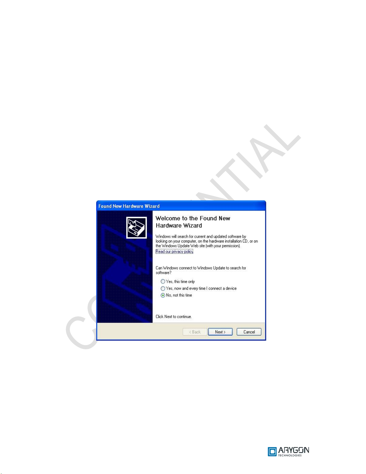
1. Plug in the reader in USB port
2. “Found New Hardware Wizard” will appear. Select “No, not this time” and c lick “Next” to
continue driver installation.
Version: 1.6 Page 5 of 48
Page 6
User_Manual - Multi-ISO_HF_Reader - USB_Ver1.6.doc- Confidential
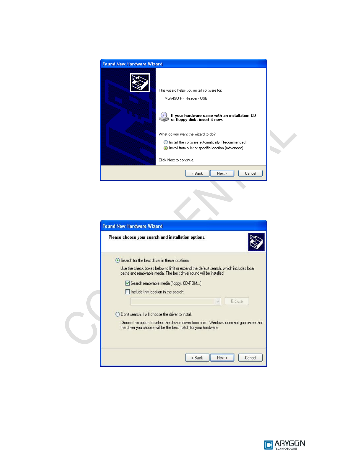
3. In the next appearing dialog box, select “Install from a list or specific location (Advanced)”
and click on “ Next”
4. In next dialog box select “Search for the best driver in these locations” and “Search
removable media (floppy, CD-ROM…)” sub option. Insert the installation CD that is given
along with the reader kit and click “Next”.
Version: 1.6 Page 6 of 48
Page 7
User_Manual - Multi-ISO_HF_Reader - USB_Ver1.6.doc- Confidential
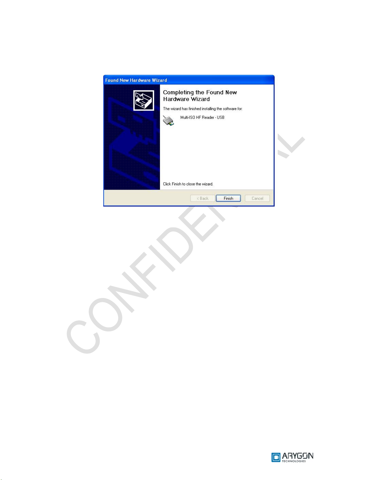
5. Wait until the driver installation is completed by the operating system and the installation
success dialog is displayed as shown below. Click “Finish”. Now the drivers are installed
successfully.
Version: 1.6 Page 7 of 48
Page 8
User_Manual - Multi-ISO_HF_Reader - USB_Ver1.6.doc- Confidential
1.2 Trouble Shooting Driver Installation
Device will not function properly if wrong driver is installed or if there is a version incompatibility
between the firmware and driver. In these cases, the installed driver must be uninstalled and proper
driver must be installed as explained below
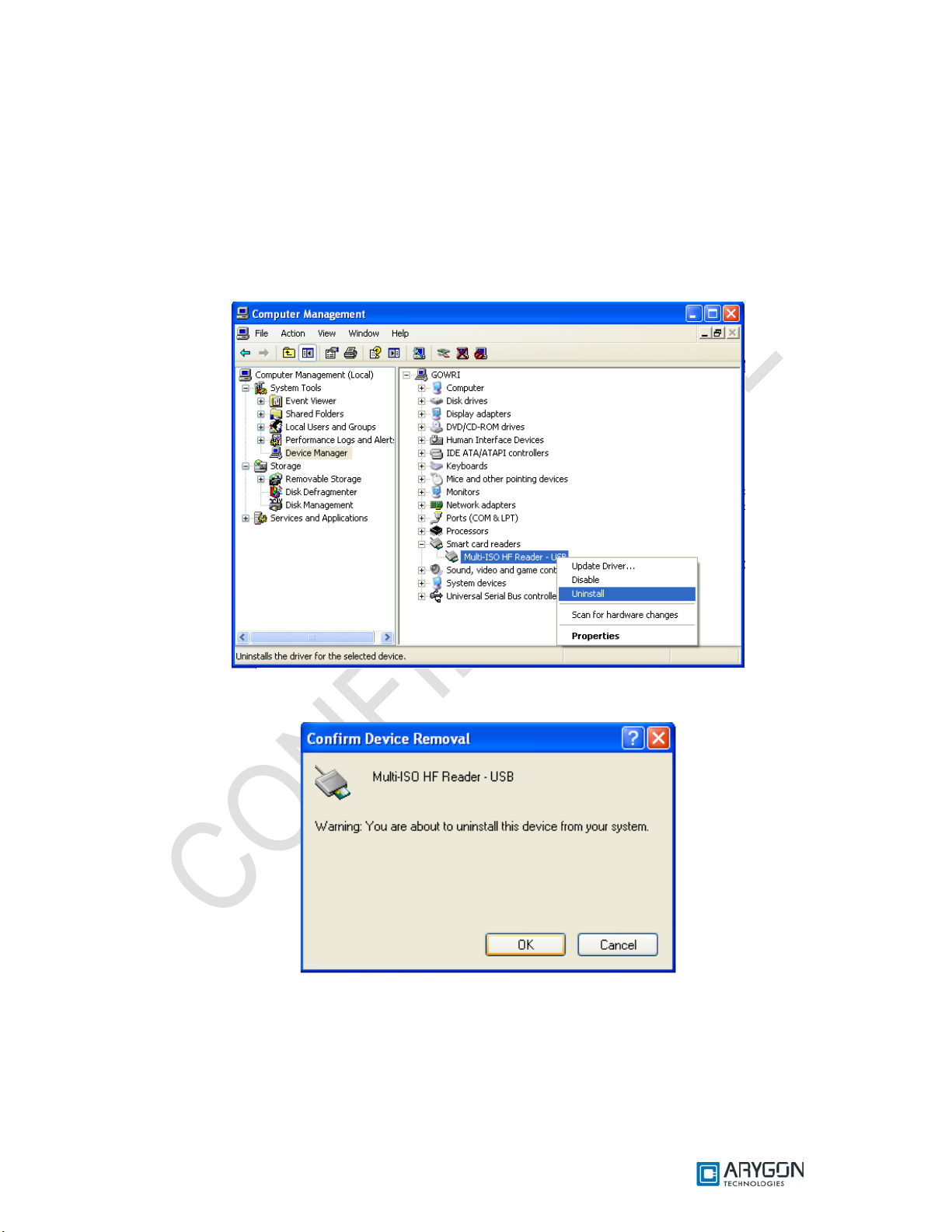
Un-installation procedure is as follows.
1. Open the device manager -> Smart card readers and select “Multi-ISO HF Reader – USB”
2. Right click on “Multi-ISO HF Reader – USB” and select “Uninstall”
3. In the following dialog click “OK”.
4. The device will now disappear from the device manager
5. Un-plug and re-plug the device
6. System will prompt for drivers. Install the drivers as described in the driver installation
procedure section 1.1.
Version: 1.6 Page 8 of 48
Page 9
User_Manual - Multi-ISO_HF_Reader - USB_Ver1.6.doc- Confidential
2 Diagnostics
Version of the driver and firmware plays an important role in the proper working of the device.
Device may malfunction if incompatible drivers are installed for particular version of firmware. The
compatibility of the driver and firmware can be found in the “Document history” section of this
document.
2.1 Driver Version Detection
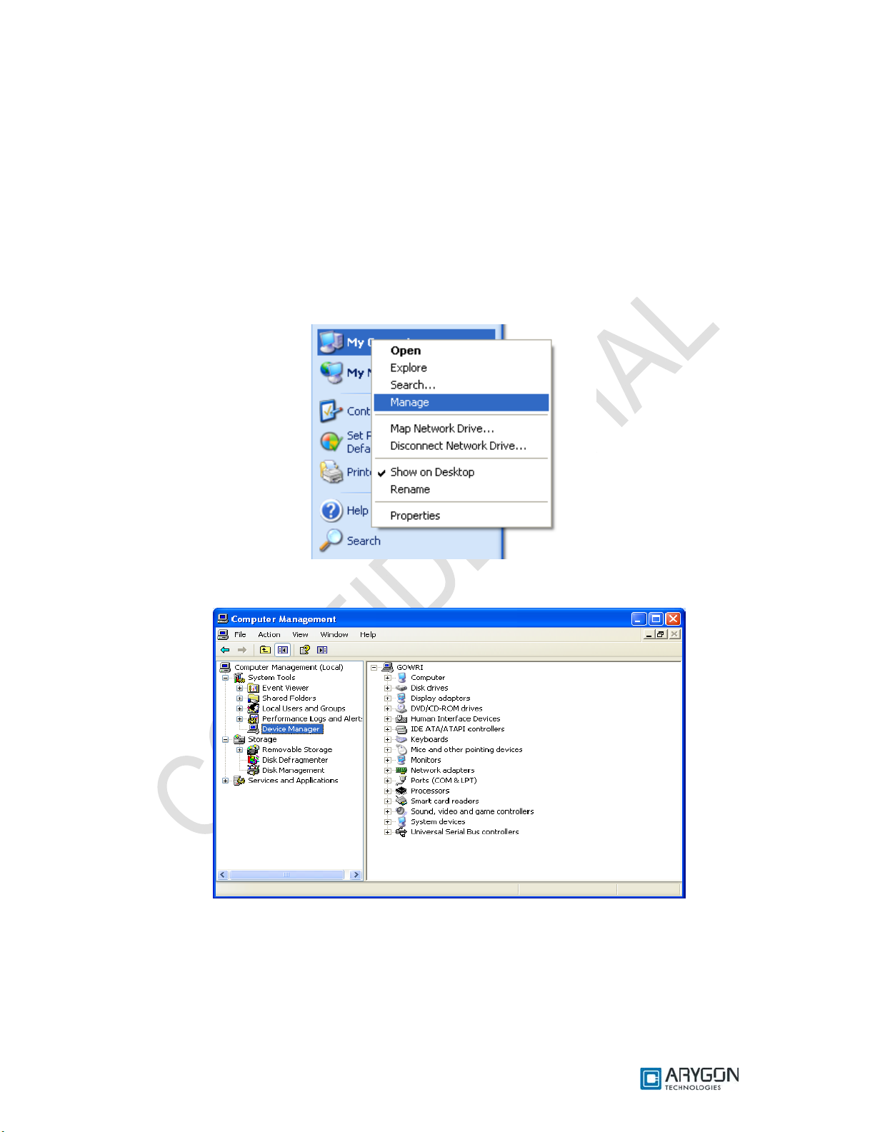
Driver version detectio n is described in the foll owing proce dure.
1. Right click on the “My Computer” icon and click on “Manage”
2. In following dialog, select “Device Manager” under “System Tools” menu in the left pane.
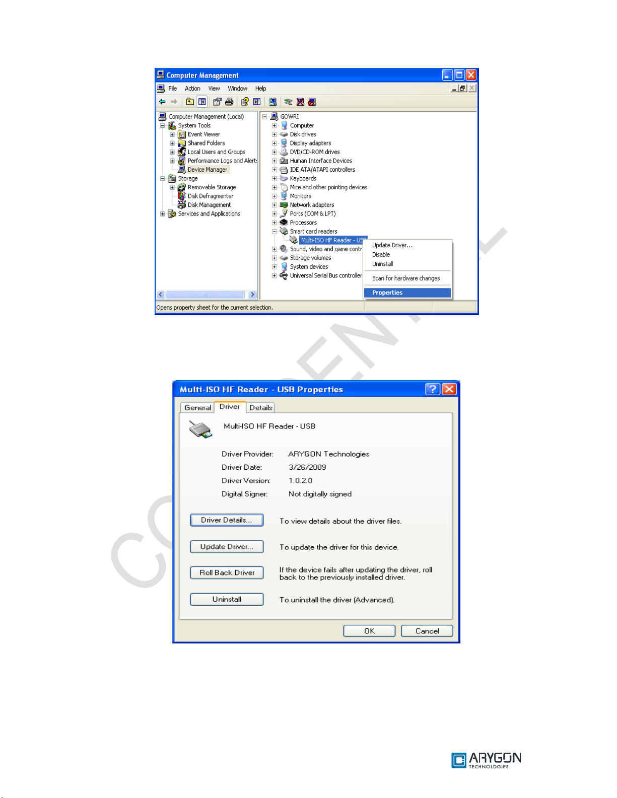
3. Double click on “Smart card readers ” in the right pane. Right click on “Multi-ISO HF Reader
- USB”, and select “Properties”.
Version: 1.6 Page 9 of 48
Page 10
User_Manual - Multi-ISO_HF_Reader - USB_Ver1.6.doc- Confidential
4. In the dialog box which appears, select the “Driver” tab, driver version can be found in the tab
window. For example, the driver version will appear as
“Driver Version: 1.0.2.0” for driver version 1.02
Version: 1.6 Page 10 of 48
Page 11
User_Manual - Multi-ISO_HF_Reader - USB_Ver1.6.doc- Confidential
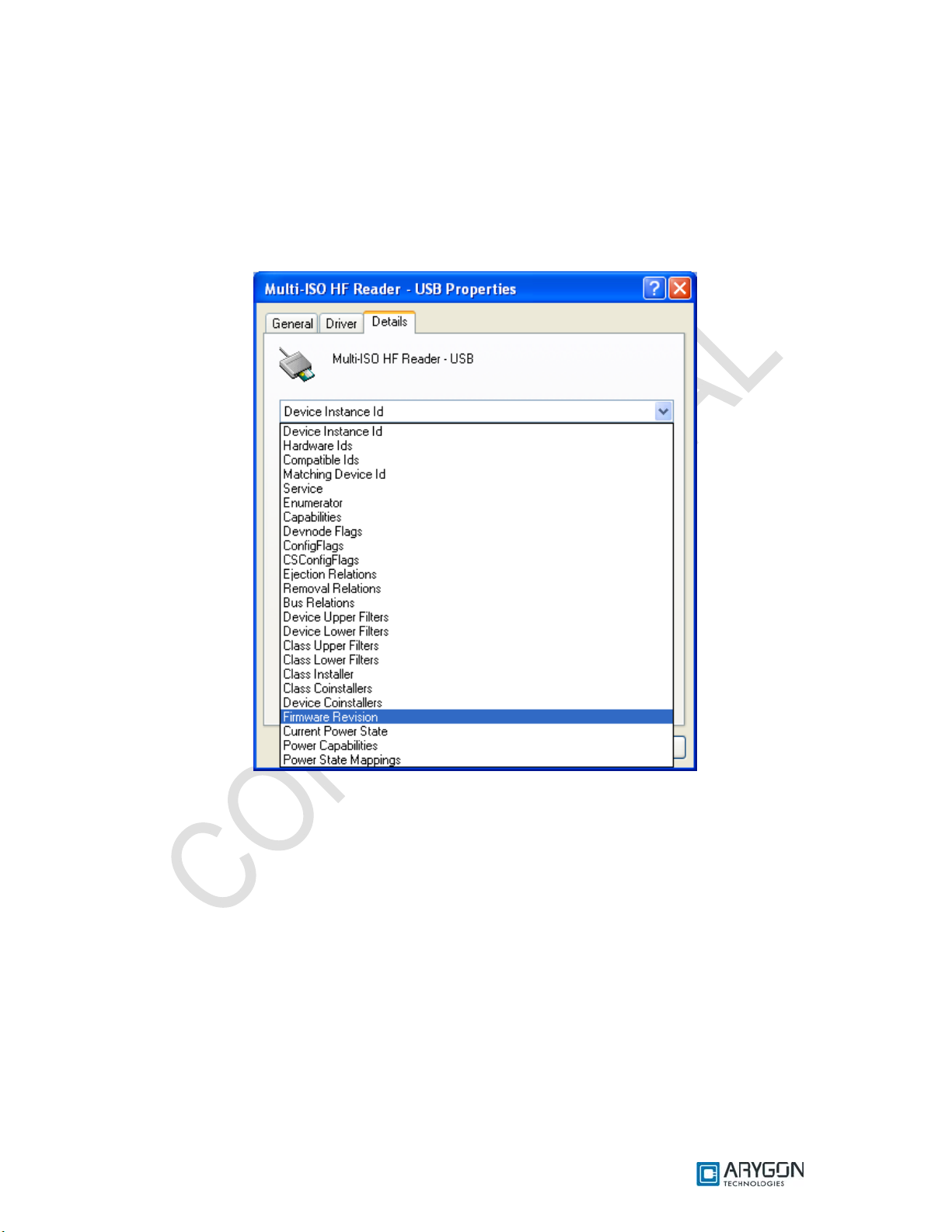
2.2 Firmware Version Detection
To detect the current version of the firmware in the device, follow the same procedures as in the
Driver version detection up to step 3.
1. In the dialog box which appears, select “Details” tab. And in the drop down list box select
“Firmware Revision” as shown below.
Version: 1.6 Page 11 of 48
Page 12
User_Manual - Multi-ISO_HF_Reader - USB_Ver1.6.doc- Confidential
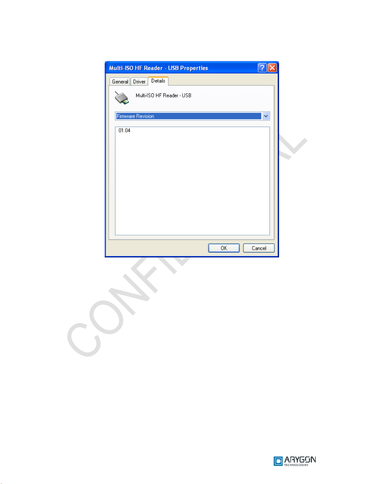
2. In the dialog box, the version of the firmware currently in the device will be displayed as
shown below
Version: 1.6 Page 12 of 48
Page 13

User_Manual - Multi-ISO_HF_Reader - USB_Ver1.6.doc- Confidential
3 Card Reader Suite – Test Application
CardRdrSuite is a test application that is provided along with Multi-ISO HF USB Reader/Writer
for customer use. CardRdrSuite consists of several sub-applications covering the following functions
3.1 Firmware Download
Reader firmware can be downloaded into the reader/writer using this sub-application. Salient
features are
• Auto reader detection
• User friendly GUI
• Provision to view device’s current firmware version and the version of the firmware to be
downloaded
The application operates in two modes
• DFU class mode
o Disaster recovery mode to recover reader if the reader is plugged out
accidentally during firmware download
o Individual DFU driver to handle this mode
• Proprietary mode
o Firmware download support without using the DFU driver
Refer to section “Firmware Download” of Card Reader Suite help file for detailed description.
Help file can be launched using the “Help” button in the main window of the Card Reader Suite
application.
3.2 Pcsc Diagnostics
Any Card APDU or Pseudo APD U can be issued and tested using this sub -application.
Salient features are
• APDU execution from script file (.APDU)
• Easy to edit script files
• Error status logging in a file
• Working sample scripts for each card type supported
Refer to section “Pcsc Diagnostics” of the Card Reader Suite help file for detailed description
Version: 1.6 Page 13 of 48
Page 14

User_Manual - Multi-ISO_HF_Reader - USB_Ver1.6.doc- Confidential
3.3 Binary configuration
All configurable parameters of the reader can be modified using these sub-applications. These
applications will configure the firmware binary file only.
Configure Binary
• Configures
o USB Chapter 09 parameters
o Firmware Version parameters
o Hardware Version parameters
o Other firmware configurations
• Provides option to make the parameters non-modifiable after config uring
Refer to section “Configure binary” of Card Reader Suite help file for detailed description
Edit Binary
• Configures
o RF parameters
o Mifare keys stored in the non-volatile memory of the reader
o DESFire keys stored in the non-volatile memory of the reader
• Provides option to make the parameters non-modifiable after config uring
Refer to section “Edit Binary” of Card Reader Suite help file for detailed description
Version: 1.6 Page 14 of 48
Page 15

User_Manual - Multi-ISO_HF_Reader - USB_Ver1.6.doc- Confidential
4 PCSC 2.0
“Multi-ISO HF USB Reader/Writer” can be accessed using the standard PCSC architecture for
communicating with cards. This makes card access easy, as it uses the same communication
procedure for all the cards.
The Microsoft Developer Network (MSDN) library gives valuable information and a detailed
description of all SCard APIs for communicating with the reader, through the Windows PCSC
framework (WINSCARD APIs – Refer [R4]).
4.1 How to Access Contactless Cards via PCSC?
Contactless cards can be easily accessed through PCSC using standard WINSCARD smart
card API’s for card access. The following steps provide guidelines for using the PCSC compliant
WINSCARD API’s to access cards using the Multi-ISO HF USB Reader/Writer.
4.1.1 Establish Context
This is the first step. This API will initialize all other PCSC APIs and allocate all resources
necessary for a smart card session. The SCardEstablishContext function establishes the resource
manager context (the scope) within which database operations is performed.
LONG SCardEstablishContext ( IN DWORD dwScope,
IN LPCVOID pvReserved1,
IN LPCVOID pvReserved2,
OUT LPSCARDCONTEXT phContext);
4.1.2 List Readers
The next step is to get a list of all PCSC readers connected to the system using the
SCardListReaders function. Look for “Multi-ISO HF Reader – USB - 0000000000000001 0”, in the list
returned. If multiple Multi-ISO HF USB Reader/Writers are connected to your system, they will be
enumerated with different serial numbers.
Example: “Arygon Multi-ISO 0000000000000001 0”, “Arygon Multi-ISO 0000000000000002 0”, could
be the list returned when the following function is executed.
LONG SCardListReaders (IN SCARDCONTEXT *phContext,
IN LPCTSTR mszGroups,
OUT LPTSTR mszReaders,
IN OUT LPDWORD pcchReaders);
Note: The OUT parameter phContext of SCardEstablishContext is used as in parameter for this API.
Version: 1.6 Page 15 of 48
Page 16

User_Manual - Multi-ISO_HF_Reader - USB_Ver1.6.doc- Confidential
4.1.3 Connect
Next step is to connect to the card via the reader/writer. The SCardConnect API establishes a
connection (using a speci fic resource man ager context ) between the cal ling applicat ion and a smart
card contained by the specific reader. If no card exists in the specified reader, an error is returned.
LONG SCardConnect ( IN SCARDCONTEXT *phContext,
IN LPCTSTR szReader,
IN DWORD dwShareMode,
IN DWORD dwPreferredProtocols,
OUT LPSCARDHANDLE phCard,
OUT LPDWORD pdwActiveProtocol);
Note: The OUT parameter phContext of SCardEstablishContext is used as in parameter for this API.
4.1.4 Data and Command transfer with Card
Command and data that are transferred to the card are called as APDUs (application protocol
data unit) in smart card terminology. The SCardTransmit function sends a service request to the smart
card, and expects data back from the card.
LONG SCardTransmit ( IN SCARDHANDLE *phCard,
IN LPCSCARD_I0_REQUEST pioSendPci,
IN LPCBYTE pbSendBuffer,
IN DWORD cbSendLength,
IN OUT LPSCARD_IO_REQUEST pioRecv Pci,
OUT LPBYTE pbRecvBuffer,
IN OUT LPDWORD pcbRecvLength);
Note: The OUT parameter phCard of SCardConnect is used as in parameter for this API.
4.1.5 Disconnect
It is not mandatory to disconnect the card after the completion of all transactions, but it is
recommended. The SCardDisconnect function terminates a connection previously opened between
the calling application and a smart card in the target reader.
LONG SCardDisconnect (IN SCARDHANDLE *phCard,
IN DWORD dwDisposition);
Note: The OUT parameter phCard of SCardConnect is used as in parameter for this API.
4.1.6 Release
This step ensures that all system resources are being released. The SCardReleaseContext
function closes an established resource manager context, freeing any resources allocated under that
context.
LONG SCardReleaseContext (IN SCARDCONTEXT *phContext);
Note: The OUT parameter phContext of SCardEstablishContext is used as in parameter for this API.
Version: 1.6 Page 16 of 48
Page 17

User_Manual - Multi-ISO_HF_Reader - USB_Ver1.6.doc- Confidential
4.2 ATR Generation
To make contactless cards available within the PCSC framework, the Multi-ISO HF USB
Reader/Writer generates a PCSC compliant ATR according to PCSC v2.01.09 “Interoperability
Specification for ICCs and Personal Computer Systems” (reference [R2])
4.2.1 CPU Cards
The ATR of Contactless processor cards are composed as described in PCSC v2.01.09,
Part3: Requirements for PC connected Interface Devices, 3.1.3.2.3.1, Table 3.5
4.2.2 Storage Cards
The ATR of storage cards (i.e. cards without CPU) are composed as described in PCSC
v2.01.09, Part3: Requirements for PC connected Interface Devices, 3.1.3.2.3.2, Table 3.6. In order to
allow the HOST application to identify a storage card type properly, its standard and card name is
mapped according to the Part3: Supplement Document of PCSC v2.01.04
Note:
The registered Application Provider Identifier (RID) returned by the Multi-ISO HF USB
Reader/Writer for storage cards (cards without CPU) is A0 00 00 03 06, which is the RID of the PCSC
workgroup
Version: 1.6 Page 17 of 48
Page 18

User_Manual - Multi-ISO_HF_Reader - USB_Ver1.6.doc- Confidential
5 Accessing Reader through PCSC
In some specific situations, PC/SC specifications are not enough to cover the whole functional
field. This happens typically
• When working with memory cards or even microprocessor based cards not following the ISO
7816-4 standard (APDU formalism)
• When needing to perform actions on to the reader/writer itself, and not onto the card (Like
modifying the RF parameters of the reader/writer)
In order to cover the above two cases, proprietary 7816 wrappers are supported. These are called
Pseudo APDUs. Refer to [R7] in order to understand the basic structure of APDU
Reader commands are covered under this section. While Pseudo APDU for accessing ISO 7816-
4 non-compliant cards are covered in Section 6
Mifare cards and I SO 156 93 ca rds use pro pri etar y 781 6 AP DU struc tur es. DESF ire c ards u se t he
7816 wrapper as described in the DESFire specifications [R3] & [R11]
All command and response bytes are sent and received as hexadecimal values respectively
Note:
In the pseudo APDUs described in this section, specifying a value of 00 in the Le field indicates
maximum no of available response bytes from the card, as described in reference [R7]
5.1 Reader Control Commands
The Reader/Writer control commands are used to modify the reader/writer parameters in order
to fine tune the reader/writer’s performance or to suit the end applications requirements. It follows
standard ISO 7816-4 (as per reference [R7]) command/ response format
The Reader/Writer control commands have the following general APDU format
Command Format:
CLA INS P1 P2 Lc Data Le
FF 00 00 00 No of bytes in
Data field
Response Format:
Data Status Word
Reader/Writer Control Response SW1 SW2
For possible values and description of status word refer Table 6.1
The following are the Reader/Writer control commands:
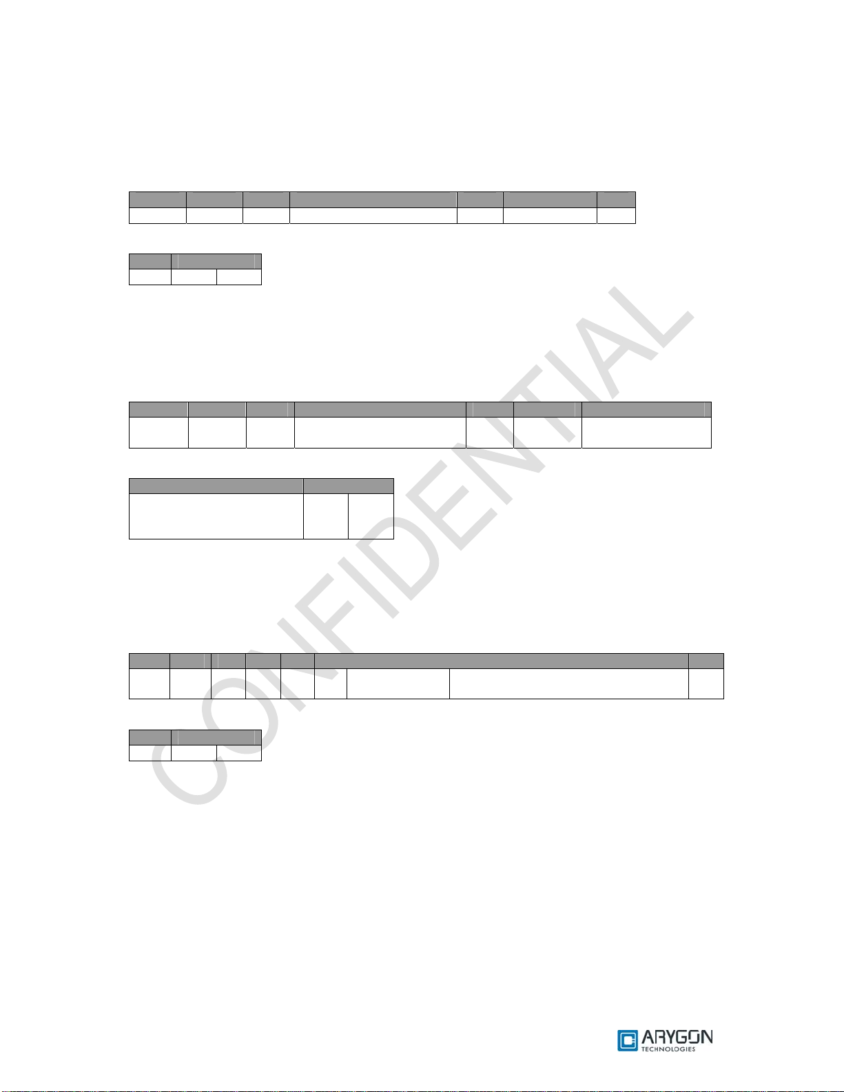
5.1.1 Get Static RF Parameters
Get Static RF Parameters command is used to get the RF parameters from the non-volatile
area of the reader/writer
Command Data:
CLA INS P1 P2 Lc Data Le
FF 00 00 00 03 01 00 03 00
Response Data:
Data Status
RF Parameters as in the Structure
shown in Table 4. 1 (1 2 8 by tes)
9000
Reader/Writer Control
Command
Command Parameters 00
Version: 1.6 Page 18 of 48
Page 19

User_Manual - Multi-ISO_HF_Reader - USB_Ver1.6.doc- Confidential
Note:
• The command fails if the reader/writer configuration is invalid
• The command fails if any of the command byte is invalid
5.1.2 Set Static RF Parameters
Set Static RF Parameters command is used to modify the RF parameters in the non-volatile
area of the reader/writer. The reader/writer uses these parameters from the next power ON
Command Data:
CLA INS P1 P2 Lc Data Le
FF 00 00 00 83 02 00 03 RF Pa rameters as in the Structure shown in Table
4.1 (128 bytes)
Response Data:
Data Status Word
- 9000
Note:
• In the above command data, modifying the parameter value 0300 might cause the
reader/writer to malfunction
• The command fails if the reader/writer configuration is invalid
• The command fails if any of the command byte is invalid
• The command fails if the length mentioned in the RF parameters structure is not equal to
0x0080
• Modifying the Flag value to anything other than 0x01, might make the reader/writer un-usable
-
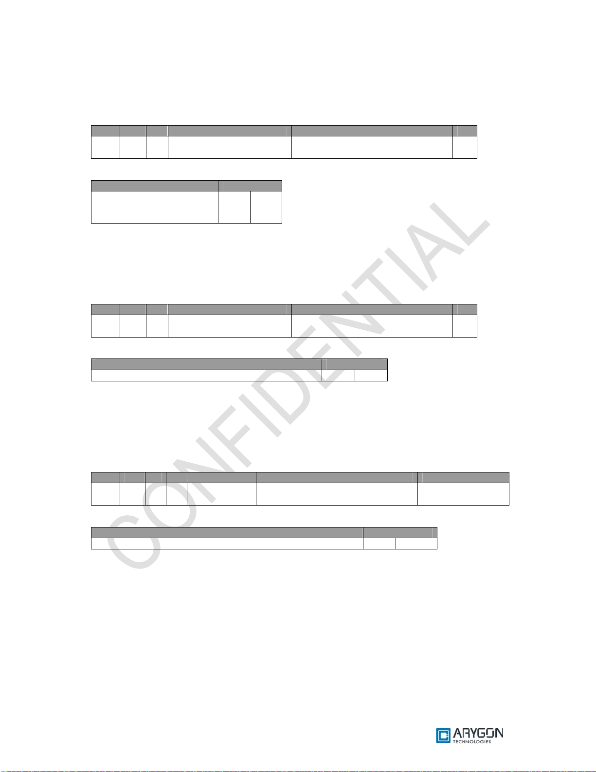
5.1.3 Get Dynamic RF Parameters
Get Dynamic RF Parameters command is used to get the RF parameters from the volatile
area of the reader/writer (current in use parameters)
Command Data:
CLA INS P1 P2 Lc Data Le
FF 00 00 00 01 03 - 00
Response Data:
Data Status Word
RF Parameters as in the Structure
shown in Table 4.1 (128 by tes)
9000
5.1.4 Set Dynamic RF Parameters
Set Dynamic RF Parameters command is used to modify the RF parameters in the volatile
area of the reader/writer (temporarily for this session). Immediately following this control command,
the reader/writer restarts its entire activity on the RF interface with the new parameters
Command Data:
CLA INS P1 P2 Lc Data Le
FF 00 00 00 81 04 RF Parameters as in the Structure
Shown in Table 4.1 (128 bytes)
Response Data:
Data Status Word
- 9000
Note:
• The command fails if the length mentioned in the RF parameters structure is not equal to
0x0080
-
Version: 1.6 Page 19 of 48
Page 20

User_Manual - Multi-ISO_HF_Reader - USB_Ver1.6.doc- Confidential
• The command fails if any of the command byte is invalid
5.1.5 RF Parameters Data Structure
Parameter
Length in bytes 2 [Value = 0x0080] 0
Flag 1 [Value = 0x01] 2
A106 - CWCONDUCTANCE 1 3
A106 – RXTHRESHOLD 1 4
A106 - RXCONTROL1 1 5
A212 - CWCONDUCTANCE 1 6
A212 - RXTHRESHOLD 1 7
A212 - RXCONTROL1 1 8
A424 - CWCONDUCTANCE 1 9
A424 - RXTHRESHOLD 1 10
A424 - RXCONTROL1 1 11
A828 - CWCONDUCTANCE 1 12
A828 - RXTHRESHOLD 1 13
A828 - RXCONTROL1 1 14
B106 - CWCONDUCTANCE 1 15
B106 - RXTHRESHOLD 1 16
B106 - RXCONTROL1 1 17
B106 - MODCONDUCTANCE 1 18
B106 - TYPEBFRAMING 1 19
B212 - CWCONDUCTANCE 1 20
B212 - RXTHRESHOLD 1 21
B212 - RXCONTROL1 1 22
B212 - MODCONDUCTANCE 1 23
B212 - TYPEBFRAMING 1 24
B424 - CWCONDUCTANCE 1 25
B424 - RXTHRESHOLD 1 26
B424 - RXCONTROL1 1 27
B424 - MODCONDUCTANCE 1 28
B424 - TYPEBFRAMING 1 29
B848 - CWCONDUCTANCE 1 30
B848 - RXTHRESHOLD 1 31
B848 - RXCONTROL1 1 32
B848 - MODCONDUCTANCE 1 33
B848 - TYPEBFRAMING 1 34
TESTANASELECT 1 35
TESTDIGISELECT 1 36
Reserved 11 37
RF Reset Width in milliseconds 2 48
Card de-bounce delay in milliseconds 2 50
All Timeout Values Multiplication scale 1 52
All Timeout Values Division scale 1 53
All constant Delay Multiplication scale 1 54
All constant Delay Division scale 1 55
All Loop counts Multiplication scale 1 56
All Loop counts Division scale 1 57
Type-A Max baud limit 1 58
Type-B Max baud limit 1 59
Card Polling scheme 1 60
Reserved 67 61
Table 4.1 RF parameters data structure
No of bytes
Offset
Version: 1.6 Page 20 of 48
Page 21

User_Manual - Multi-ISO_HF_Reader - USB_Ver1.6.doc- Confidential
Naming Convention
In the above table,
• The Parameters starting with ‘A’ or ‘B’ refer to the respective ISO 14443 card types
• The number following the alphabet indicates the baud rate at which the card should be
operating
• The actual RF parameter follows the ‘-’. This parameter will take effect for that type of card
operating at that baud rate
Example: - A106 – CWCONDUCTANCE indicates the CWCONDUCTANCE parameter of ISO 14443
TypeA cards operating at 106 Kbps
Parameter Description
RF Control Parameter:
“CWCONDUCTANCE” parameter controls the strength of RF field when there is no
modulation. Its value can vary from 0x00 to 0x3F. The chosen value would get directly programmed
into the (Address 0x12) RFID reader silicon. For more details refer to the respective datasheet of
RFID reader silicon (reference [R12]).
“RXTHRESHOLD” parameter controls the receiver input threshold levels. The specified value
would get dir ectly program med into the (Add ress 0x1 C) RFID reader silicon. For more details refer to
the respective datasheet of RFID reader silicon (reference [R12]).
“RXCONTROL1” parameter controls the receiver input stage gain levels and the low pass
filters. The specified value would get directly programmed into the (Address 0x19) RFID reader silicon.
For more details refer to the respective datasheet of RFID reader silicon (reference [R12]).
“MODCONDUCTANCE” parameter controls the strength of RF field when there is 10%
modulation for Type-B data transmission. Its value can vary from 0x00 to 0x3F. The chosen value
would get directly programmed into the (Address 0x13) RFID reader silicon. For more details refer to
the respective datasheet of RFID reader silicon (reference [R12]).
“TYPEBFRAMING” parameter controls the framing headers SOF & EOF of type B
transmission frames. The specified value would get directly programmed into the (Address 0x17)
RFID reader silicon. For more details refer to the respective datasheet of RFID reader silicon
(reference [R12]).
“TESTANASELECT” parameter controls the analog debug output pin AUX. The specified
value would get directly programmed into the (Address 0x3A) RFID reader silicon. For more details
refer to the respective datasheet of RFID reader silicon (reference [R12]).
“TESTDIGISELECT” parameter controls the digital debug output pin MFOUT. The specified
value would get directly programmed into the (Address 0x3D) RFID reader silicon. For more details
refer to the respective datasheet of RFID reader silicon (reference [R12]).
RF Reset Width in milliseconds:
This parameter defines the width of RF Reset (no RF Power) during the polling sequence.
The value entered is in decimal, from 0 to 65535. The RF reset would have a width of this much
amount of time in milliseconds.
Card de-bounce delay in milliseconds:
This parameter defines the time in milliseconds for which the card arrival is polled and
reconfirmed by repeated RNAK polling, before notifying the arrival of a new card into the RF field, to
the host. The value entered is in decimal, from 0 to 65535.
Version: 1.6 Page 21 of 48
Page 22

User_Manual - Multi-ISO_HF_Reader - USB_Ver1.6.doc- Confidential
All Timeout values Multiplication scale & All Timeout values Division scale:
These two parameters are used to scale the Timeout values used by the Wait functions. The
scaling is done using the following formula:
TIMEOUT =
All constant Delay Multiplication scale & All constant Delay Division scale:
These two para meters are used t o scale t he const ant Del ays used i n the Wait funct ions. T he
scaling is done using the following formula:
CONSTDELAY =
All Loop counts Multiplication scale & All Loop counts Division scale:
Under ISO 14443 Part 3 & Part 4, on occurrence of any communication errors like CRC,
Framing, Parity and Timeout, the command will be re-tried by the reader/writer. The Retry count value
is scaled using these two parameters, as per the following formula:
RETRYCOUNT =
Type-A Max baud limit & Type-B Max baud limit:
This parameter is used to limit the maximum baud rate at which the reader/writer can operate
with the respective ISO 14443 card types
Card Polling Scheme:
This parameter enables the user to select the card types he wants the reader/writer to detect.
The Card type s disabled he re will not be detected
b7 b6 b5 b4 b3 b2 b1 b0 Polling Scheme
0 0 0 0 0 0 0 0 No Polling
X X X X X X X 1 Poll for 14443 TypeA cards
X X X X X X 1 X Poll for 14443 TypeB cards
X X X 1 X X X X Poll for ISO 15693 cards
1 X X X X X X X Stay in Polling
Timeout * Timeout Multiplication Scale
Timeout Division Scale
DefaultRetryCount * Loop Count Multiplication
DefaultRetryCount * Loop Count Multiplication
Value Maximum Baud Rate Supported
0x00 106 Kbps
0x01 212 Kbps
0x02 424 Kbps
0x03 848 Kbps
Version: 1.6 Page 22 of 48
Page 23

User_Manual - Multi-ISO_HF_Reader - USB_Ver1.6.doc- Confidential
5.2 Key Management
The Multi-ISO HF USB Reader/Write r provides provision to store card keys in its non-volatile
memory. The reader can be customized to store card keys. An authenticated user can later refer to
them during card communication using key numbers. This section describes the commands used to
achieve this functionality in detail
5.2.1 Reader Authentication
The Reader Authenticate command is used to authenticate with the reader/writer. The PIN
specified in the command is verified with the PIN stored in the reader/writer
Only after a successful Reader Authenticate, the user can use the Load Keys command to
store card specific keys or modify the Reader PIN in the non-volatile area of the reader/writer
This command is used to ensure that a malicious user does not gain access to modify the
Card keys or Reader PIN stored in the reader/writer.
Command Format:
CLA INS P1 P2 Lc Data Le
FF 00 00 00 09 09 Reader PIN
(8 bytes)
Response Format:
Data Status Word
- SW1 SW2
For possible values and description of status word refer Table 6.1
Note:
The Authentication state will be cleared immediately after the first Load Keys command
following the Reader Authenticate command, irrespective of whether the Load Keys command was
successful or not. The user will have to authenticate with the reader/writer before issuing each Load
Keys command
-
Version: 1.6 Page 23 of 48
Page 24

User_Manual - Multi-ISO_HF_Reader - USB_Ver1.6.doc- Confidential
5.2.2 Load Keys
The Load Keys command is used to store Mifare keys, DESFire keys and Reader PIN in the
non-volatile area of the reader/writer.
The user must use Reader Authenticate command (described in section 5.1) to authenticate
with the reader/writer before using this command
The reader/writer has provision to store 1 Reader PIN (8 bytes), 80 Mifare Keys along with
Key type and 8 DE SFire TDES key s ( 1 P I C C M as ter key and 7 App l i c at i o n k e ys) along wit h AI D , P C D
Key number and PICC Key number.
When a card spec ific Authen ticate APDU is received from the host , the appropr iate keys are
fetched from the non-volatile memory pf the reader and used for authentication
This command does not require the presence of a card over the reader; however it may also do so.
Command Format:
CLA INS P1 P2 Lc Data Le
FF 00 00 00 No of bytes in
Data field
Response Format:
Data Status Word
- SW1 SW2
For possible values and description of status word refer Table 6.1
Note:
The user must make sure that he uses the Load Keys command to store the appropriate keys
(Mifare or DESFire) in the reader/writer before trying to issue an Authenticate APDU to the respective
card
07 Key Data
-
5.2.2.1 Load Reader Authentication PIN in to Reader
The Following is the Load Keys command format to change the reader PIN. The Reader PIN
can be any 8 byte numeric value
Command Data:
CLA INS P1 P2 Lc Data Le
FF 00 00 00 0A 07 FF Reader PIN (8
bytes)
Example:
Change Reader PIN in the reader
Command: FF 00 00 00 0A 07 FF 01 02 03 04 05 06 07 0 8
Response: 90 00
-
5.2.2.2 Load Mifare Authentication Keys in to Reader
The following is the Load Keys command format to load the Mifare authentication keys into the reader
Command Data:
CLA INS P1 P2 Lc Data Le
FF 00 00 00 0A 07 00 Mifare Key data
(as shown below)
-
Version: 1.6 Page 24 of 48
Page 25

User_Manual - Multi-ISO_HF_Reader - USB_Ver1.6.doc- Confidential
Mifare Key data:
Key Data
Key Number
(1 Byte)
Where,
Key Number - any value from 00 to 4F
Key Type - 60 (Key Type A) or 61 (Key Type B)
Example:
Command for loading Mifare Keys with PCD Key Number = 00, Key Type = Key A
Command: FF 00 00 00 0A 07 00 00 60 FF FF FF FF FF FF
Response: 90 00
Key Type
(1 Byte)
Key
(6 Bytes)
5.2.2.3 Load DESFire Authentication Keys in to Reader
The following is the Load Keys command format to load DESFire authentication keys into the reader
Command Data:
CLA INS P1 P2 Lc Data Le
FF 00 00 00 1F 07 01 DESFire Key data
(as shown below)
DESFire Key data:
PCD Key No AID PICC Key No KEY Data
PCD Key No
(1 byte)
Where,
PCD Key No - any value from 00 to 07
AID - Application identifier in the card to which the Key belongs
PICC Key No - Key No to be used in the DESFire Authenticate command
TDES Keys - Key1 (8 bytes), Key2 (8 bytes) & Key3 (8 bytes). Key1 == Key3
Example 1:
Command – Loading TDES PICC Master Key with AID = 000000, PCD Key No = 00, PICC
Key No = 00
Command: FF 00 00 00 1F 07 01 00 00 00 00 00 11 22 33 44 55 66 77 88 12 34 56
78 12 34 56 78 11 22 33 44 55 66 77 88
Response: 90 00
Example 2:
Command – Loa ding TDE S PICC App licatio n_1 Key with AID = A1B1C1, PCD Key No = 01,
PICC Key No = 00
Command: FF 00 00 00 1F 07 01 01 A1 B1 C1 00 11 22 33 44 55 66 77 88 12 34
56 78 12 34 56 78 11 22 33 44 55 66 77 88
Response: 90 00
Note:
RdrLoadKeys will fail if any of the command parameters is invalid
AID
(3 bytes)
o Key no 00 refers to TDES PICC Master Key
o Key no’s 01 to 07 refer to TDES Application Keys
o Must be 000000 for PICC Master Key
PICC Key No
(1 byte)
TDES Key
(24 bytes)
-
Version: 1.6 Page 25 of 48
Page 26

User_Manual - Multi-ISO_HF_Reader - USB_Ver1.6.doc- Confidential
6 Accessing Cards through PCSC
Mifare cards and ISO 15693 cards use proprietary 7816 APDU structures. DESFire cards use
the 7816 wrapper as described in the DESFire specifications [R3] & [R11]
All command and response bytes are sent and received as hexadecimal values respectively
Note:
In the pseudo APDUs described in this section, specifying a value of 00 in the Le field indicates
maximum no of available response bytes from the card, as described in reference [R7]
6.1 Mifare Cards
Pseudo APDUs supported for Mifare cards are explained in this section
6.1.1 Authenticate
This APDU performs three pass authentication with the card for the Block No. specified in the
data field. It uses the Key of the Key no specified
Command APDU:
CLA INS P1 P2 Lc Data Le
FF 86 00 00 05 See Table below (5 bytes) -
Data:
Byte 1 Byte 2 Byte 3 Byte 4 Byte 5
01 Block No (MSB) Block No (LSB) 00 Key No.
Where,
Block No - Block number of the Mifare card which is to be authenticated
Key No - Key number specified in the RDRLoadKeys command to store the corresponding
Authentication key in the non-volatile area of the reader/writer
Response:
Data Status Word
- SW1 SW2
For possible values and description of status word refer Table 6.1
Version: 1.6 Page 26 of 48
Page 27
User_Manual - Multi-ISO_HF_Reader - USB_Ver1.6.doc- Confidential
6.1.2 Write Binary
This APDU writes data to the Mifare Block no specified
Command APDU:
CLA INS P1 P2 Lc Data Le
FF D6 00 Mif are Block No 10 Data to Card -
Response:
Data Status Word
- SW1 SW2
For possible values and description of status word refer Table 6.1
6.1.3 Read Binary
This APDU reads data from the Mifare Block no specified
Command APDU:
CLA INS P1 P2 Lc Data Le
FF B0 00 Mifare Block No - - Expected no of
bytes from card
Response:
Data Status Word
Data from the specified
block
in the Mifare card
For possible values and description of status word refer Table 6.1
SW1 SW2
6.1.4 Value Increment
This APDU increments the data in a Value block, using the 4 byte value specified
Command APDU:
CLA INS P1 P2 Lc Data Le
FF FC 00 00 06 C1 Mifare Block
No
Response:
Data Status Word
- SW1 SW2
For possible values and description of status word refer Table 6.1
4 bytes of value to be added to the
block value
-
Version: 1.6 Page 27 of 48
Page 28

User_Manual - Multi-ISO_HF_Reader - USB_Ver1.6.doc- Confidential
6.1.5 Value Decrement
This APDU decrements the data in a Value block, using the 4 byte value specified
Command APDU:
CLA INS P1 P2 Lc Data Le
FF FC 00 00 06 C0 Mifare Block
No
Response:
Data Status Word
- SW1 SW2
For possible values and description of status word refer Table 6.1
Note:
The Pseudo APDUs for Authenticate, Write Binary and Read Binary described in this section
are as defined in the PCSC v2.01.09, Part3: Requirements for PC connected Inte rface Devices, under
section 3.2.2.1
4 bytes of value to be subtracted from
the block value
-
Version: 1.6 Page 28 of 48
Page 29

User_Manual - Multi-ISO_HF_Reader - USB_Ver1.6.doc- Confidential
6.2 ISO 15693 Cards
Pseudo APDUs supported for ISO 15693 cards are explained in this section
6.2.1 Read Single Block
This APDU reads 4 bytes of data from the bloc k no specified
Command APDU:
CLA INS P1 P2 Lc Data Le
FF FC 00 00 No of bytes in Data
field
Response:
Data Status Word
Read single block response
as described in reference
[R1]
For possible values and description of status word refer Table 6.1
SW1 SW2
Read single block command as
described in reference [R1]
Expected no of
bytes from card
6.2.2 Write Single Block
This APDU writes 4 bytes of data to the block no specified
Command APDU:
CLA INS P1 P2 Lc Data Le
FF FC 00 00 No of bytes in Data
field
Response:
Data Status Word
Write single block response as described in reference
[R1]
For possible values and description of status word refer Table 6.1
Write single block command as
described in reference [R1]
SW1 SW2
-
6.2.3 Lock Block
This APDU Locks the specified Block no. Once successfully locked, the block will become read only
Command APDU:
CLA INS P1 P2 Lc Data Le
FF FC 00 00 No of bytes in Data
field
Response:
Data Status Word
Lock block response as described in reference [R1] SW1 SW2
For possible values and description of status word refer Table 6.1
Lock block command as described in
reference [R1]
-
Version: 1.6 Page 29 of 48
Page 30

User_Manual - Multi-ISO_HF_Reader - USB_Ver1.6.doc- Confidential
6.2.4 Read Multiple Blocks
This APDU reads 4 bytes of data from each of the requested no of blocks, starting from the block no
specified
Command APDU:
CLA INS P1 P2 Lc Data Le
FF FC 00 00 No of bytes in Data
field
Response:
Data Status Word
Read multiple block response as described in reference [R1] S W1 SW2
For possible values and description of status word refer Table 6.1
Read multiple block command as
described in reference [R1]
Expected no of
bytes from card
Version: 1.6 Page 30 of 48
Page 31
User_Manual - Multi-ISO_HF_Reader - USB_Ver1.6.doc- Confidential
6.2.5 Write AFI
This APDU writes the AFI value specified into the card’s memory
Command APDU:
CLA INS P1 P2 Lc Data Le
FF FC 00 00 No of bytes in Data
field
Response:
Data Status Word
Write AFI response
as described in reference
[R1]
For possible values and description of status word refer Table 6.1
SW1 SW2
Write AFI command as described in
reference [R1]
6.2.6 Write DSFID
This APDU writes the DSFID value specified into the card’s memory
Command APDU:
CLA INS P1 P2 Lc Data Le
FF FC 00 00 No of bytes in Data
field
Response:
Data Status Word
Write DSFID response as described in reference [R1] SW1 SW2
For possible values and description of status word refer Table 6.1
Write DSFID command as described
in reference [R1]
-
-
6.2.7 Get System Information:
This APDU retrieves system information, like UID, DSFID, AFI, Memory information, IC
Manufacturer code etc from the card
Command APDU:
CLA INS P1 P2 Lc Data Le
FF FC 00 00 No of bytes in
Data field
Response:
Data Status Word
Get system information response as described in reference [R1] SW1 SW2
For possible values and description of status word refer Table 6.1
Get system information command as
described in reference [R1]
Expected no of
bytes from card
Version: 1.6 Page 31 of 48
Page 32

User_Manual - Multi-ISO_HF_Reader - USB_Ver1.6.doc- Confidential
6.2.8 Get Multiple Block Security Status:
This APDU retrieves the block security status of each of the requested no of blocks, starting from the
block no specified
Command APDU:
CLA INS P1 P2 Lc Data Le
FF FC 00 00 No of bytes in
Data field
Response:
Data Status Word
Get multiple block security status response as described in
reference [R1]
For possible values and description of status word refer Table 6.1
Note:
In all the above 15693 card commands, the optional Flags byte and optional UID field must be
omitted. In all the above 15693 card responses, Flags byte will be omitted and Error Code (if any)
will be sent as SW2
Get multiple block security status command as
described in reference [R1]
SW1 SW2
00
Version: 1.6 Page 32 of 48
Page 33

User_Manual - Multi-ISO_HF_Reader - USB_Ver1.6.doc- Confidential
6.3 Crypto RF Cards
Pseudo APDUs supported for Atmel CryptoRF cards are explained in this section
6.3.1 Set User Zone
This APDU selects the specified user Zone. All further user zone operations will be done in
the selected user zone. The command is also used to enable anti-tearing mode, following which all
writes to this user zone will use anti-tearing
Command APDU:
CLA INS P1 P2 Lc Data Le
FF FC 00 00 No of bytes in
Data field
Response:
Data Status Word
Set User Zone response as per reference [R10] SW1 SW2
For possible values and description of status word refer Table 6.1
6.3.2 Read User Zone
This APDU reads data from the currently selected user zone
Command APDU:
CLA INS P1 P2 Lc Data Le
FF FC 00 00 No of bytes in
Data field
Response:
Data Status Word
Read User Zone response as per reference [R10] SW1 SW2
For possible values and description of status word refer Table 6.1
6.3.3 Write User Zone
This APDU writes data to the currently selected user zone. In anti-tearing mode the maximum
no of bytes that can be written is 8 bytes
Command APDU:
CLA INS P1 P2 Lc Data Le
FF FC 00 00 No of bytes in
Data field
Response:
Data Status Word
Write User Zone response as per reference [R10] SW1 SW2
For possible values and description of status word refer Table 6.1
Set User Zone Command as per
reference [R10]
Read User Zone Command
as per reference [R10]
Write User Zone Command as
per reference [R10]
-
Expected no of bytes from
card
-
Version: 1.6 Page 33 of 48
Page 34

User_Manual - Multi-ISO_HF_Reader - USB_Ver1.6.doc- Confidential
6.3.4 Read System Zone
This APDU reads system data from the configuration memory of the card. Depending on the
value of the PARAM byte (part of the command), this command may read data from the configuration
zone, the fuses or a checksum
Command APDU:
CLA INS P1 P2 Lc Data Le
FF FC 00 00 No of bytes in
Data field
Response:
Data Status Word
Read System Zone response as per reference [R10] SW1 SW2
For possible values and description of status word refer Table 6.1
Read System Zone Command
as per reference [R10]
Expected no of bytes from
card
6.3.5 Write System Zone
This APDU writes data to the configuration memory. Depending on the value of the PARAM
byte (part of the command), this command may write data to the configuration zone or program fuses.
The anti-tearing mode can also be enabled using the PARAM byte. The maximum number of bytes
that can be written in anti-tearing mode is 8 bytes
Command APDU:
CLA INS P1 P2 Lc Data Le
FF FC 00 00 No of bytes in
Data field
Response:
Data Status Word
Write System Zone response as per reference [R10] SW1 SW2
For possible values and description of status word refer Table 6.1
Write Syst em Zone Command as
per reference [R10]
-
6.3.6 Check Password
This APDU is use d to send the password f or validation agains t the password select ed with
the password index byte (part of the command). This command is used to gain access, to read or
write in user zones that require password validation
Command APDU:
CLA INS P1 P2 Lc Data Le
FF FC 00 00 No of bytes in
Data field
Response:
Data Status Word
Check Password response as per reference [R10] SW1 SW2
For possible values and description of status word refer Table 6.1
Note:
In all the above CryptoRF card commands, the CID field (higher nibble of the command byte),
must be set to 0. In all the above CryptoRF card responses, the Command byte and ACK/NACK byte
will be omitted. Status byte will be sent as SW2
Check Password Command as
per reference [R10]
-
Version: 1.6 Page 34 of 48
Page 35

User_Manual - Multi-ISO_HF_Reader - USB_Ver1.6.doc- Confidential
6.4 DESFire Cards
For DESFire cards, the Multi-ISO HF USB Reader/Writer supports the 7816-4 APDU wrapper
as describe d in the DESFire specification (as per reference [R3]).
6.5 Generic APDUs
This section describes the generic Pseudo APDUs used with all supported cards
6.5.1 Get UID
This APDU retrieves the card Unique ID (UID). Length of the UID varies depending on the card
Command APDU:
CLA INS P1 P2 Lc Data Le
FF CA 00 00 - - 00
Response:
Data Status Word
UID of the Card SW1 SW2
For possible values and description of status word refer Table 6.1
6.5.2 Traverse
This APDU is used to send the “Raw Card Command“ in the data field to the card without any
command specific processing by the reader/writer and returns the response data f rom the Card. The
reader/writer only takes care of the protocol specific processing (CRC, Prologue field etc ...)
The reader/writer uses the Frame type specified in the P2 parameter field and the Frame
waiting time specified in the P1 parameter field, while sending the command and receiving the
response, respectively
Command APDU:
CLA INS P1 P2 Lc Data Le
FF FD FWT Code (as
defined in the table
below)
Frame Type (as defined
in the table below)
No of data bytes
sent to the card
Raw Card
Command
00
Version: 1.6 Page 35 of 48
Page 36

User_Manual - Multi-ISO_HF_Reader - USB_Ver1.6.doc- Confidential
FWT:
FWT
FWT (in microseconds)
Code
00 500
01 1000
02 2000
03 5000
04 10000
05 25000
06 50000
07 75000
08 100000
09 250000
0A 500000
0B 750000
0C 1000000
0D 1250000
0E 1500000
0F 1750000
10 2000000
11 2500000
12 3000000
13 4000000
14 5000000
Frame Type:
Frame
Description
Type
00 FRAMETYPE_SHORT
01 FRAMETYPE_STD
01 FRAMETYPE_ACBITORIENTED
Response:
The response from the card is returned as such without any processing. Reception of any
response from the card is considered as success irrespective of the content of the response
Data Status Word
Response from Card SW1 SW2
For possible values and description of status word refer Table 6.1
Version: 1.6 Page 36 of 48
Page 37

User_Manual - Multi-ISO_HF_Reader - USB_Ver1.6.doc- Confidential
6.6 Status Word
Status Word (HEX)
SW1 SW2
90 00 Command Successful
63 00 Reason for error unknown
69 83 Authentication is required to access the block in the card
69 82 Block’s security status prevents access
69 88 Wrong key no. was specified to authenticate with the block
67 00 Length parameter in the APDU is wrong
68 00 Class byte in the APDU is wrong
6B 00 Invalid parameter in the APDU
6A 81 Command is not supported
6C XX Wrong Le field. Actual Le is mentioned in place of XX
6F 00 No Precise diagnos is
6D 00 Instruction code not supported or invalid
Description
Table 6.1 Status Word Description
Version: 1.6 Page 37 of 48
Page 38

User_Manual - Multi-ISO_HF_Reader - USB_Ver1.6.doc- Confidential
7 APDU Samples to Access Cards
The basic card access sequence using would be:
• Connect to the card using SCardConnect API
• Send commands to the card using SCardTransmit API
• Use SCardDisconnect API to disconnect from the card
7.1 How to access MIFARE classic cards?
Get Uid
Command: FF CA 00 00 00
Response: XX XX XX XX 90 00
Reader Authenticate (PIN : '0000000000000000')
Command: FF 00 00 00 09 09 00 00 00 00 00 00 00 00
Response: 90 00
Mifare Load Keys (PCD Key No. : 00, Key Type : Key A)
Command: FF 00 00 00 0A 07 00 00 60 FF FF FF FF FF FF
Response: 90 00
Authenticate (Block No. : 001E, PCD Key No. : 00)
Command: FF 86 00 00 05 01 00 1E 00 00
Response: 90 00
Read Binary - Traverse (Block No. : 1E)
Command: FF FD 0A 01 02 30 1E 00
Response: XX XX XX XX XX XX XX XX XX XX XX XX XX XX XX XX 90 00
Read Binary (Block No. : 1E)
Command: FF B0 00 1E 00
Response: XX XX XX XX XX XX XX XX XX XX XX XX XX XX XX XX 90 00
Read Binary (Block No. : 1E)
Command: FF B0 00 1E 10
Response: XX XX XX XX XX XX XX XX XX XX XX XX XX XX XX XX 90 00
Write Binary (Block No. : 1E)
Command: FF D6 00 1E 10 01 02 03 04 05 06 07 08 09 10 11 12 13 14 15 16
Response: 90 00
Read Binary (Block No. : 1E)
Command: FF B0 00 1E 00
Response: XX XX XX XX XX XX XX XX XX XX XX XX XX XX XX XX 90 00
Write Binary (Block No. : 1E)
Command: FF D6 00 1E 10 A1 B2 C3 D4 E5 F6 1F 2E 3D 4C 5B 6A BB CC DD EE
Response: 90 00
Read Binary (Block No. : 1E)
Command: FF B0 00 1E 00
Response: XX XX XX XX XX XX XX XX XX XX XX XX XX XX XX XX 90 00
Prepare Block as value block (Block No. : 1E, Value : 64000000)
Command: FF D6 00 1E 10 64 00 00 00 9B FF FF FF 64 00 00 00 00 FF 00 FF
Response: 90 00
Version: 1.6 Page 38 of 48
Page 39

User_Manual - Multi-ISO_HF_Reader - USB_Ver1.6.doc- Confidential
Value Increment (Block No. : 1E)
Command: FF FC 00 00 06 C1 1E 01 00 00 00
Response: 90 00
Value Decrement (Block No. : 1E)
Command: FF FC 00 00 06 C0 1E 01 00 00 00
Response: 90 00
7.2 How to access MIFARE UL cards?
Get Uid
Command: FF CA 00 00 00
Response: XX XX XX XX XX XX XX 90 00
Read Binary (Block No. : 09)
Command: FF B0 00 09 00
Response: xx xx xx xx 90 00
Read Binary Traverse (Block No. : 09)
Command: FF FD 0A 01 02 30 09 00
Response: XX XX XX XX XX XX XX XX XX XX XX XX XX XX XX XX 90 00
Write Binary (Block No. : 09)
Command: FF D6 00 09 04 01 02 03 04
Response: 90 00
Read Binary (Block No. : 09)
Command: FF B0 00 09 00
Response: XX XX XX XX 90 00
Write Binary (Block No. : 09)
Command: FF D6 00 09 10 A1 B2 C3 D4 01 01 01 01 01 01 01 01 01 01 01 01
Response: 90 00
Read Binary (Block No. : 09)
Command: FF B0 00 09 00
Response: xx xx xx xx 90 00
Version: 1.6 Page 39 of 48
Page 40

User_Manual - Multi-ISO_HF_Reader - USB_Ver1.6.doc- Confidential
7.3 How to access DESFIRE cards?
Select Application (AID : '000000')
Command: 90 5A 00 00 03 00 00 00 00
Response: 91 00
Authenticate (PICC Key No. : 00)
Command: 900A0000010000
Response: 9100
Change Key (PICC Key No. : 00)
Command: 90 C4 00 00 19 00 11 11 11 11 11 11 11 11 22 22 22 22 22 22 22 22 11 11 11 11 11 11
11 11 00
Response: 91 00
GetKeyVersion (PICC Key No. : 00)
Command: 90 64 00 00 01 00 00
Response: xx 91 00
Create DES/TDES Application (AID : 'C3C2C1')
Command: 90 CA 00 00 05 C1 C2 C3 0F 07 00
Response: 91 00
ReaderAuthenticate (PIN : '0000000000000000')
Command: FF 00 00 00 09 09 00 00 00 00 00 00 00 00
Response: 90 00
Desfire Load Keys (PCD Key No. : 01, AID : 'C3C2C1', PICC Key No. : 00)
Command:F0 00 00 00 1F 07 01 01 C1 C2 C3 00 00 00 00 00 00 00 00 00 00 00 00 00 00 00 00 00
00 00 00 00 00 00 00 00
Response: 90 00
ReaderAuthenticate (PIN : '0000000000000000')
Command: FF 00 00 00 09 09 00 00 00 00 00 00 00 00
Response: 90 00
Desfire Load Keys (PCD Key No. : 02, AID : 'C3C2C1', PICC Key No. : 01)
Command:F0 00 00 00 1F 07 01 02 C1 C2 C3 01 00 00 00 00 00 00 00 00 00 00 00 00 00 00 00 00
00 00 00 00 00 00 00 00
Response: 90 00
ReaderAuthenticate (PIN : '0000000000000000')
Command: FF 00 00 00 09 09 00 00 00 00 00 00 00 00
Response: 90 00
Desfire Load Keys (PCD Key No. : 03, AID : 'C3C2C1', PICC Key No. : 02)
Command: F0 00 00 00 1F 07 01 03 C1 C2 C3 02 00 00 00 00 00 00 00 00 00 00 00 00 00 00 00 00
00 00 00 00 00 00 00 00
Response: 90 00
Select Application (AID : 'C3C2C1')
Command: 90 5A 00 00 03 C1 C2 C3 00
Response: 91 00
Authenticate (PICC Key No. : 00)
Command: 90 0A 00 00 01 00 00
Response: 91 00
Version: 1.6 Page 40 of 48
Page 41

User_Manual - Multi-ISO_HF_Reader - USB_Ver1.6.doc- Confidential
ChangeKeySettings (Free Access)
Command: 90 54 00 00 01 0F 00
Response: 9100
Change Key (PICC Key No. : 02)
Command: 90 C4 00 00 19 02 FF FF FF FF FF FF FF FF AA AA AA AA AA AA AA AA FF FF FF FF
FF FF FF FF 00
Response: 9100
Change Key (PICC Key No. : 00)
Command: 90 C4 00 00 19 00 AA AA BB BB CC CC DD DD EE EE FF FF 11 11 22 22 AA AA BB
BB CC CC DD DD 00
Response: 91 00
Authenticate (PICC Key No. : 02)
Command: 90 0A 00 00 01 02 00
Response: 91 00
Authenticate (PICC Key No. : 00)
Command: 90 0A 00 00 01 00 00
Response: 91 00
Create StdData File (File No. : 01)
Command: 90 CD 00 00 07 01 00 EE EE FF 02 00 00
Response: 91 00
Create Value File (File No. : 02)
Command: 90 CC 00 00 11 02 00 EE EE 00 00 00 00 FF 00 00 00 00 00 00 00 01 00
Response: 91 00
Create Linear Record File (File No. : 03)
Command: 90 C1 00 00 0A 03 00 EE EE 20 00 00 08 00 00 00
Response: 91 00
Change File Settings (File No. : 01, Comm Mode : Encrypted)
Command: 90 5F 00 00 04 01 03 0E 00 00
Response: 91 00
Write Data (File No. : 01)
Command: 90 3D 00 00 87 01 00 01 00 80 00 00 AA AA BB BB CC CC DD DD AA AA BB BB CC
CC DD DD AA AA BB BB CC CC DD DD AA AA B BB BC CC CD DD DA AA AB BB B CC CC DD
DD AA AA BB BB CC CC DD DD AA AA BB BB CC CC DD DD AA AA BB BB CC CC DD DD AA AA
BB BB CC CC DD DD AA AA BB BB CC CC DD DD AA AA BB BB CC CC DD DD AA AA BB BB CC
CC DD DD AA AA BB BB CC CC DD DD AA AA BB BB CC CC DD DD AA AA BB BB CC CC DD DD
AA AA BB BB CC CC DD DD 00
Response: 91 00
Read Data (File No. : 01)
Command: 90 BD 00 00 07 01 00 00 00 F4 01 00 00
Response: xx xx xx xx xx xx xx xx xx xx xx xx xx xx xx xx xx xx xx xx xx xx xx xx xx xx xx xx xx x x xx
xx xx xx xx xx xx xx xx xx xx xx xx xx xx xx xx xx xx xx xx xx xx xx xx xx xx xx xx xx xx xx xx xx xx xx
xx xx xx xx xx xx xx xx xx xx xx xx xx xx xx xx xx xx xx xx xx xx xx xx xx xx xx xx xx xx xx xx xx xx xx
xx xx xx xx xx xx xx xx xx xx xx xx xx xx xx xx xx xx xx xx xx xx xx xx xx xx xx xx xx xx xx xx xx xx xx
xx xx xx xx xx xx xx xx xx xx xx xx xx xx xx xx xx xx xx xx xx xx xx xx xx xx xx xx xx xx xx xx xx xx xx
xx xx xx xx xx xx xx xx xx xx xx xx xx xx xx xx xx xx xx xx xx xx xx xx xx xx xx xx xx xx xx xx xx xx xx
xx xx xx xx xx xx xx xx xx xx xx xx xx xx xx xx xx xx xx xx xx xx xx xx xx xx xx xx xx xx xx xx xx xx xx
xx xx xx xx xx xx xx xx xx xx xx xx xx xx xx xx xx xx xx xx xx xx xx xx xx xx xx xx xx xx xx xx xx xx xx
xx xx xx xx xx xx xx xx xx xx xx xx xx xx xx xx xx xx xx xx xx xx xx xx xx xx xx xx xx xx xx xx xx xx xx
xx xx xx xx xx xx xx xx xx xx xx xx xx xx xx xx xx xx xx xx xx xx xx xx xx xx xx xx xx xx xx xx xx xx xx
xx xx xx xx xx xx xx xx xx xx xx xx xx xx xx xx xx xx xx xx xx xx xx xx xx xx xx xx xx xx xx xx xx xx xx
Version: 1.6 Page 41 of 48
Page 42

User_Manual - Multi-ISO_HF_Reader - USB_Ver1.6.doc- Confidential
xx xx xx xx xx xx xx xx xx xx xx xx xx xx xx xx xx xx xx xx xx xx xx xx xx xx xx xx xx xx xx xx xx xx xx
xx xx xx xx xx xx xx xx xx xx xx xx xx xx xx xx xx xx xx xx xx xx xx xx xx xx xx xx xx xx xx xx xx xx xx
xx xx xx xx xx xx xx xx xx xx xx xx xx xx xx xx xx xx xx xx xx xx xx xx xx xx xx xx xx xx xx xx xx xx xx
xx xx xx xx xx xx xx xx xx xx xx xx xx 91 00
Get Value (File No. : 02)
Command: 90 6C 00 00 01 02 00
Response: xx xx xx xx 91 00
Credit (File No. : 02)
Command: 90 0C 00 00 05 02 10 00 00 00 00
Response: 91 00
Commit Transaction
Command: 90 C7 00 00 00
Response: 91 00
Get Value (File No. : 02)
Command: 90 6C 00 00 01 02 00
Response: xx xx xx xx 91 00
Debit (File No. : 02)
Command: 90 DC 00 00 05 02 08 00 00 00 00
Response: 91 00
Commit Transaction
Command: 90 C7 00 00 00
Response: 91 00
Get Value (File No. : 02)
Command: 90 6C 00 00 01 02 00
Response: xx xx xx xx 91 00
Debit (File No. : 02)
Command: 90 DC 00 00 05 02 04 00 00 00 00
Response: 91 00
Abort Transaction
Command: 90 A7 00 00 00
Response: 91 00
Get Value (File No. : 02)
Command: 90 6C 00 00 01 02 00
Response: xx xx xx xx 91 00
Write Records (File No. : 03)
Command: 90 3B 00 00 27 03 00 00 00 20 00 00 AA AA BB BB CC CC DD DD AA AA BB BB CC
CC DD DD AA AA BB BB CC CC DD DD AA AA BB BB CC CC DD DD 00
Response: 91 00
Commit Transaction
Command: 90 C7 00 00 00
Response: 91 00
Read Records (File No. : 03)
Command: 90 BB 00 00 07 03 00 00 00 00 00 00 00
Response:
xx xx xx xx xx xx xx xx xx xx xx xx xx xx xx xx xx xx xx xx xx xx xx xx xx xx xx xx xx xx xx
xx 9100
Version: 1.6 Page 42 of 48
Page 43

User_Manual - Multi-ISO_HF_Reader - USB_Ver1.6.doc- Confidential
7.3.1 DESFIRE EV1 Specific commands:
Select Application (AID : '000000')
Command: 90 5A 00 00 03 00 00 00 00
Response: 91 00
Authenticate (PICC key No : 00)
Command: 90 0A 00 00 01 00 00
Response: 91 00
Change Key (Master Level from DES/TDES to AES)
Command: 90 C4 00 00 12 80 12 34 56 78 9A BC DE F1 23 45 67 89 AB CD EF EE AE 00
Response: 91 00
Authenticate (Master level AES Authentication)
Command: 90 AA 00 00 01 00 00
Response: 91 00
GetVersion
Command: 90 60 00 00 00
Response: xx xx xx xx xx xx xx xx xx xx xx xx xx xx xx xx xx xx xx xx xx xx xx xx xx xx xx xx 91 00
Get Card UID
Command: 90 51 00 00 00
Response: xx xx xx xx xx xx xx xx xx xx xx xx xx xx xx xx 91 00
Get FreeMemory
Command: 90 6E 00 00 00
Response: xx xx xx 91 00
Set Configuration
Command: 90 5C 00 00 02 00 00 00
Response: 91 00
Set Configuration
Command: 90 5C 00 00 1A 01 11 11 22 22 33 33 44 44 55 55 66 66 77 77 88 88 11 11 22 22 33 33
44 44 FF 00
Response: 91 00
Set Configuration
Command: 90 5C 00 00 0D 02 0C 75 77 81 02 80 00 00 00 00 00 00 00 00
Response: 91 00
Change Key (Master level from AES to DES/TDES)
Command: 90 C4 00 00 19 00 00 00 00 00 00 00 00 00 00 00 00 00 00 00 00 00 00 00 00 00 00 00
00 00 00
Response: 91 00
Authenticate (PICC Key No. : 00)
Command: 90 0A 00 00 01 00 00
Response: 91 00
Format PICC
Command: 90 FC 00 00 00
Response:
91 00
Version: 1.6 Page 43 of 48
Page 44

User_Manual - Multi-ISO_HF_Reader - USB_Ver1.6.doc- Confidential
7.4 How to access ISO15693 cards?
Get UID of card
Command: FF CA 00 00 00
Response: XX XX XX XX XX XX XX XX 90 00
Write Single Block
Command: FF FC 00 00 06 21 0F 01 02 03 04
Response: 90 00
Lock Block (Block no: 13)
Command: FF FC 00 00 02 22 13
Response: 90 00
Read Single Block (Block no: 0F)
Command: FF FC 00 00 03 20 0F 00
Response: XX XX XX XX 90 00
Write Multiple Block (Start Block no: 10, No of Blocks: 02)
Command: FF FC 00 00 0B 24 10 01 01 01 01 01 01 01 01 01
Response: 90 00
Read Multiple Block (Start Block no: 10, No of Blocks: 04)
Command: FF FC 00 00 04 23 10 03 00
Response: XX XX XX XX XX XX XX XX XX XX XX XX XX XX XX XX 90 00
Write AFI
Command: FF FC 00 00 02 27 F0
Response: 90 00
Write DSFID
Command: FF FC 00 00 02 29 F0
Response: 90 00
Lock AFI
Command: FF FC 00 00 01 28
Response: 90 00
Lock DSFID
Command: FF FC 00 00 01 2A
Response: 90 00
Get Multiple Block Security Status (Start Block no: 00, No of Blocks: 02)
Command: FF FC 00 00 04 2C 00 01 00
Response: XX XX 90 00
Get System Info
Command: FF FC 00 00 02 2B 00
Response: XX XX XX XX XX XX XX XX XX XX XX XX XX XX 90 00
Version: 1.6 Page 44 of 48
Page 45

User_Manual - Multi-ISO_HF_Reader - USB_Ver1.6.doc- Confidential
7.5 How to access Crypto RF cards?
Get UID of card
Command: FF CA 00 00 00
Response: 50 FF FF FF 90 00
Set User Zone (User Zone: 00)
Command: FF FC 00 00 02 01 00
Response: 90 00
Write User Zone (Start Address: 0000, Length: 10)
Command: FF FC 00 00 14 03 00 00 0F 00 01 02 03 04 05 06 07 08 09 0A 0B 0C 0E 0E 0F
Response: 90 00
Write User Zone - Traverse (Start Address: 0000, Length: 01)
Command: FF FD 04 01 05 03 00 00 00 0B 00
Response: XX 00 00 90 00
Read User Zone (Start Address: 0000, Length: 20)
Command: FF FC 00 00 04 02 00 00 1F 20
Response: XX XX XX XX XX XX XX XX XX XX XX XX XX XX XX XX XX XX XX XX XX XX XX XX
XX XX XX XX XX XX XX XX 90 00
Set User Zone with Anti Tearing (User Zone: 00)
Command: FF FC 00 00 02 01 80
Response: 90 00
Write User Zone with Anti Tearing (Start Address: 0000, Length: 08)
Command: FF FC 00 00 0C 03 00 00 07 08 09 0A 0B 0C 0D 0E 0F
Response: 90 00
Read User Zone (Start Address: 0000, Length: 20)
Command: FF FC 00 00 04 02 00 00 1F 20
Response: XX XX XX XX XX XX XX XX XX XX XX XX XX XX XX XX XX XX XX XX XX XX XX XX
XX XX XX XX XX XX XX XX 90 00
Read System Zone Fuse (Length: 01)
Command: FF FC 00 00 04 06 01 FF 00 00
Response: XX 90 00
Read System Zone Check Sum (Length: 02)
Command: FF FC 00 00 04 06 02 FF 01 00
Response: XX XX 90 00
Check Password
Command: FF FC 00 00 05 0C 07 10 14 7C
Response: 90 00
Write System Zone (Start Address: 0008, Length: 10)
Command: FF FC 00 00 14 04 00 08 0F 00 01 02 03 04 05 06 07 08 09 0A 0B 0C 0D 0E 0F
Response: 90 00
Read System Zone (Start Address: 0008, Length: 41)
Command: FF FC 00 00 04 06 00 08 40 41
Response: XX XX XX XX XX XX XX XX XX XX XX XX XX XX XX XX XX XX XX XX XX XX XX XX
XX XX XX XX XX XX XX XX XX XX XX X X XX XX XX XX XX XX X X XX XX XX XX XX XX XX XX XX
XX XX XX XX XX XX XX XX XX XX XX XX XX XX XX
Version: 1.6 Page 45 of 48
Page 46

User_Manual - Multi-ISO_HF_Reader - USB_Ver1.6.doc- Confidential
Write System Zone with Anti tearing (Start Address: 0008, Length: 08)
Command: FF FC 00 00 0C 04 80 08 07 08 09 0A 0B 0C 0D 0E 0F
Response: 90 00
Read System Zone (Start Address: 0008, Length: 41)
Command: FF FC 00 00 04 06 00 08 40 41
Response: XX XX XX XX XX XX XX XX XX XX XX XX XX XX XX XX XX XX XX XX XX XX XX XX
XX XX XX XX XX XX XX XX XX XX XX X X XX XX XX XX XX XX X X XX XX XX XX XX XX XX XX XX
XX XX XX XX XX XX XX XX XX XX XX XX XX XX
Write System Zone Fuse (Fuse: SEC, Fuse Address: 07)
Command: FF FC 00 00 05 04 01 07 00 01
Response: 90 00
7.6 How to access ICODE-SLI cards?
Get UID of card
Command: FF CA 00 00 00
Response: 20 4D CC 08 00 01 04 E0 90 00
Traverse - Inventory Read (Start Block no: 10, No of Blocks: 05)
Command: FF FD 03 01 06 66 A0 04 00 10 04 00
Response: XX XX XX XX XX XX XX XX XX XX XX XX XX XX XX XX XX XX XX XX XX XX XX XX
XX XX XX XX XX 90 00
Traverse - Set EAS
Command: FF FD 04 01 0B 22 A2 04 BA 4D CC 08 00 01 04 E0 00
Response: 00 90 00
Traverse - EAS Alarm
Command: FF FD 04 01 0B 22 A5 04 BA 4D CC 08 00 01 04 E0 00
Response: 00 XX XX XX XX XX XX XX XX XX XX XX XX XX XX XX XX XX XX XX XX XX XX XX
XX XX XX XX XX XX XX XX XX 90 00
Traverse - Lock EAS
Command: FF FD 04 01 0B 22 A4 04 BA 4D CC 08 00 01 04 E0 00
Response: 00 00 90 00
Traverse - Reset EAS
Command: FF FD 04 01 0B 22 A3 04 BA 4D CC 08 00 01 04 E0 00
Response: 009000
Traverse - EAS Alarm
Command: FF FD 04 01 0B 22 A5 04 BA 4D CC 08 00 01 04 E0 00
Response: 00 XX XX XX XX XX XX XX XX XX XX XX XX XX XX XX XX XX XX XX XX XX XX XX
XX XX XX XX XX XX XX XX XX 90 00
Version: 1.6 Page 46 of 48
Page 47

User_Manual - Multi-ISO_HF_Reader - USB_Ver1.6.doc- Confidential
Appendix A Terms and Abbreviations
Terms/ Abbreviations Description
USB Universal Serial Bus
ATR A nswer to Reset
APDU Application Protocol Data Unit
UID Unique Identifier
AFI Application Family Identifier
DSFID Data Storage Format Identifier
ISO International Standard Organization
DES Data Encryption Standard
NFC Near Field Communication
GUI Graphical User Interface
AES Advanced Encryption Standard
CID Card ID Number
FWT Frame Waiting Time
Version: 1.6 Page 47 of 48
Page 48

User_Manual - Multi-ISO_HF_Reader - USB_Ver1.6.doc- Confidential
Appendix B References
[R1] ISO/IEC 15693 Part 3, Identification cards – Contactless integrated circuit(s)
cards – Vicinity card(s)
[R2] Interoperability Specification for ICCs and Personal Computer Systems Part 3
[R3] NXP Mifare® DESFire Datasheet (M075031.pdf)
[R4] Microsoft’s PCSC reference documentation is included in most Visual Studio help s ystem and
available online at http://msdn.microsoft.com. Enter “WinSCard” or “SCardTransmit” keywords
in the search box.
[R5] PCSC workgroup: http://www.pcscworkgroup.com
[R6] ISO/IEC 7816-3 Third Edition 2006-11-01
[R7] ISO/IEC 7816-4 Second Edition 2005-01-15
[R8] ISO/IEC 14443-4 First Edition 2001-02-01
[R9] ISO/IEC 14443-4 Amendment-1 2006-03-15
[R10] Atmel CryptoRF Specification (AT88SCXXXXCRF) Rev 2.0 2007-04-13
[R11] NXP Mifare® DESFire EV1 Functional Specification (MF3ICD81)
[R12] Philips CL RC632 Multiple Protocol Contactless Reader IC Datasheet Rev 3.0 May 2003
Version: 1.6 Page 48 of 48
 Loading...