

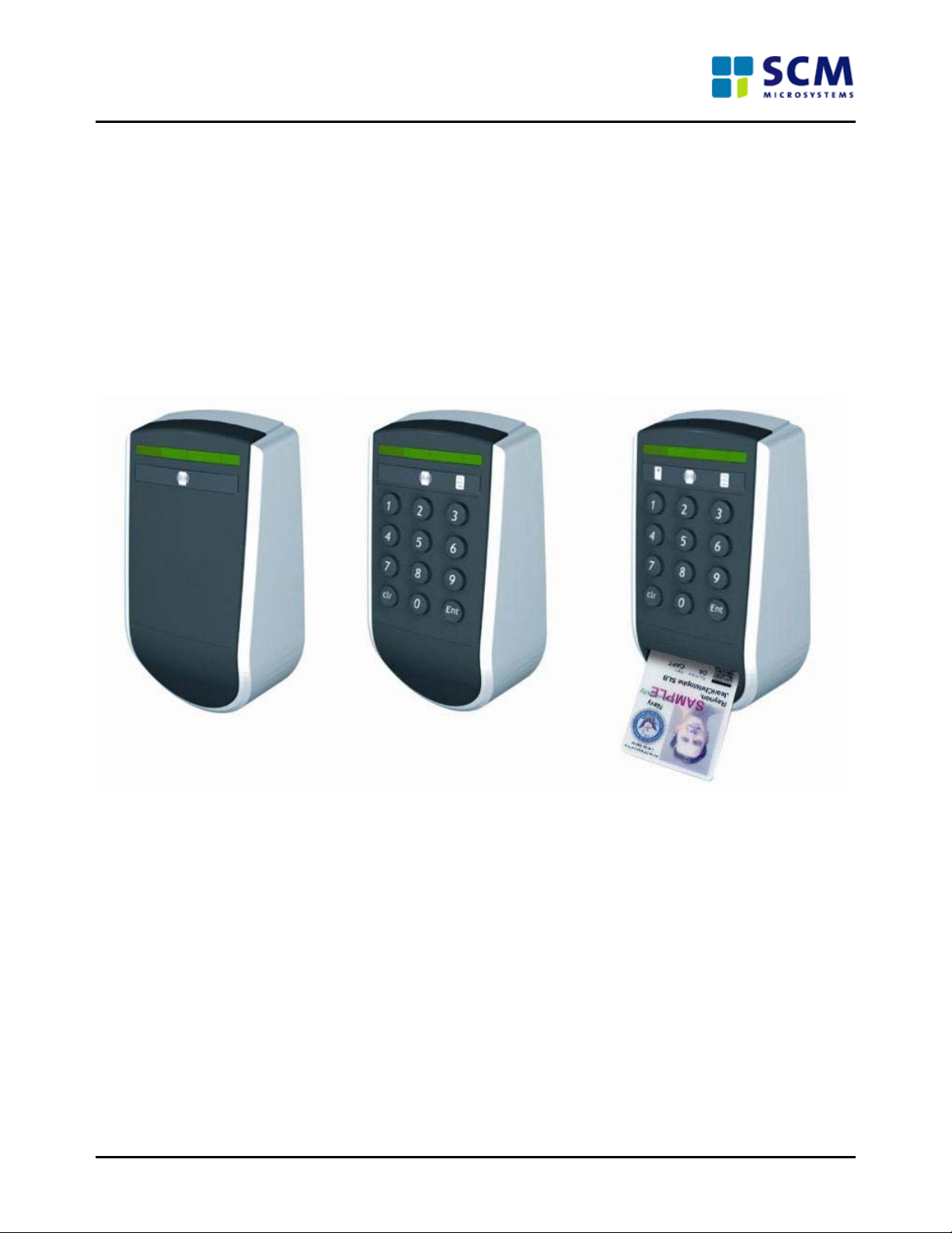
PAT 11x1
OEM Manual
PAT111 OEM Manual Page 1 of 9

Contents
1.0 Product Specification .................................................................................................................................3
1.1 Overview....................................................................................................................................................3
1.2 Specification .............................................................................................................................................. 3
2.0 Hardware details.......................................................................................................................................... 4
2.1 Product electrical ratings ...........................................................................................................................4
2.2 Clock Frequency........................................................................................................................................ 4
3.0 Software details...........................................................................................................................................4
3.1 Block diagram of the software architecture...............................................................................................4
3.2 Contact/SAM Card Parameters................................................................................................................. 5
3.3 Contactless card Parameters....................................................................................................................5
4.0 Similarities and Differences between PAT 11x1 readers........................................................................ 5
5.0 Duty Cycle....................................................................................................................................................6
6.0 DFU Application ..........................................................................................................................................6
6.0 Cable details ................................................................................................................................................6
7.0 Regulatory Compliance.............................................................................................................................. 7
7.1 Safety Regulations.....................................................................................................................................7
7.2 EMC Regulations.......................................................................................................................................7
7.3 FCC Compliance Statement (USA)...................................................................................................7
8.0 Photographs of Readers.............................................................................................................................9
PAT111 OEM Manual Page 2 of 9
1.0 Product Specification
1.1 Overview
The term PAT is an acronym for Physical Access Terminal .The PAT readers are designed and constructed to
provide a wide variety of configuration options. The readers support contact, contact less and pinpad
interface. The PAT 11x1 readers are based on ARM7 processor. The contactless interface is controlled by
Mifare IC controller. The readers are designed to support the following communication protocols to interface
with host PC/control panel.
Wiegand/Magnetic stripe
RS 485
Two separate slots reside at the back of the readers for the compatibility of the above mentioned
communication protocols. The LED and Buzzer in the readers constantly keep showing the u ser the status of
the readers during the operation. The PAT11x1 readers are designed for indoor use only.
1.2 Specification
Host Interface
SAM
Smartcard
interface
Smartcard
connector
Contactless
Keypad
Human Interface
Application
Dimensions
Power
• Wiegand/Magstripe (CLK/Data)
• RS485 (2 or 4 wires)
• 3 relay inputs to set reader state
• ISO 7816 1-3
• T=0, T=1 protocol support (5V card)
• Communication speed up to 344,086 bps
• ISO 7816 1-3
• T=0, T=1 protocol support (5V card)
• Communication speed up to 115,200 bps
• 8 contacts (ISO location)
• Landing contact, 500,000 insertions
• ISO 14443 Type A and B (13.56 MHz)
• Supports ISO 14443 part 1 to 4
• Operating distance: 1 inch for CAC
• Communicati on speed: 106 Kbps
• Internal 3DES for card aut hentication (DESFire)
• Standard telephone layout (0-9, Clear an d Enter)
• Robust hard cap, silicon keypad
• 1 LED beam (green and red) for access information
(granted and denied)
• 1 LED per type of media (contact, conta ctless and
keypad) to indicate the type of requested operation
• Buzzer for user acoustic feedba ck
• Full SDK (software development kit) available
• Field Secure firmware upgrade
• LWH 148x84x46 mm
• 12V DC- 200mA
PAT111 OEM Manual Page 3 of 9

2.0 Hardware details
2.1 Product electrical ratings
2.1.1 Voltage rating
+12V DC is taken from the control panel and regulated to +5V DC and +3.3V DC on the PAT11X1 PCBs.
Operating Voltage is 10V to 16V DC.
2.1.2 Current rating
Current consumption is 200 mA @12V for Device full operation. The current consumption during idle state is
160mA.
2.1.3 ESD and EFT
As per EN61000-4-2 4KV contacts and 8KV air discharge.
As per EN61000-4-4 the product can withstand up to 4KV EFT.
2.2 Clock Frequency
• ARM7 processor is running @ 45MHz, which is derived from an external 12 MHz crystal
• ICC clock @4-12M Hz
• Contactless reader's transmitter antenna and receiver circuit works @13.56MHz using MIFARE
RC531 controller.
• For RS485, the maximum sup ported baud rate is 115200 bps.
3.0 Software details
3.1 Block diagram of the software architecture
LEDs
Buzzer
GPIOs
Smartcard
Contactless
Application
Wiegand
Pinpad
Magstripe
RS485
Crypto
PAT111 OEM Manual Page 4 of 9

3.2 Contact/SAM Card Parameters
Some important smart card parameters, supported smart card types, maximum operable smart card
frequencies, operating voltages etc., are detailed in the tables below.
ICC Parameters Value/Description
Class A Smart Cards Supported
Class AB Smart Cards Supported
ISO-7816 compliant Yes
Smart card operating frequency 4MHz as a minimum (Up to 8MHz)
Maximum supported card baud-rate 344,086 bauds
3.3 Contactless card Parameters
Some important contactless card parameters, supported contact-less card types, maximum opera ble PICC
frequencies, operating voltages etc., are detailed in the tables below.
ICC Parameters Value/Description
Type A T=CL PICC Supported
Type B T=CL PICC Supported
ISO-14443 compliant Yes
PICC operating frequency 13.56MHz
Maximum supported card baud-rate 424Kbps
4.0 Similarities and Differences between PAT 11x1 readers
Features PAT 1111 PAT 1121 PAT 1141
The application is
The application is
Software
Wiegand Yes Yes Yes
Magstripe Yes Yes Yes
RS485 Yes Yes Yes
Optional SAM Yes Yes Yes
Protocol T=CL T=CL T=0, T=1,T=CL
ISO14443 Yes Yes Yes
ISO7816 No No Yes
Relay Inputs 3 3 3
LED per
media type
configured for
contactless cards only.
1 2 3
configured for both
contactless and pinpad.
The reader will wait for
the pinpad entry first.
The application is configured for
contactless, pinpad and
smartcard. The reader will wait
for either the pinpad entry or
the smartcard whichever is first.
Dimension LWH 148 x 84 x 46 mm LWH 148 x 84 x 46 mm LWH 148 x 84 x 46 mm
PAT111 OEM Manual Page 5 of 9

5.0 Duty Cycle
The product is designed to work 365 days 24 hours. The RF is always ON for PAT1111 reader. For PAT1 121
reader, RF will be activated only when the user enters the correct PIN number. For PAT1141, the reader will
wait for either the pin pad entry or the smartcard whichever is first.
6.0 DFU Application
DFU is the acronym for Device Firmware Upgrade. The DFU application is used for programming the onboard
flash in the PAT readers through RS232 interface and allows seamless reconfiguration of the reader and
prevents obsolescence. A RS485 to RS232 converter has to be used to connect the reader to the host PC.
The application is capable of running under the following operating systems.
Operating System Support
WIN98 Yes
WINME Yes
WIN2000 Yes
WINXP Yes
6.0 Cable details
For Wiegand/Magstripe interface:
10 core 22 AWG foil shielded cable should be used. A maximum cable length of 150 meters is supported. At
the power supply end, GND should be connected to the shield of the cable.
For RS485 interface:
8 core 22 AWG foil shielded cable should be used. A maximum cable length of 4000 feet is supported. At the
power supply end, GND should be connected to the shield of the cable.
PAT111 OEM Manual Page 6 of 9

7.0 Regulatory Compliance
This section describes the product's compliance with U.S. and international safety and electro magnetic
compatibility (EMC) regulations.
7.1 Safety Regulations
The safety regulations to which the product complies with when correctly installed in a compatible host
system are:
Regulation Title
UL 294 US Safety of Information Technology Equipment
7.2 EMC Regulations
Regulation Title
FCC (Class B) Title 47 of the Code of Federal Regulations, Parts 2
and 15, Subpart C,Radio Frequency Devices. (USA)
VCCI:1997 Class
B ITE
7.3 FCC Compliance Statement (USA)
Product Type: Contact / contactless smart card reader.
Product Name: PACT- ARM7
This device complies with Part 15 of the FCC Rules. Operation is subject to the following two conditions:
(1) This device may not cause harmful interference and (2) this device must accept any interference received,
including interference that may cause undesired operation.
This equipment has been tested and found to comply with the limits for a Class B digital device, pursuant to
Part 15 Sub part C of the FCC Rules. These limits are designed to provide reasonable protection against
harmful interference in a residential environment. This equipment generates, uses, and can radiate radio
frequency energy and, if not installed and used in accordance with the instructions, may cause harmful
interference to radio communications. However, there is no guarantee that interference will not occur in a
particular installation. If this equipment does cause harmful interference to radio or television reception, which
can be determined by turning the equipment off and on, the user is encouraged to try to correct the
interference by one or more of the following measures:
Reorient or relocate the receiving antenna. Increase the separation between the equipment and the receiver.
Connect the equipment to a different electrical branch circuit from that to which the receiver is connected.
Consult the dealer or an experienced radio/TV technician for help. Any changes o r modification s to the
equipment not expressly approved by SCM could void the user’s authority to operate the equipment.
PAT111 OEM Manual Page 7 of 9

7.4 Product Ecology Statements
The following information is provided to address worldwide product ecology concerns and regulations.
7.4.1 Disposal Considerations
This product contains the following materials that may be regulated upon disposal:
lead solder on the printed wiring board assembly.
7.4.2 Recycling Considerations
SCM encourages its customers to recycle its products and their co mponents (e.g., batteries, circuit boards,
plastic enclosures, etc.) whenever possible. In the U.S., a list of recyclers in your area can be found at:
http://www.eiae.org/
In the absence of a viable recycling option, products and their components must be disposed of in
accordance with all applicable local environmental regulations.
PAT111 OEM Manual Page 8 of 9

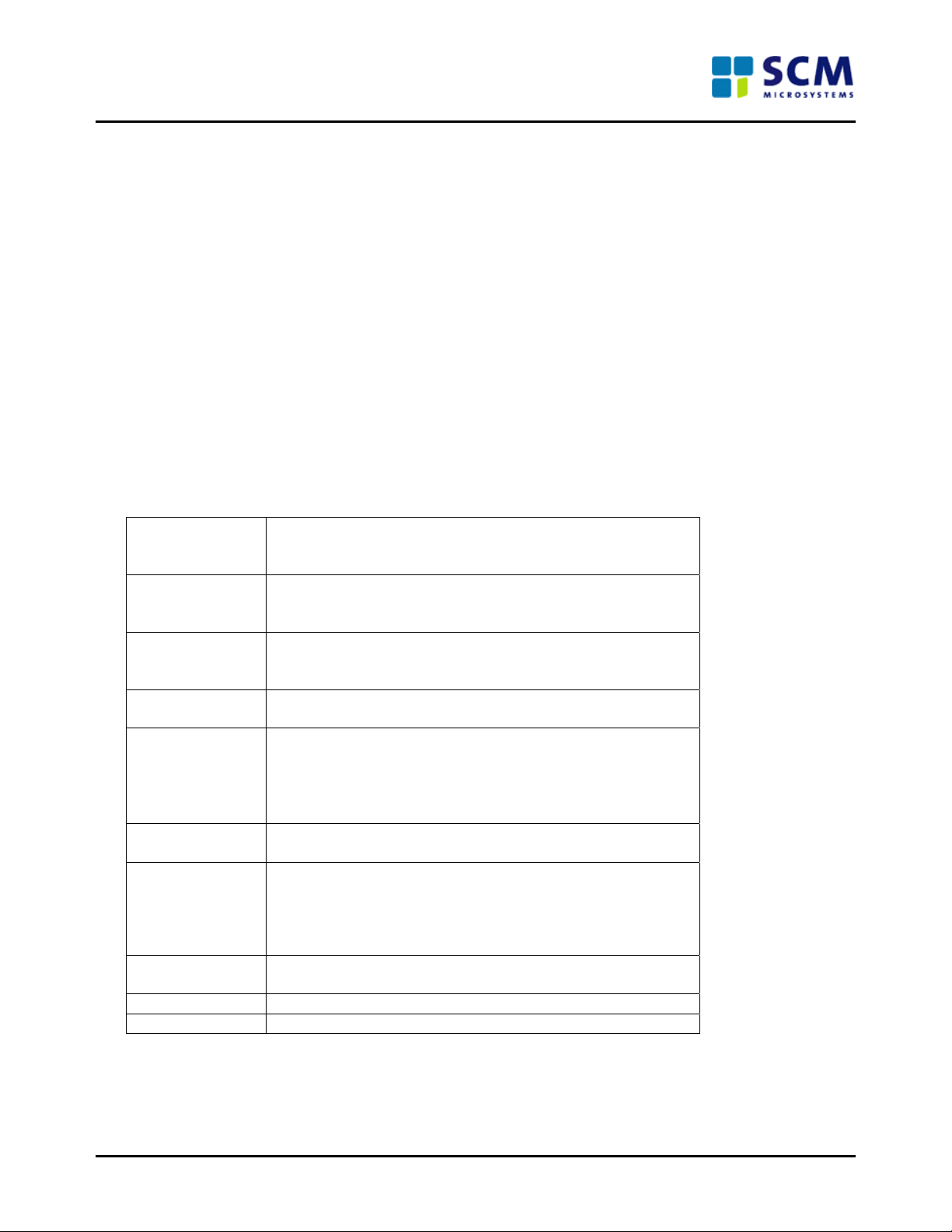
8.0 Photographs of Readers
Front view
Contactless LED
Access Granted/Denied
Indication LED
Pin Pad LED
Contact LED
Pin Pad Contact card slot
PAT 1111 PAT 1121 PAT 1141
Rear view (The rear view appears similar for PAT1111, PAT1121 and PAT1141 readers)
10 pin terminal block for
Wiegand/Magstripe
8 pin terminal block for
RS485
RS485 DIP switch
End of the Document
PAT111 OEM Manual Page 9 of 9
 Loading...