

Page 1

I
SC
0
SC
0
User Manual
Version 1.00 2014.01.
-4
1
Page 2

COPYRIGHT
The Information in this document is subject to change without notice. IDT Inc
license agreement and is protected by international copyright laws. You may copy it
out in the license agreement
ISC
101/201/301/401 is a registered trademark of IDT Inc
Manual COPYRIGHT (C) 2004 IDT Inc. All rights reserved.
.
reserves the right to revise this document and to make changes from time to time in
the content hereof without obligation to notify any person or persons of such
revisions or changes. The software described in this document is supplied under a
only for the purpose of backup and use it only as described in the License
agreement. Any implied warranties including any warranties of merchantability or
fitness for a particular purpose are limited to the terms of the express warranties set
.
Program COPYRIGHT (C) 2003-2004 IDT Inc. All rights reserved.
Trademarks
BioScan is a registered trademark of IDT Inc.
Other products, trademarks or registered trademarks are the property of their
respective owners.
.
Page 3

WARNING!
THIS DEVICE COMPLIES WITH PART 15 OF THE FCC RULES. OPERATION
CAUSE UNDESIRED OPERATION
MODIFICATIONS COULD VOID THE USER S AUTHORITY TO OPERATE THE
• 15.19:
IS SUBJECT TO THE FOLLOWING TWO CONDITIONS: (1) THIS DEVICE MAY NOT
CAUSE HARMFUL INTERFERENCE, AND (2) THIS DEVICE MUST
ACCEPT ANY INTERFERENCE RECEIVED, INCLUDING INTERFERENCE THAT MAY
• 15.21:
The user manual for an intentional or unintentional radiator shall caution the user that
changes or modifications not expressly approved by the party responsible for compliance
could void the user’s authority to operate the equipment.
.
• NOTE: THE GRANTEE IS NOT RESPONSIBLE FOR ANY CHANGES OR
MODIFICATIONS NOT
• EXPRESSLY APPROVED BY THE PARTY RESPONSIBLE FOR COMPLIANCE. SUCH
’
EQUIPMENT.
Page 4

WARRANTY
period, the warranty period for a Product shall commence upon the date stated in the Product Warranty
IDTi
yg
EXCEPT THOSE INCLUDED IN THE PRODUCT WARRANTY
IDTi
DISCLAIMS ALL OTHER
Limited Warranty:
All Products sold to Dealer hereunder shall be subject to IDTi standard warranty for
the Product included with the Product by IDTi (“Product Warranty”). The Product Warranty shall be
extended to end user purchasers of the Products from Dealer who purchases such Products within twelve
(12) months of the date the Products are shipped to Dealer. Provided within the aforementioned time
.
Dealer shall not extend any warranty regarding the Products other than IDTi then standard warranty. The
limited warranty statement included in the Product Warranty is the exclusive statement of the controlling
terms and conditions of the limited warranties on the Products. Nothing in this Agreement or any other
written document or any oral communications with Dealer or other parties may alter the terms and
conditions of the Product Warranty.
to time, however; no change in limited warranties will affect Product orders already accepted by IDTi.
Dealer agrees to only pass on to Dealer’s end-users IDTi limited warranties and Dealer will be liable for
any greater warranty that Dealer purposely or inadvertently transfers to end-users. Dealer will indemnify,
defend and hold IDTi harmless for any damages or other costs that arise because of Dealer’s failure to
properly inform Dealer’s end-users of current limited warranties.
may, in its sole discretion, revise its limited warranties from time
Warranty Disclaimer: IDTi MAKES NO EXPRESS OR IMPLIED WARRANTIES FOR THE PRODUCTS
.
WARRANTIES, EXPRESS OR IMPLIED, INCLUDING, WITHOUT LIMITATION, IMPLIED
WARRANTIES OF MERCHANTABILITY AND FITNESS FOR A PARTICULAR PURPOSE.
Page 5

Table of Contents
CHAPTER 3
ISC-401 ………………….……………………..5
CHAPTER 1 …………………………………….9
ENROLL USER, EDIT USER
CHAPTER 2 …………………………………….14
SYSTEM SETUP & EDIT
…………………………………….20
INSTALLATION GUIDE
Page 6

ISC-401 (Layout)
Down
r
Speaker
LCD
Display
Function Key
Camera
Proximity Reader
LED Indicator
Program / Scroll Up / Space
Scroll
Backspace / Detail
View
Clea
Escape
Enter
Page 7
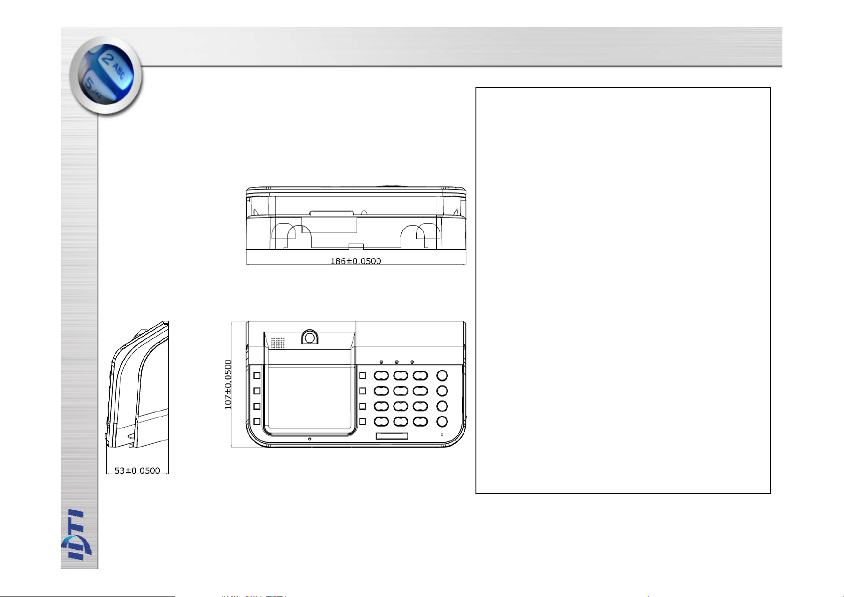
ISC-401 (SPECIFICATION)
SC
►
Log Data : 1,000,000 (
Upto
2,000,000)
U
254
SIZE :
►
C
232
TCP/IP
I
-401 Specification
► USER : 131,072
Log Image : 10,000 Upto 20,000
► Time Zone : Controller:1024,
Reader Per 1024
► Holiday : 365
►
ser Level :
► User Group : 1024
► FAR = 0.00008 %
► FRR = 0.09 %
► CPU :
ARM11 32bit,
ARM 32-bit Cortex™-M3 CPU
► POWER : 12V DC 1A
►
► Temperature : -10℃~50℃
► Humidity : 10%~90%
► RF Card : ~10 cm
Option RS-422(1.2 Km),
► IN/OUT : 4 In / 2 Out
► Material : ABS (Polycarbonate)
- H107 X W186 X D53mm
ommunication : RS-
,
,
Page 8
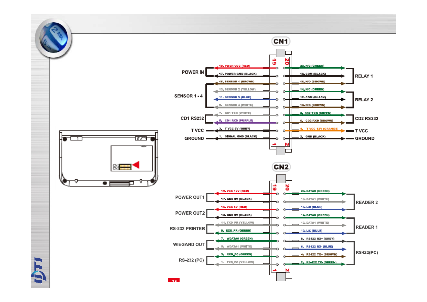
Connector Layout
Page 9
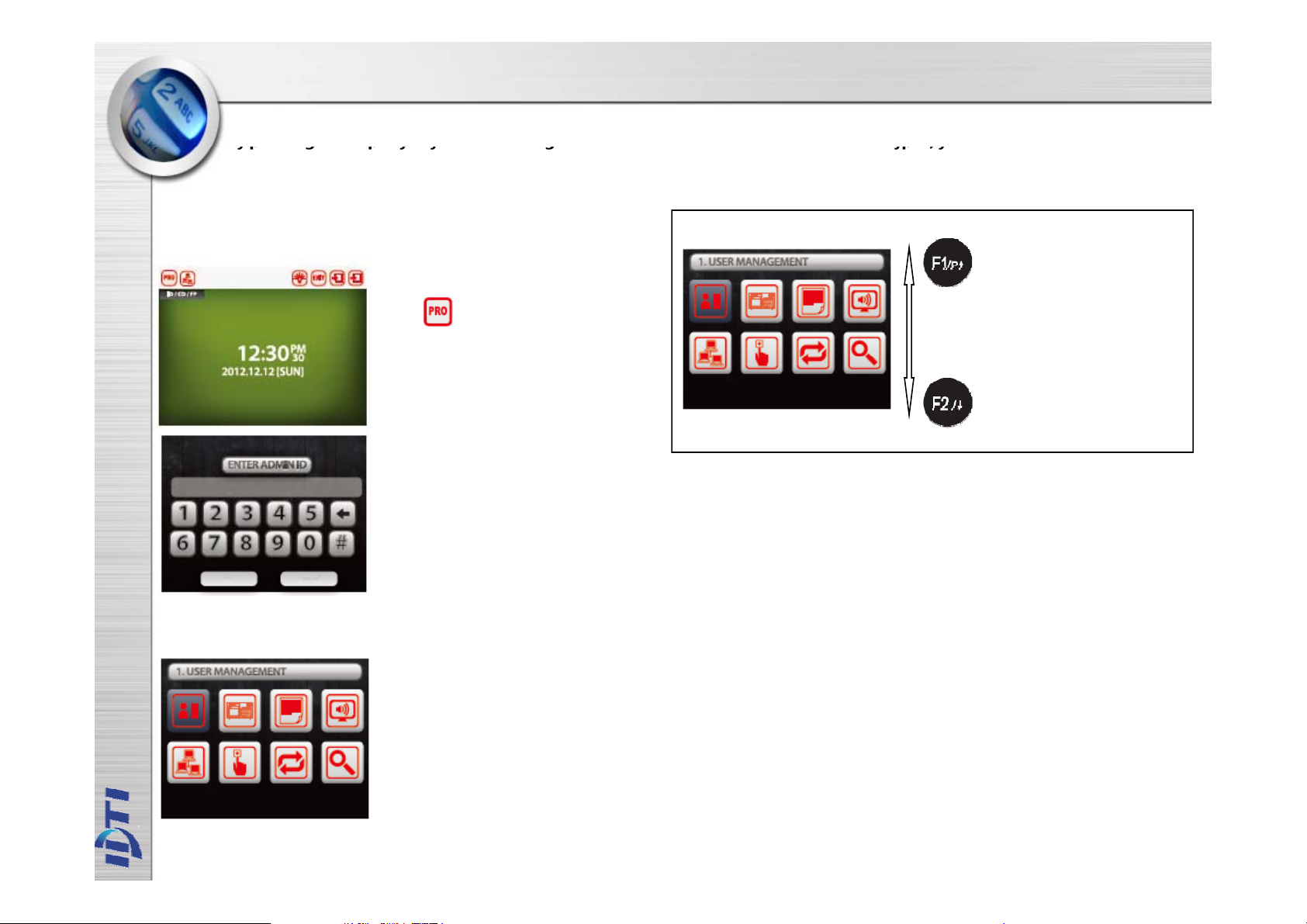
ENTERING THE SYSTEM MENU
y p
yp g p y y g yp ,y
When the reader is powered on with no fingerprint templates enrolled in the unit, anyone can enter the system menu
b
ressing the F1/p key. If you are enrolling the first administrator card via the reader's keypad, you must first
determine the 1~16 digit PIN that the administrator will use. Once this PIN is determined, the administrator must be
present to enroll their card into the reader. Note that this operation is not valid if there are administrator card in the
reader.
If Administrator has been enrolled
1. Press F1/P key to enter system mode.
Press to enter system mode
2. Key in administrator ID followed by
the # key Input fingerprint or Card
3. Present either finger or card which ever
administrator has been enrolled with. For
now we will use the fingerprint.
4. Now you're into system mode.
Press F1 key to scroll up the main menu
Press F2 key to scroll down the main
menu
If no Administrator has been enrolled
Main Menu List
1. ‘F1/P’ or ‘F2’ Key ‘#’ Key.
or Touch Screen
1.Press F1/P key to enter system mode
2. Now you're into system mode.
Press F1 key to scroll up the main menu
Press F2 key to scroll down the main
menu
Page 10

CHAPTER 1
2
USER MANAGEMENT
1. Enroll User ………………...……………………………………10
2. Edit User ………….…………………….…………….……..…..11
3. Delete User ……..………………….…………………………...12
4. Delete All User …….…………………..…………….………...1
5. View User ………………..…………………………..………….13
Page 11

User Enroll
g
y
gy y p pp gy
7
administrative functions.
This command is used to add typical fingerprint only users to the reader so that they will be able to gain entry to the
location
sequence performs this action:
uarded by the reader. The system has an option to enroll either 2 or 4 templates per user. The following ke
1. Press F1/P key to enter system mode.
Press to enter system mode
2. Press ‘#’ Key USER MEMAGEMENT
Select.
3. Press F1/P(UP) or F2 Key Add-menu
Select or Press LCD Icon
. Present first finger to the scanner. Remove
the fingerprint when the red light turns off.
You can either enroll same fingerprint or
different fingerprint after the first. Repeat this
process until the last fingerprint
8. Enroll completed. Press the # key to
continue enrolling another user fingerprint
or press any others to exit off the sub-menu
4. Key in user ID from 1 to 16 digits as
shown in next figure
5. Key in user ID followed by the # key
6. System has an option to enroll 1~4
fingerprint templates per each user. For
now we will select number 1~4 key by
enrolling 1~4 templates
Enroll Fingerprint
Enroll Card
NOTE :
There are 2 levels of administration,
1. USER (Level 1) - Corresponds to an ordinary user. They may verify, but are not
allowed to access any
2. ADMIN (Level 4) - This is an system administrator level and has full rights to
configure the reader.
Page 12

Edit User
7
This command is used to edit existing users ID by accessing the user ID. When editing, Administrators have the
ability to make changes to user ID only in this menu.
1. Press F1/P key to enter system mode.
Press to enter system mode
2. Press ‘#’ Key USER MEMAGEMENT
Select.
3. Press F1/P(UP) or F2 Key Edit-menu
Select or Press LCD Icon
. Present first finger to the scanner. Remove
the fingerprint when the red light turns off.
You can either enroll same fingerprint or
different fingerprint after the first. Repeat this
process until the last fingerprint
8. Enroll completed. Press the # key to
continue enrolling another user fingerprint
or press any others to exit off the sub-menu
4. Key in user ID from 1 to 16 digits as
shown in next figure
5. Key in user ID followed by the # key
6. System has an option to enroll 1~4
fingerprint templates per each user. For
now we will select number 1~4 key by
enrolling 1~4 templates
Page 13

Delete User
via the reader. Any fingerprint template can be removed
Select
LCD
4. K
ey in user ID from 1 to 16 digits as
Deleting a fingerprint template from a reader will prevent
that template from being granted access to the location
from a fingerprint reader, including administrative and the
last remaining fingerprint template on the reader.
Templates can be deleted by a single user or all users
including administrative templates.
1. Press F1/P key to enter system mode.
Press to enter system mode
2. Press ‘#’ KeyUSER MEMAGEMENT
Select.
Deleting a all user will erase all template from a reader,
including administrative and the last remaining
fingerprint
template on the reader.
1. Press F1/P key to enter system mode.
Press to enter system mode
2. Press ‘#’ Key USER MEMAGEMENT
Select.
3. Press F1/P(UP) or F2 Key Delete All-menu
Select or Press LCD Icon
3. Press F1/P(UP) or F2 Key Delete-menu
or Press
shown in next figure
5. Key in user ID followed by the # key
Icon
4. Press ‘OK’ or Press the # key to
confirm delete all
Press any other key to cancel
Page 14

View User
the system, or it can be a list of the individual users that are physically enrolled on any individual fingerprint
User Name
At any time, you can view a list of all users of the system. The list can be an overall enrollment list of all users in
reader.
USER LEVELFingerprint Count
1. Press F1/P key to enter system mode.
Press to enter system mode
Memory Index
2. Press ‘#’ Key USER MEMAGEMENT
Select.
3. Press F1/P(UP) or F2 Key View-menu
Select or Press LCD Icon
4. View Enrolled User / Total User.
5. Press F1(UP) or F2(DN) Key.
User Id
Card Number
Page 15

CHAPTER 2
8
DEVICE SETTING
Terminal Configuration …..…………….…………..………..…15
Terminal Log ………………………………………..…………......16
AUDIO/VIDEO ……………………………………………..….…....17
Network …………………………………...…………..…….……...1
INPUT / OUTPUT ……...……………………………….....……..19
Page 16

System setup
1.
LOCAL ADDRESS : 132
p
2.Press # Key
TERMINAL Select
p
ID&FINGER
()
y
ID&CARd
OPTION
Access Option Setup
DURESS
ADDRESS
TIME
SYSTEM MODE
RELOCK TIME
SYSTEM RESET
OPTION
LANGUAGE
1. Press F1/P key to enter system mode.
Press to enter system mode
‘
’
3. Press F1/P(UP) orF2 Key or Press
Touch LCD Menu Select
ADDRESS
~
2. SYSTEM ADDRESS : 0~65535
TIME
System Time Setup
SYSTEM MODE
Device Access Mode Setu
CARD / FINGER
CARD/ ID&FINGER
ID&CARD&FINGER
ID / CARD/ FINGER
FINGER(ID&FINGER)
CARD&FINGER
ID&FINGER ID&CARD
ID&FINGER CARD&FINGER
ID&CARD CARD&FINGER
ID / CARD
CARD
OPEN
CLOSE
SYSTEM RESET
RELOCK TIME
Lock Time Setup
1~99 Sec
:
ANTIPASS BACK
KEY SECURE
LOCK DOWN
FUNCTION KEY
DAY DISPLAY TYPE
LANGUAGE : Display Language Setup
Page 17

Log
2.Press # Key
SYSTEM LOG Select
()
y
PHOTO FORMAT
LOG VIEW
INDEX CHANGE
LOG FORMAT
PHOTO FORMAT
1. Press F1/P key to enter system mode.
Press to enter system mode
‘
’
3. Press F1/P(UP) orF2 Key or Press
Touch LCD Menu Select
LOG VIEW
INDEX CHANGE
LOG FORMAT
Page 18

AUDIO/VIDEO
CAMETA
2.Press # Key
AUDIO/VIDEO Select
()
y
EXTERNAL2
CAMETA
PRINTER
TOUCH SCREEN
INFRARED
SERIAL-SPEED
SPKVOLUME
THEMES
1. Press F1/P key to enter system mode.
Press to enter system mode
‘
’
3. Press F1/P(UP) orF2 Key or Press
Touch LCD Menu Select
CAMERA ENABLE/DISABLE
EVENT MODE ENABLE/DISABLE
BRIGHTNESS
ANGLE
FRAME RETE
DENIED SAVE
PRINTER
TOUCH SCREEN
TOUCH Calibration
INFRARED
INFRARED ENABLE/DISABLE
FINGER MODE
DETECT LEVEL
SERIAL-SPEED
PC
PRINTER
EXTERNAL 1
SPKVOLUME
THEMES
Page 19

Network
NET VIEW
and if set as Client then the software must be set as
2.Press # Key
NETWORK Select
()
y
4: Manual selection of 100 BASE
FDX
NET VIEW
NET SETUP
NET SPEED
CALL SERVER
1. Press F1/P key to enter system mode.
Press to enter system mode
‘
’
3. Press F1/P(UP) orF2 Key or Press
Touch LCD Menu Select
NET SETUP
System can operate either as Server or Client. If set
as Server then the software must be set as Client
Server.
Static/DHCP
IP Address
Gateway
Subnet mask
Port
Server IP Address
Server Port
NET SPEED
0: Auto-negotiation enable with all capabilities
1: Auto-negotiation with 100 BASE-TX FDX/HDX ability
2: Auto-negotiation with 10 BASE-T FDX/HDX ability
3: REV(0-Auto-negotiation enable with all capabilities)
-TX
5: Manual selection of 100 BASE-TX HDX
6: Manual selection of 10 BASE-T FDX
7: Manual selection of 10 BASE-T HDX
CALL SERVER
intercom PC server Setup.
Page 20

INPUT / OUTPUT
yp yp( ), gg gg y ,
pg g p y g
3: HID Full Bi
26bit Card
9: Mifare
64bit UID
ALARM
1. Press F1/P key to enter system mode.
Press to enter system mode
2. Press ‘#’ Key INPUT/OUTPUT
Select
SENSOR
RELAY
CARD TYPE
WIEGAND TIME
WIGAND TYPE
SENSOR
These are the senor inputs found in device control panel that control external devices. There are 4
sensor inputs in device and all of them can be programmed to handle different types of external
sensors from the system menu.
RELAY
The relay output is Normally Open (N.O.), and toggles shorted when triggered by an event, such as
an authentication or ID failure. The relay can be used to send power to switched items like electric
door strikes, door handles, magnetic hold locks. The alarm can be used to send signals to a alarm
panel, controllers or indicators.
ALARM
There are six sensor inputs and 2 relays outputs in the system. Either one or two relays are used for
the lock, depending on the configuration, and the spare relays can be used for annunciating alarms
or other form of control. There is no programming function for alarms what you program is what
happens when a specific alarm occurs. There are two things that can happen as a result of an alarm:
an alarm may result in a message to the speaker (Buzzer).
an alarm may also cause a relay to come on (Relay).
Device has an output to activate a sounder but also equipped with relays that can be controlled from
a command station, by some type of system activity. These sensor inputs & relays can allow you to
perform many functions such as motion sensor or as a means of interfacing with a home automation
system. Only the internal sensors will be activated unless other sensors are connected and
configured in Sensor Setup. Relay must be connected to use the alarm. Refer to Relay Connector.
CARD TYPE
1: EM Standard 26bit Card
2: HID Standard 26bit Card
nary
4: HID IDTi 34bit Card
5: Mifare 32bit UID Card
6: Mifare 34bit iClass
7: Mifare 34bit iClass2
8: Mifare 32bit UID 2
WIEGAND TIME
Wiegand data output time setup
WIGAND TYPE
1: USER ID
2: USER CARD
3: CARD READER DIRECT OUTPUT
3. Press F1/P(UP) or F2 Key or Press
Touch LCD Menu Select
Page 21

CHAPTER 3
4
RS
-
422 C
28
INSTALL
Connector Layout …..………………………...….…………..…21
Power Connection ……………………….……..……….….........22
Sensor Connection ………………………………..………..…....23
Relay (Lock) Connection …………………….…...…...…...….2
RRE Connection ………….………………………..….....……..25
Card Reader Connection ………………………….…………..26
RS-232 Connection ……………………..………………………29
Install Diagram ……………………………..……….…….…....30
onnection …………………………..……….…………
Page 22

CONNECTOR LAYOUT
Page 23

POWER CONNECTOR
Page 24

SENSOR CONNECTOR
Page 25

RELAY (LOCK) CONNECTOR
Page 26

RRE CONNECTOR
Page 27

Card Reader 1 Connection
Page 28

Card Reader 2 Connection
Page 29

RS422 NETWORK DIAGRAM
Page 30

RS-232 CONNECTOR
Page 31

INSTALLATION DIAGRAM
 Loading...