


IDTi
IDTi
Gabool Great Valley Bldg. A, 8th Floor
Gasan Dong Geumcheon Gu 60-5
Seoul 153-801, Korea
Tel: 82-2-3397-7991
BSC-101
USER MANUAL
V.4.0
WW W.IDTI.CO.KR
PublICaTIOn nO. 33-10038-001-G

Copyright
BSC-101 V.4.0 Manual
Manual COPYRIGHT (C) 2004 IDT Inc. All rights reserved.
The Information in this document is subject to change without notice. IDT Inc.
reserves the right to revise this document and to make changes from time to time in
the content hereof without obligation to notify any person or persons of such
revisions or changes. The software described in this document is supplied under a
license agreement and is protected by international copyright laws. You may copy it
only for the purpose of backup and use it only as described in the License
agreement. Any implied warranties including any warranties of merchantability or
fitness for a particular purpose are limited to the terms of the express warranties set
out in the license agreement.
Program COPYRIGHT (C) 2003-2004 IDT Inc. All rights reserved.
Trademarks
BioScan is a registered trademark of IDT Inc.
BSC-101/201/301/401 is a registered trademark of IDT Inc.
Other products, trademarks or registered trademarks are the property of their
respective owners.

WARNING!
15.19:
THIS DEVICE COMPLIES WITH PART 15 OF THE FCC RULES. OPERATION
IS SUBJECT TO THE FOLLOWING TWO CONDITIONS: (1) THIS DEVICE MAY NOT
CAUSE HARMFUL INTERFERENCE, AND (2) THIS DEVICE MUST
ACCEPT ANY INTERFERENCE RECEIVED, INCLUDING INTERFERENCE THAT
MAY CAUSE UNDESIRED OPERATION.
15.21:
The user manual for an intentional or unintentional radiator shall caution the user that
changes or modifications not expressly approved by the party responsible for compliance
could void the user’s authority to operate the equipment.
NOTE: THE GRANTEE IS NOT RESPONSIBLE FOR ANY CHANGES OR
MODIFICATIONS NOT
EXPRESSLY APPROVED BY THE PARTY RESPONSIBLE FOR COMPLIANCE. SUCH
MODIFICATIONS COULD VOID THE USER’S AUTHORITY TO OPERATE THE
EQUIPMENT.

Limited Warranty
All Products sold to Dealer hereunder shall be subject to IDTi standard warranty
for the Product included with the Product by IDTi (“Product Warranty”). The
Product Warranty shall be extended to end user purchasers of the Products from
Dealer who purchases such Products within twelve (12) months of the date the
Products are shipped to Dealer. Provided within the aforementioned time period,
the warranty period for a Product shall commence upon the date stated in the
Product Warranty. Dealer shall not extend any warranty regarding the Products
other than IDTi then standard warranty. The limited warranty statement included
in the Product Warranty is the exclusive statement of the controlling terms and
conditions of the limited warranties on the Products. Nothing in this Agreement or
any other written document or any oral communications with Dealer or other
parties may alter the terms and conditions of the Product Warranty. IDTi may, in
its sole discretion, revise its limited warranties from time to time, however; no
change in limited warranties will affect Product orders already accepted by IDTi.
Dealer agrees to only pass on to Dealer’s end-users IDTi limited warranties and
Dealer will be liable for any greater warranty that Dealer purposely or
inadvertently transfers to end-users. Dealer will indemnify, defend and hold IDTi
harmless for any damages or other costs that arise because of Dealer’s failure to
properly inform Dealer’s end-users of current limited warranties.
Warranty Disclaimer: IDTi MAKES NO EXPRESS OR IMPLIED WARRANTIES
FOR THE PRODUCTS EXCEPT THOSE INCLUDED IN THE PRODUCT
WARRANTY. IDTi DISCLAIMS ALL OTHER WARRANTIES, EXPRESS OR
IMPLIED, INCLUDING, WITHOUT LIMITATION, IMPLIED WARRANTIES OF
MERCHANTABILITY AND FITNESS FOR A PARTICULAR PURPOSE.

BSC-101 V.4 Operations ManualI
Table of Contents
Foreword 0
Part I Navigating the System
Part II Using the Fingerprint Scanner
Part III Quick Start
................................................................................................................................... 71 Pre-Installation Checklist
................................................................................................................................... 72 Entering the System Menu
................................................................................................................................... 7If Administrator has been enrolled
................................................................................................................................... 8If no Administrator has been enrolled
................................................................................................................................... 83 Operating System
................................................................................................................................... 8Operating with User PIN
................................................................................................................................... 8Operating with User CARD
................................................................................................................................... 8Operating with User PIN & CARD
2
4
7
................................................................................................................................... 9Operating with User FINGERPRINT
................................................................................................................................... 9Operating with User PIN & FINGERPRINT
................................................................................................................................... 9Operating with User CARD & FINGERPRINT
................................................................................................................................... 9Operating with User PIN & CARD & FINGERPRINT
................................................................................................................................... 104 Operating the System with Funtion Key
................................................................................................................................... 10Operating Function Key in PIN
................................................................................................................................... 10Operating Function Key in CARD
................................................................................................................................... 10Operating Function Key in PIN and CARD
................................................................................................................................... 11Operating Function key in FINGERPRINT
................................................................................................................................... 11Operating Function key in PIN & FINGERPRINT
© 2012 IDTi

................................................................................................................................... 11Operating Function key in CARD & FINGERPRINT
................................................................................................................................... 12Operating Function key in PIN & CARD & FINGERPRINT
IIContents
Part IV SYSTEM MENU 1 - ENROLL USER
................................................................................................................................... 141 1. Enroll Fingerprint User
................................................................................................................................... 152 2. Enroll Card User
................................................................................................................................... 153 3. Enroll Card and Fingerprint User
................................................................................................................................... 164 4. Enroll Block of Card User
................................................................................................................................... 175 5. Enroll Block of Card User 2
Part V SYSTEM MENU 2 - EDIT USER
................................................................................................................................... 201 1. Edit User ID
................................................................................................................................... 202 2. Edit User Fingerprint
................................................................................................................................... 203 3. Edit User Card
................................................................................................................................... 214 4. Edit User Level
14
20
................................................................................................................................... 215 5. Edit User Name
................................................................................................................................... 236 6. User Antipass
................................................................................................................................... 237 7. Option (ID)
................................................................................................................................... 248 8. User Two Man
................................................................................................................................... 249 9. Restriction TIme
................................................................................................................................... 2510 10. Restriction Count
................................................................................................................................... 2511 11. Restriction Type
................................................................................................................................... 2612 12. User Password
Part VI SYSTEM MENU 3 - VIEW USER
................................................................................................................................... 281 1. User List
28
© 2012 IDTi
II

BSC-101 V.4 Operations ManualIII
................................................................................................................................... 292 2. Events
................................................................................................................................... 293 3. Firmware
Part VII SYSTEM MENU 4 - DELETE USER
................................................................................................................................... 321 1. Delete Single User
................................................................................................................................... 322 2. Delete All User
Part VIII SYSTEM MENU 5 - SYSTEM SETUP
................................................................................................................................... 341 1.Time
................................................................................................................................... 342 2. Operating Mode
................................................................................................................................... 35Setting Operating Mode
................................................................................................................................... 353 3. Re-Lock Time
................................................................................................................................... 364 4. Address
................................................................................................................................... 365 5. Communication Password
................................................................................................................................... 366 6. Site Code
32
34
................................................................................................................................... 377 7. System Reset
................................................................................................................................... 378 8. Event Reset
................................................................................................................................... 389 9. Com. Speed
................................................................................................................................... 3910 10. Door Relay
................................................................................................................................... 3911 11. Two Man
................................................................................................................................... 3912 12. Anti Pass Back
................................................................................................................................... 4013 13. Duress
................................................................................................................................... 4014 14. Date Format
................................................................................................................................... 4115 15. Custom Display
................................................................................................................................... 4216 16. LCD Light
© 2012 IDTi

IVContents
................................................................................................................................... 4317 17. Conceal PIN
................................................................................................................................... 4418 18. Lockdown
................................................................................................................................... 4419 19. Attendance
................................................................................................................................... 4520 20. Network Setup
................................................................................................................................... 45Device IP Address Setup
................................................................................................................................... 45Manual Server Mode
................................................................................................................................... 46Manual Client Mode
Host PC IP Address Setup
................................................................................................................................... 48
................................................................................................................................... 48DHCP Mode
DHCP Server Mode
................................................................................................................................... 48
DHCP Client Mode
................................................................................................................................... 49
................................................................................................................................... 49View IP Configuration
................................................................................................................................... 4921 21. Remove Event
................................................................................................................................... 5022 22. Wiegand Type
................................................................................................................................... 5023 23. Wiegand Time
................................................................................................................................... 5024 24. Display COM
................................................................................................................................... 5025 25. Lanaguage
................................................................................................................................... 5126 26. System Option
................................................................................................................................... 511. Request Event
................................................................................................................................... 512. Serial Port
................................................................................................................................... 523. Printer
© 2012 IDTi
................................................................................................................................... 524. GSM Mode
................................................................................................................................... 525. User ID Format
IV

BSC-101 V.4 Operations ManualV
................................................................................................................................... 526. Program F1 * 4
................................................................................................................................... 537. Beep Setup
................................................................................................................................... 538. Validity Setup
................................................................................................................................... 539. Check In/Out
................................................................................................................................... 5327 27. Authentication Server
................................................................................................................................... 5428 28. Ping Test
Part IX SYSTEM MENU 6 - SENSOR SETUP
................................................................................................................................... 561 1. Input Type
................................................................................................................................... 562 2. Function
................................................................................................................................... 573 3. Bell Active
Part X SYSTEM MENU 7 - ALARM SETUP
................................................................................................................................... 591 Alarm Setup
................................................................................................................................... 612 Connecting External Lamp & Alarm
................................................................................................................................... 61Alarm Connection Diagram
Part XI SYSTEM MENU 8 - SCANNER SETUP
................................................................................................................................... 631 1. Re-Scan
................................................................................................................................... 632 2. Level
56
59
63
................................................................................................................................... 633 3. Lighting Condition
................................................................................................................................... 634 4. Enroll Mode
................................................................................................................................... 645 5. Identification Speed
................................................................................................................................... 646 6. Finger Detect
Part XII INSTALLATION GUIDE
................................................................................................................................... 661 Connector Layout
66
© 2012 IDTi

VIContents
................................................................................................................................... 672 Sensor
................................................................................................................................... 673 Lock - Fail Safe
................................................................................................................................... 684 Lock - Fail Secure
................................................................................................................................... 685 External Reader
................................................................................................................................... 696 Wiegand RRE
................................................................................................................................... 697 RS232
................................................................................................................................... 708 Serial Printer
................................................................................................................................... 719 Installation Diagram
Index 72
© 2012 IDTi
VI

BSC-101 Operations Manual
Part
I
1 Navigating the System
Navigating the System 2
© 2012 IDTi

BSC-101 Operations Manual
Part
II
Using the Fingerprint Scanner 4
2 Using the Fingerprint Scanner
How Much Pressure is Required For a Good-Quality Fingerprint?
If too much pressure is applied to the sensor window, the ridges adhere to each other and are rendered
indistinguishable. In this case, the net effect is similar to the hard-to-find minutiae of the wet fingerprint image.
Alternatively, if too little pressure is applied the resulting image is similar to the dry fingerprint. Issues related to
pressure are easily addressed however. A little practice is all that is needed for users to get the feel of it. Touching
the sensor as if pressing a button creates an image that lacks information-rich fingerprint data.
1. Position: Placing your finger far from the center of the sensor will increase the rejection rate. Ridge of the finger
must me touching the touch sensor to turn on the fingerprint sensor. Touch sensor is located just below the
sensing area.
2. Rotation: Finger rotation should be kept to a minimum during enrollment and verification
3. Pressure: Apply moderate pressure when making contact with the sensor. Too much pressure may cause smudging
of the fingerprint. Too little pressure may not allow the sensor to recognize the presence of a finger. The ideal
amount of pressure would be similar to a firm grip used to hold a pen
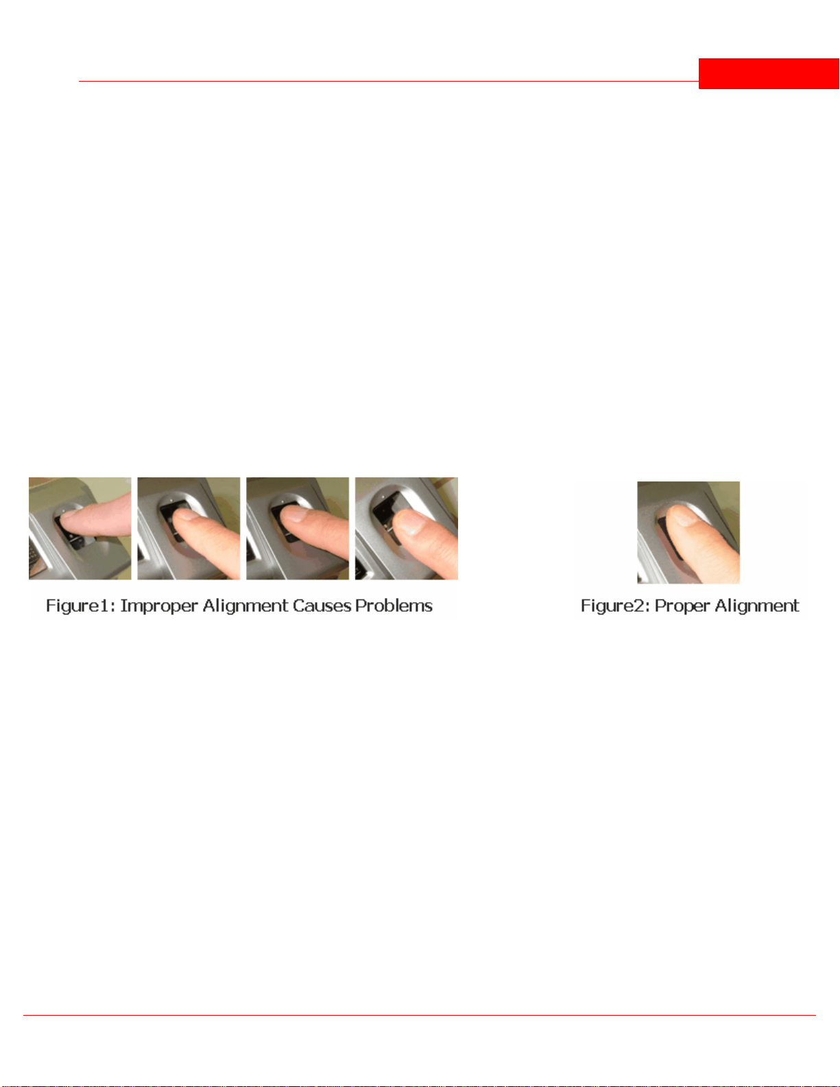
Position of the Finger
In order to capture the most minutiae, maximize the surface area of the fingerprint on the fingerprint input window by
covering the sensor completely. It is okay for the fingertip to extend beyond the length of the sensor to center the
fingerprint. Apply pressure lightly and evenly without moving it during the capturing process. Figure2 shows the
correct positioning of the fingerprint on the input window. Figure1 shows the most common mistakes made during the
initial phase of enrollment.
When the Red light (Fingerprint Scanner) is on, slide the finger across the scanner.
1. Position the finger where the first joint of the finger meets the edge of the sensor.
2. Lower the finger onto the sensor and apply moderate pressure.
3. Keep the finger on the sensor until the Red light (fingerprint scanner) turns off. You may then remove the finger
Getting Good Fingerprint Images
The quality of a fingerprint image is relative to the number of minutiae points captured. If the number and locations
of the minutiae remain consistent whenever an individual's fingerprint image is scanned and captured, the fingerprint
image is successfully matched to the template of the registered finger. Fingerprint images that do not contain
© 2012 IDTi

BSC-101 V.4 Operations Manual5
adequate minutiae data are not acceptable as personal credentials, and are therefore invalid. Figure 3 shows poorquality fingerprints, characterized by smudged, faded, or otherwise distorted areas on the fingerprint. Conditions like
these may be attributable to a number of factors, including excessively dry or wet skin, or scarring.
1. Use index, middle or ring fingers
2. Avoid using thumb and pinky fingers since they are typically awkward to consistently position on the sensor
3. Completely covering the area of the sensor with the fingerprint will provide the best performance
© 2012 IDTi

BSC-101 Operations Manual
Part
III
BSC-101 V.4 Operations Manual7
1
Press F1/P key to enter system mode.
2
Key in administrator ID followed by the #
key
3
Present either finger or card which ever
administrator has been enrolled with. For
now we will use the fingerprint
4
Finger scanning message will appear
5
Now you're into system mode.
Press F1 key to scroll up the main menu
Press F2 key to scroll down the main menu
3 Quick Start
3.1 Pre-Installation Checklist
Make sure all wires are checked.
Check for communication module. There are several types of communications, Ethernet. Make sure you have the
correct communication modules.
Set network address. All devices are defaulted to address 1. If you're connecting 2 or more, change network
address to 2 and up.
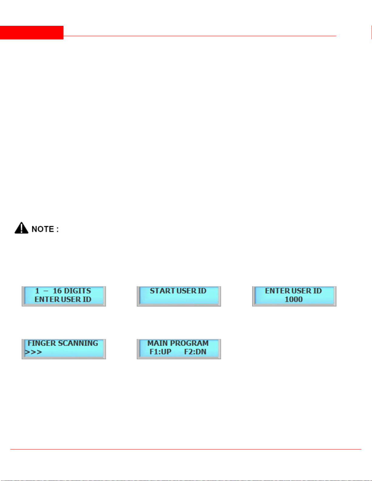
3.2 Entering the System Menu
When the reader is powered on with no fingerprint templates enrolled in the unit, anyone can enter the system menu
by pressing the F1/p key. If you are enrolling the first administrator card via the reader's keypad, you must first
determine the 1~16 digit PIN that the administrator will use. Once this PIN is determined, the administrator must be
present to enroll their card into the reader. Note that this operation is not valid if there are administrator card in the
reader.
Device factory default has no system administrator password. If you've just purchased the unit, you should be able to
get into the system mode by pressing the F1 key.
3.2.1 If Administrator has been enrolled
© 2012 IDTi
Quick Start 8
1
Press F1/P key to enter system mode
2
Now you're into system mode.
Press F1 key to scroll up the main menu
Press F2 key to scroll down the main menu
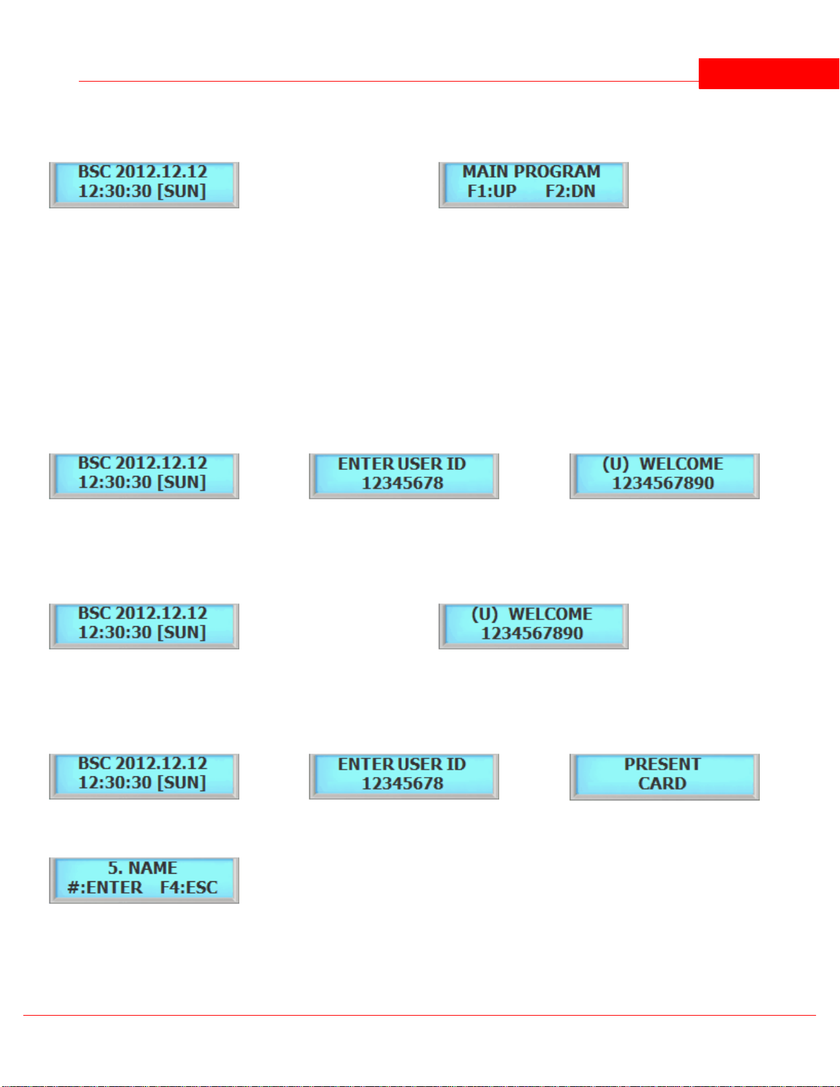
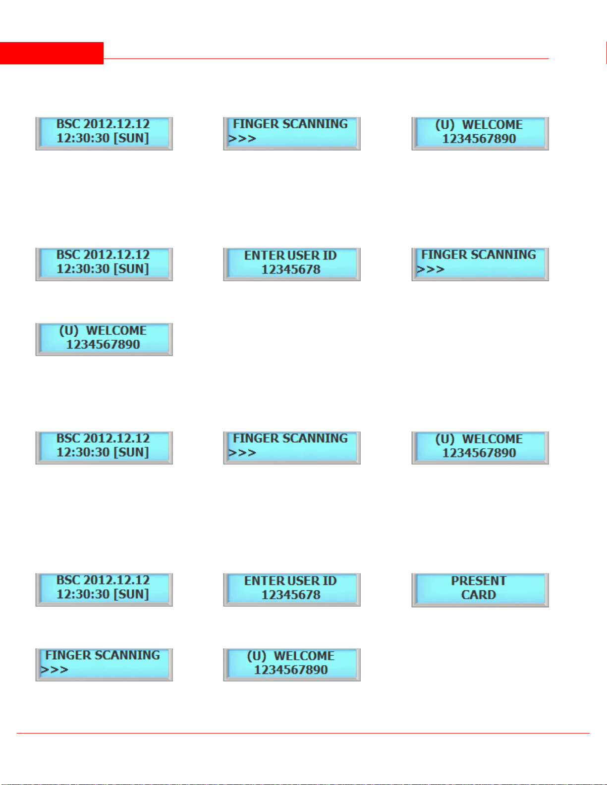
1
From the standby menu, key in user PIN
and press the # key.
2
Enter user PIN and press the # key.
3
Welcome message will appear if the
verification has been successful.
1
From the standby menu, present user card to the reader.
2
Welcome message will appear if the verification has been
successful.
1
From the standby menu, key in user PIN
and press the # key.
2
Key in user PIN followed by the # key
3
Present user Card to the reader.
4
Welcome message will appear if the
verification has been successful.
3.2.2 If no Administrator has been enrolled
3.3 Operating System
To use the system, simply enter enrolled user fingerprint to the scanner. Touch sensor will automatically activate the
fingerprint sensor when user finger is presented to the scanner. Remove the finger when red scanning light turns off.
There are 11 operating modes in the system, depending on which mode is running, operating the system varies.
3.3.1 Operating with User PIN
3.3.2 Operating with User CARD
3.3.3 Operating with User PIN & CARD
© 2012 IDTi
BSC-101 V.4 Operations Manual9
1
From the standby menu, present user
fingerprint to the scanner. If the scanner
doesn't turn on then press the # key to
manually turn scanner on.
2
Enter user fingerprint to the scanner.
3
Welcome message will appear if the
verification has been successful.
1
From the standby menu, key in user PIN
and press the # key.
2
Once the user ID has been entered,
fingerprint scanner will flash red.
3
Enter user fingerprint to the scanner.
4
Welcome message will appear if the
verification has been successful.
1
From the standby menu, present user card
to the reader. Fingerprint scanner will
flash red, once the user card has been
verified.
2
Enter user fingerprint to the scanner.
3
Welcome message will appear if the
verification has been successful.
1
From the standby menu, key in user PIN
and press the # key.
2
Once the user ID has been entered,
fingerprint scanner will flash red.
3
Present user Card to the reader.
4
Present user fingerprint to the scanner.
5
Welcome message will appear if the
verification has been successful.
3.3.4 Operating with User FINGERPRINT
3.3.5 Operating with User PIN & FINGERPRINT
3.3.6 Operating with User CARD & FINGERPRINT
.
3.3.7 Operating with User PIN & CARD & FINGERPRINT
© 2012 IDTi
Quick Start 10
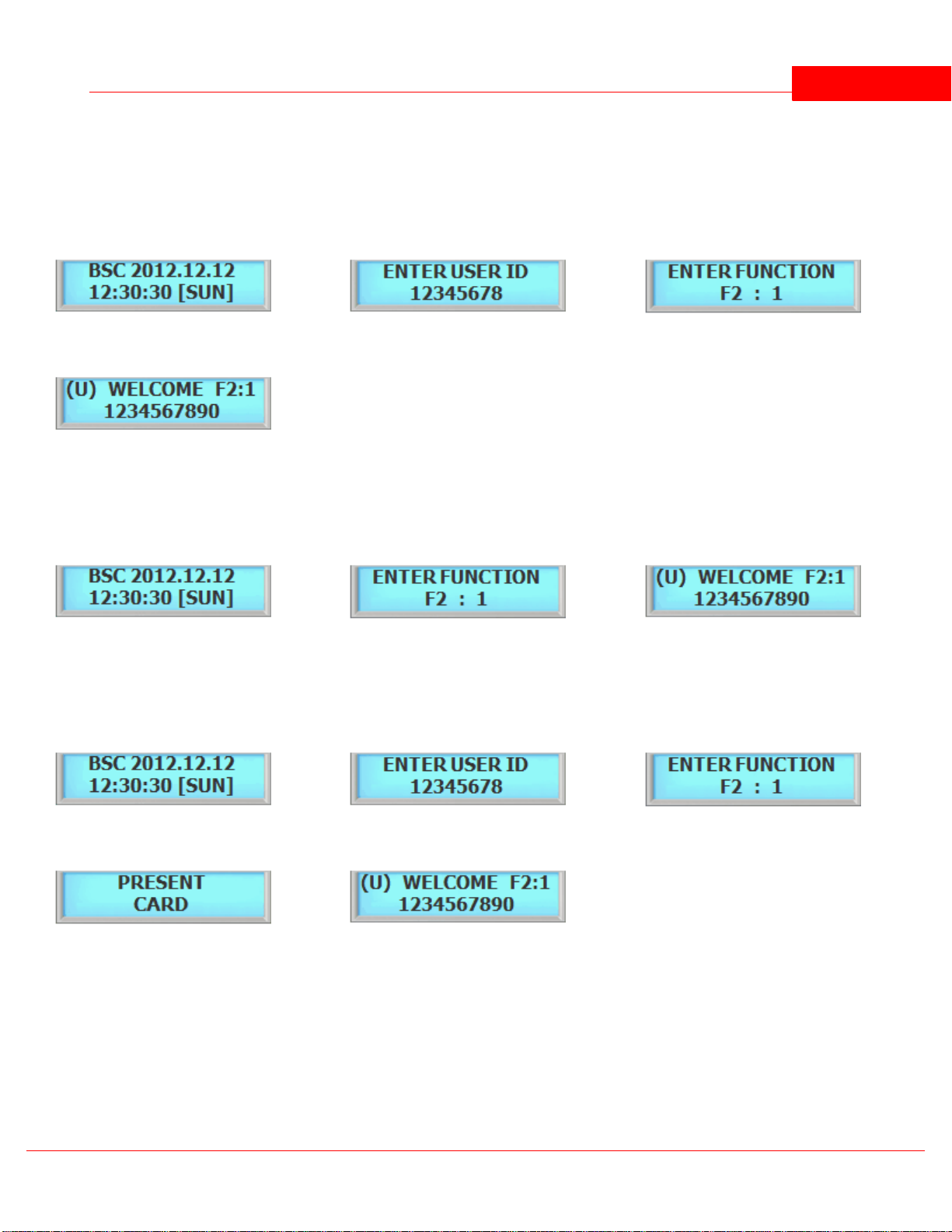
1
From the standby menu, key in user PIN
and press the # key.
2
Once the user ID has been entered press
the function key but DO NOT PRESS # KEY
3
Enter the function key.
4
Welcome message with function key will
appear if the verification has been
successful.
1
From the standby menu, key in user PIN
and press the # key.
2
Enter function key followed by presenting
user card.
3
Welcome message with function key will
appear if the verification has been
successful.
1
From the standby menu, key in user PIN. DO
NOT PRESS THE # KEY.
2
Key in user PIN but do not press the # key.
3
Enter function key followed by presenting
user card.
4
Present user Card to the reader.
5
Welcome message with function key will
appear if the verification has been
successful.
3.4 Operating the System with Funtion Key
There are 5 operating modes in the system, depending on which mode is running, operating the system varies.
3.4.1 Operating Function Key in PIN
3.4.2 Operating Function Key in CARD
3.4.3 Operating Function Key in PIN and CARD
© 2012 IDTi
BSC-101 V.4 Operations Manual11
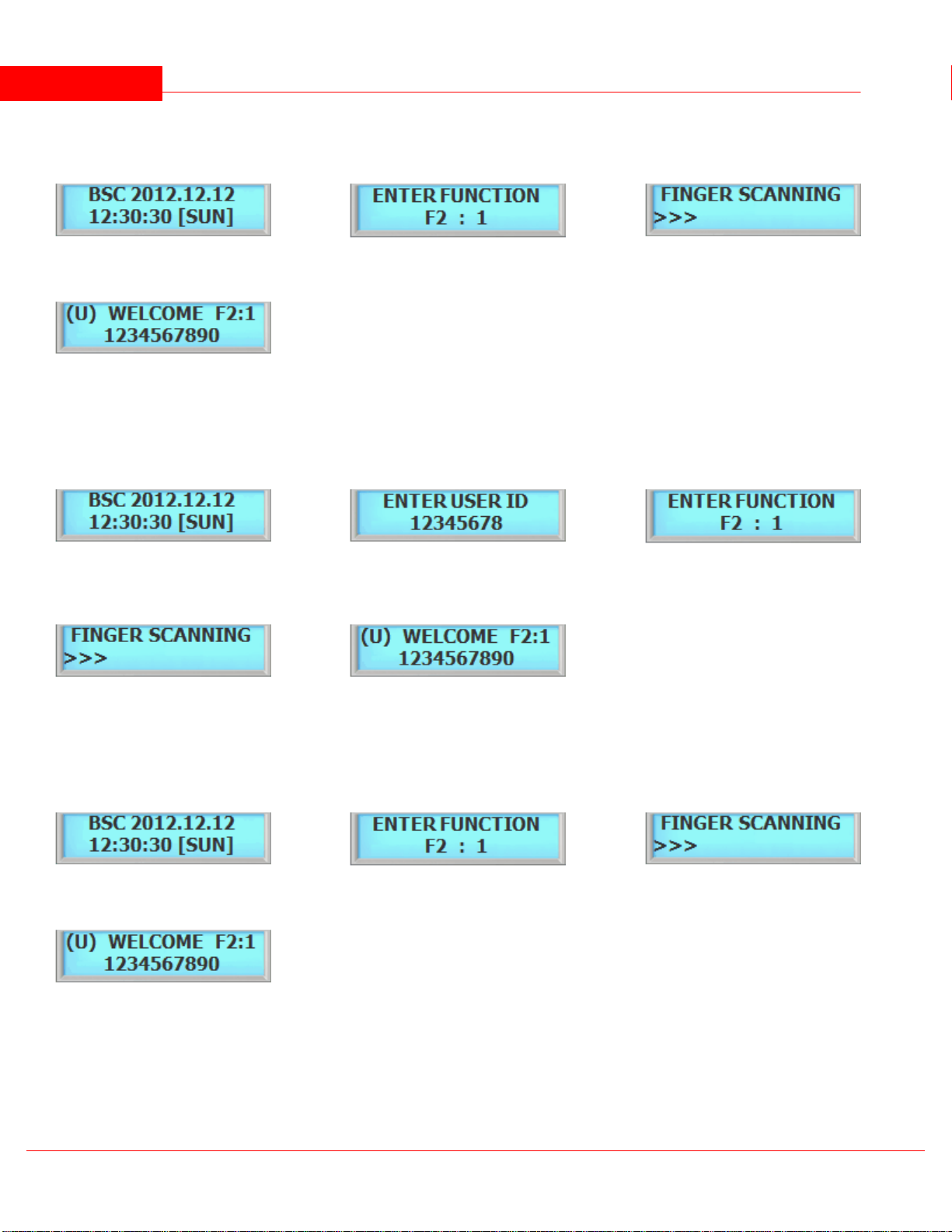
1
From the standby menu, key in user PIN
and press the # key.
2
Press function key followed by presenting
user card.
3
Enter user fingerprint to the scanner.
4
Welcome message with function key will
appear if the verification has been
successful.
1
From the standby menu, key in user PIN
and press the # key.
2
Key in user PIN but do not press the # key.
Once the user PIN is entered, enter the
function key
3
Press function key. Enter user fingerprint.
4
Present user fingerprint to the scanner.
5
Welcome message with function key will
appear if the verification has been
successful.
1
Standby menu....
2
Press function key followed by presenting
user card.
3
Enter user fingerprint to the scanner.
4
Welcome message with function key will
appear if the verification has been
successful.
3.4.4 Operating Function key in FINGERPRINT
3.4.5 Operating Function key in PIN & FINGERPRINT
3.4.6 Operating Function key in CARD & FINGERPRINT
© 2012 IDTi

3.4.7 Operating Function key in PIN & CARD & FINGERPRINT
1
From the standby menu, key in user PIN. DO
NOT PRESS THE # KEY.
2
Key in user PIN but do not press the # key.
3
Press function key then present user Card.
4
Present user Card to the reader. Fingerprint
scanner will flash red
5
Present user fingerprint to the scanner.
6
Welcome message will appear if the
verification has been successful.
Quick Start 12
© 2012 IDTi

BSC-101 Operations Manual
Part
IV

SYSTEM MENU 1 - ENROLL USER 14
1
Press the # key to add users Fingerprint
Template
2
Press 1 for User and press 2 for Admin
3
Key in user ID from 1 to 16 digits as shown
in next figure
4
Key in user ID followed by the # key
5
System has an option to enroll 2 fingerprint
templates and 4 fingerprint templates per
each user. For now we will select number 2
key by enrolling 4 templates
6
Present first finger to the scanner. Remove
the fingerprint when the red light turns off.
You can either enroll same fingerprint or
different fingerprint after the first. Repeat
this process until the last fingerprint
7
Scanning the last fingerprint.....
8
Enroll completed. Press the # key to
continue enrolling another user fingerprint
or press any others to exit off the sub-menu
4 SYSTEM MENU 1 - ENROLL USER
4.1 1. Enroll Fingerprint User
This command is used to add typical fingerprint only users to the reader so that they will be able to gain entry to the
location guarded by the reader. The system has an option to enroll either 2 or 4 templates per user. The following key
sequence performs this action:
When the Red light (Fingerprint Scanner) is on, slide the finger across the scanner.
1. Position the finger where the first joint of the finger meets the edge of the sensor.
2. Lower the finger onto the sensor and apply moderate pressure.
3. Keep the finger on the sensor until the Red light (fingerprint scanner) turns off. You may then remove the
finger.
Use thumb, index, middle or ring fingers.
Avoid using pinky fingers since its typically awkward to consistently position on the sensor.
Completely covering the area of the sensor will provide the best performance.
© 2012 IDTi
BSC-101 V.4 Operations Manual15
There are 2 levels of administration,
1. USER (Level 1) - Corresponds to an ordinary user. They may verify, but are not allowed to access any
administrative functions.
2. ADMIN (Level 4) - This is an system administrator level and has full rights to configure the reader.
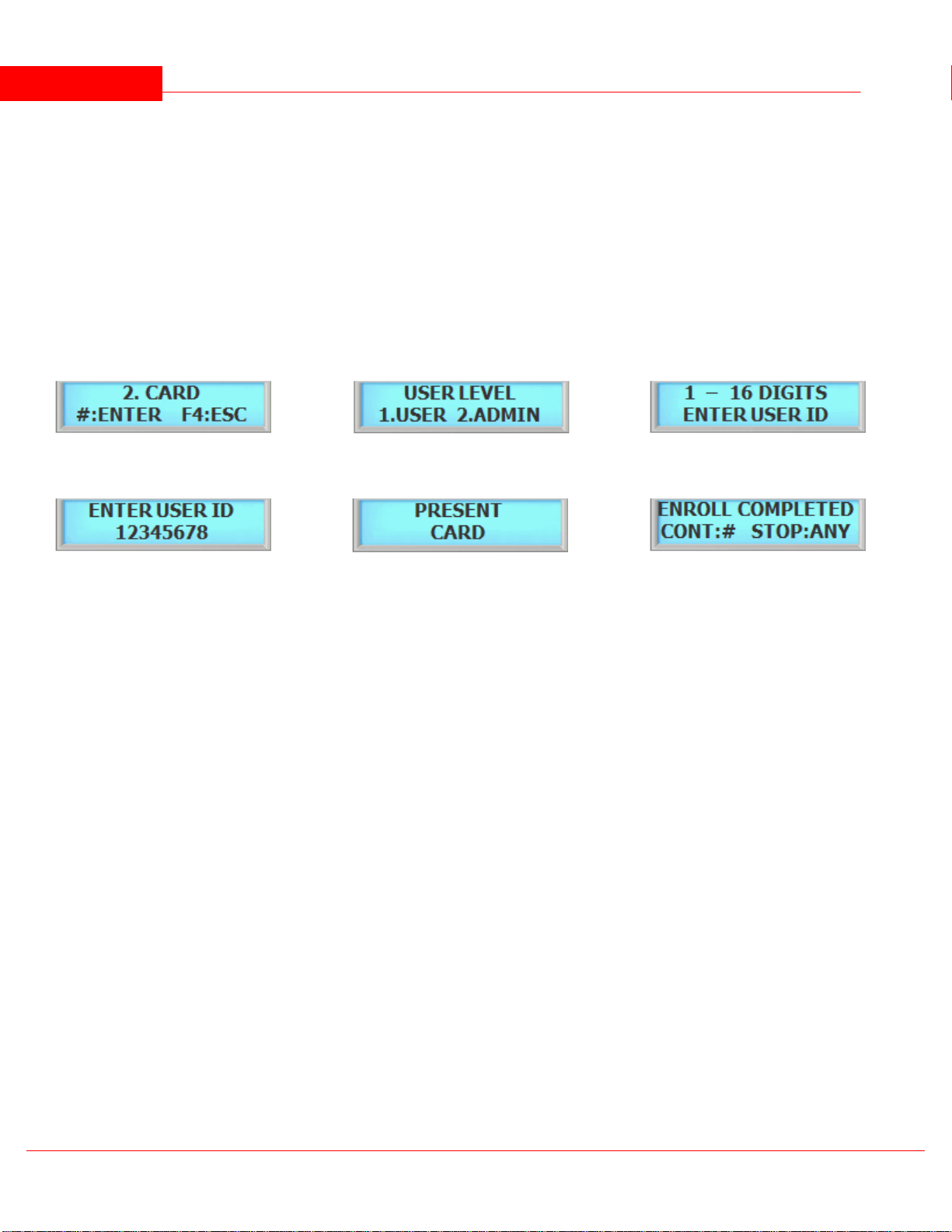
1
Press the # key to add user card
2
Press 1 for User and press 2 for Admin
3
Key in user ID from 1 to 16 digits as shown
in next figure
4
Key in user ID followed by the # key
5
Present user card to the reader or key in
card number manually followed by the #
key
6
Enroll completed. Press # key to continue
adding card or press any other key to exit
off the sub-menu
4.2 2. Enroll Card User
This command is used to add typical card only users to the reader so that they will be able to gain entry to the
location guarded by the reader. The following key sequence performs this action:
4.3 3. Enroll Card and Fingerprint User
This command is used to add typical fingerprint and card users to the reader so that they will be able to gain entry to
the location guarded by the reader. The following key sequence performs this action:
© 2012 IDTi

SYSTEM MENU 1 - ENROLL USER 16
1
Press the # key to add users fingerprint and
card
2
Press 1 for User and press 2 for Admin
3
Key in user ID from 1 to 16 digits as shown
in next figure
4
Key in user ID followed by the # key
5
System has an option to enroll 2 fingerprint
templates and 4 fingerprint templates for a
single user. For now we will select number
2 key by enrolling 4 templates.
6
Enter in first fingerprint. You can either
enroll same fingerprint or different
fingerprint after the first. Repeat this
process.
7
Scanning last finger
8
Present user card to the reader
9
Enroll completed. Press the # key to
continue enrolling another user or press
any others to exit off the sub-menu
4.4 4. Enroll Block of Card User
This command is used to enroll range of cards, block enrollment by card number range is best used when there are
large quantity of sequential ID numbered cards or credentials. Cards or credentials do not have to be on hand when
enrolled through the block enrollment by card number range process, but you must have the facility code. Below is an
example to enroll 100 Users with card number starting with 1000. User ID 1000 will be addressed to card number
1000, User ID 1001 will be addressed to card number 1001 and so on. Card must be in sequential order to use the
Card Block. Please check with your card provider for more information.
© 2012 IDTi

BSC-101 V.4 Operations Manual17
1
Press the # key to add block of card user.
2
Enter in first number of the block ID. This
will be the first ID number of the card as
shown in the next figure
3
1000 would be the first number of user ID
4
Following message will appear. Enter in the
first card number as shown below
5
1000 would be the first number the card
6
Following message will appear. Enter in
the total number of cards to be enrolled as
shown below
7
100 would be the total number of cards to
be enrolled
8
Enrolling user card block. Please wait unit
the process finishes. This might take up to 5
minutes depending on the total number of
card block size.
9
Enroll completed. Press the # key to
continue adding another or press any
others to exit off the sub-menu
Start
End
User ID
User ID 1
User ID 2
User ID 3
User ID 4
User ID5
User ID 6
Card #
Card # 10
Card # 11
Card # 12
Card # 13
Card # 14
Card # 15
System
Memory
Not Used
In Use
Not Used
In Use
Not Used
Not Used
Result
YesNoYesNoYes
Yes
This option will write block of cards in empty slots of the memory and will not delete enrolled users. Using Card Block
1 requires more time than card block2 since it will search for empty slots in memory to enroll. Consider using card
block2 if the memory is empty or stored memory is no longer needed.
In this case only 4 user ID and cards will be recorded in to system and even though 6 user and 6 cards are being
enrolled using Card Block. When using card block, system will group user id and card numbers together. So if User ID
is already in use in system, then card corresponding to the user id will not be recorded and left out.
4.5 5. Enroll Block of Card User 2
This command is used to enroll range of cards, block enrollment by card number range is best used when there are
large quantity of sequential ID numbered cards or credentials. Cards or credentials do not have to be on hand when
enrolled through the block enrollment by card number range process, but you must have the facility code. Below is an
example to enroll 100 Users with card number starting with 1000. User ID 1000 will be addressed to card number
1000, User ID 1001 will be addressed to card number 1001 and so on.
© 2012 IDTi

SYSTEM MENU 1 - ENROLL USER 18
1
Press the # key to add block of card user.
2
Enter in first number of the block ID. This
will be the first ID number of the card as
shown in the next figure
3
1000 would be the first number of user ID
4
Following message will appear. Enter in the
first card number as shown below
5
1000 would be the first number the card
6
Following message will appear. Enter in
the total number of cards to be enrolled as
shown below
7
100 would be the total number of cards to
be enrolled
8
Enrolling user card block. Please wait unit
the process finishes. This might take up to 5
minutes depending on the total number of
card block size.
9
Enroll completed. Press the # key to
continue adding another or press any
others to exit off the sub-menu
This option will write block of cards without checking memory slots and will delete currently enrolled user. All
existing User ID along with card numbers will be replaced.
© 2012 IDTi

BSC-101 Operations Manual
Part
V

SYSTEM MENU 2 - EDIT USER 20
1
Press the # key to enter edit User ID
2
Key in user ID to be edited followed by the #
key
3
Key in new user ID followed by the # key
4
Edit completed. Press the # key to continue
editing another or press any others to exit
off the sub-menu
1
Press the # key enter user FINGER
2
Key in user ID to be edited followed by the # key
3
Press 1 to add 2 templates
Press 2 to add 4 templates
4
Enter in the first fingerprint. You can either add
same fingerprint or different fingerprint after the
first. Repeat this process until the fourth
fingerprint.
5
Scanning the last finger....
6
Edit completed. Press the # key to continue
editing another or press any others to exit off the
sub-menu
5 SYSTEM MENU 2 - EDIT USER
5.1 1. Edit User ID
This command is used to edit existing users ID by accessing the user ID. When editing, Administrators have the
ability to make changes to user ID only in this menu.
5.2 2. Edit User Fingerprint
This command is used to edit existing users Fingerprint by accessing the user ID. When editing, Administrators have
the ability to make changes to user Fingerprint only in this menu.
5.3 3. Edit User Card
This command is used to edit existing users Card by accessing the user ID. When editing, Administrators have the
ability to make changes to user Card only in this menu.
© 2012 IDTi

BSC-101 V.4 Operations Manual21
1
Press the # key to enter edit user CARD
2
Key in user ID to be edited followed by the # key
3
Present new card to be enrolled or enter in the
card number manually followed by the # key.
Make sure the card has not been already enrolled
in the system
4
Edit completed. Press the # key to continue editing
another or press any others to exit off the submenu
1
Press the # key to enter edit user LEVEL
2
Key in user ID to be edited followed by the # key
3
Press 1 for User and pres 2 for admin
4
Edit completed. Press the # key to continue editing
another or press any others to exit off the submenu
There are 2 levels of administration:
1. USER (Level 1) - Corresponds to an ordinary user. They may verify, but are not allowed to access any
administrative functions.
2. ADMIN (Level 4) - This is an system administrator level and has full rights to configure the reader.
5.4 4. Edit User Level
This command is used to edit existing users level by accessing the user ID. User levels determine where a user will
be valid. To edit an existing user edit user level, follow the steps below.
5.5 5. Edit User Name
The device is able to display custom user name instead of user ID when accessed. When the system is expecting a
name then the number keys on the keypad become letter keys: the letters below the keys apply. Press once to show
the first uppercase letter above the key; press four times to show the lowercase letter. When the desired letter
appears on the display, press the up-arrow(F1) to move on to the next letter in the name.
© 2012 IDTi

SYSTEM MENU 2 - EDIT USER 22
1
Press the # key to enter NAME
2
Key in user ID to be edited followed by the # key
3
Press 1 key to enter user name
4
Key in text as shown in next figure. Continue on
pressing the key to rotate from uppercase letters
to lowercase letters. i.e. to display lowercase "c"
press the number 2 key 6 times. Use the F1 key as
space
5
Key in appropriate display name and then press
the # key
6
Press the # key to continue editing the display
option. Display option must be configured in
order for it will work properly
7
Once again, enter in same ID you have just edited
previously
8
This time select #2 to enter display option
9
Select #2 to display ID by name. This will allow the
system to display custom ID name instead of user
ID
10
Edit completed. Press the # key to continue editing
another or press any others to exit off the submenu
NUMBER OF TIMES KEY IS PRESSED
KEYS12345678
12ABCabc3DEFdef4GHIghi5JKLjkl6MNOmn
o
7PQRSpqrs
8TUVtuv
9WXYZwxyz0*
Clear
#
Enter
F1
Space
F2
F3
Back Space
F4
Escape
© 2012 IDTi

BSC-101 V.4 Operations Manual23
1
Press the # key to enter USER ANTIPASS
2
Enter user ID to apply anti-pass followed by the #
key
3
Press 1 key to enable anti-pass
Press 2 key to disable anti-pass
Press 3 key to forgiveness
Refer to NOTE for clearing the anti-pass
4
Edit completed. Press the # key to continue adding
another user fingerprint or press any others to exit
off the sub-menu
Anti-pass must be enabled in system setting. Before enabling the anti-pass in user setting, go to main menu
5.SYSTEM SETTING/submenu 12.ANTI PASS and enable the anti-pass for system
When the system has detected an anti-pass user, that user will be denied the access to that location. Administrator
must clear that person of anti-pass by going into edit option and reset the anti-pass by selecting 3(CLR) forgiveness
5.6 6. User Antipass
Anti pass-back is used to stop two people from using one card to gain access. This feature is designed to protect
against tailgating. Once an access is granted to an IN reader, it must be presented to an OUT reader before another
IN reader access is granted. In the event that the user did not read in at the IN reader, and tried to read out of an
area, an anti-passback violation would occur. The violation may just log the event as an alarm condition, or may not
allow the door to be released. Since users who fail to read IN and walk in with other employees may get stranded or
locked in. System Anti-Passback must be enable in order for User Anti-passback to work properly.
5.7 7. Option (ID)
ID Option is a special mode where user can access the unit with ID only. When applied, user can override the current
operating mode and access unit it with just an ID (PIN). This option can be applied to those users who does not have
card. To apply this mode to user, follow the steps bellow.
© 2012 IDTi

SYSTEM MENU 2 - EDIT USER 24
1
Press the # key to enter OPTION (ID)
2
Enter user ID to apply ID option followed by the #
key
3
Press 1 key to enable ID option to this user
Press 2 key to disable ID option to this user
4
Edit completed. Press the # key to continue editing
another or press any others to exit off the submenu
1
Press the # key enter USER TWO MAN
2
Enter user ID to apply two man function followed by
the key.
3
Press 1 to enable two man for this user
Press 2 to disable two man for this user
4
Edit completed. Press the # key to continue editing
another or press any others to exit off the submenu
5.8 8. User Two Man
This commend prevents an individual user from entering a selected empty security area unless at least one other
enrolled user is present. Once two enrolled users are logged into the area, other user can come and go individually,
as long as at least two people are in the area. Conversely, when exiting, the last two occupants of the security area
must exit out together. At no time will the system allow less than two users to be in the area.
Two Man must be enabled in system setting. After enabling User Two Man option, go to main menu 5.SYSTEM
SETTING/submenu 13.TWO MAN and enable the TWO MAN for system.
5.9 9. Restriction TIme
Restriction Time limits how many times a user can be allowed to access depending on value assigned to a user.
There are 4 values that can be given to a user. (Ex. if a value of 1-H is given to a user. This user will only be allowed
to access once every hour. User must wait another 1 hour to regain its access.)
© 2012 IDTi

BSC-101 V.4 Operations Manual25
1
Press the # key enter Restriction Time.
2
Enter user ID and press the # key
3
Select from 1 to 4. Below explains the detail
3
Edit completed.
30-M: Once every 30 minutes.
1-H: Once every hour.
1-D: Once every day.
FULL: No limit.
1
Press the # key enter Canteen Count
2
Enter User ID and press the # key
3
Press 1 to turn on Restriction Count
Press 2 to turn off Restriction Count
4
Enter from 1 to 99 and press # key
4
Edit completed.
5.10 10. Restriction Count
Restriction Count limits how many times a user can be allowed to access depending on value assigned to a user.
There are total of 99 values that can be given to a user. (Ex. if a value of 10 is given to a user. This user will be
allowed to access 10 times and it will expire. User must wait a day to regain its access or clear access permission
from the administrator.)
5.11 11. Restriction Type
This option allows the device to automatically reset canteen time. All user will be able to access the next following
day even if the the user has been limited access to Restriction count.
© 2012 IDTi
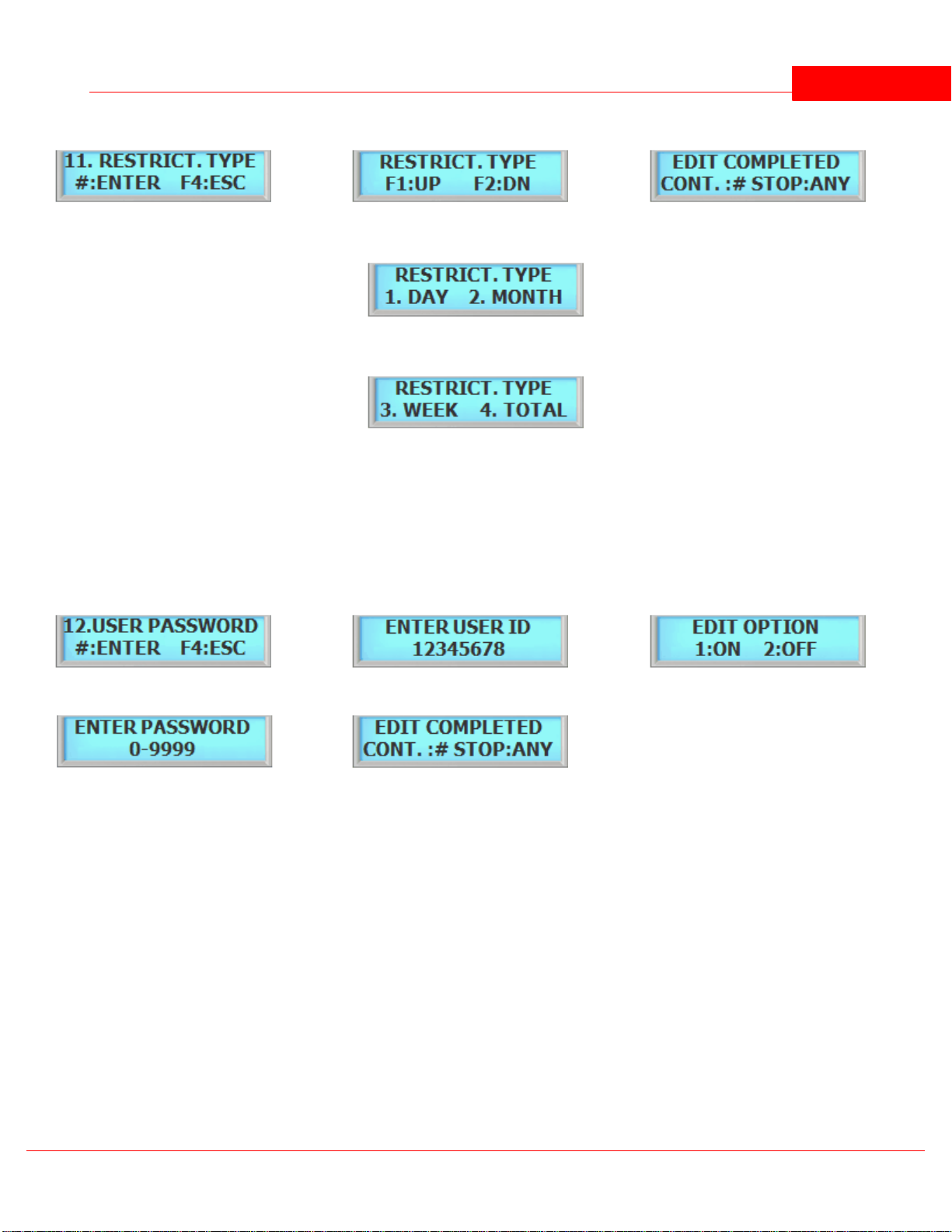
1
Press the # key enter Canteen Count 1 day reset
2
Press F1 to scroll up
Press F2 to scroll down
3
Edit completed.
2-1
1. DAY: Reset every day midnight.
2. MONTH: Reset every 1st day of month
.
2-2
3. WEEK: Reset every Monday
4. TOTAL: Reset when total count is used
5.12 12. User Password
1
Press the # key to enter Firmware Update.
2
Enter User ID and press the # key.
3
Press 1 to enable password.
4
Enter password from 0 to 9999 and press
the # key.
5
Setup has completed
SYSTEM MENU 2 - EDIT USER 26
User Password enables the device to be use a password instead of User ID (PIN). Once enabled, user must enter a
User ID (PIN) number and the password to access. Password only works in ID or Card or FP mode (All Mode).
© 2012 IDTi

BSC-101 Operations Manual
Part
VI
SYSTEM MENU 3 - VIEW USER 28
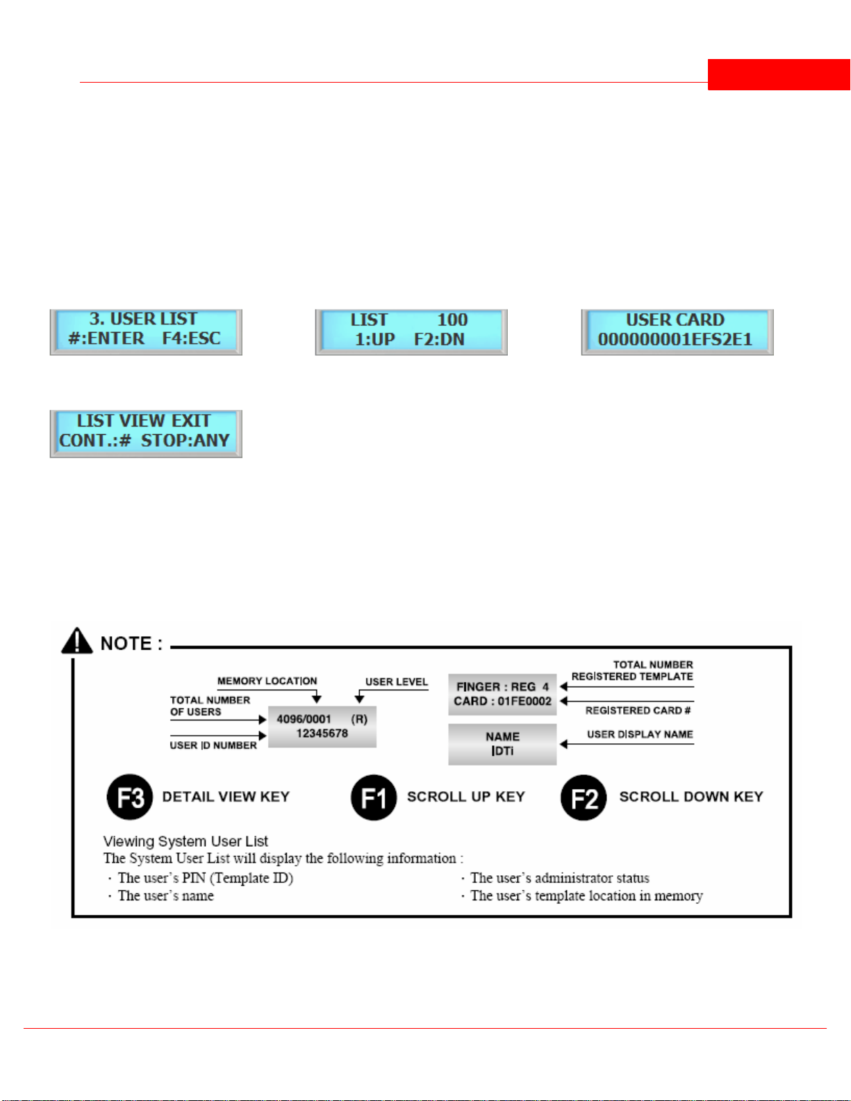
1
Press the # key to enter to view USER LIST
2
Press F1/P key to scroll up the user list
Press F2 key to scroll down the user list
3
Press F3 key to view detail view of user
4
Press the F4 key to exit view.
Viewing System User List
The System User List will display the following information:
. The user's PIN (Template ID)
. The user's name
. The user's administrator status
. The user's template location in memory
6 SYSTEM MENU 3 - VIEW USER
6.1 1. User List
At any time, you can view a list of all users of the system. The list can be an overall enrollment list of all users in the
system, or it can be a list of the individual users that are physically enrolled on any individual fingerprint reader.
© 2012 IDTi

BSC-101 V.4 Operations Manual29
1
Press the # key to enter view EVENT
2
Press F1 to scroll up the event log
Press F2 key to scroll down the event log
3
Following event log will appear. Press F3 key to
view event data
4
Press the F4 key to exit event view.
Viewing System Event Log
The System Event Log List will display the following information:
. The date of event occurrence
. The time of event occurrence
. The total number of event log
6.2 2. Events
At any time, you can view all transaction of event logs of the system. A record created that contains pertinent
information about an occurrence in the access control and monitoring system.
6.3 3. Firmware
This is to view the current firmware version installed in the system. Other ways to verify the firmware is to resetting
the device. When first booting up, firmware version will display.
© 2012 IDTi

SYSTEM MENU 3 - VIEW USER 30
1
Press the # key to enter FIRMWARE VERSION
Current firmware version number will display.
Press the any key to view board version.
3
Press any key to exit.
1
Press F4 key to exit.
© 2012 IDTi

BSC-101 Operations Manual
Part
VII

SYSTEM MENU 4 - DELETE USER 32
1
Press the # key to enter delete Single User
2
Enter in user ID to be deleted as shown below
3
Enter in user ID from 1 to 16 digits
4
Delete completed.
1
Press the # key to enter delete All User
2
Press the # key to confirm delete all
Press any other key to cancel
33
Deleting. Please wait....
4
Delete completed.
7 SYSTEM MENU 4 - DELETE USER
7.1 1. Delete Single User
Deleting a fingerprint template from a reader will prevent that template from being granted access to the location via
the reader. Any fingerprint template can be removed from a fingerprint reader, including administrative and the last
remaining fingerprint template on the reader. Templates can be deleted by a single user or all users including
administrative templates.
7.2 2. Delete All User
Deleting a all user will erase all template from a reader, including administrative and the last remaining fingerprint
template on the reader.
© 2012 IDTi

BSC-101 Operations Manual
Part
VIII

SYSTEM MENU 5 - SYSTEM SETUP 34
1
Press the # key to enter system Time
2
Enter current date
3
Enter current time in military time format. i.e.
20:20:20
4
Select day of the week. Press 1 through 7 to enter
day of the week. Refer to NOTE
5
Press the # key to confirm
6
Set up has completed
1
[ID / CD] - PIN or CARD
User can access the device by either PIN or
2
[CD] - CARD
In this mode, user can access the device by
3
[ID&CD] - PIN & CARD
User must use both tokens to gain access.
8 SYSTEM MENU 5 - SYSTEM SETUP
8.1 1.Time
Device features an internal clock that provides the date and time for all logged events. This section discusses how to
set the date and time that device uses for event logging. To set the current time, access the menu system and follow
these steps:
8.2 2. Operating Mode
System has 5 total operating mode. List is the detail view of the operating modes available in the system.
© 2012 IDTi

BSC-101 V.4 Operations Manual35
CARD. When operating in this mode, simply
enter user ID or CARD to the device.
just a card. To operate in this mode, user
present the card to the reader.
This is the highest security mode available
in ISC. To operate in this mode, first enter
user PIN and present user card to the
reader.
4
[OPEN] - ALWAYS OPEN
Access point will stay open for an
emergency such as fire.
5
[CLOSE] - ALWAYS CLOSE
Access point will stay locked for an
emergency such as intrusion.
6
[TESTING MODE] - TESTING MODE
It will be a good idea to test the unit in this
mode when first installed.
&: means "AND"
/: means "OR"
( ): means "OR"
1
Press the # key to enter Operating Mode.
2
Press F1 key to scroll up the mode menu
Press F2 key to scroll down the mode menu
Press the # key to select operating mode
3
Select 1 to enable Operating mode for external
reader
Select 2 to disable Operating mode for external
reader
NOTE: External reader must be connected to
READER 2. Once enabled, the connected reader 2
will operate in ID & CARD mode.
4
Setup completed
1
Press the # key to enter Re-Lock Time
2
Key in Re-Lock Time from 1 to 99 second followed
by the # key. C stands for current set time, sample
show 4 second.
3
Setup has completed
8.2.1 Setting Operating Mode
This section provides information about how to choose the operation mode. ID/CD (ALL) is the default operating
mode.
8.3 3. Re-Lock Time
This is the maximum duration that the lock release relay will be energized. The relay is de-energized if the door opens
before this time has expired. The lock time can be set in the range 01~99 seconds. You cannot set a lock time of 0
seconds. Default is 4 seconds.
© 2012 IDTi

SYSTEM MENU 5 - SYSTEM SETUP 36
1
Press the # key to enter Address
2
Press 1 to setup System Address.
NOTE: SYSTEM ADDRESS is used in Online
Verification and GSM Mode.
3
Enter from 1 to 65,534 and press the # key.
NOTE: there can be up to 65,534 system
addresses.
3
Setup completed.
1
Press the # key to enter Communication Password
2
Press 1 to enable communication password
3
Current password is displayed. Enter new
password as show in next figure
4
Key in the 8 digit password and press the # key to
confirm new password
4
Setup has completed
8.4 4. Address
Address options allows system to have a unique identification code used in Online Verification or GSM Network. To
assign a Network ID, follow the steps listed below: Repeat this procedure for each networked unit, assigning a unique
identification code to each unit. Default address is set to 1.
8.5 5. Communication Password
Communication password is used during network communication. This safeguards the information sent during
transmission and also from hacking the system.
8.6 6. Site Code
A site code, which is sometimes called a facility code, differentiates one users card group from another. A facility
code is an integral code that is programmed into the card at the time of manufacture. The additional code ensures
that even if card numbers are duplicated by the manufacturer, that the cards will not operate on someone else's
building who has a different facility code. Limitations inherent in the card manufacturing process result in the ability
to produce a finite card population, after which codes are duplicated. Facility codes overcome this limitation adding a
second code which is checked at the reader. If the facility code does not match the programmed code, entry is
denied.
© 2012 IDTi

BSC-101 V.4 Operations Manual37
1
Press the # key to enter Site Code
2
Press F1 to scroll up the menu
Press 2 to scroll down the menu
Select the card type and press the # key
3
Se"C" stands for current site code which is 255.
Enter from 0 to 255 and press the # key. Default
setting is 255
Setup completed.
NOTE:
There are 10 card types in ISC-101
1. EM. S. 26 Bit
2. 125K S. 26 Bit
3. 125K F. 26 Bit
4. 125K I. 34 Bit
5. MIFARE 32 Bit
6. MIFARE 34 Bit
7. MIFARE2 34 Bit
8. MIFARE2 32 Bit
9. MIFARE 64 Bit
10. MIFARE IDTi64
1
Press the # key to enter System Reset
2
Press 1 to reset system
Press any other key to cancel
3
System resetting message. This may take few
seconds to a minute depending on the size of the
database
4
Setup has completed
8.7 7. System Reset
The system reset will delete all exiting database including the events and resets all system configuration to factory
default.
8.8 8. Event Reset
The Event Database only stores the access records. It does not contain any system information. When executed,
event reset will erase all event logs that are stored in the memory. Run Index Reset to receive events again from the
system stored memory.
EVENT RESET: Resets all events stored by the system.
© 2012 IDTi

SYSTEM MENU 5 - SYSTEM SETUP 38
1
Press the # key to enter Event Reset
2
Press 1 key to reset event
3
Press 1 key to reset event
Press any other keys to cancel
4
Event resetting message. This may take few
seconds to a minute depending on the size of the
event database
5
Event Reset has finished
1
Press the # key to enter Event Reset
2
Press 2 key to reset index
3
Press 1 key to reset index
Press any other keys to cancel
4
Enter Index point from 0 to 614,399. 0 is the start of
the index and 614,399 is the last of the index point
5
Index Reset has finished
1
Press the # key to enter Communication Speed
2
Press F1 key to scroll up the list
Press the F2 key to scroll down the list
There are 7 different communication speed. Select the best setting for your
network.
Default is set to 19,200 baud rate.
Go to Control Panel and make sure the PC baud rate is in sync with the
system.
3
Press F1 key to scroll up the list
Press the F2 key to scroll down the list
INDEX RESET: Resets history index of the event but does not delete stored event information. Index reset
allows the event to be resent to the software from the point where the index point is reset.
8.9 9. Com. Speed
This command sets the baud rate that the system will communicate with the device connected to its serial port. The
baud rate change will become effective immediately upon completion of the command. Default baud rate is 19,200.
© 2012 IDTi

BSC-101 V.4 Operations Manual39
1
Press the # key to enter Door (Relay)
2
There are 2 relays in the system. Select 1 to setup
relay 1 and press 2 to select relay 2
3
Press 1 to set relay as door or press 2 to set relay
as alarm
4
Setup has completed
Relay 1 factory default is Door (lock)
Relay 2 factory default is Alarm
1
Press the # key to enter Two Man
2
Press 1 key to enable two man
Press 2 key to disable two man
3
This is the time limit for the user to make second
verification to the reader after first user has been
verified. "C" Stands for current setting. Key in from
1 to 99 seconds and press the # key
4
Setup has completed
8.10 10. Door Relay
The relay output is Normally Open (N.O.), and toggles shorted when triggered by an event, such as an authentication
or ID failure. The relay can be used to send power to switched items like electric door strikes, door handles, magnetic
hold locks. The alarm can be used to send signals to a alarm panel, controllers or indicators.
8.11 11. Two Man
This commend prevents an individual user from entering a selected empty security area unless at least one other
enrolled user is present. Once two enrolled users are logged into the area, other user can come and go individually,
as long as at least two people are in the area. Conversely, when exiting, the last two occupants of the security area
must exit out together. At no time will the system allow less than two users to be in the area.
8.12 12. Anti Pass Back
Anti pass-back is used to stop two people from using one card to gain access. If access is denied because of this, this
will result in an alarm message to the printer. It may also result in a relay being energized if you have programmed
one to do so. This is a system anti-pass setting and user anti-pass setting also must be enabled in order for it to work
properly.
© 2012 IDTi

SYSTEM MENU 5 - SYSTEM SETUP 40
1
Press the # key to enter Antipass
2
Press 1 key to enable anti pass
Press 2 key to disable anti pass
3
Setup has completed
4
Setup has completed
1
Press the # key to enter Duress
2
Press 1 key to enable duress
Press 2 key to disable duress
3
Key in F2 or F4 to assign duress key. For now we
will key in F2 key
4
Key in from 0 to 9 followed by # key.
5
Setup completed
1
Press the # key to enter Date Format
2
Press F1 key to scroll up the list
Press F2 key to scroll down the list
8.13 13. Duress
Duress is a condition whereby a user may be confronted by an intruder in an effort to gain access to a secure area.
The user can "secretly" signal security that he is entering the secure area under "duress" through the implementation
of a duress feature. This function must be used with a function key in order to work.
To use duress, press F2 - 2 then enter either Card / PIN depending on the current operating mode.
8.14 14. Date Format
System features option to choose time format which are available in Asia time, USA time, and Europe time. This is
where user can customize time format. This section discusses how to choose time format.
© 2012 IDTi

BSC-101 V.4 Operations Manual41
3
Select the right time format for your region. To use custom message, go to Custom Display on next page.
4
Time format has been set
ASIA Time display format
USA Time display format
EUROPE Time display format
CUSTOM 1 Custom message will display with time
display format with European date format. Date is
displayed before the month
CUSTOM 2 Custom message will with time display
format with American date format. Month is
displayed before the date
8.15 15. Custom Display
System features option to customize the display. System Allows up to 32 characters to be displayed. This is where
user can customize main display window. This section discusses how to edit custom display.
© 2012 IDTi

SYSTEM MENU 5 - SYSTEM SETUP 42
1
Press the # key to enter Custom Display
2
Key in alphabet and press the F1 key to move on to
the next letter. To get an lowercase, continue
pressing the key until the lowercase letter
appears. If the name is longer than 16, press the #
key after entering the last last (16th) letter. This
will be continued in next step
3
If the message is longer than 16 digits, press 1 key
to continue on writing the message. Otherwise
press 2 to end writing custom message
4
Continue on writing the message where you've left
off in figure 2
5
Finished editing the custom message
You can enter up to 32 digits. The LCD will scroll the
message if it's longer than 16 digits. To view the
custom display, go to Date Format and set display
option to either Custom 1 or Custom 2 depending on the
date format.
NUMBER OF TIMES KEY IS PRESSED
KEYS12345678
12ABCabc3DEFdef4GHIghi5JKLjkl6MNOmn
o
7PQRSpqrs
8TUVtuv
9WXYZwxyz0*
Clear
#
Enter
F1
Space
F2
F3
Back Space
F4
Escape
8.16 16. LCD Light
System allows you to choose whether the display will be illuminated or unlit. By default, the display is lit for 5
seconds when used. Illuminating the display allows for easier viewing in darker areas while leaving the display unlit
conserves power. This section provides information about how to set illumination options for the system's display
© 2012 IDTi
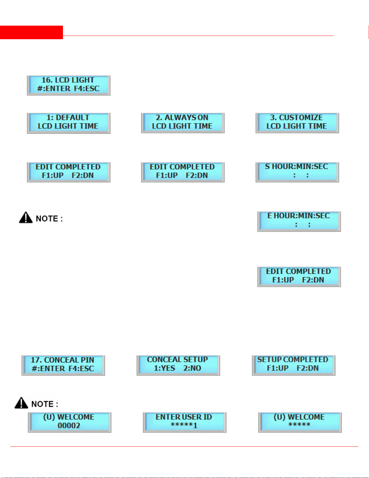
unit.
1
Press the # key to enter LCD Light option
2.1
Press the # key to set it as default time
Press F1 to scroll up the menu
Press F2 to scroll down the menu
2.2
Press the # key to set it as always on
Press F1 to scroll up the menu
Press F2 to scroll down the menu
2.3
Press the # key to set it as customize
Press F1 to scroll up the menu
Press F2 to scroll down the menu
3
Finished editing LCD back light time
3
Finished editing LCD back light time
2.4
Define the start time of LCD. LCD will turn on
according to this time setting. Key in military time
format. For example, 15:15:15 (3:15:15 PM)
There are 3 LCD options:
1. Default: LCD will stay lit for 5 seconds.
2. Always on: LCD will illuminated all times. This will lessen the life of LCD screen.
3. Customize: You can set schedule time for LCD to turn on and turn off.
2.5
Define the end time of LCD. LCD will turn off
according to this time setting. Key in military time
format. For example, 15:15:15 (3:15:15 PM). Press
the # key when finished
3
Finished editing LCD back light time
1
Press the # key to enter Conceal PIN
2
Press 1 key to enable conceal PIN
Press 2 key to cancel the conceal PIN
3
Setup has completed
BSC-101 V.4 Operations Manual43
8.17 17. Conceal PIN
Device allows you to conceal user PIN when entering the device. To hide user PIN when entering the device, follow
the instructions below.
© 2012 IDTi
SYSTEM MENU 5 - SYSTEM SETUP 44
Normal View
Actual view during entrance
Concealed User PIN View
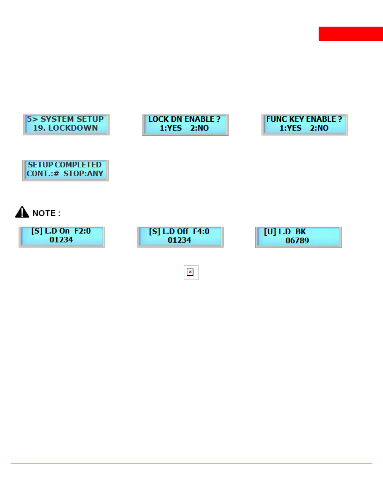
1
Press the # key to enter Lockdown
2
Press 1 key to enable lockdown
Press 2 key to cancel lockdown
3
Press 1 key to enable function key
Press 2 key to disable function key
4
Setup has completed
8.18 18. Lockdown
Device features option to use a auxiliary relay to arm/disarm an external alarm system called the lockdown. This
section discusses how to enable lockdown device.
8.19 19. Attendance
Device features option to display IN or OUT when function keys are used. User must be aware of the current
attendance mode that is displayed in the standby display. Last used attendance mode will be the default mode until
the next mode is used. If F2-0 is used the last time, then unless second user uses a different function key, it will show
as F2-0 even if second user does not press any function key. This section show how to customize the function key
display.
© 2012 IDTi

BSC-101 V.4 Operations Manual45
1
Press the # key to enter Attendance
2
Press 1 to enable attendance mode
3
Select attendance type.
1. 4F-ATT:
2: A-ATT:
3: A-EAT:
7: 2F-ATT:
5
Setup has completed
8.20 20. Network Setup
8.20.1 Device IP Address Setup
System can operate either as Server or Client. If set as Server then the software must be set as Client and if set as
Client then the software must be set as Server.
8.20.1.1Manual Server Mode
In Server Mode, software connects to the device. This would be a ideal network setting since software will
automatically re-connect if the connection is lost.
© 2012 IDTi

SYSTEM MENU 5 - SYSTEM SETUP 46
1
Select network setup from system menu 5.
2
Press 2 key to setup network.
3
Press 2 to enter Device IP address.
4
Press 1 to select Server Mode
4
Manually select communication speed. Default is
set to Auto Negotiation.
Press F1 to scroll up the menu
Press F2 to scroll down the menu
5
Press 1 to disable DHCP mode
6
Enter IP address and press the # key.
(Ex. 192.168.0.10) Enter key192168000010#
7
Enter gateway IP address and press the # key. (Ex.
192.168.0.1) Enter key 192168000001#
8
Enter submask IP address and press the # key. (Ex.
255.255.255.0) Enter key 255255255000#
9
Enter device port number and press the # key.
10
Setup completed.
Refer to software manual for Host
PC configuration.
8.20.1.2Manual Client Mode
In Client Mode, device connects to the software. This is more convenient network but it may loose connection would
be a ideal network setting since software will automatically re-connect if the connection is lost.
© 2012 IDTi

BSC-101 V.4 Operations Manual47
1
Select network setup from system menu 5.
2
Press 2 key to setup network.
3
Press 2 to enter Device IP address
4
Press 2 to select Client Mode
5
Manually select communication speed. Default is
set to Auto Negotiation.
Press F1 to scroll up the menu
Press F2 to scroll down the menu
6
Press 1 to disable DHCP mode
7
Enter IP address and press the # key.
(Ex. 192.168.0.10) Enter key192168000010#
8
Enter gateway IP address and press the # key. (Ex.
192.168.0.1) Enter key 192168000001#
9
Enter submask IP address and press the # key. (Ex.
255.255.255.0) Enter key 255255255000#
10
Enter device port number and press the # key.
11
Setup completed
Device client needs Host PC
information in order to make
connection with host PC. Please go
to Host PC Address Setup and
configure Host PC IP Address once
device IP information is entered.
© 2012 IDTi

SYSTEM MENU 5 - SYSTEM SETUP 48
1
Select network setup from system menu 5.
2
Press 2 key to setup network.
3
Press 1 to enter Host PC IP address.
4
Enter IP address and press the # key.
(Ex. 192.168.0.10) Enter key 192168000010#
5
Enter Host PC port number and press the # key.
Default Host PC Port is set to 1005.
6
Setup completed.
1
Select network setup from system menu 5.
2
Press 2 key to setup network.
3
Press 2 to enter Device IP address.
4
Press 1 to enter Server Mode
5
Manually select communication speed. Default is
set to Auto Negotiation.
Press F1 to scroll up the menu
Press F2 to scroll down the menu
6
Press 2 to enable DHCP Server Mode.
7
Setup completed.
8.20.1.2.1 Host PC IP Address Setup
8.20.1.3DHCP Mode
The Dynamic Host Configuration Protocol (DHCP) is a set of rules used by a communications device to allow the
device to request and obtain an IP address from a server which has a list of addresses available for assignment.
DHCP is a protocol used by device to obtain unique IP addresses, and other parameters such as default router, subnet
mask, and IP addresses for DNS servers from a DHCP server. DHCP can be used in both Server Mode and Client Mode.
Depending on DHCP server implementation, the device may loose its IP address. You may try to reconnect by
resetting the device or manually assign a IP address, otherwise please contact your network administrator.
8.20.1.3.1 DHCP Server Mode
© 2012 IDTi

BSC-101 V.4 Operations Manual49
1
Select network setup from system menu 5.
2
Press 2 key to setup network.
3
Press 2 to enter Device IP address.
4
Press 2 to enter Client Mode
5
Manually select communication speed. Default is
set to Auto Negotiation.
Press F1 to scroll up the menu
Press F2 to scroll down the menu
6
Press 2 to enable DHCP Server Mode.
7
Setup completed.
1
Select network setup from system menu 5.
2
Press 2 key to setup network.
3
Press 2 to enter Device IP address.
4
Press 1 to select Server Mode
5
Displays current Submask
6
Displays current Gateway
7
Displays current device IP port
8
Displays current Host PC IP address
9
Displays current Host PC Port number
10
Displays DHCP information
11
Displays device MAC Address
11
Displays device Communication setting.
8.20.1.3.2 DHCP Client Mode
8.20.2 View IP Configuration
View IP configuration shows current network device settings for both Device and Host PC IP Configurations.
8.21 21. Remove Event
Removing event will delete all user registration events that system holds during an block user registration. After
registering user in block, removing events will clear user registration events and thus events will not pile up in event
list.
© 2012 IDTi

SYSTEM MENU 5 - SYSTEM SETUP 50
1
Press the # key to enter Remove Event.
2
Press 1 to setup remove event
Press 2 to cancel
3
Setup has completed
1
Press the # key to enter Wiegand Type.
2
Press F1 to scroll up the menu
Press F2 to scroll down the menu
Select wiegand type and then press the # key.
3
Setup has completed
1
Press the # key to enter Wiegand Time.
2
Enter serial timing from 1 to 5.
3
Setup has completed
1
Press the # key to enter Serial Display
Command.
2
Press 1 to enable serial display
Press 2 to disable serial display
3
Setup has completed
8.22 22. Wiegand Type
Wiegand type allows the device to select which information will be sent to the controller during an Wiegand
communication. Traditionally, card numbers are sent in Wiegand communication.
8.23 23. Wiegand Time
Wiegand Time allows the device to give delay time during a Wiegand communication.Wiegand Time places
asynchronous low pulses on the appropriate data lines to transmit the data stream to the panel.
8.24 24. Display COM
Display Com will enable / disable serial output for event text via serial connection.
8.25 25. Lanaguage
Language allows the user to select device language. There are 5 languages built-in to the device and default
language is set to English.
© 2012 IDTi

BSC-101 V.4 Operations Manual51
1
Press the # key to enter Language
2
1. English
2. Korean
3. Polish
4. Spanish
5. Russian
6. German
7. Vietnamese
3
Setup has completed
1
Press the # key to enter Request Event
2
Press 1 key to enable auto send
Press 2 key to disable auto send
3
Setup has completed
1
Press the # key to enter Serial Port option
2
1. As Reader
2. As Remote Relay.(Requires Remote Relay
Module)
3. As Magnetic Strip Reader
4. RFID 1 Channel
5. RFID 4 Channel
6. Not Used
3
Setup has completed
8.26 26. System Option
System Option allows the configuration of the device system options.
8.26.1 1. Request Event
Request Event allows the device to send the events to the software without software's request. Normally software
will request a event and device will acknowledge by the sending its events to the software.
8.26.2 2. Serial Port
System has 2 dedicated serial ports. This section allows to change the function of the system serial port to use either
for Reader or Relay connection.
© 2012 IDTi

SYSTEM MENU 5 - SYSTEM SETUP 52
1
Press the # key to enter Printer
2
Press 2 to select printer setup
3
Press 1 key to set as Martel
Press 2 key to set as Other (Seawoo)
4
Setup has completed
1
Press the # key to enter GSM Mode
2
Press 1 key to enable GSM
Press 2 key to disable GSM
3
Setup has completed
1
Press the # key to enter Printer
2
Press 1 for 16 digits for user ID
Press 2 for 19 digits for user ID
3
Setup has completed
1
Press the # key to enter Printer
2
Press 1 to enable this mode.
3
Setup has completed
8.26.3 3. Printer
System has dedicated printer port for printing its events directly to its connected printer. System supports 2 printer
types, Martel and Seawoo thermal printers.
8.26.4 4. GSM Mode
GSM mode enables the system to communicate with external GSM modem if connected.
8.26.5 5. User ID Format
User ID format can be set to either 16 or 19 bytes.
8.26.6 6. Program F1 * 4
Program F1 4 times to enter program mode. this menu is used when F1 key is dedicated use for T&A.
© 2012 IDTi

BSC-101 V.4 Operations Manual53
1
Press the # key to enter Beep Setup.
2
Press 2 to swap buzzer sound.
3
Setup has completed
1
Press the # key to enter Printer
2
Press 2 to select printer setup
3
Setup has completed)
1
Press the # key to enter Check In/Out.
2
Press1 to set main reader to IN.
Press2 to set main reader to OUT.
3
Press1 to set sub reader to IN.
Press2 to set sub reader to OUT.
4
Setup has completed
8.26.7 7. Beep Setup
Beep Setup allows the device to reverse the verification sound from access denied to access granted sound and vice
versa.
8.26.8 8. Validity Setup
Enter topic text here.
8.26.9 9. Check In/Out
Check In / Out defines the reader to show IN or OUT in event. This function is used for T&A only.
8.27 27. Authentication Server
Authentication Server allows the device to authenticate from the server database. (Online Verification)
© 2012 IDTi

1
Press the # key to enter Auth Server.
2
Press 2 to setup.
3
Press 1 to send Auth Data.
4
Select the type of server.
5
Enter device name.
6
Enter Server IP address.
7
Enter Server port.
8
Press 1 to save configuration.
9
Setup completed.
8.28 28. Ping Test
1
Press the # key to enter Firmware Update.
2
Please wait until firmware uploading
process is completed.
3
Setup has completed
1
Press the # key to enter Firmware Update.
1
Setup completed.
Ping test allows the device to ping server ip address.
SYSTEM MENU 5 - SYSTEM SETUP 54
© 2012 IDTi

BSC-101 Operations Manual
Part
IX

SYSTEM MENU 6 - SENSOR SETUP 56
1
Press the # key to enter Input Type
2
Select from 1 though 6 followed by the # key
3
Press 1 key to N/O (stands for Normal Open)
Press 2 key to N/C (stands for Normal Close)
4
Finished setup
1
Press the # key to enter Function
2
Select sensor from 1 through 6. Refer Note for
sensor
3
Default is set as EXIT. You can customize the
function as show in the note
4
Press F1 key to scroll up the list of functions
Press F2 key to scroll down the list of functions.
Refer to note for the complete list of functions.
Press the # key once selected
5
Setup has completed
Factory default sensor settings.
SENSOR 1: EXIT
SENSOR 2: ALARM (ALARM SETUP: ALARM SENSOR)
SENSOR 3: FIRE ALARM (ALARM SETUP: FIRE ALARM)
SENSOR 4: LOCK (ALARM SETUP: LOCK HELD)
SENSOR 5: DOOR CONTACT (ALARM SETUP: FORCE OPEN / DOOR HELD)
9 SYSTEM MENU 6 - SENSOR SETUP
9.1 1. Input Type
The sensor inputs are factory defaulted to Normally Open (N.O.). This section show how to change the sensor input
to either N.O. or N.C.
9.2 2. Function
These are the senor inputs found in device control panel that control external devices. There are 6 sensor inputs in
device and all of them can be programmed to handle different types of external sensors from the system menu.
© 2012 IDTi

BSC-101 V.4 Operations Manual57
SENSOR 6: INTRUSION (ALARM SETUP: INTRUSION)
Sensors are used in conjunction with alarm setups. Once the sensor is made active, go to Alarm Setup and configure
the output type. Sensor can be re-programmed depending on the installation.
1
Press the # key to enter Line Fault
2
Press 1 key to enable line sensing
Press 2 key to disable line sensing
3
Completed setup message
4
Completed setup message
9.3 3. Bell Active
This option allows to activate the system buzzer. Once designated, the sound will beep from the device to notify that
the designated sensor is triggered. (Ex. Sensor 1 is connected to a Exit Switch and value of 3 is given. System will
beep 3 times every time exit button is triggered.)
© 2012 IDTi

BSC-101 Operations Manual
Part
X

BSC-101 V.4 Operations Manual59
1
There are total of 12 alarms. Refer to Figure 1 Alarm
List on the left for complete list. Press the # key to
enter Case Open
2
Press 1 key to setup Alarm
Press number 2 key to cancel
3
Press F1 key to scroll up the list of functions
Press F2 key to scroll down the list of functions
4
There are total of 4 sounder options. Refer to figure
2 list of sounder options. For now we will select 1
Buzzer & Relay followed by pressing the # key
5
Alarm setup finished
Figure 1
Figure 2
(Figure 1) List of the alarm. Select from the following list
Managed by Line Fault in Sensor Setup / 3. Line Fault. Must be enabled in Line
Fault in Sensor Setup.
10 SYSTEM MENU 7 - ALARM SETUP
10.1 Alarm Setup
There are six sensor inputs and 2 relays outputs in the system. Either one or two relays are used for the lock,
depending on the configuration, and the spare relays can be used for annunciating alarms or other form of control.
There is no programming function for alarms what you program is what happens when a specific alarm occurs. There
are two things that can happen as a result of an alarm:
an alarm may result in a message to the speaker (Buzzer).
an alarm may also cause a relay to come on (Relay).
Device has an output to activate a sounder but also equipped with relays that can be controlled from a command
station, by some type of system activity. These sensor inputs & relays can allow you to perform many functions such
as motion sensor or as a means of interfacing with a home automation system. Only the internal sensors will be
activated unless other sensors are connected and configured in Sensor Setup. Relay must be connected to use the
alarm. Refer to Relay Connector.
© 2012 IDTi

SYSTEM MENU 7 - ALARM SETUP 60
Managed by internal sensor. (Requires optional Tamper Switch)
Managed by internal (Screw) sensor.
Pre-programmed to sensor 6 (INTRUSION).
Pre-programmed to sensor 5 (DOOR CONTACT).
Pre-programmed to sensor 5 (DOOR CONTACT)
Pre-programmed to sensor 4 (LOCK).
Pre-programmed to sensor 2 (ALARM).
Duration of alarm time. Alarm time will be applied to all alarms.
Pre-programmed to sensor 3 (FIRE ALARM).
Disabling Alarm. Event will occur and recorded even if the alarms are made
inactive. To disable alarms completely, disable sensor that is supervising the
activated alarm.
Managed by System Setup / 13 Duress. Must be enabled in Duress.
Manages by software Alarm Bell schedule
Figure 2
(Figure 2) List of the output function. Select from the following list
Relay will be activated once the alarm is triggered. No sound will be heard.
Buzzer and Relay will be activated once the alarm is triggered.
Alarm is inactive. Event will occur and recorded even if the alarms are made
inactive. To disable alarms completely, disable sensor that is supervising the
activated alarm.
Buzzer will be activated once the alarm is triggered. No relay output will be
sent.
© 2012 IDTi

BSC-101 V.4 Operations Manual61
10.2 Connecting External Lamp & Alarm
10.2.1 Alarm Connection Diagram
To connect external speaker or a lamp, use the Red Lamp(CN8) connection. Red Lamp is set for Relay 2 which is set
as alarm.
© 2012 IDTi

BSC-101 Operations Manual
Part
XI

BSC-101 V.4 Operations Manual63
1
Press the # key to enter Re-Scanning
2
"C" stands for current setting. Key in from 1 to 9
3
Finished setup
1
Press the # key to enter Level.
2
"C" stands for current setting. Key in from 1 to 7.
Default level is set to 3.
3
Finished setup
1
Press the # key to enter LIGHTING CONDITION
2
Press 1 for OUTDOOR and press 2 for INDOOR use.
Current mode is displayed in the bracket. <IN> or
<OUT>
3
Finished setup
11 SYSTEM MENU 8 - SCANNER SETUP
11.1 1. Re-Scan
This is an operational mode whereby the reader repeatedly attempts to identify a fingerprint on the optical unit.
Access is not granted or rejected unless a finger is actually presented on the optical unit. By default system is setup
to rescan 3 times and it can rescan up to 9 times.
11.2 2. Level
This command sets both the security level that the reader will use when verifying fingerprints and when identifying
fingerprints. Security level ranges from 1 to 7, with 3 being the normal value for verification. The highest security
setting is 7 and the lowest security setting is 1. Higher security access would normally require a higher security
setting.
11.3 3. Lighting Condition
This is an operational mode whereby the scanner sets the environment condition. There are 2 conditions available,
OUTDOOR and INDOOR. Depending on the mode, scanner automatically adjust it self to the surrounding environment
to enhance the scanning ability. Setting the right mode will greatly reduce the false rejection rate(FRR).
11.4 4. Enroll Mode
There are 2 types of enrollment procedures. By default system is setup to use mode 1 which scans 1 template per
finger. Mode 2 scans 2 templates per finger.
© 2012 IDTi

SYSTEM MENU 8 - SCANNER SETUP 64
1
Press the # key to enter Enroll Mode
2
Press 1 for 2 fingerprint enrollment
Press 2 for 1 fingerprint enrollment
3
Finished setup
1
Press the # key to enter IDEN SPEED.
2
"C" stands for current setting. Key in from 1 to 7.
Default is set to level 3.
3
Finished setup
1
Press the # key to enter FINGER DETECT.
2
Press 1 to turn on detect mode.
Press 2 to turn off detect mode.
3
Finished setup
11.5 5. Identification Speed
The use of a Identification Speed can accelerate the identification speed up to 10 times at normal speed with
relatively small degradation of authentication accuracy. The Identification Speed has 7 different levels from mode 1
to 7.
Even though the performance degradation is minimal, the fast mode does not need to be used in identification of
small database, say less than 100 templates. In this case, the difference of matching time between a normal and a
fast mode is not significant.
11.6 6. Finger Detect
Finger Detect enables the device to automatically detect fingerprint if set to auto. Key in mode will manually press
the # key to turn on fingerprint sensor for detection.
© 2012 IDTi

BSC-101 Operations Manual
Part
XII

12 INSTALLATION GUIDE
12.1 Connector Layout
INSTALLATION GUIDE 66
© 2012 IDTi

12.2 Sensor
BSC-101 V.4 Operations Manual67
12.3 Lock - Fail Safe
© 2012 IDTi

12.4 Lock - Fail Secure
INSTALLATION GUIDE 68
12.5 External Reader
© 2012 IDTi

BSC-101 V.4 Operations Manual69
12.6 Wiegand RRE
12.7 RS232
© 2012 IDTi
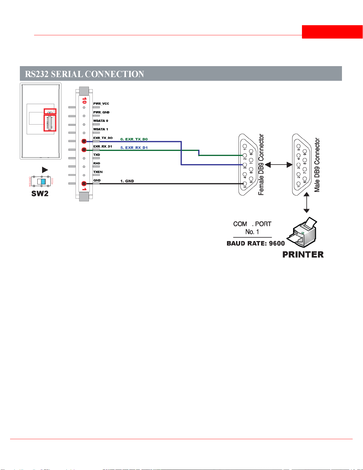
12.8 Serial Printer
INSTALLATION GUIDE 70
© 2012 IDTi

BSC-101 V.4 Operations Manual71
12.9 Installation Diagram
© 2012 IDTi

Index
72
Index
- A -
Address 36
Alarm Setup 59
Anti Pass Back 39
Asia 40
Attendance 44
auxiliary relays 56
- B -
baud rate 38
Buzzer 59
- C -
Com. Speed 38
Communication Password 36
Conceal PIN 43
Custom Display 41
- F -
facility code 36
firmware 29
Function 56
function keys 44
- I -
ID Option 23
Input Type 56
- L -
LCD Light 42
lock time 35
Lockdown 44
- N -
Network ID 36
Normally Open 39
- D -
Date Format 40
Delete All User 32
Delete Single User 32
display IN or OUT 44
Door Relay 39
Duress 40
- E -
Edit User Card 20
Edit User ID 20
Edit User Level 21
Edit User Name 21
Enroll Block of Card 16
Enroll Card 15
Europe 40
Event Reset 37
Events 29
external alarm system 44
- O -
Operating BioScan 8
Operating Funtion Key 10
Operating Mode 34
- R -
Re-Lock Time 35
- S -
Setting Operating Mode 35
Site Code 36
System Reset 37
- T -
Time 34
Two Man 24, 39
© 2012 IDTi

BSC-101 V.4 Operations Manual73
- U -
unique identification code 36
USA 40
User Antipass 23
User List 28
© 2012 IDTi
 Loading...