

Page 1

Reference Manual
Page 2

113501
The product, and product features as described in this document are subject to change
without notice and does not represent a commitment on the part of IDENTEC
Solutions, Inc. The software described in this document is furnished under a license
agreement.
Limitation of Liability. In no event shall Identec or its suppliers be liable for any
damages whatsoever, including damages for loss of business profits, business
interruption, loss of business information or any other loss arising out of the use of or
inability to use this product, or the provision or failure to provide support services.
IDENTEC’s entire liability shall be limited to the replacement cost of this product.
NOTE : This e quipme nt ha s be e n tes te d and fo und to c o mply with the
limits for a Class A digital device, pursuant to Part 15 of the FCC Rules.
These limits are designed to provide reasonable protection against
harmful interference when the equipment is operated in a commercial
env i ronment. Thi s e quipme n t ge ne rate s , uses, a nd c an radiate radio
frequency energ y and, if not i ns tal le d a nd us e d in a c c ordanc e w ith the
instruction manual, may cause harmful interference to radio
communication. Operation of this e quipment in a residential area is like ly
to cause harmful interference in which ca s e the user will be required to
correct the interference at his own expense.
Warning: Changes or modifications to this unit not expressly approved by the party
responsible for compliance could void the user’s authority to operate the equipment.
FCC ID: OO3-ILR-IPORT
CANADA: 35381032062A
MODEL: i-PORT
TYPE: II/S
This Class A digital apparatus meets all requirements of the Canadian InterferenceCausing Equipment Regulations.
Cet appareil numérique de la classe A respecte toutes les exigencies du Règlement sur
le matériel brouilleur du Canada.
This User Manual is copyright © 2000 by IDENTEC Solutions, Inc.
2
Page 3

113501
Contents
CONTENTS...................................................................................................................3
1 INTRODUCTION................................................................................................5
1.1 G
1.2 P
3.1 O
3.2 O
3.3 T
3.3.1 RS232 9 Pin Interface Connection for Test Serial Port...........9
3.4 B
3.4.1 RS232 9 Pin Interface Connection for Bar Code.....................9
3.4.2 RS485 9 Pin Interface Connection.........................................10
3.5 A
ENERAL
RODUCT DESCRIPTION
.................................................................................................................5
..........................................................................................5
2 I-PORT TERMINAL BLOCKS — BRIEF DESCRIPTION...........................6
3 SYSTEM INPUTS AND OUTPUTS...................................................................8
PTO COUPLED INPUTS
PTO COUPLED USER OUTPUTS
EST SERIAL PORT
AR CODE INTERFACE
NTENNA MULTIPLEXER OUTPUTS
(INPUT 1…4)...................................................................9
(RLY 1A, 1B…4A, 4B) ........................................9
..................................................................................................9
............................................................................................9
.......................................................................10
4 SMA COA X CONN ECTO RS (SO C KET S ).....................................................10
5 SELECTOR SLIDE SWITCHES.....................................................................11
6 I-PORT PC CARDS...........................................................................................11
6.1 T
6.2 T
6.3 T
6.4 U
HE
HE I-FLASH MEMORY CARD
HE
SER INTERFACE CARD
ARD
ILR-C
ATA F
.....................................................................................................12
LASH STORAGE CARD
................................................................................13
.........................................................................13
.........................................................................................13
6.4.1 Ethernet Card.........................................................................13
6.4.2 Modem PC Card (optional) ...................................................14
6.4.3 RF Modem Card (optional) ...................................................14
7 I-PORT ANNUNCIATOR LEDS .....................................................................14
8 RESET BUTTON...............................................................................................17
9 EXTERNAL POWER SUPPLY REQUIREMENTS.....................................17
9.1.1 The Power Supply Basic Requirements .................................17
9.1.2 Backup Battery.......................................................................18
10 LCD OPTION................................................................................................18
11 INSTAL LA TIO N AN D WIR ING PROC ED URE ......................................18
11.1 P
11.2 E
11.3 I
11.4 C
HYSICAL INSTALLATION
LECTRICAL INSTALLATION
NITIAL POWER UP
ONFIGURATION OF THE I
................................................................................................20
......................................................................................19
..................................................................................19
-PORT
FOR
LANS........................................................20
3
Page 4

113501
12 I-PORT ANTENNAS ....................................................................................21
13 I-Q TAGS .......................................................................................................23
14 SOFTWARE...................................................................................................24
15 ILR EXPLORER DEMONSTRATION/TESTING SOFTWARE...........25
16 PRODUCT SUPPORT..................................................................................25
16.1 TO R
EACH
IDENTEC S
UPPORT
............................................................................26
16.1.1 Online support .......................................................................26
16.1.2 E-mail support .......................................................................26
16.1.3 Telephone and Fax Support...................................................26
16.1.4 Support numbers....................................................................26
16.1.5 Order Desk.............................................................................26
16.1.6 Warranty Service ...................................................................26
16.1.7 Additional Tools and Training...............................................26
17 APPENDIX.....................................................................................................27
17.1
I
-PORT P
RINTED CIRCUIT BOARDS
......................................................................27
17.1.1 The Power Supply Board .......................................................27
17.1.2 The Computer Board..............................................................27
17.1.3 The LED Board......................................................................27
4
Page 5

113501
1 Introduction
1.1 General
This document provides information for the installation and operation
of the IDENTEC i-PORT fixed RFID interrogator.
Other documentation that may be applicable includes the
Developers Guide To Programming For The ILR Library
User Manual
i-Q Tag Technical Sheet.
the
ILR-CARD Installation & Configuration Sheet
, the
Application
, the
1.2 Product Description
The i-PORT is a 100 MHz computer with an installed ILR Card for
communicating with the i-Q series of active tags. The i-PORT is
configured to provide application developers with the necessary
connections and controls for advanced automatic data capture
applications using ILR technology.
®
The operating system in the i-PORT is Windows CE
management and provides the interface to the ILR-CARD and other
user optional PC Cards in the i-PORT. Application programs developed
to run on the i-PORT are written using high-level application
languages. Programs use calls to the IDENTEC i-PORT software
library to access the RF functions and other controls on the i-PORT. For
additional information on programming the i-PORT please refer to the
document;
ILR Library
Application Developers Guide To Programming For The
.
that provides data
i-COM
, and
The i-PORT enclosure is an IP65 (or is it P66 / NEMA 4
(CSA/UL/VDE)) rated steel case with a glass panel for viewing the
status LEDs. An optional LCD is also available for the i-PORT that
replaces the glass panel with a 480 X 320 backlit monochrome touch
screen to allow data input and application commands to be entered
directly at the i-PORT.
Cable entry for wiring the i-PORT is through five compression seal
cable clamps at the base of the enclosure. The access door to the iPORT is equipped with a gasket seal and is closed and opened using a
special tool that is included.
5
Page 6
113501
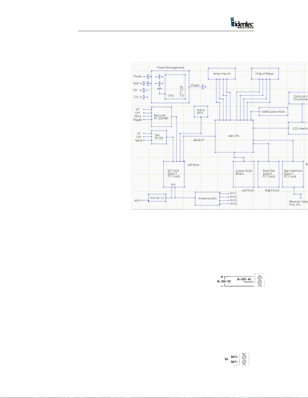
p
i-P ORT Block Diagram
2 i-PORT
Termi nal
Blocks —
Brief
Description
The i-PORT
terminal block
lay out is
depicted in
figure 2. The
function of each
of the connectors
is described
below.
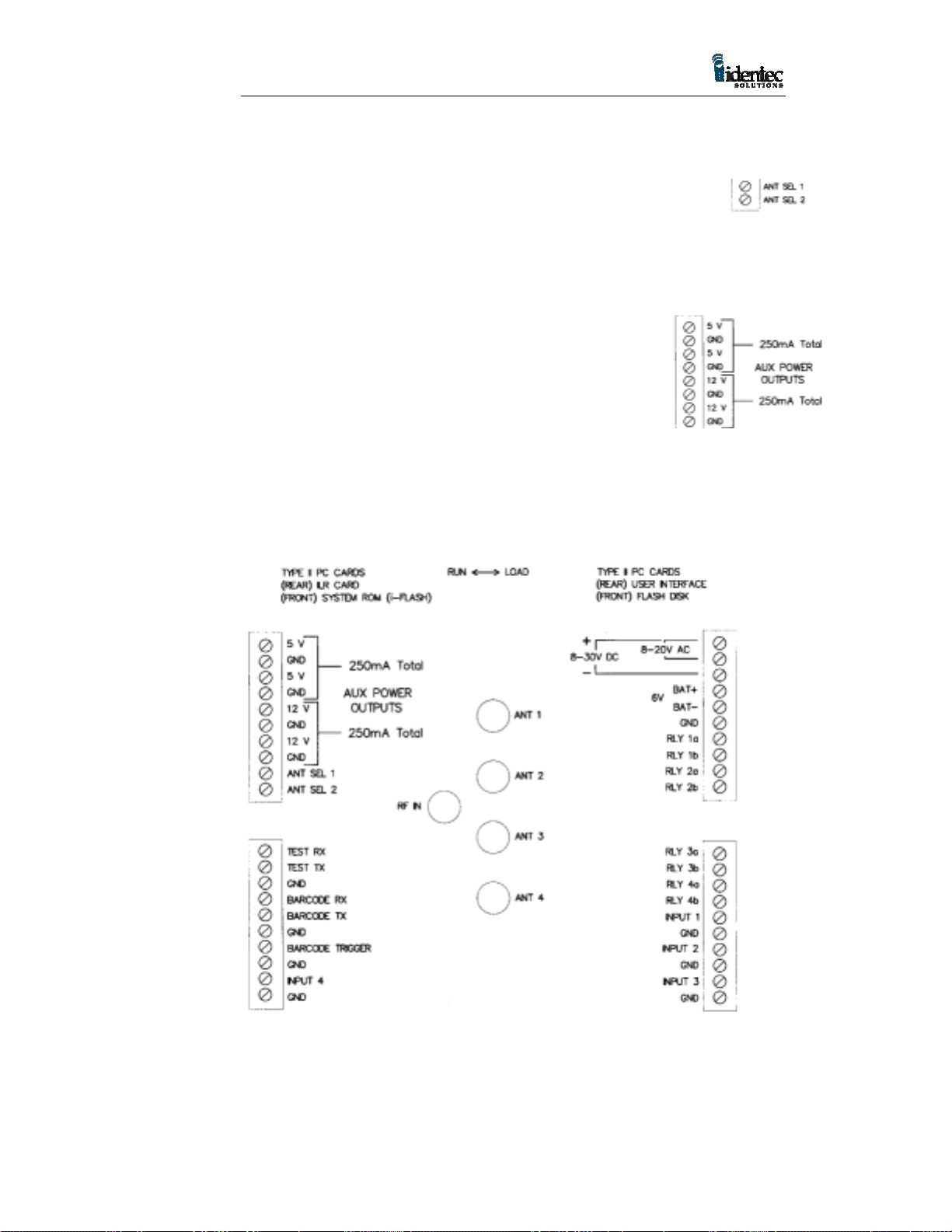
Tw o terminals
Tw o terminals
os. & neg.
Caution: Never
connect or
Figure 1
disconnect any cable or remove or install a PC Card while the i-PORT
is running.
8 – 20V AC Input power supply for i-PORT, to be used when only
an AC power source is available. Range min. 8V to
max.20V AC. Recommended range
is 12V to 18V AC.
8 – 30V DC Input power supply for i-PORT, to
be used when only a DC power source is available.
Range min. 8V to max. 30V DC. Recommended range
is 12V to 24V DC.
Note: Either DC or AC power can be applied, but never both at the
same time. Obey terminal polarity for any DC source. Caution must be
taken to insure only the first and third block connectors are used for
DC and only the first and second block connectors are used for AC.
6V BAT+ Positive terminal of 6V backup battery.
6
Page 7

113501
6V BAT- Negative terminal of 6V backup battery. This terminal
is connected to system ground
Note: The battery voltage must be 6V. The battery should be either a
Sealed Lead Acid or a Gel Cell. The recommended minimum capacity
for the battery is 2.6 Ah. This is sufficient to provide back up power for
short power outages lasting a few minutes.
Total of 12
GND termina ls
Terminal pair
Terminal pair
Terminal pair
Terminal pair
Total of 4
GND System ground.
RLY 1a, 1b User relay contacts enabled by software.
Note: Contact rating for these solid-state relays is max. current 130mA,
max. load voltage 300V
, max. power dissipation 500mW. The tighter
rms
of any restrictions applies. Typical ON-resistance is 25 static, 12 at
full load. These ratings apply to all relay contacts.
RLY 2a, 2b User relay contacts enabled by software.
RLY 3a, 3b User relay contacts enabled by software.
RLY 4a, 4b User relay contacts enabled by software.
INPUT 1, 2, 3, 4 Opto-coupled user definable trigger inputs, pull to
ground to activate (short to GND terminal).
BARCODE Enables signal input from Barcode Reading Device via
TRIGGER the serial connection. Pull to ground potential to
activate (short to GND terminal).
BARCODE TX Serial output to Barcode Reading Device.
BARCODE RX Serial input to Barcode Reading Device.
Note: Depending on top slide switch setting, the serial line for the bar
code ports will be compliant to either RS-232 or RS-485 standard.
These terminals can be used to connect other serial devices.
TEST TX Serial test output.
TEST RX Serial test input.
Note: The serial line for the test connection is always RS-232.
7
Page 8
113501
Tw o terminals,
Tw o terminals,
Tw o terminals,
ANT SEL 1, 2 Software controlled output of two antenna
sele ct or control signals for external antenna
multiplexer with maximum four antenna
ports.
12V Auxiliary power outputs, for user selected devices.
Maximum combined load for the two 12 V terminals is
250mA.
5V Auxiliary power outputs, for user
sele cted devices. Maximum
combined load for the two 5 V
terminals is 250mA.
Note: The auxiliary power outputs are always on and are not software
controllable.
i-PORT Terminal Block Layout
Figure 2
3 System Inputs and Outputs
This chapter describes in greater detail the inputs and outputs
connections on the i-PORT terminal blocks.
8
Page 9

113501
3.1 Opto Coupled Inputs (INPUT 1…4)
The opto-coupled inputs are tied to 5V via the internal opto-isolator, a
limiting resistor and an input status LED. Left open, no current flows
and the status LED is off. If the input is tied to ground, directly through
dry relay contacts, or via a resistor of up to 100 ohms, the LED will
light and the ILR CARD will see the input as ‘pulled low’. Resistance
of greater than 100 ohms may cause the LED to glow but may be
insufficient for the input to be seen as ‘pulled low’.
3.2 Opto Coupled User Outputs (RLY 1a, 1b…4a, 4b)
The four relay outputs are opto-isolated solid state relays offering
5,000V isolation with a current rating of 130mA at 350V. The contacts
are normally open, indicated by the corresponding status LED being
unlit. The status LED lights when the relay contacts ‘close’. Both
contacts are electrically isolated from other system voltages and float.
3.3 Test Serial Port
The test serial port is set to 9600 baud and is a 3 wire port (TX, RX and
GND). It offers 15KV isolation and is true RS232. Data to and from
this port are relayed by the ILR CARD to the host computer.
3.3.1 RS232 9 Pin Interface Connection for Test Serial Port
Signal Name Pin
TEST TX 2
TEST RX 3
GND 5
1 2 3 4 5
6 7 8 9
3.4 Bar Code Interface
The Bar Code serial port is set to 9600 baud and is a 4 wire port (TX,
RX, Trigger and GND). It offers 15KV isolation and is true RS232.
Data to and from this port are relayed to the host computer by the ILR
CARD. This connection is intended for a tethered bar code scanner with
the power provided by one of the 5V auxiliary outputs.
This input can be switched from RS232 to RS485 if long
communication range is needed. This connection can be used to connect
any serial input device. The slide switch for RS232 or RS485 is at the
top of the i-PORT, and is described in section
5 Selector Slide Switches
.
3.4.1 RS232 9 Pin Interface Connection for Bar Code
9
Page 10

113501
Signal Name Pin
BAR CODE TX 2
BAR CODE RX 3
GND 5
BAR CODE TRIGGER 6
3.4.2 RS485 9 Pin Interface Connection
Signal Name Pin Function
BAR CODE TX 2 Data A
BAR CODE RX 3 Data B
GND 5
BAR CODE TRIGGER 6
3.5 Antenna Multiplexer Outputs
These are the ANT SEL 1 and ANT SEL 2 signals and are intended for
connecting an external antenna multiplexer. The external multiplexer
requires only a single coax cable to run from the MMCX antenna
connection on the ILR-CARD to the multiplexer. In installations where
the i-PORT cannot be installed in close proximity to the antenna
locations the use of an external multiplexer can reduce the coax wiring
requirements.
Note: The total length of coax cabling used to connect an antenna can
affect signal strength from the antenna to the i-PORT. A signal loss
more than 6 dB will reduce read range.
The Antenna Multiplexer Outputs are software controlled digital
outputs, in binary form offering one of four combinations with the two
signals. These are ESD protected, and can drive up to 4mA, within the
voltage range of 0 to 3.3V. They should not be connected to circuits
that may pull the outputs to voltages higher than 3.3V.
4 SMA Coax Connectors (Sockets)
The RF antenna connector on the ILR CARD is a miniature
MMCX connector. This connects to the SMA input connector on
the antenna multiplexer using the 3.5 inch coax pigtail. The
output SMA connectors on the multiplexer connect up to four
antennas to the i-PORT. The ANT 1 to ANT 4 status LEDs
indicate the active antenna. The illuminated LED will change as
the multiplexer sequences through the antennas, with the LED
for the last antenna sequenced remaining illuminated.
10
Page 11

113501
RF IN Takes a 3.5 inch coax pigtail (part # CAB001) to
connect the ‘RF IN’ port to the ILR-Card RF connector
ANT 1, 2, 3, 4 Independent antenna ports for one to four external
antennas
Note: The address sequencing for the antenna multiplexer is software
controlled.
5 Selector Slide Switches
There are two selector slide switches on the i-PORT. One slide switch
is located on the topside of the LED board, and is used to switch the bar
code connection between RS 232 and RS 485. This switch setting must
comply with the serial interface of the connected device.
The other slide switch is located between the PC Card slots. The setting
options for this switch are RUN and LOAD. This switch must be set to
RUN during operation of the i-PORT. The LOAD position is used to
transfer a compressed binary image file from a Master Image PC Card
to the i-Flash Memory Card. This procedure should only be done by
IDENTEC certified advanced programmers.
6 i-PORT PC Cards
The i-PORT has four PC Card slots on the computer board. The slots
are for the ILR-Card, the i-Flash Memory Card, the ATA Flash Storage
Card, and the User Interface Card.
Note: Each of the four PC Cards described below has its own
designated PCMCIA slot on the Computer Board and is not
interchangeable with the others. Before removing or replacing any of
the PC Cards the power to the i-PORT must be turned off.
Note: All PC Cards used in the i-PORT must be 5 volt.
11
Page 12

113501
6.1 The ILR-Card
The ILR-CARD is the rear PC Card on the left side. It has two I/O
connectors on the exposed end, the MMCX Antenna connector, and a
15-pin programming connector. The programming connector is used by
IDENTEC to configure the ILR-CARD. There are also three LEDs on
the exposed end of the ILR-CARD to indicate transmit, receive and RF
carrier detect.
The ILR-CARD contains a Configurable Processor System Unit
(CPSU) with internal non-volatile memory. The CPSU chip is
programmed by IDENTEC and contains the firmware code to run the iPORT. The CPSU also contains a Real Time Clock, with a separate
power supply that will power the clock for over 24 hours.
The ILR-CARD contains the RF circuitry for the wireless
communication with IDENTEC tags. The application software running
on the i-PORT, or other host computer, sends commands to the CPSU
to communicate with the tags. The CPSU on the ILR-CARD controls
the function of all LED’s on the LED Board, as well as the Piezo buzzer
on the Power Supply Board. It also manages the 6V backup battery
charge function. The normal mode (power-up and standby) of the ILRCARD is ‘Receive Mode’, as opposed to the time-limited ‘Transmit
Mode’, which has to be initiated by the controlling host computer.
Note: The ILR-CARD used in the i-PORT is in a PC Card Type II
housing but it is not configured with a PCMCIA interface. The ILRCARD in the i-PORT has a serial interface and can only be used in the
assigned card slot on the i-PORT. Each ILR-CARD is marked with an
12
Page 13

113501
interface type, either PCMCIA or serial. Do not use an ILR-CARD with
a PCMCIA interface in the i-PORT.
6.2 The i-Flash Memory Card
This card is a linear Flash memory device with special non-volatile
memory. The standard card supplied with the i-PORT is 4MB, but
optional upgrades are available for 8MB and 16MB of memory. The iFlash Card contains compressed binary image files used by the
operating system running on the Computer Board.
Note: The i-Flash Card is a custom linear memory card and cannot be
replaced by commercial ATA Flash Storage Cards.
6.3 The ATA Flash Storage Card
The i-PORT file system uses a Type II PC Card format ATA flash
storage card. The standard card provided with the i-PORT is 8MB, but
larger cards of 16MB or 32MB are supported. The ATA flash storage
card carries files for the operating system, among them the previously
programmed IP Address. If replacing this card an IP Address has to be
programmed in to the new card before the i-PORT can connect to a
network.
Note: The i-Flash card is programmed with a default IP Address. If the
ATA Flash Storage Card is replaced without programming in the new
address the default will be used, (see section
Procedures
for IP Address programming instructions).
10 Installation and Wiring
6.4 User Inte rfa c e Card
The rear right PC Card socket on the i-PORT is for the user interface
card. This can be any Type II PC Card with a Windows CE
Note: To remove the PC Cards in the i-PORT the terminal blocks must
first be removed. Disconnect the power, or remove the power
connection terminal block first.
6.4.1 Ethernet Card
This Type II PC Card is the standard card provided with an i-PORT for
the user interface. A standard network adapter plugs into this 10BaseT
LAN card to link it to an industry standard, RJ-45 CAT 5 twisted-pair
network cable connector.
®
driver.
13
Page 14

113501
6.4.2 Modem PC Card (optional)
For dial-up networking a modem card can be inserted in the User
Interface PC Card slot on the i-PORT. This card would be used instead
of the Ethernet Card
6.4.3 RF Modem Card (optional)
For wireless networking a RF modem can be used with the i-PORT. An
IEEE 802.11 (Frequency Hopping?) card is recommended. If using an
RF modem it is necessary to use an external antenna because of the iPORT metal enclosure.
Note: to maintain the IP65 industrial rating all cabling must be through
the five compression cable clamps at the bottom of the i-PORT. Not all
connector types will pass through these clamps. It may be necessary to
terminate cabling after it is pulled into the i-PORT housing.
7 i-PORT Annunciator LEDs
The annunciator LEDs are for testing, and to monitor i-PORT functions.
For a layout see figure 3.
14
Page 15

113501
i-PORT Annunciator LED Board
Figure 3
The left side single row of LEDs in figure 3are described below.
INPUT POWER Indicates the presence of external supply power for
the i- PORT.
EXT. BATTERY If the external power supply fails, and the 6V backup
battery takes over this LED will be lit. Only one of the
power source indicator LEDs, the INPUT POWER or
the EXT. BATTERY, will be lit at anyone time.
30V Internal 30V s upply present .
12V Internal 12V s upply present .
5V Internal 5V supply present.
3.3V Internal 3.3V supply present.
15
Page 16

113501
Note: The internal voltage LEDs will all be illuminated when input
power is applied. There are no LEDs for the auxiliary power outputs.
EXT. BATTERY Indicates the 6V backup battery is being charged.
CHARGING
RSSI Receive Signal Strength Indicator (currently not used).
TRIGGER Displays activity on the BARCODE TRIGGER input.
LCD HEATER Displays heater element on (when equipped).
The right side Annunciator LEDs are organized and labeled in pairs.
For the label “RFID RX / TX”, the RX is the left LED and the TX is the
right LED.
RFID RX Lights whenever the ILR-CARD receives valid RFID
data from tags.
RFID TX Lights whenever the ILR-CARD transmits RFID data
to tags.
HOST RX Lights when i-PORT receives data or commands from
controlling host computer (i.e. via LAN connection).
HOST TX Lights when i-PORT transmits data t o controlling host
computer.
TEST RX Shows activity on serial transmit line (RS-232) for
testing.
TEST TX Shows activity on serial receive line (RS-232) for
testing.
BARCODE RX Indicates the input of data from a barcode reader or
other ser ial input device over the ser ial terminal (RS-
232 or RS-485).
BARCODE TX Indicates the output of commands to a barcode reader
or other serial device over the serial terminal (RS-232
or RS-485).
INPUT 1 Lights when terminal INPUT 1 is active (shorted to
ground).
INPUT 2 Lights when terminal INPUT 2 is active (shorted to
ground).
16
Page 17

113501
INPUT 3 Lights when terminal INPUT 3 is active (shorted to
ground).
INPUT 4 Lights when terminal INPUT 4 is active (shorted to
ground).
OUTPUT 1 Lights when user relay contacts RLY 1a, 1b are
closed.
OUTPUT 2 Lights when user relay contacts RLY 2a, 2b are
closed.
OUTPUT 3 Lights when user relay contacts RLY 3a, 3b are
closed.
OUTPUT 4 Lights when user relay contacts RLY 4a, 4b are
closed.
ANT 1, 2, 3, 4 Displays selector status of antenna multiplexer.
8 Reset Button
Located at the bottom of the annunciator LED panel is the system
master reset button. Depressing this button will cause a warm reboot
that will restart Windows CE ® and reset the ILR card without
interrupting the power supply.
9 External Power Supply Requirements
Operation of the i-PORT requires an AC or DC power supply.
IDENTEC strongly recommends the use of a linear (transformer) power
supply with or without built-in rectifier. Suitable industrial transformers
are widely available, or can be ordered from IDENTEC.
The use of a switching power supply is not recommended because it
may not be able to provide a sufficient initial inrush current for power
up. The i-PORT consumes about 6 watts under normal use,
consumption increases by 5 watts for the optional LCD heater and by
another 3 to 5 watts when charging the backup battery.
9.1.1 The Power Supply Basic Requirements
For a DC power supply the output voltage must be between 8V and
30V DC. The recommended power range is 12V to 24V DC. Output
power rating should be no less than 12W DC.
17
Page 18

113501
For an AC power supply the output voltage must be between 8V and
20V AC. The recommended power range is 12V to 18V AC. Output
power rating should be no less than 14VA AC.
The suitability of the power supply output can also be determined with
an output current rating of 1A minimum at 12V, or a current rating of
1.5A minimum below 12V.
Example:
The output current of the transformer must be capable of no less than
1000mA for a 12V AC/DC linear supply.
9.1.2 Backup Battery
A 6V backup battery, usually a lead acid gel cell, can be connected
directly to the backup battery terminals. An inline, slow-acting fuse of 3
Amps rating is highly recommended. The battery is charged at 180mA
until fully charged and then will continue to be trickle charged. The
battery supplies power to the i-PORT when the input power drops
below the battery terminal voltage.
10 LCD Op tion
The LCD is a factory-installed touch screen to allow data input and
systems functions to be controlled directly at the i-PORT. The LCD
replaces the clear glass panel on the front of the i-PORT and is
connected to the computer board with a flex cable. The LCD screen
provides the following features:
•
480 X 320 VGA resolution
•
Monochrome, 4 shades of gray
•
Permanent electro luminescent backlight
•
Auto temperature sensing heater to extend useful range
•
Auto temperature compensating contrast
•
Protective film overlays available
11 Inst al lation and Wiring Procedur e
This chapter describes the installation and wiring procedure for an iPORT in a fixed location. If installing the i-PORT on mobile
equipment, such as a forklift, see the IDENTEC bulletin
PORT as a Mobile Interrogator
.
Using the i-
18
Page 19

Environment Range
y
g
Physical
Dimensions 11.75" x 7.75" x 3.2" (30 x 20 x 8 cm)
113501
Weight 7.5 lbs (3.4 kg)
Operational
Temperature 32° F to 158° F (0° C to 70° C)
Humidity 90% non-condensing
Storage
Temperature -40° F to 185° F (-40° C to 85° C)
Humidit
90% non-condensin
Impor tan t Note to Insta ll er:
This device requires professional installation by a certified
electronics technician or electrical engineer, following each and all
procedures of the installation manual. This device is only legal to
operate in conjunction with the antenna type approved by FCC and
Industry Canada.
The installer is taking legal responsibility that all steps outlined in
the IDENTEC installation manual have been executed properly,
and that the installed device is complying with FCC Part 15 and the
limits for a ‘Class A Digital Device’, as defined by Industry
Canada.
11.1 Physical Installation
The rugged i-PORT enamel steel enclosure is intended to be wallmounted with four adequately sized screws. Before mounting the iPORT to the wall the four plastic caps need to be removed from the rear
of the enclosure.
The i-PORT enclosure is rated IP65 (P66?) for protection against water
spray. The enclosure is suitable for industrial installation, but is not
intended to be use in an exterior location. If it is necessary to install the
i-PORT in an exterior location it must have additional shielding against
the weather.
The operational temperature range for the i-PORT is between 32° F and
70° F. If the temperature could vary out of this range additional
precaution must be taken. In the case of cold temperatures a heat
element can be installed in the i-PORT.
11.2 E l ectrica l In sta ll ati on
Wherever available, a ground wire (Protection Earth) should be
connected to the internal case grounding-stud. This is a
recommendation only and is not essential for i-PORT functionality. The
i-PORT is a low voltage device with no line voltage required.
For a description of the electrical connections refer to Section 2
Terminal Blocks — Brief Description,
Outputs
. For the specifications on the power supply see Section 8
External Power Supply Requirements
and Section 3
.
System Inputs and
i-PORT
19
Page 20

113501
The four terminal blocks in the i-PORT can be removed to make
connecting wires easier. If there is no inline power switch being used
with the i-PORT the power connection block should be inserted last for
power up. This must be done after all other connections have been
made and the other terminal blocks properly installed.
Note: All ‘GND’ terminals are directly connected to system ground, so
is the negative battery terminal ‘BAT-‘.
Generally, any type of cable can be used that fits through the five
compression clamps. From a practical consideration, the wire gauge for
control signal inputs and outputs should be AWG 18 or 20. Power wires
and ground should be AWG 18.
Note: The Ethernet CAT 5 cable will have to be terminated with an RJ45 connector after feeding it through one of the five compression
clamps.
Note: The Ethernet cable needs to run through the Ferrite Box Snap to
suppress RF noise from the Ethernet Card. The cable should be
wrapped around the Ferrite Box so the cable passes through the box
twice. The installed Ferrite box should be attached to the Ethernet
cable inside the i-PORT, and placed in the bottom left corner of the
enclosure.
11.3 Initial Power Up
When the i-PORT is first installed connect the input power source for at
least one minute then reset the i-PORT or cycle power and commence
normal operation. This ensures adequate charge up time for the internal
Real Time Clock supply voltage. This procedure has to be repeated
whenever the i-PORT had been disconnected from its input power
source for more than 24 hours.
11.4 Configuration of the i-PORT for LANs
When using the i-PORT as a client on an Ethernet network the start-up
IP address will be the default address stored on the ATA Flash Storage
Card. To change the address this card can be removed from the i-PORT
and inserted into a computer with a PC Card slot. The card can then be
accessed as a drive on the computer.
Note: for information on accessing a PC Card as a drive on the
computer refer to your Windows® user documentation.
20
Page 21

113501
With the Flash Storage Card in a Windows® computer use a text editor
to open the file “ipsettings”. This data file is ASCII format. The values
in this file must be listed as follows:
IPAddress
Subnetmask
DefaultGateway
Blank Line
Before saving make sure you hit enter after DefaultGateway.
“ipsettings”
192.168.1.123
255.255.255.0
0.0.0.0
! Blank Line "
Figure 4
Every time the i-PORT is started the RestoreReg file will be loaded.
This program reads applicable keys from the i-PORT registry and
compares the existing default key values with the values stored in the
“ipsettings” file. Any changes made in the “ipsettings” file will be used
by the system. These changes are stored in the i-PORT RAM and are
updated from the “ipsettings” file anytime the i-PORT is rebooted. If a
new ATA Flash Storage Card is used in the i-PORT the “ipsettings” file
must be updated.
12 i-POR T Antennas
Antennas for use with the i-PORT are required to have a gain equal to
or less than 5dBic. It is recommended that the antenna polarization
should be elliptical or circular, although in applications where the
orientation of the tag is in a consistent and known position linearly
polarized antennas can also be used.
The i-A9185 antenna typically supplied with the i-PORT is an
elliptically polarized patch type antenna, providing a superior radiation
pattern for interior or exterior use.
21
Page 22

113501
Figure 5
The i-PORT can connect up to four antennas using either the internal
multiplexer or an external multiplexer. The cable to connect the ILRCARD to the internal multiplexer is supplied with the i-PORT. To
connect an external multiplexer the coax cable to the ILR-CARD can
use a SMA connector with the supplied antenna pigtail as a connector
converter, or the coax will require an MMCX male end to connect
directly to the ILR-CARD.
For any antenna connection the maximum cable length allowed can
produce a decibel loss no greater than 6dB. Each coax cable type and
gauge will have different loss characteristics and the installer should
contact the cable supplier to determine the suitability any cable for their
application.
In most locations it is probable that null spots will exist in the coverage
of any single antenna. If a tag is in a null spot even though it is within
range of an antenna it will not be interrogated. This is typically not a
problem when tags are moving through a read zone, but if the tags must
be interrogated while stationary it will be necessary to create
redundancy in the read zone. Any stationary tag that must be
interrogated should be within range of at least two antennas.
22
Page 23

113501
13 i-Q Tags
IDENTEC i-Q tags are available in a number of configurations to match
the tag with the application. Tags of different types can be mixed in a
single system and can be interrogated simultaneously by an i-PORT.
Tags are available as read only, read/write with 8 KB of memory, and a
read/write tag with and optional temperature monitor. Tag memory is
expandable to 32KB.
Table 1
F EATURES
READ RANGE > THAN
100 FE E T
8 KBYTES OF
MEMORY
BROA DCAST
CAPABILITY
ANTI – COLLISION
ALGORI THM
5 YEAR BATTERY LIFE YES YES YES
TEMPERATURE
MONITORI NG
OPERATES IN HARSH
ENVIRONMENTS
i - QR i – Q8 i – Q 8T
YES YES YES
YES YES
YES YES YES
YES YES YES
YES
YES YES YES
All i-Q tags are active and include an RF transmitter, RF receiver, and a
microprocessor. The communication range between a tag and an iA9185 antenna connected to an i-PORT interrogator will be up to 30
meters under typical conditions. Read range will vary depending on the
local conditions, and it is important to test tag read performance under a
variety of probable scenarios.
For more information see the
i-Q Tag Technical Sheet.
23
Page 24

113501
14 So ftware
This chapter provides basic information on how to control the operation
of the i-PORT. For more detailed information please see the
Application Developers Guide To Programming For The ILR Library.
ILR technology requires an application program to provide end-user
functions, this level of software is provided by the System Integrator.
To facilitate the development of user specific applications, IDENTEC
has extended the Windows API (Application Program Interface) to
include easy access to ILR functions using C program calls.
IDENTEC does provide a demonstration package to allow the installer
to configure and to test the basic functions of the i-PORT. This software
is covered in Section 14
To allow maximum flexibility in interrogating tags, scanning barcodes,
allowing user data entry, providing user information, formatting and
sorting data, and data transfer to tags and over a network, the i-PORT
functions under the direction of a control program. This control
program customizes the i-PORT to do the required task. It is generated
by a menu-driven Windows application that allows the user to specify
how the system will operate.
ILR Explorer Demonstration/Testing Software.
This is a simple but very powerful feature of the IDENTEC ILR
system. It allows an i-PORT to perform similar tasks in very different
ways from completely automated tag interrogation and reporting to
automated assistance in process operations. The data source for various
fields can be specified, e.g. tag ID, tag file, barcode scan, user-keyed
input, or a digital input. A sequence of events can be specified to gather
data, format data in a specific way, and/or communicate data to a
specific location.
File I/O system on the i-PORT has the usual features such as Create,
Delete, Read, Write, Directory, and Attributes. The tag file system
supports any data format that will fit in the space available. Flat files
are supported with fields delimited by column or delimiter character,
and records delimited by linefeed.
Note:
Microsoft
®
Windows® CE Toolkit for Visual C++
make applications run on
Windows® CE
operating system for x86
is required to
microprocessors that is used on the i-PORT.
24
Page 25

113501
15 ILR Explorer Demonst ration/Testing S oftware
ILR Explorer runs on a host Computer to demonstrate and test the
capabilities of an i-PORT. The system requirements are a 486 or higher
CPU, running Windows 95 or newer, with a minimum of 120MB of
hard drive space.
The i-PORT is equipped with an Ethernet card for connection to a
LAN, or it can be connected directly to an Ethernet equipped computer
by using a mirrored Cat. 5 cable. The Ethernet card included with the iPORT is a 10BaseT connection.
ILR Explorer allows the user to communicate with all i-Q type tags
within range of the antenna, write and read data files to and from tags,
set various properties of the i-PORT and tags, read temperature log
information from a tag and create files to be stored on the tag.
15.1.1.1 Installing ILR Explorer
On the installation disk included is an Install Shield setup file. Please
run the file “setup.exe” to start the installation process.
15.1.1.2 Running IL R Explor e r
To start ILR Explores double click the icon on your desktop, or in the
folder you selected during installation, or select “ILR Explorer” from
the “Star t” Menu.
For more information on the ILR Explorer see the “README.TXT”
file included on the ILR Explore disk.
16 Product Support
Technical support for IDENTEC ILR products is available by e-mail,
online and by telephone or fax. Full support is provided to Authorized
Systems Integrators who have completed the technical training sessions
and are certified ILR technicians.
Additional training and product support is available from IDENTEC
under a support agreement. Field Support is also available on a contract
basis. Support can be provided for site surveys, and for product
installation and testing. Contact your account manager for full details.
25
Page 26

113501
16.1 To Reach IDENTEC Support
16.1.1 Online support
Technical support is available online to all IDENTEC Authorized
System Integrators. Answers to many common questions and problems
are included in our searchable database at www.IDENTEC.com\faq.htm
this database can be made accessible to any product user.
16.1.2 E-mail support
When sending an e-mail include your name, company, telephone and
fax numbers along with your question or problem.
In North America support@IDENTEC.com
In Europe and the UK support@IDENTEC.au
16.1.3 Telephone and Fax Support
Telephone assistance in North America is available from 8:30 to 5:30
Pacific time, Monday through Friday, Canadian holidays not included. .
16.1.4 Support numbers
North America
Tel: (250) 860-6567
Fax: (250) 860-6541
Toll Free Phone 1-877-IDENTEC
16.1.5 Order Desk
To order products contact the order desk by phone or fax
North America
Tel: (250) 860-6567
Fax: (250) 860-6541
Toll Free Phone 1-877-IDENTEC
16.1.6 Warranty Service
For warranty service contact the warranty department within your
region to get a warranty claim number. All products returned for
warrantee service must include a warranty service number for prompt
processing.
In North America phone (250) 860-6567
16.1.7 Additional Tools and Training
Support is provided only to trained systems integrators. IDENTEC
provides training in ILR technology with the purchase of a development
kit. To have additional employees or third party consultants certified to
receive full access to product support IDENTEC offers certification
training.
26
Page 27

113501
17 Appendix
17.1 i-PORT Printed Circuit Boards
The i-PORT consists of three PCBs, the Power Supply Board, the
Computer Board, and the LED Board.
17.1.1 The Power Supply Board
This circuit board incorporates the following functional groups and
components:
Bridge Rectifier for AC Input Power
Se lf-resetting Fuse
30V Switching Power Supply (internal)
12V Switching Power Supply (internal & auxiliary user access)
5V Switching Power Supply (internal & auxiliary user access)
3.3V Switching Power Supply (internal)
6V Battery Charger Switching Power Supply (external)
Real Time Clock Backup Voltage Supply (internal)
Quadruple Antenna Multiplexer, software controlled
CPU Reset Circuit, monitoring 3.3V and RESET pushbutton
Selector Slide Switch for Serial Bus Standard, RS-232 or RS-485
Serial Driver Chips for RS-232 and RS-485
Opto isolators and Over voltage Protection for all Inputs & Outputs
4 User definable Solid State Relays, SPST
Piezo Buzzer, software controlled
17.1.2 The Computer Board
This circuit board incorporates the following functional groups and
components:
Main CPU, Type 486; running OS Windows CE®
Onboard DRAM
Four PCMCIA slots for PC Cards Type II (see also ‘PC Cards
Description’)
Diagnostic Connector
LCD Line Drivers and Connectors (LCD Panel with Touch-Screen is
optional)
17.1.3 The LED Board
This circuit board incorporates the following components:
System Master Reset Pushbutton
30 LED’s to indicate the operational status of the i-PORT (see LED
description)
27
 Loading...