


IDENTEC SOLUTIONS AG
Millennium Park 2
6890 Lustenau
Austria
Tel. : +43 5577 87387-0
Fax : +43 5577 87387-15
info@identecsolutions.at
www.identecsolutions.com
i-PORT MB Manual
Version 1.1

i-PORT MB – Manual
Proprietary Notice
This document contains confidential information proprietary to IDENTEC SOLUTIONS and may not be used or
disclosed to other parties in whole or in part without prior written authorization from IDENTEC SOLUTIONS.
Disclaimer and Limitation of Liability
IDENTEC SOLUTIONS AG and its affiliates, subsidiaries, officers, directors, employees and agents provide the
information contained in this Manual on an “as-is” basis and do not make any express or implied warranties or
representations with respect to such information including, without limitation, warranties as to non-infringement,
reliability, fitness for a particular purpose, usefulness, completeness, accuracy or up-to-dateness. IDENTEC
SOLUTIONS shall not in any circumstances be liable to any person for any special, incidental, indirect or
consequential damages, including without limitation, damages resulting from use of or reliance on information
presented herein, or loss of profits or revenues or costs of replacement goods, even if informed in advance of the
possibility of such damages.
Trademarks
“IDENTEC SOLUTIONS”, “Intelligent Long Range”, “ILR” and the stylized “i” are registered trademarks and “i-Q”,
“i-D”, “i-B”, “i-CARD”, “i-PORT”, “i-LINKS”, “Solutions. It’s in our name.”, “Smarten up your assets” are trademarks
of IDENTEC SOLUTIONS, Inc. and/or IDENTEC SOLUTIONS AG.
Copyright Notice
Copyright © 2006 IDENTEC SOLUTIONS. All rights reserved.
No part of this document may be reproduced or transmitted in any form by any means, photographic, electronic,
mechanical or otherwise, or used in any information storage and retrieval system, without the prior written
permission of IDENTEC SOLUTIONS.
Version 1.1 02.02.2007 Page 2/
37

Any changes or modifications not expressly approved by the party responsible for compliance could void
the user's authority to operate the equipment.
FCC- / INDUSTRY-CANADA-NOTICE:
To comply with FCC Part 15 Rules in the United States / with Industry Canada Radio Standard
Specifications in Canada, the system must be professionally installed to ensure compliance with the FCC
Part 15 certification / Industry Canada Radio Standard Specification certification. It is the responsibility of the
operator and professional installer to ensure that only certified systems are deployed in the United States /
Canada. The use of the system in any other combination (such as colocated antennas transmitting the
same information) is expressly forbidden.
CANADA:
To reduce potential radio interference to other users, the antenna type and its gain should be so chosen that
the equivalent isotropically radiated power (EIRP) is not more than that permitted for successful
communication.
This device has been designed to operate with the antennas listed below, and having a maximum gain of
3 dBi. Antennas not included in this list or having a gain greater than 3 dBi are strictly prohibited for use with
this device. The required antenna impedance is 50 ohms.
Antenna: RADIAL/LARSEN, Model: SPDA24832 Dipole
i-PORT MB – Manual
Radio Frequency Compliance Statement
IDENTEC SOLUTIONS is the responsible party for the compliance of the following devices:
MODEL:
EUROPE:
The user(s) of these products are cautioned to only use accessories and peripherals approved, in advance, by
IDENTEC SOLUTIONS. The use of accessories and peripherals, other than those approved by IDENTEC
SOLUTIONS, or unauthorized changes to approved products, may void the compliance of these products and may
result in the loss of the user(s) authority to operate the equipment.
Operation is subject to the following conditions: (1) these devices may not cause harmful interference, and (2)
these devices must accept any interference, including interference that may cause undesired operation of the
device.
i-PORT MB
CE
i-CARD CF
CE
i-B Tags
CE
European Notification according R&TTE Directive (i-CARD 3 / EU)
This equipment complies to Art. 6.4 of R&TTE Directive (1999/5/EC). It is tested for compliance with the
following standards:
EN 300 220-1 V1.3.1 (2000-09), EN 300 220-3 V1.3.1 (2000-09), ETSI EN 301 489 V1.4.1 (2002-08), ETSI EN
301 489 V1.4.1 (2002-08)
USA Notification
This device complies with part 15 of the FCC Rules. Operation is subject to the following two conditions: (1)
This device may not cause harmful interference, and (2) this device must accept any interference received,
including interference that may cause undesired operation.
Version 1.1 02.02.2007 Page 3/37

i-PORT MB – Manual
Table of Contents
1
INTRODUCTION ..........................................................................................................................5
1.1 F
1.2 S
2.0 COMPONENTS .............................................................................................................................7
2.1
2.2 A
2.3.
3.0 INSTALLATION AND SET-UP .................................................................................................... 10
3.1 M
3.2 I
4.0 COMMUNICATION PROTOCOL ................................................................................................. 17
4.1 T
4.2 G
4.3 G
4.4 G
4.5 G
4.6 S
4.7 G
4.8 R
4.9 R
UNDAMENTALS
YSTEM OVERVIEW
I
-PORT MB ................................................................................................................................ 7
NTENNAS
I-B TAG
OUNTING THE I
NTERFACES AND
ELEGRAM STRUCTURE, ESCAPING AND
ET VERSION COMMAND
ET TAGS COMMAND
ET TAG EXTENDED COMMAND
ET TAG FULL COMMAND
ET PARAMETER COMMAND
ET PARAMETER COMMAND
EADER PARAMETERS LIST
EADER STATUS INFORMATION
............................................................................................................................ 5
....................................................................................................................... 5
..................................................................................................................................7
.....................................................................................................................................9
-PORT MB ......................................................................................................... 12
LED D
ISPLAYS
............................................................................................................... 19
................................................................................................................... 20
..................................................................................................... 15
CRC ..................................................................................... 17
....................................................................................................... 22
.............................................................................................................. 24
............................................................................................................ 26
........................................................................................................... 27
............................................................................................................ 28
....................................................................................................... 31
5.0 INSTALLATION- CONFIGURATION .......................................................................................... 32
5.0 D
5.1 F
5.2 N
5.3 N
5.4 E
5.5 H
5.6 E
TECHNICAL SPECIFICATIONS........................................................................................................... 35
6.0 APPENDIX ................................................................................................................................ 36
7.1 S
Version 1.1 02.02.2007 Page 4/
EVICE ENUMERATION
IRST TIME INSTALLATION (“SITE SETUP
ORMAL INITIALIZATION (“APPLICATION ON HOST STARTING UP
ORMAL OPERATION (“HOST APPLICATION LOOP AFTER STARTUP
RROR RECOVERY
OW TO USE INHIBITS TIME, RE-REPORT INTERVAL AND LIST BEHAVIOR
XCHANGING A READER WITHIN THE DAISY CHAIN
AMPLE
CRC
CALCULATION
................................................................................................................. 32
”) ........................................................................................ 32
”)........................................................... 33
”) .......................................................... 33
....................................................................................................................... 33
............................................................................... 34
........................................................................................................... 36
.................................................... 33
37

i-PORT MB – Manual
1 INTRODUCTION
1.1 Fundamentals
IDENTEC SOLUTIONS’ ILR
(Radio Frequency IDentification). The objective is wireless and automated data collection over large
distances.
HOW RFID WORKS
®
(Intelligent Long Range®) technology is the next generation of long range RFID
Data is transmitted via high frequency radio waves between a tag and an interrogator. Information stored on
the tag can be read and processed. Data can be exchanged over large distances, even in extreme
environmental conditions such as dust, dirt, paint or oil.
The core element of the system is the active ILR tag, which can communicate its’ unique ID at a rapid rate of
transmission over very large distances (up to 100 meters/300 feet). The reader (i-PORT MB) can decode data
simultaneously from hundreds of these tags within seconds. Connection of the reader to a host computer
system enables global data accessibility via a variety of software platforms (Internet).
CHARACTERISTICS OF ILR:
• UHF Frequency (868 / 915 MHz)
• Large read range of up to 100 meters (300 feet)
• Variable read range from just a few meters up to 100 meters (300 feet)
• Memory capacity 13 Bytes
• Long transponder battery lifetime (up to 6 years)
• Anti-collision process and multi-tag handling
1.2 System Overview
IDENTEC SOLUTIONS’ ILR-System consists of 4 main components:
• Active tags (also called transponders) with internal power supply, which are used to identify goods or
assets
• Reader (i-PORT; fixed-mounted) or handheld devices (mobile) which exchange information with the tags
and host computer systems
• Various antenna types/characteristics for different applications
• A central computer system as basis for control and monitoring
Version 1.1 02.02.2007 Page 5/37
i-PORT MB – Manual
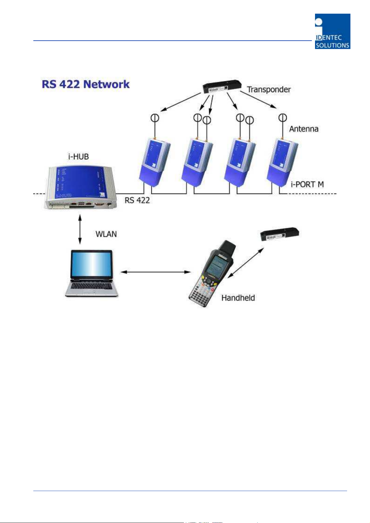
Figure 1: ILR System Components
ILR System Components:
• Tags from the i-B series transmit stored data over large distances. The high data transmission rate
ensures optimal communication.
• The fixed reader (i-PORT MB) receives the data transmitted by the tags in regular intervals and buffers
the received data for later transmission via a RS422 network connected to a master PC.
• Handheld readers, based on the PC-card i-CARD R2 or Compact Flash i-CARD CF iB, can also be used to
receive transmissions from the tags over distances up to 30m. After decoding this data can either be
processed locally or transferred to a network via optional radio cards (WLAN, GPRS).
Version 1.1 02.02.2007 Page 6/
37
i-PORT MB – Manual
2.0 COMPONENTS
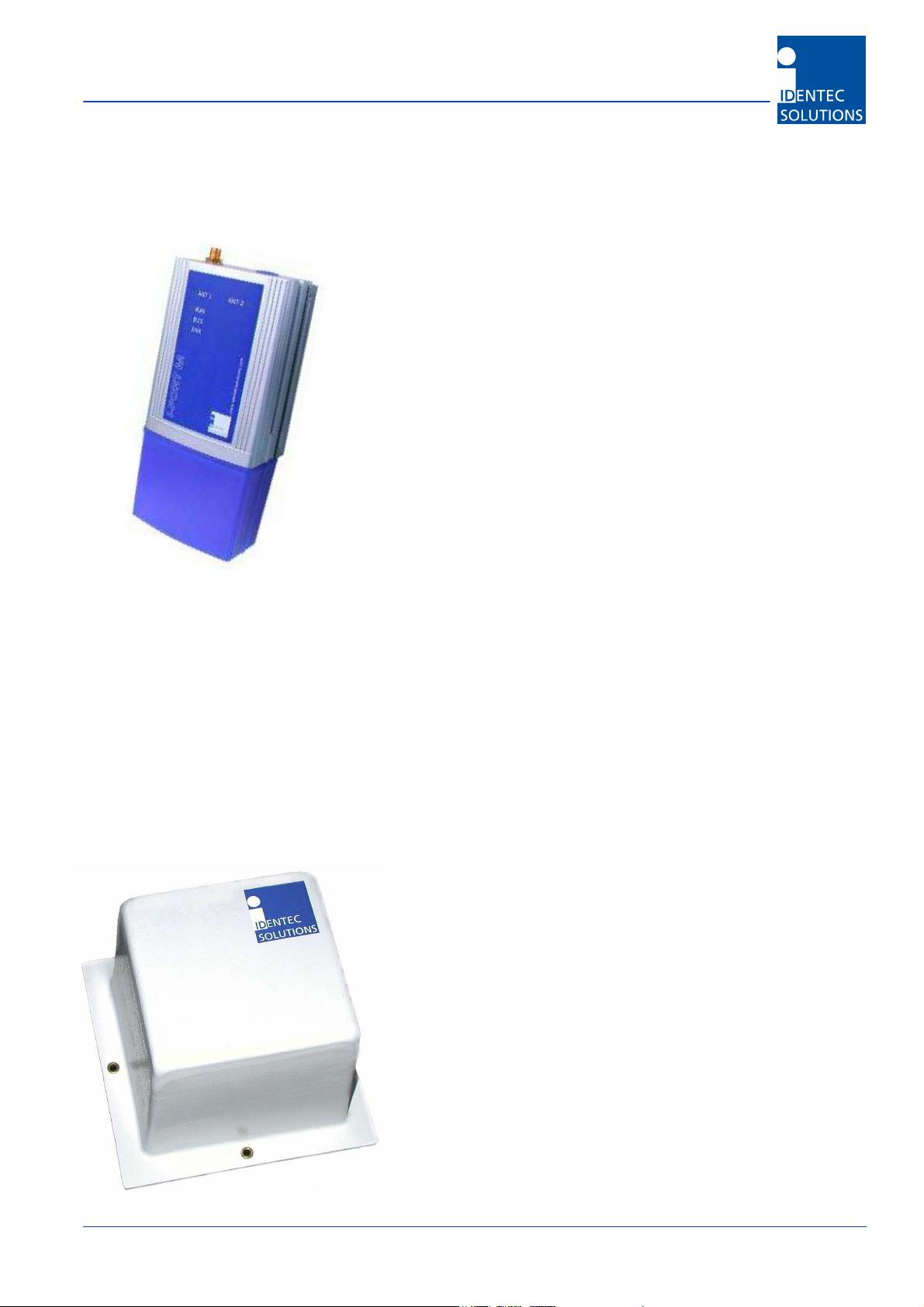
2.1 i-PORT MB
The i-PORT MB is a reader for the i-B series of ILR® Broadcast Tags.
Built into a compact plastic housing, the i-PORT MB receives
transmissions from the i-B tags at distances of up to 100 meters (300
feet). Connection to the host system is established via a RS422
interface, resulting in the capability to connect up to 8 readers in a
Daisy Chain using commercially available CAT 5 cables and
connectors.
A simple master/slave protocol enables data exchange. Not only does
the protocol contain the data received from the tag but it can also
provide information about the time of data reception, field strength
and information about the number of times the tag has been
received by the reader.
2.2
Antennas (EU only)
IDENTEC SOLUTIONS’ antennas are distinguished by their compact design. A variety of antennas can be
used, depending on application. The antennas are differentiated by characteristics such as polarization, apex
angle, and gain. Optimal fit to the read zone is achieved by the right choice of antenna (characteristics) and
receive sensitivity. As the antennas are passive system elements, no tuning is required, which facilitates
installation and maintenance.
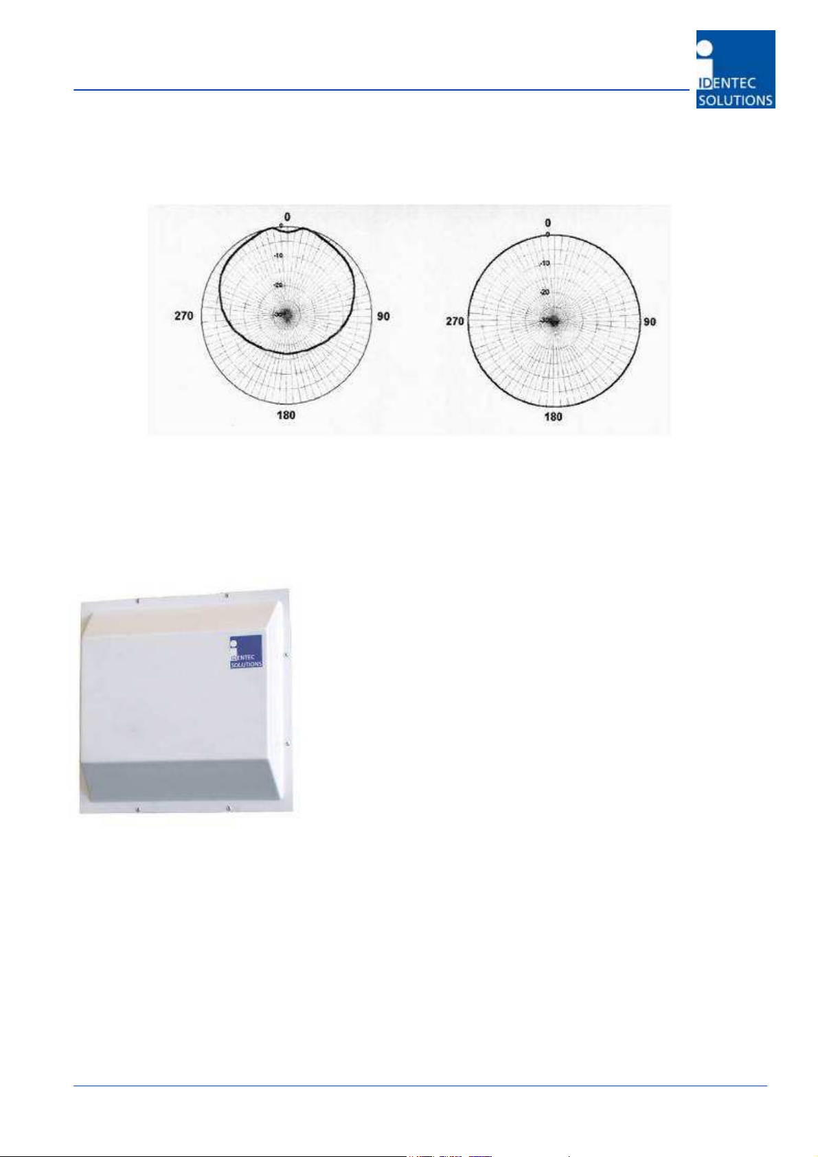
Elliptical Polarized Antennas
Because of the wide apex angle (120º) a large read zone is
achieved, which is desirable when a large quantity of tags
need to be read at one time, or when tags moving at great
speeds need to be interrogated.
Since the polarization is elliptical, orientation of the tag
relative to the antenna is not important: if the tag is in front
of the antenna the tag may be polarized horizontally or
vertically along the line of sight of the antenna. Due to its
small size and weight, this antenna is very easy to integrate.
Version 1.1 02.02.2007 Page 7/37
i-PORT MB – Manual
Orientation Diagrams: Elliptical polarized antenna
Elevation Azimuth
Linear Polarized Antennas
Because of the smaller apex angle (60º), this antenna is more
suited to selective data collection and restriction of read zones.
Depending on the direction of mounting, the antenna’s field is
either vertically or horizontally polarized, requiring the tag to
have the same orientation.
Because of the greater gain, longer read ranges can be
achieved with this antenna compared to the elliptical polarized
type above.
Version 1.1 02.02.2007 Page 8/37
Antenna Orientation
i-PORT MB – Manual
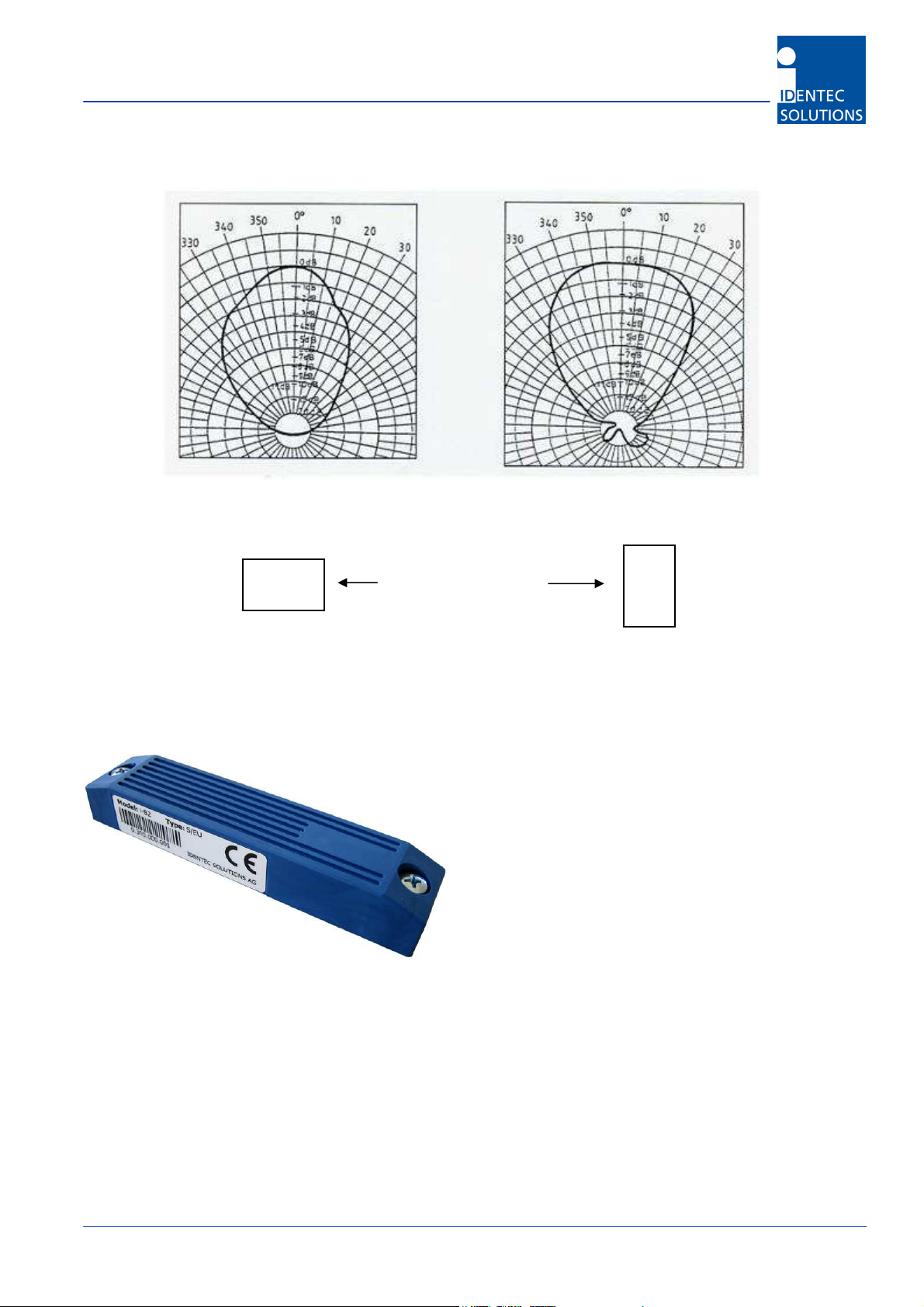
Orientation Diagrams: Linear polarized antenna
Elevation Azimuth
Vertical Polarization Horizontal Polarization
2.3. i-B Tag
This active tag is particularly suited for:
- Identification
- Tracking and Tracing
Using ILR technology, distances of up to 100 meters
(300 feet) can be achieved with this tag. An
operation lifetime of up to 6 years (depending on
ping rate) can be expected due to the tag’s minimal
energy requirement.
Used in combination with the i-PORT R2 or i-CARD R2, several hundred tags can be detected nearly
simultaneously, thanks to an anti-collision algorithm.
i-B tags are available in a variety of configurations and form factors. Memory capacity is 13 Byte (17
characters packed). Furthermore, they are available at 868 MHz for use in Europe and at 915 MHz for use in
America.
Version 1.1 02.02.2007 Page 9/37

i-PORT MB – Manual
Polarization is dependent on orientation and is rotation symmetrical.
Vertically Polarized Horizontally Polarized
3.0 INSTALLATION AND SET-UP
IDENTEC SOLUTIONS’ ILR-System consists of several components:
• Tags (also called transponders)
• Readers (fixed i-PORT reader or i-CARD in mobile handheld/notebook)
• Antennas
• A central computer system as basis for control and monitoring
or a handheld with an i-CARD
Before installation, the user should have thorough knowledge of the application. The read locations need to
be defined; whether the object is moving or stationary needs to be determined. If the objects in question are
moving objects, their speed is important for calculating receiving probability and the needed ping rate of the
tag.
Mounting Site:
The i-PORT should be mounted fairly close to the read location as lengthy antenna cables reduce the range of
the system. A 10-meter coaxial cable (RG 58 C/U) shows a loss of 6 dB. This in turn means a reduction of the
read range by 50% (see diagrams).
Version 1.1 02.02.2007 Page 10/37

i-PORT MB – Manual
Cable losses as a function of cable length are displayed in the above diagram. The values are based on an
RG58 coaxial cable at a frequency of 900 MHz.
In the diagram above, the relative range is displayed as a function of the cable length. Relative because the
range is dependent on the environment of the system. Under ideal conditions (free field, i-PORT R2), ranges
of up to 100 meters (300 feet) can be achieved. But if 20 meters of antenna cabling are used, the cable
losses amount to approx. 12 dB, which reduces the original range to just one-quarter (25 meters)!
The range losses as displayed in the diagram are independent of the original range. If the range is 30 meters
(100 feet) and 10 meters of antenna cabling are used, the range is reduced by 50%.
After mounting the i-PORT MB, the antennas need to be installed and connected to the designated antenna
sockets. If antenna extension cables are required, check these for function or short circuits before you begin
with the start-up.
Version 1.1 02.02.2007 Page 11/37
i-PORT MB – Manual
Alignment of Antennas:
Align the antennas with the tags or the objects to be monitored. Linearly polarized antennas must have the
same polarization as the tags, either horizontal or vertical. Circular polarized antennas are not dependent on
the polarization of the tags.
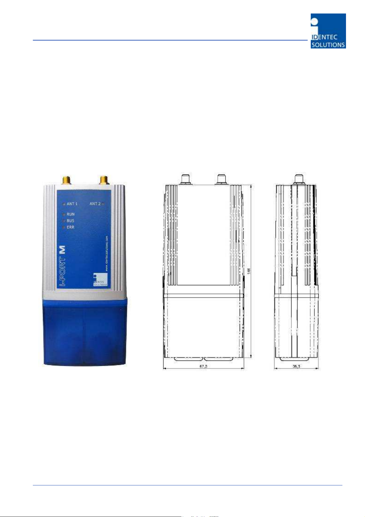
3.1 Mounting the i-PORT MB
Dimensions without mounting kit and with end cap
Version 1.1 02.02.2007 Page 12/37

i-PORT MB – Manual
Dimensions without mounting kit and without end cap
Mounting kit
Version 1.1 02.02.2007 Page 13/37

i-PORT MB – Manual
The mounting kit is to be clipped on the back of the i-PORT MB, there is 5 mm space left for the screws
between the mounting kit and the reader.
Use the two mounting holes (diameter 4,5 mm) to attach the i-PORT MB mounting kit to a suitable mounting
surface. Once the mounting kit is fixed, clipped in the i-PORT MB reader.
Please add to the i-PORT MB dimensions approximately 70 mm on the antenna side and 40 mm on the cable
side to calculate the required mounting space. The i-PORT MB weights approx. 150 g.
Enclosure rating is IP40 without the end cap and IP64 with. If greater enclosure rating is required, the i-PORT
MB must be placed in an additional protective housing, in this situation the end cap could be removed.
Version 1.1 02.02.2007 Page 14/37

i-PORT MB – Manual
3.2 Interfaces and LED Displays
T568B colors
1 - RX+ 1 - TXS+ 1 - White/orange
2 - RX- 2 - TXS- 2 - Orange
3 - TX+ 3 - RXS+ 3 – White/Green
4 - V+ (10..30V) 4 - V+ 4 – Blue
5 - V+ (10..30V) 5 – V+ 5 – White/Blue
6 - TX- 6 - RXS- 6 - Green
7 - GND 7 – GND 7 - White/Brown
8 - GND 8 - GND 8 - Brown
Please note:
- The device uses RS422 levels on its RX and TX Pins, although Ethernet jack/plugs
mechanically fit, the device is not Ethernet compatible.
- Industry standard cat 5 straight patch cables can be used to daisy chain the devices
Connectors:
To Master: RJ 45 connector to the Host computer or the Slave port of the previous i-PORT MB in the Daisy
Chain.
To Slave: RJ 45 connector to the Master port of the next i-PORT MB in the Daisy Chain. Leave this
connector open at the last device in the chain.
Connection parameters:
Signal levels: RS422
Baud rate: 115200 bits per second
Data bits: 8
Stop bits: 1
Parity: none
Mode: half duplex
Version 1.1 02.02.2007 Page 15/37

i-PORT MB – Manual
Status LEDs:
ANT 1/ANT 2
LED blinks green when a telegram preamble has been detected.
It blinks RED when a tag telegram has been decoded correctly
and the tag RSSI level is within the limit defined in the
parameters (Tag RX entry level and tag RX exit level).
RUN
Device is running properly (LED blinks at approx 1Hz)
BUS
Blinks GREEN when data is received from the host. Blinks RED
when sending data to the host
ERR
Blinks RED when an error occurs
Version 1.1 02.02.2007 Page 16/37

i-PORT MB – Manual
4.0 COMMUNICATION PROTOCOL
4.1 Telegram Structure, Escaping and CRC
Operation of the i-PORT MB follows strictly the Master/Slave principle. Readers are slaves and there is no
information sent by the readers unless requested by the master computer.
The data is divided into separate messages with the following structure:
SOH Addr Cmnd data ... Crc16 EOT
SOH and EOT are the ASCII characters 0x01 and 0x04, respectively.
Addr is the bus address of the telegram recipient.
Cmnd represent the command ID or response ID.
Data represent the Command specific information.
Crc16 is the telegram cyclic redundancy check.
Bus communication
The bus has only 1 master and various slaves uniquely identified by a bus address.
Communication can only occur between the master and 1 of the slave. There is no direct
communication possible between 2 slaves.
The bus address in a telegram identifies the recipient if sent by master or the sender if sent by
slave.
Addresses 0xF0 up to 0xFD are reserved.
0xFF is the broadcast address.
0xFE addresses any reader which has its slave port disconnected which give an opportunity to communicate
with the last reader connected on the bus. This functionality is used to discover readers on the bus.
Starting at addresses >= 0x11 is recommended to avoid the need for escape sequences for the device
address.
Addresses 0x30 (‘0’) or 0x41 (‘A’) might be convenient values to start with. Commands sent to the broadcast
address cause no response unless otherwise noted. A reader addressed with 0xfe responds with its assigned
short address (as opposed to 0xfe) in its response telegram.
Escape sequences
As the protocol is binary and does not contain length information some special characters must be “escaped”
in order to allow correct reception and decoding. This is done by adding a DLE- (0x10) character and adding
binary 0x80 to the character being escaped. These characters and the corresponding escape sequences are:
Character Code Escape sequence
SOH 0x01 0x10, 0x81
EOT 0x04 0x10, 0x84
DLE 0x10 0x10, 0x90
This encoding is done after the CRC is added; removing on the receiving side must be done
before the CRC is checked.
Version 1.1 02.02.2007 Page 17/37

i-PORT MB – Manual
Using this procedure it is ensured, that neither the EOT nor the SOH character will appear in a message sent
by the reader and the host software gets a clear indication when a telegram starts and ends.
Please note, that due to these inserted characters the maximum telegram length can be nearly doubled so the
host program has to provide a sufficiently large reception buffer.
If an addressed device detects an error when receiving a command (f.e. CRC is not valid or an invalid
command is detected) the device will not respond to avoid collision of messages sent by multiple readers.
CRC calculation
Telegram integrity is ensured by adding a cyclic redundancy check to each frame.
The CRC16 is calculated according to the code provided in the appendix of this document. The CRC16 is
calculated over the entire message, including Addr and Cmnd, but excluding the delimiting characters SOH
and EOT and extra escaped characters.
Note: CRC is calculated by the sender before any DLE replacement of special characters takes place and
checked by the receiver after any DLE replacement sequence has been decoded.
General information
The protocol uses a query response scheme, so a reader does not send data unless requested to. As there is
no handshake over individual characters the host has to be able to receive the complete response.
The host shall check that there is enough memory to receive the full reader response.
If a host message is broadcasted to multiple readers using a broadcast address, there will be no response
from any reader.
The communication between readers and host is always with the Less Significant Byte transmitted first.
Any command sent by a host to a reader and decoded with no framing error will be acknowledged unless a
broadcast address has been used. In case of framing error during a message reception, the reader will not
process and not acknowledge the message.
Version 1.1 02.02.2007 Page 18/37

i-PORT MB – Manual
4.2 Get version command
Get Version Command telegram
This command is used to get both a binary version number plus a version identification string from the
reader.
Parameter Range Length/byte
Start SOH 1
Address 1
Command 0x33 1
Crc16 2
End EOT 1
Get Version Response telegram
The reader responds with a message as follows:
Parameter Range Length/byte
Start SOH 1
Address 1
Command 0xB3 (= 0x33 + 0x80) 1
Major Version 1
Minor Version 1
Info ASCII string 20
Crc16 2
End EOT 1
Version 1.1 02.02.2007 Page 19/37

i-PORT MB – Manual
4.3 Get Tags command
Command telegram
After power-up the reader automatically starts reading and stores detected tags in an internal list. With this
command the tags can be retrieved from the reader:
Parameter Range Length/byte Remark
Start SOH 1
Address 1
Command 0x41 1
SubCmd 0x00 1
CRC16 2
End EOT 1
Response telegram
The Reader can be configured to send more than one Response telegrams to one Get Tags Command. The
maximum number can be configured by the Set Parameter command (see below).
If less than 256 tags have newly been detected, these tags will be transmitted in their detection order.
Additional tags or tags which are re-reported (see parameters 0x13, 0x15) might be transmitted in any order.
Parameter Range Length/byte Remark
Start SOH 1
Address 1
Command 0xC1 1
Status 0x00/0x10 1 Note 1
AgeCount 2 Note 2
TagID 4 LSB first
UserData 9 Note 3
Flags 1 Note 4
RSSI 1 Note 5
CRC16 2
End EOT 1
Notes:
1 Status is 0x00 on success. If all received tags have been sent but the maximum number of response
telegrams (see Set Parameter 16 below) is not reached an empty telegram is sent as termination. In
this status is set to 0x10, data to binary 0x00 and RSSI to –128.
If the number of response telegrams is limited by parameter 0x16 the inner loop could follow the
algorithm (Pseudo-C)
for( i=0; i<Parameter_0x16_Number_of_tags_allowed; i++ )
{
receive_response_telegram();
if( (0x10 == response_telegram.status) || timeout )
break;
else
Version 1.1 02.02.2007 Page 20/37

i-PORT MB – Manual
process_response_telegram();
}
2 The transmitted AgeCount contains the lower 8 bits b0..b7
and the highest 8 bits b20..b27 of the tag age counter
c0..c15 (this is the result of a “mapping” of the 32 bit age
counter on the tag to 2 byte transmitted by RF).
The lowest bits are used to change telegram contents and encryption between transmissions while
the upper bits are used to estimate tag life (and remaining lifetime). This byte counts up by one
roughly all 1 million telegrams (12 days @ 1 second ping rate).
3 9 byte of data, can be programmed according customer’s need by IDENTEC SOLUTIONS or
representative
4 1 byte of flags, are set during programming of tag. Depending on tag version additional information
(i.e. battery status in bit7) can be part of this byte. The lowermost 6 bit are freely available (Tag
Firmware 0.3).
5 Signal strength of tag as signed char (0xff = -1dBm, 0x80 = -128dBm). This is the maximum RSSI
value of the last detection recorded on both antennas. If the last detection was on 1 antenna only
then the reader returns the RSSI of this antenna.
Version 1.1 02.02.2007 Page 21/37

i-PORT MB – Manual
4.4 Get Tag extended command
Command telegram
This command corresponds to the “Get Tags” Command but requests additional information.
Parameter Range Length/byte Remark
Start SOH 1
Address 1
Command 0x42 1
SubCmd 0x00/0x01 1 With 0x01 an additional
TelegramCount is transmitted, see
below
CRC16 2
End EOT 1
Response telegram
Parameter Range Length/byte Remark
Start Delimiter SOH 1
Addr 1
Cmnd 0xc2 (= 0x42 + 0x80) 1
Status 0x00/0x10 1 See remark at “Get Tags Response
telegram”
Len 1
HFProtID 1 As transmitted by the tag
AgeCount 3 MSB currently not used
TagID 4 LSB first
UserData 9
Flags 1
BatteryNumber 1 Not used (reserved)
DecryptKeyIndex 1 Not used (reserved)
Reserved 4 Not used (reserved)
TimeFirst 4 Time first detected (Note 1)
TimeLast 4 Time last detected (Note 1)
RSSI 1 Receive Signal Strength Indicator
RSSI(max) 1 Maximum RSSI since last transmission
#seen 1 number of times tag was detected
since last transmission to host
Version 1.1 02.02.2007 Page 22/37

i-PORT MB – Manual
TelegramCount 0/1 This byte is only transmitted if the
SubCmd is 0x01. It is incremented
each time it is transmitted. If the value
on host and reader are inconsistent the
complete list of tags can be scheduled
for retransmission with parameter
0x15. If you should see errors here
please also check for timeouts and crc
errors on the host and on the reader
(parameter 0x04)
crc16 2
End Delimiter EOT 1
Note 1: Time in seconds, signed integer (relative to the time the last command was issued).
TimeFirst:This is the first time the tag has been detected on one of the antenna
TimeLast: This is the last time the tag has been detected on one of the antenna
RSSI: This is the maximum value of the last detection information on both antennas
MAX(RSSI ant 1, RSSI ant2) for last detection time.
RSSI Max this is the maximum RSSI value detected on any antenna. MAX (Max RSSI ant1, Max
RSSI ant2) since last transmission.
#seen: This is the maximum number of detection of the tag on both antenna MAX(#seen
ant1, #seen ant2) since last transmission.
Version 1.1 02.02.2007 Page 23/37

i-PORT MB – Manual
4.5 Get Tag Full command
This command corresponds to the “Get Tags extended” Command but requests additional information
regarding all antennas.
Command telegram
Parameter Range Length/byte Remark
Start SOH 1
Address 1
Command 0x40 1
SubCmd 0x00/0x01 1 With 0x01 an additional
TelegramCount is transmitted, see
below
CRC16 2
End EOT 1
Response telegram
Parameter Range Length/byte Remark
Start Delimiter SOH 1
Addr 1
Cmnd 0xc0 (= 0x40 + 0x80) 1
Status 0x00/0x10 1 See remark at “Get Tags Response
telegram”
Len 1
HFProtID 1 As transmitted by the tag
AgeCount 3 MSB currently not used
TagID 4 LSB first
UserData 9
Flags 1
BatteryNumber 1 Not used (reserved)
DecryptKeyIndex 1 Not used (reserved)
Reserved 4 Not used (reserved)
TimeFirst Ant 1 4 Time first detected (Note 1)
TimeLast Ant 1 4 Time last detected (Note 1)
RSSI Ant 1 1 Receive Signal Strength Indicator
RSSI(max) Ant 1 1 Maximum RSSI since last transmission
#seen Ant 1 1 number of times tag was detected
since last transmission to host
TimeFirst Ant 2 4 Time first detected (Note 1)
TimeLast Ant 2 4 Time last detected (Note 1)
RSSI Ant 2 1 Receive Signal Strength Indicator
RSSI(max) Ant 2 1 Maximum RSSI since last transmission
#seen Ant 2 1 number of times tag was detected
since last transmission to host
Version 1.1 02.02.2007 Page 24/37

i-PORT MB – Manual
TelegramCount 0/1 This byte is only transmitted if the
SubCmd is 0x01. It is incremented
each time it is transmitted. If the value
on host and reader are inconsistent the
complete list of tags can be scheduled
for retransmission with parameter
0x15. If you should see errors here
please also check for timeouts and crc
errors on the host and on the reader
(parameter 0x04)
crc16 2
End Delimiter EOT 1
Note 1: Time in seconds, signed integer (relative to the time the last command was issued).
Version 1.1 02.02.2007 Page 25/37

i-PORT MB – Manual
4.6 Set parameter command
Command telegram
This command is used to initialize and configure the reader. All the parameters and functions are defined in a
sub- command field contained in the telegram.
Parameter Range Length/byte Remark
Start SOH 1
Address 1
Command 0x43 1
SubCmd 1 See table below
Arg 4 See table below. Most
significant byte first.
CRC16 2
End EOT 1
Response telegram
Parameter Range Length/byte Remark
Start SOH 1
Address 1
Command 0xc3 1
Status 1 Note: 0x00 denotes success, 0x11
Voltage to low to write
CRC16 2
End EOT 1
Version 1.1 02.02.2007 Page 26/37

i-PORT MB – Manual
4.7 Get parameter command
Command telegram
Parameter Range Length/byte Remark
Start SOH 1
Address 1
Command 0x44 1
SubCmd 1 See table below
CRC16 2
End EOT 1
Response telegram
Parameter Range Length/byte Remark
Start SOH 1
Address 1
Command 0xc4 1
Status 1
Argument 4 Most significant byte first.
CRC16 2
End EOT 1
Version 1.1 02.02.2007 Page 27/37

i-PORT MB – Manual
4.8 Reader parameters list
Each parameter is coded on 4 bytes with LSB transmitted first.
ID R/W Default
0x00 W NA Reset To default Used to reset all parameters to default values.
0x01 R Serial number Reader serial number
0x02 R NA Up Time Seconds since last reset
0x03 R NA CheckSum and
0x04 R NA Status See Reader Status information table
0x05 R NA External supply
0x06 R NA Get temperature Internal voltage in units of 1/100th degree Celsius. This is an
0x10 R/W 1 Slave port
0x11 R/W 0 Bus Address 0x00 up to 0xEF
0x12 R/W 60 Inhibit Time Time in seconds until tag is removed from the internal list.
0x13 R/W 60 Re-reporting
0x14 R/W 0 List behaviour
0x15 W NA List command 0x00 - Clear list now
0x16 R/W 0 Max transmitted
0x17 R/W -128 Tag entry RX level Signed char
0x18 R/W -128 Tag exit RX level Signed char
0x19 R/W 1 RF sensitivity 0x00 – low sensitivity (-55 dBm)
0x1A R/W -70 RF reference level Signed char (used for HF statistics, default –70dBm.
Definition Description
Byte 0 Checksum Status
bootloader
voltage
connected
interval
tags
Byte 1 Boot loader version
below for bit definition
In mV.
estimate of CPU temperature, don’t use this.
0 Disconnect
1 Connect (always default value after Power-up)
0x00 – don’t remove tags from list
When using 0x00 here the host application typically should
clear or reschedule the list (SubCmd 0x15) on startup
0x00 – do not re-report.
time in seconds after which a tag is re-reported if it is still
detected. See Note 1
0x00 discard old tags if list gets too full. This is the
recommended setting for most applications.
0x01 clear list if list gets too full.
0x04 remove tags from list when they are reported. This
mode is used to determine the ping rate of the tag.
Please Clear or reschedule list (SubCmd 0x15) or power cycle
the device after changing this parameter
0x01 – mark all tags in list as not yet reported. This causes a
resend of all tags in memory (‘schedule for retransmission’).
Set to any number below 100. Allows for predictable runtime
behaviour of the host application.
0 no limit
0xff = -1dBm
0x80 = -128dBm
0xff = -1dBm
0x80 = -128dBm
0x01 – high sensitivity (-85 dBm)
0xff = -1dBm
0x80 = -128dBm
This parameter is not used in the MB reader
Version 1.1 02.02.2007 Page 28/37

i-PORT MB – Manual
0x1B R/W -128 Tag entry RX level
Ant 1
Signed char
0xff = -1dBm
0x80 = -128dBm
0x1C R/W -128 Tag exit RX level
Ant 1
Signed char
0xff = -1dBm
0x80 = -128dBm
0x1D R/W 1 RF sensitivity Ant 1 0x00 – low sensitivity (-55 dBm)
0x01 – high sensitivity (-85 dBm)
0x1E R/W Reserved
0x1F R/W 0 RF offset Ant 1 Signed char in dB
This offset is added to the tag RSSI value before being
processed
0x20 R/W -128 Tag entry RX level
Ant 2
Signed char
0xff = -1dBm
0x80 = -128dBm
0x21 R/W -128 Tag exit RX level
Ant 2
Signed char
0xff = -1dBm
0x80 = -128dBm
0x22 R/W 1 RF sensitivity Ant 2 0x00 – low sensitivity (-55 dBm)
0x01 – high sensitivity (-85 dBm)
0x23 R/W Reserved
0x24 R/W 0 RF offset Ant 2 Signed char in dB
This offset is added to the tag RSSI value before being
processed
0x25 R/W Frequency This parameter is writable only if the reader supports more
than 1 frequency and the frequency can be changed otherwise
it will return the reader frequency.
1 EU
2 NA
0x26 R/W Reserved
Note 1: Tags which have not been detected for an interval longer on than the inhibit time (and have been
transmitted to the host) are removed from the list. Tags which are still in the list are re-reported if the rereporting interval has expired.
Tags are only removed from the list after one of those conditions:
• Tag is reported and the inhibit time condition occurs.
• The list is full and list behaviour is set to 0
• After issuing a clear list command (parameter 0x15).
List Command:
When a tag is reported, the maximum RSSI value and Number of count seen are resetted so after using the
List command to mark all tag has not reported, the get Tag command may return a list of tag with invalid
Maximum RSSI value or count number.
Parameters 0x17 to 0x1A are used for compatibility with the iPort R2 reader.
These parameters should be used only if we do not need to know on which antenna a tag has been detected
and if the parameters are identical on both antennas.
CAUTION:
If these parameters are used please DO NOT USE parameters 0x1B to 0x24 and vice-versa.
The reader uses parameters above 0x1A, setting parameters 0x17 to 0x1A will also change
corresponding parameters above 0x1A. If one of the parameters above 0x1A is changed, reading
parameters 0x17 to 0x1A may return an invalid value.
Version 1.1 02.02.2007 Page 29/37

i-PORT MB – Manual
Inhibit Time:
This parameter defines the maximum time the tag must not be detected by the reader before to be removed
from the internal list.
A tag is removed only if it is marked as reported. If the tag was not marked as reported, it will stay in the list
as long as it is not reported or removed from the list.
If List behavior is equal to 4 then the tag is removed from the list as soon as it is reported so this parameter
has no effect.
Re-Report interval:
If a tag has been reported to a host with the GetTag commands, it will be reported only after the Re-report
time interval and only if it has been detected again.
If List behavior is equal to 4 then the tag is removed from the list as soon as it is reported so this parameter
has no effect.
RF Offset:
This offset is added to the tag RSSI value just after detection and before being processed by the reader.
This setting may be useful when the RF path loss from the reader to the antenna (included) is not identical on
both antenna due to longer cable length or antenna with different gain.
Version 1.1 02.02.2007 Page 30/37

i-PORT MB – Manual
4.9 Reader status information
The GetParameter Command (with parameter ID = 4) is identified as the GetStatus command.
The get status command returns 32 bits, this table details the type of error each single bit indicates.
If a bit is set, it indicates the defined error occurred at least once since the last Getstatus command was sent.
All status bits are cleared after reception of the Getstatus command.
More than 1 bit can be set at the same time.
Status bit
position
0 CRC CRC of telegram received is not valid
1 Host command Unknown command
2 Internal version This firmware is not a released version
3 Host timeout Timeout receiving command from host
4 Escape DLE not used
5 Reserved
6 Reserved
7 Rebooted The device has rebooted
8 EEPROM parameter CRC Checksum over EEPROM parameters is invalid and reset to
9 Watchdog reboot Hardware or software failure
10 EEPROM calibration CRC Checksum over EEPROM calibration/configuration is invalid
11 Reserved
12 Reserved
13 Reserved
14 Reserved
15 Fallback Software The device has 2 firmware images and the checksum over
16 Supply voltage too low was
17 Current supply voltage too
18 Temperature out of range
19 Temperature out of range
30 Clock error Quartz error.
31 I2C error EEPROM error.
Definition Description
Invalid escape sequence detected
properly
default values.
and reset to default values. Please contact IDENTEC
Solutions AG
the last image fails so the device run the previous
firmware
The voltage has been detected too low at least once since
detected once.
low.
(too cold)
(too hot)
the last status query.
Current voltage is too low.
The temperature has been detected too cold (< -20°C) at
least once since the last status query.
The temperature has been detected too hot (> +80°C) at
least once since the last status query.
Version 1.1 02.02.2007 Page 31/37

i-PORT MB – Manual
5.0 INSTALLATION- CONFIGURATION
This chapter provides some useful hints and procedures how the reader should be used under different
operating modes
5.0 Device enumeration
On power-up the “To Slave” RJ45 port of the reader transparently transmits and receives data from and to
the “To Master” RJ45 port. The device responds to either the broadcast address or the last static address
assigned to the device.
Proposed enumeration algorithm on first time enumeration:
a) Send connect slave port (parameter 0x10) to the broadcast address (n times for n readers)
b) Send disconnect slave port to the broadcast address. Only the first reader with a disconnected slave
port in the chain will respond to a command send to address 0xfe now.
c) Read serial number, set unique static address for the reader with the disconnected slave port
(address 0xfe).
d) Read status (parameter 0x04) and check supply voltage (parameter 0x05).
e) Connect slave port and return to step c) (n times for n readers)
At normal application start-up a new device enumeration is not necessary but the above scheme can be used
to check for readers which might have been newly connected and which possibly have a static address which
has already been assigned to another reader. It is recommended to check whether the combination of serial
number and static address match for all readers.
5.1 First time installation (“site setup”)
− Enumerate readers
− check that voltages are OK
− store corresponding serial numbers (parameter 0x01) and short address (parameter 0x11) on host
− Setup parameters for list behaviour and RF, additionally save these in host system.
Remarks:
− After initial setup the program on the host is not expected to do frequent changes of parameters
marked as “permanent” in the table for the set parameter command.
− Apart from first time installation the application on the host application should not need to know about
parameters like i.e. the RF sensitivity.
Version 1.1 02.02.2007 Page 32/37

i-PORT MB – Manual
5.2 Normal initialization (“application on host starting up”)
− Enumerate readers
− check that voltages are OK
− For each reader get serial number and compare to values stored on host.
− Report mismatch as error, if desired automatically redo first time initialization.
5.3 Normal operation (“host application loop after startup”)
− The host application typically polls the readers for data (with the commands “Get Tags” or “Get Tags
Extended”).
− Besides processing these data the host application might routinely log or monitor the uptime of the
readers (parameter 0x02) and the status (parameter 0x04) for error conditions (voltage, crc, timeout).
5.4 Error recovery
Tag data of broadcast tags is inherently acquired without handshake and thus might potentially be missed by
RF detection.
The communication errors on the RS422 lines usually fall into the categories Timeout/Framing Error/CRC
Error/lost character/unexpected characters received. Most probable causes for these are:
− supply voltage at the readers is too low
− dropped characters on host receive side
− cabling problems
− reader malfunction
− Changing reader configuration without knowing of the host application.
As the communication over the serial RS422 link is considered stable and the tag data has been acquired
without handshake the protocol only foresees a retransmit for a single response telegram (firmware revision
≥0.4).
If the data telegrams of the reader are considered very valuable the host program is expected to use the “get
tags extended” telegram which includes the time of first and last detection and a message counter.
On errors the complete data on the reader can be rescheduled for transmission and reprocessed. As error
recovery code is always critical and seldom tested well, this ensures the recovery can be done using the same
algorithm which would be needed for readers which have an intermittent connection to the host.
Connect up to 16 Readers per RS422 line. While the protocol supports more and the signal levels are
refreshed by the daisy-chained readers this limit is imposed the skew between hi/lo and lo/hi transitions on
the data lines. Please note the buffering schemes of the readers allow to significantly reduce the amount of
the transmitted data but the accumulated data rate of events (like newly detected tags or tag re-reporting)
should be lower than the net data rate on the RS422 line.
5.5 How to use inhibits time, re-report interval and list behavior.
When the list behaviour is set to 4 remove tag when reported, the parameters inhibit time and re-report
interval have no influence on the system.
See in the table below for some typical settings:
Version 1.1 02.02.2007 Page 33/37

i-PORT MB – Manual
Inhibit
Application
Gate
application
Area inventory 300 10 0 optional Tag is reported if it enters the reading
Area inventory
with low
bandwidth to
database
Tag control or
test purpose
time
(seconds)
60 0 0 no Tag is reported once if it enters the
300 290 0 yes Keeping a database with a time resolution
NA NA 4 no Allows getting each transmission of the
Rereporting
time
(seconds)
List
behaviour
Uses get
tags
extended
telegram
Remark
reading range and reported again if it
reenters after not having been detected
for longer than the inhibit time value (60
seconds).
range. If it stays within the reading range
it is reported again if 10 seconds have
expired since the last reporting. A short
re-reporting time is typical for
applications which use the short “Get
Tags” command.
of f.e. 300 seconds needs at least one
message in the interval. So the rereporting time is set slightly shorter than
300 seconds (sum of tag ping rate,
message transfer latency, jitter of
message transfer latency and of database
query cycle jitter have to be accounted
for).
Use fields TimeFirst and TimeLast in the
Get Tags extended Command telegram.
tag to f.e. check for the ping rate.
Typically this will be used in conjunction
with a low sensitivity setting. Note: this
mode causes the highest traffic on the
bus. The parameters inhibit time and rereporting time don’t have an effect in this
mode and are left at the default setting
here.
5.6 Exchanging a reader within the daisy chain
− Stop the application program on the host
− exchange the reader
− Restart the application program on the host. If the application on the host checks on startup the
readers serial numbers as recommended, it will detect the changed configuration and require either
manual intervention or automatically configure the reader.
Version 1.1 02.02.2007 Page 34/37

i-PORT MB – Manual
TECHNICAL SPECIFICATIONS
Technical Specifications
Read Range: Up to 100m; adjustable
Operating Frequency: 868.3 MHz (EU), 915 Mhz (NA)
Number of Antennas: 2
Antenna Connection: SMA
Transmission Security: 16 Bit CRC
Certification: CE, EN 300220 (EU), FCC part15 (US)
Program Updates: Via Host Computer Interface
Configuration Memory: EEPROM
Read Buffer: Up to 400 Tags
Host Interface: RS 422; Daisy Chain
Baud Rate: 115 kBaud, fixed
Status Display: 5 LEDs
Power Source: 10 to 30V DC
Input Power: < 0.5W
Operating Temperature: –40°C to +80°C
Humidity: up to 90% non-condensing
Maximum number of readers per daisy chain: 16
Maximum distance between any two readers: 300m
Maximum overall length of daisy chain
(With GND free power supplies at the readers): 1000m
Case Material: Plastic
Dimensions: 97 mm x 67 mm x 37 mm (157 mm x 67mm x 37
mm with end cap)
Mass: 150 g
Package Rating: IP40, IP64 with plastic end cap.
Mounting: Mounting kit with 2 mounting Holes M4
Maximum overall length of daisy chain / Cat5 cabling AWG24
Number of
readers
1 300 One 24V supply at host
2 600 One 24V supply at host
3 400 One 24V supply at host
4 250 One 24V supply at host
5 200 One 24V supply at host
10 100 One 24V supply at host
16 60 One 24V supply at host
16 1000 GND potential free power supplies at the readers
Length/m Remark
Version 1.1 02.02.2007 Page 35/37

i-PORT MB – Manual
6.0 APPENDIX
7.1 Sample CRC calculation
The following sample code is provided ‘as is’. IDENTEC SOLUTIONS does not guarantee compatibility with any
interface or protocol except this used in the standard version of the i-PORT R2.
//! crc table for host communication
unsigned char code crc_tab_hi[256] = // table of CRC values for high order byte
{
0x00, 0xc1, 0x81, 0x40, 0x01, 0xc0, 0x80, 0x41, //01
0x01, 0xc0, 0x80, 0x41, 0x00, 0xc1, 0x81, 0x40, //02
0x01, 0xc0, 0x80, 0x41, 0x00, 0xc1, 0x81, 0x40, //03
0x00, 0xc1, 0x81, 0x40, 0x01, 0xc0, 0x80, 0x41, //04
0x01, 0xc0, 0x80, 0x41, 0x00, 0xc1, 0x81, 0x40, //05
0x00, 0xc1, 0x81, 0x40, 0x01, 0xc0, 0x80, 0x41, //06
0x00, 0xc1, 0x81, 0x40, 0x01, 0xc0, 0x80, 0x41, //07
0x01, 0xc0, 0x80, 0x41, 0x00, 0xc1, 0x81, 0x40, //08
0x01, 0xc0, 0x80, 0x41, 0x00, 0xc1, 0x81, 0x40, //09
0x00, 0xc1, 0x81, 0x40, 0x01, 0xc0, 0x80, 0x41, //10
0x00, 0xc1, 0x81, 0x40, 0x01, 0xc0, 0x80, 0x41, //11
0x01, 0xc0, 0x80, 0x41, 0x00, 0xc1, 0x81, 0x40, //12
0x00, 0xc1, 0x81, 0x40, 0x01, 0xc0, 0x80, 0x41, //13
0x01, 0xc0, 0x80, 0x41, 0x00, 0xc1, 0x81, 0x40, //14
0x01, 0xc0, 0x80, 0x41, 0x00, 0xc1, 0x81, 0x40, //15
0x00, 0xc1, 0x81, 0x40, 0x01, 0xc0, 0x80, 0x41, //16
0x01, 0xc0, 0x80, 0x41, 0x00, 0xc1, 0x81, 0x40, //17
0x00, 0xc1, 0x81, 0x40, 0x01, 0xc0, 0x80, 0x41, //18
0x00, 0xc1, 0x81, 0x40, 0x01, 0xc0, 0x80, 0x41, //19
0x01, 0xc0, 0x80, 0x41, 0x00, 0xc1, 0x81, 0x40, //20
0x00, 0xc1, 0x81, 0x40, 0x01, 0xc0, 0x80, 0x41, //21
0x01, 0xc0, 0x80, 0x41, 0x00, 0xc1, 0x81, 0x40, //22
0x01, 0xc0, 0x80, 0x41, 0x00, 0xc1, 0x81, 0x40, //23
0x00, 0xc1, 0x81, 0x40, 0x01, 0xc0, 0x80, 0x41, //24
0x00, 0xc1, 0x81, 0x40, 0x01, 0xc0, 0x80, 0x41, //25
0x01, 0xc0, 0x80, 0x41, 0x00, 0xc1, 0x81, 0x40, //26
0x01, 0xc0, 0x80, 0x41, 0x00, 0xc1, 0x81, 0x40, //27
0x00, 0xc1, 0x81, 0x40, 0x01, 0xc0, 0x80, 0x41, //28
0x01, 0xc0, 0x80, 0x41, 0x00, 0xc1, 0x81, 0x40, //29
0x00, 0xc1, 0x81, 0x40, 0x01, 0xc0, 0x80, 0x41, //30
0x00, 0xc1, 0x81, 0x40, 0x01, 0xc0, 0x80, 0x41, //31
0x01, 0xc0, 0x80, 0x41, 0x00, 0xc1, 0x81, 0x40 //32
};
//! crc table for host communication
unsigned char code crc_tab_lo[256] = // table of CRC values for low order byte
{
0x00, 0xc0, 0xc1, 0x01, 0xc3, 0x03, 0x02, 0xc2, //01
0xc6, 0x06, 0x07, 0xc7, 0x05, 0xc5, 0xc4, 0x04 //02
0xcc, 0x0c, 0x0d, 0xcd, 0x0f, 0xcf, 0xce, 0x0e //03
0x0a, 0xca, 0xcb, 0x0b, 0xc9, 0x09, 0x08, 0xc8 //04
0xd8, 0x18, 0x19, 0xd9, 0x1b, 0xdb, 0xda, 0x1a //05
0x1e, 0xde, 0xdf, 0x1f, 0xdd, 0x1d, 0x1c, 0xdc //06
0x14, 0xd4, 0xd5, 0x15, 0xd7, 0x17, 0x16, 0xd6 //07
0xd2, 0x12, 0x13, 0xd3, 0x11, 0xd1, 0xd0, 0x10 //08
0xf0, 0x30, 0x31, 0xf1, 0x33, 0xf3, 0xf2, 0x32 //09
0x36, 0xf6, 0xf7, 0x37, 0xf5, 0x35, 0x34, 0xf4 //10
0x3c, 0xfc, 0xfd, 0x3d, 0xff, 0x3f, 0x3e, 0xfe //11
0xfa, 0x3a, 0x3b, 0xfb, 0x39, 0xf9, 0xf8, 0x38 //12
0x28, 0xe8, 0xe9, 0x29, 0xeb, 0x2b, 0x2a, 0xea //13
0xee, 0x2e, 0x2f, 0xef, 0x2d, 0xed, 0xec, 0x2c //14
0xe4, 0x24, 0x25, 0xe5, 0x27, 0xe7, 0xe6, 0x26 //15
0x22, 0xe2, 0xe3, 0x23, 0xe1, 0x21, 0x20, 0xe0 //16
0xa0, 0x60, 0x61, 0xa1, 0x63, 0xa3, 0xa2, 0x62 //17
0x66, 0xa6, 0xa7, 0x67, 0xa5, 0x65, 0x64, 0xa4 //18
0x6c, 0xac, 0xad, 0x6d, 0xaf, 0x6f, 0x6e, 0xae //19
0xaa, 0x6a, 0x6b, 0xab, 0x69, 0xa9, 0xa8, 0x68 //20
0x78, 0xb8, 0xb9, 0x79, 0xbb, 0x7b, 0x7a, 0xba //21
0xbe, 0x7e, 0x7f, 0xbf, 0x7d, 0xbd, 0xbc, 0x7c //22
0xb4, 0x74, 0x75, 0xb5, 0x77, 0xb7, 0xb6, 0x76 //23
0x72, 0xb2, 0xb3, 0x73, 0xb1, 0x71, 0x70, 0xb0 //24
0x50, 0x90, 0x91, 0x51, 0x93, 0x53, 0x52, 0x92 //25
0x96, 0x56, 0x57, 0x97, 0x55, 0x95, 0x94, 0x54 //26
0x9c, 0x5c, 0x5d, 0x9d, 0x5f, 0x9f, 0x9e, 0x5e //27
0x5a, 0x9a, 0x9b, 0x5b, 0x99, 0x59, 0x58, 0x98, //28
Version 1.1 02.02.2007 Page 36/37

www.identecsolutions.com
Europe:
i-PORT MB – Manual
0x88, 0x48, 0x49, 0x89, 0x4b, 0x8b, 0x8a, 0x4a, //29
0x4e, 0x8e, 0x8f, 0x4f, 0x8d, 0x4d, 0x4c, 0x8c, //30
0x44, 0x84, 0x85, 0x45, 0x87, 0x47, 0x46, 0x86, //31
0x82, 0x42, 0x43, 0x83, 0x41, 0x81, 0x80, 0x40, //32
};
//! CRC calculation for Host communication
unsigned int build_crc16(unsigned char *host_msg, unsigned int len)
{
unsigned char crc_hi = 0xFF; // high CRC byte initialized
unsigned char crc_lo = 0xFF; // low CRC byte initialized
unsigned char index; // will index into CRC lookup table
while (len--) // pass through message buffer
{ // and calculate the CRC
index = crc_hi ^ *host_msg++;
crc_hi = crc_lo ^ crc_tab_hi[index];
crc_lo = crc_tab_lo[index];
}
return crc_lo<<8 | crc_hi;
}
Example commands with CRC
This example shows two commands sent to a reader.
Sending “disconnect slave port” to the broadcast address:
\x01\xFF\x43\x10\x90\x00\x00\x00\x00\x3f\xDB\x04
Note, there is no response to this command as it is sent to the broadcast address. The character 0x10 has
been translated into the sequence 0x10 0x90.
Sending “get parameter serial number” to the last reader in chain:
\x01\xFE\x44\x10\x81\xF0\xE2\x04
The character 0x01 has been translated into the sequence 0x10 0x81. The device responds with its serial
number:
\x01\x11\xC4\x00\x18\x7F\x5D\xCA\x3A\x85\x04
Austria:
IDENTEC SOLUTIONS AG, Millennium Park 2, 6890 Lustenau / AUSTRIA Tel: +43 (0)5577 87387-0 Fax: +43 (0)5577 87387-15
North America:
USA: IDENTEC SOLUTIONS INC., Liberty Plaza II, 5057 Keller Springs Road Suite 375, Addison, Texas 75001 / USA Tel: +1(972) 535 4144 Fax: +1(469) 424 0404
Version 1.1 02.02.2007 Page 37/37
 Loading...