

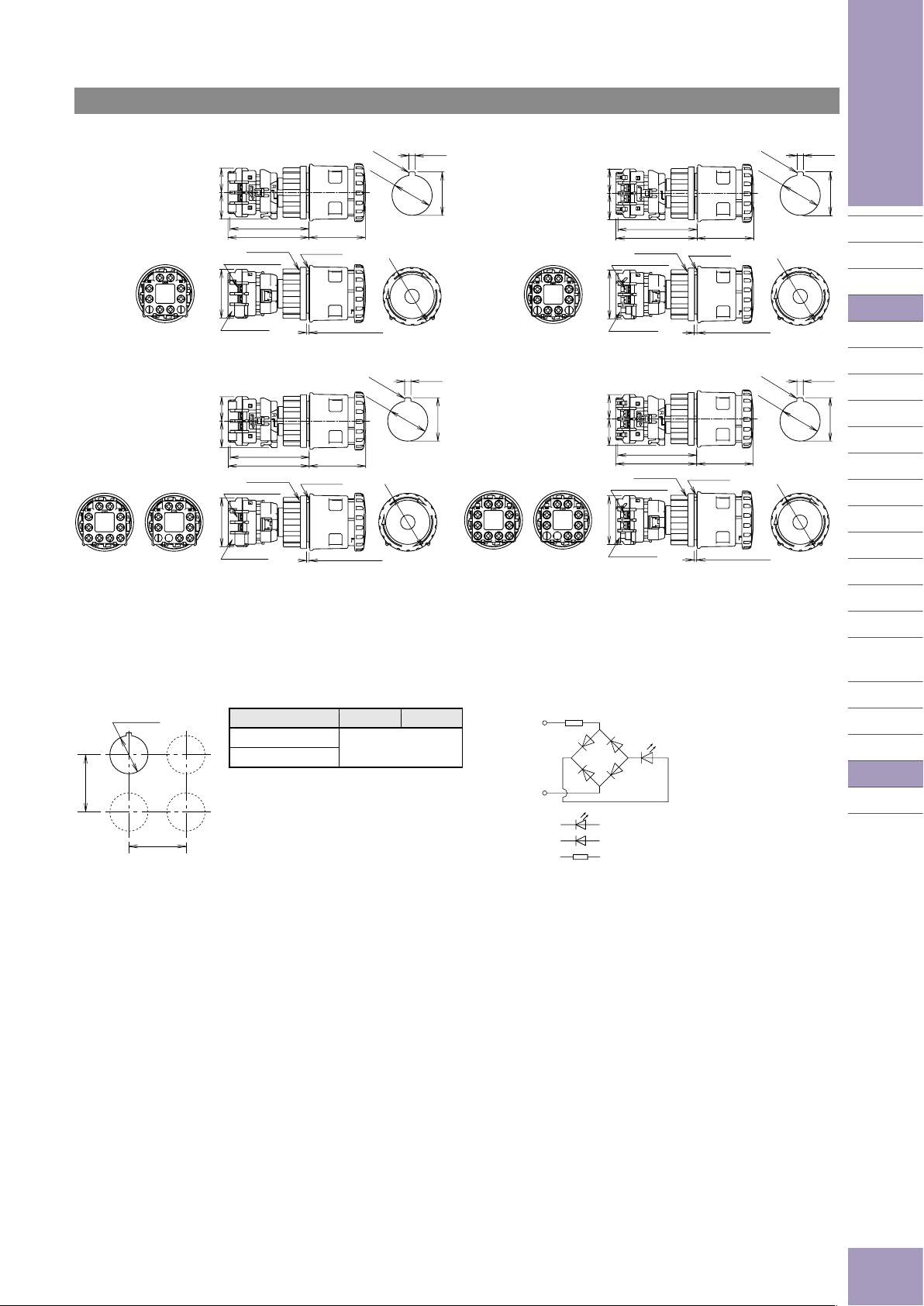
Dimensions
ø30 XN Series Emergency Stop Switches
Emergency Stop Switches
Padlockable
Non-Illuminated
R0.8 max.
ø30.5
IP20 Fingersafe
20.1 18.5
59.9
61.4
Locking Ring
M3 Terminal Screws
37
IP20 Cover
XW9Z-VL2MF
Illuminated/Push-ON
IP20 Fingersafe w/Terminal Cover
20.1 18.5
59.9
61.4
Push-ONIlluminated
Locking Ring
M3 Terminal Screws
37
IP20 Cover
XW9Z-VL2MF
Rubber Gasket
Panel Thickness 1 to 6
Rubber Gasket
Panel Thickness 1 to 6
43
R0.8 max.
ø30.5
+0.5
0
43
Panel Cut-out
ø44
+0.5
0
Panel Cut-out
ø44
+0.2
4.8
0
(*1)
w/Terminal Cover
0
+0.5
33.0
+0.2
4.8
0
(*1)
0
+0.5
33.0
Push-ONIlluminated
*1) Make sure that the panel cut-out is as shown in the drawing as the operator has a projection for anti-rotation.
20.1 18.5
Locking Ring
M3 Terminal Screws
Terminal Cover
XW9Z-VL2M
20.1 18.5
Locking Ring
M3 Terminal Screws
37
Terminal Cover
XW9Z-VL2M
+0.5
0
Panel Cut-out
ø44
+0.2
4.8
0
(*1)
0
+0.5
33.0
APEM
Switches &
Pilot Lights
R0.8 max.
ø30.5
61.4
43
Rubber Gasket
Control Boxes
Emergency
+0.2
4.8
(*1)
+0.5
0
0
33.0
Stop Switches
Enabling
Switches
Safety Products
Explosion Proof
Terminal Blocks
Relays & Sockets
Circuit
Protectors
Panel Thickness 1 to 6
R0.8 max.
ø30.5
+0.5
0
59.9
61.4
43
Rubber Gasket
Panel Cut-out
ø44
Power Supplies
LED Illumination
Panel Thickness 1 to 6
Controllers
Operator
Interfaces
Sensors
AUTO-ID
Mounting Hole Layout LED Unit Internal Circuit
+0.5
ø30.5
0
Plastic Bezel
Flush Bezel
Y
•The values shown above are the minimum
X Y
70 mm minimum
dimen sions for mounting with other ø30 mm
pushbuttons. For other control units of different
X
sizes and styles, determine the values according to the dimensions, operation, and wiring
convenience.
•For padlockable, determine the values accord ing
to the size and number of padlocks and hasp.
R
X1
LED
X2
LED chip
Protection Diode
Resistor
X6
XA
XW
XN
SEMI
D-044
 Loading...