

Page 1

KEPServerEX5 Help
© 2009 Kepware Technologies
Page 2

KEPServerEX5 Help1
Table of Contents
................................................................................................................................... 61 Getting Started
.......................................................................................................................................................... 6KEPServerEX
.......................................................................................................................................................... 6Introduction
.......................................................................................................................................................... 6System Requirements
.......................................................................................................................................................... 7Server Summary Information
................................................................................................................................... 82 Standard Features
.......................................................................................................................................................... 8Connectivity
.......................................................................................................................................................... 9Components
.......................................................................................................................................................... 9Process Modes
................................................................................................................................... 103 Server Administration
.......................................................................................................................................................... 10User Manager
.......................................................................................................................................................... 11User Properties
.......................................................................................................................................................... 11Runtime Settings
......................................................................................................................................................... 11Runtime Settings - Administration
......................................................................................................................................................... 12Runtime Settings - Configuration
......................................................................................................................................................... 13Runtime Settings - Runtime Process
......................................................................................................................................................... 14Runtime Settings - Runtime Options
......................................................................................................................................................... 15Runtime Settings - Event Log
......................................................................................................................................................... 16Runtime Settings - Host Resolution
................................................................................................................................... 174 Tag Management
.......................................................................................................................................................... 17Tag Management
.......................................................................................................................................................... 18Automatic OPC Tag Database Generation
.......................................................................................................................................................... 21System Tags
.......................................................................................................................................................... 28Property Tags
.......................................................................................................................................................... 29Statistics Tags
.......................................................................................................................................................... 31Modem Tags
................................................................................................................................... 345 Communications Management
.......................................................................................................................................................... 34Communications Management
.......................................................................................................................................................... 35Modem Support
......................................................................................................................................................... 35Using a Modem in the Server Project
......................................................................................................................................................... 37Phonebook Tag
......................................................................................................................................................... 38Phone Number
................................................................................................................................... 396 Built-In Diagnostics
.......................................................................................................................................................... 39Built-In Diagnostics
.......................................................................................................................................................... 39OPC Diagnostics
......................................................................................................................................................... 39OPC Diagnostics Window
......................................................................................................................................................... 42OPC Diagnostic Events
.......................................................................................................................................................... 47Channel Diagnostics
......................................................................................................................................................... 47Channel Diagnostics
................................................................................................................................... 507 Basic Server Components
.......................................................................................................................................................... 50Basic Server Components
.......................................................................................................................................................... 50What is a Channel?
......................................................................................................................................................... 50What is a Channel?
......................................................................................................................................................... 51Channel Properties - General
......................................................................................................................................................... 52Channel Properties - Communication Parameters
......................................................................................................................................................... 53Channel Properties - Network Interface
Page 3

......................................................................................................................................................... 54Channel Properties - Manual RTS Flow Control
......................................................................................................................................................... 55Channel Properties - Modem
......................................................................................................................................................... 56Channel Properties - Write Optimizations
......................................................................................................................................................... 58Channel Properties - Ethernet Encapsulation
.......................................................................................................................................................... 59What is a Device?
......................................................................................................................................................... 59What is a Device?
......................................................................................................................................................... 60Device Properties - General
......................................................................................................................................................... 62Device Properties - Ethernet Encapsulation
......................................................................................................................................................... 63Device Properties - Timing
......................................................................................................................................................... 65Device Properties - Auto-Demotion
.......................................................................................................................................................... 66What is a Tag?
......................................................................................................................................................... 66What is a Tag?
......................................................................................................................................................... 66Tag Properties
......................................................................................................................................................... 67Dynamic Tags
......................................................................................................................................................... 68Static Tags (User-Defined)
......................................................................................................................................................... 69Tag Scaling
......................................................................................................................................................... 70Tag Selection
.......................................................................................................................................................... 70What is a Tag Group?
......................................................................................................................................................... 70What is a Tag Group?
......................................................................................................................................................... 70Tag Group Properties
.......................................................................................................................................................... 72What is the Alias Map?
......................................................................................................................................................... 72What is the Alias Map?
......................................................................................................................................................... 73Alias Properties
................................................................................................................................... 748 Designing a Project
.......................................................................................................................................................... 74Designing a Project
.......................................................................................................................................................... 74Running the Server
.......................................................................................................................................................... 75Starting a New Project
.......................................................................................................................................................... 75Adding and Configuring a Channel
.......................................................................................................................................................... 77Adding and Configuring a Device
.......................................................................................................................................................... 79Adding User Defined Tags
.......................................................................................................................................................... 82Adding Tag Scaling
.......................................................................................................................................................... 83Saving the Project
.......................................................................................................................................................... 84Testing the Project
.......................................................................................................................................................... 90Channel Wizard
......................................................................................................................................................... 90New Channel - Name
......................................................................................................................................................... 90New Channel - Driver Page
......................................................................................................................................................... 91New Channel - Communications
......................................................................................................................................................... 92New Channel - Summary
.......................................................................................................................................................... 93Device Wizard
......................................................................................................................................................... 93New Device - Name
......................................................................................................................................................... 94New Device - Model
......................................................................................................................................................... 95New Device - ID
......................................................................................................................................................... 97New Device - Timing
......................................................................................................................................................... 97New Device - Summary
................................................................................................................................... 989 Server Options
.......................................................................................................................................................... 98Server Options
.......................................................................................................................................................... 100Runtime Connection
.......................................................................................................................................................... 101Event Log Display
.......................................................................................................................................................... 101Event Log Page Setup
................................................................................................................................... 10210 Configuring from FIX Applications
.......................................................................................................................................................... 102Project Startup for iFIX Applications
................................................................................................................................... 10311 Project Preferences
.......................................................................................................................................................... 103Project Properties
2Contents
2
Page 4

KEPServerEX5 Help3
.......................................................................................................................................................... 103OPC Settings Options
.......................................................................................................................................................... 104OPC Compliance Options
.......................................................................................................................................................... 106DDE Options
.......................................................................................................................................................... 107FastDDE & Suitelink Options
.......................................................................................................................................................... 108iFIX PDB Options
.......................................................................................................................................................... 110iFIX Signal Conditioning Options
................................................................................................................................... 11612 How Do I...
.......................................................................................................................................................... 116How Do I...
.......................................................................................................................................................... 116Use DDE with the Server
.......................................................................................................................................................... 117Use NetDDE Across a Network
.......................................................................................................................................................... 117Use Dynamic Tag Addressing
.......................................................................................................................................................... 117Process Array Data
.......................................................................................................................................................... 118Create and Use an Alias
.......................................................................................................................................................... 120Use an Alias to Optimize a Project
.......................................................................................................................................................... 121Optimize the Server Project
.......................................................................................................................................................... 122Select the Correct Network Cable
.......................................................................................................................................................... 123Use Ethernet Encapsulation
.......................................................................................................................................................... 125Resolve Comm Issues When the DNS/DHCP Device Connected to the Server is Power Cycled
................................................................................................................................... 12513 Error Messages
.......................................................................................................................................................... 125Error Descriptions
.......................................................................................................................................................... 127Server Runtime Error Messages
......................................................................................................................................................... 127Server Runtime Error Messages
......................................................................................................................................................... 128'<driver name>' device driver was not found or could not be loaded
......................................................................................................................................................... 129'<server name>' Server Started
......................................................................................................................................................... 129'<server runtime>' successfully configured to run as a system service
......................................................................................................................................................... 129'<server runtime>' successfully removed from the service control manager database
......................................................................................................................................................... 129Attempt to add DDE item '<item name>' failed
......................................................................................................................................................... 130Attempt to add FastDDE/SuiteLink item '<tag name>' failed
......................................................................................................................................................... 130Attempt to add OPC Client item '<item name>' failed
......................................................................................................................................................... 130Attempting to automatically generate tags for device '<device name>'
......................................................................................................................................................... 130Auto generation for tag '<tag name>' already exists and will not be overwritten
......................................................................................................................................................... 131Auto generation produced too many overwrites, stopped posting error messages
......................................................................................................................................................... 131Completed automatic tag generation for device '<device name>'
......................................................................................................................................................... 131Configuration session assigned to '<user name>' as Default User has ended
......................................................................................................................................................... 131Configuration session assigned to '<user name>' demoted to Read Only
......................................................................................................................................................... 132Configuration session assigned to '<user name>' promoted to Write Access
......................................................................................................................................................... 132Configuration session started by '<user name>'
......................................................................................................................................................... 132Configuration TCP/IP port number changed to '<port number>'
......................................................................................................................................................... 132Data collection is '<enabled/disabled>' on device '<device name>'
......................................................................................................................................................... 133DDE client attempt to add topic '<topic>' failed
......................................................................................................................................................... 133Delete object '<item name>' failed
......................................................................................................................................................... 133Demo timer started. '<days>' '<hours>' '<minutes>' '<seconds>'
......................................................................................................................................................... 134Demo timer updated. '<time remaining>'
......................................................................................................................................................... 134Demonstration time period has expired
......................................................................................................................................................... 134Demonstration time period has expired
......................................................................................................................................................... 135Device '<device name>' has been auto-demoted
......................................................................................................................................................... 135Device '<device name>' has been auto-promoted to determine if communications can be re-established
......................................................................................................................................................... 135Failed to upload project XML
......................................................................................................................................................... 135FLEXnet Licensing Service must be enabled to process your license
Module '<module>' is unsigned or has a corrupt signature. Runtime references are limited to demo
operation
......................................................................................................................................................... 136
......................................................................................................................................................... 136Move object '<group>' to '<group>' failed
......................................................................................................................................................... 136No device driver DLLs were loaded
......................................................................................................................................................... 137Rejecting attempt to delete referenced object '<item name>'
Page 5

4Contents
......................................................................................................................................................... 137Rejecting attempt to move referenced object '<item name>'
......................................................................................................................................................... 137Runtime project replaced from '<project location>'
......................................................................................................................................................... 137Simulation mode is '<enabled/disabled>' on device '<device name>'
......................................................................................................................................................... 138Starting '<driver name>' device driver
......................................................................................................................................................... 138Starting '<plug-in name>' plug-in
......................................................................................................................................................... 138Stopping '<driver name>' device driver
......................................................................................................................................................... 138Stopping '<plug-in name>' plug-in
......................................................................................................................................................... 138The tier information for feature '<feature>' is invalid
......................................................................................................................................................... 139Unable to generate a tag database for device '<device name>'. Reason: '<reason>'
......................................................................................................................................................... 139Unable to generate a tag database for device '<device name>'. The device is not responding
......................................................................................................................................................... 139Unable to load project '<project name>'
......................................................................................................................................................... 139Unable to write to item '<item name>'
......................................................................................................................................................... 140Update of object '<object>' failed
......................................................................................................................................................... 140Write request rejected on item reference '<item name>' since the device it belongs to is disabled
......................................................................................................................................................... 140Write request rejected on Read Only item reference '<item name>'
.......................................................................................................................................................... 141Server Configuration Error Messages
......................................................................................................................................................... 141Server Configuration Error Messages
......................................................................................................................................................... 141'<device name>' device driver loaded successfully
......................................................................................................................................................... 142'<driver name>' device driver unloaded from memory
......................................................................................................................................................... 142'<driver name>' device driver was not found or could not be loaded
......................................................................................................................................................... 142 '<driver name>' driver does not currently support XML persistence
......................................................................................................................................................... 142'<plug-in>' plug-in was not found or could not be loaded
......................................................................................................................................................... 143A client application has '<enabled/disabled>' auto-demotion on device '<device name>'
......................................................................................................................................................... 143Closing project '<project name>'
......................................................................................................................................................... 143Created backup of project '<project name>' to '<file location>'
......................................................................................................................................................... 143Duplicate Channel Wizard page ID '<ID number>' detected
......................................................................................................................................................... 144Error importing CSV tag record '<record number>': '<tag name>' is not a valid tag group name
......................................................................................................................................................... 144Error importing CSV tag record '<record number>': '<tag name>' is not a valid tag name
......................................................................................................................................................... 144Error importing CSV tag record '<record number>': Missing address
......................................................................................................................................................... 145Error importing CSV tag record '<record number>': Tag or group name exceeds 256 characters
......................................................................................................................................................... 145Failed to reset channel diagnostics
......................................................................................................................................................... 145Failed to retrieve runtime project
......................................................................................................................................................... 145Invalid Ethernet encapsulation IP '<IP address>'
......................................................................................................................................................... 146Invalid or missing modem configuration on channel '<channel name', substituting '<modem>'
......................................................................................................................................................... 146Invalid XML document '<XML name>'
......................................................................................................................................................... 146Maximum channel count exceeded for the lite version '<driver name>' driver license
......................................................................................................................................................... 147Maximum device count exceeded for the lite version '<driver name>' driver license
......................................................................................................................................................... 147Maximum runtime tag count exceeded for the lite version '<driver name>' driver license
......................................................................................................................................................... 147Modem initialization failed on channel '<channel name>'
......................................................................................................................................................... 147Opening project '<project name>'
......................................................................................................................................................... 148Required schema file '<schema name>' not found
......................................................................................................................................................... 148Runtime project update failed
......................................................................................................................................................... 148Starting OPC diagnostics
......................................................................................................................................................... 148Stopping OPC diagnostics
......................................................................................................................................................... 149Unable to add channel due to driver-level failure
......................................................................................................................................................... 149Unable to add device due to driver level failure
......................................................................................................................................................... 149Unable to backup project file to '<file name/location>'
......................................................................................................................................................... 149Unable to backup project file to '<file path>'
......................................................................................................................................................... 150Unable to launch OPC Quick Client [Path: '<path>' OS Error: '<error>']
......................................................................................................................................................... 150Unable to load driver DLL '<driver name>'
Unable to load the '<driver name>' driver because more than one copy exists ('<driver name>' and '<driver
name>')
......................................................................................................................................................... 150
......................................................................................................................................................... 151Unable to use network adapter '<adapter>' on channel '<channel name>'. Using default network adapter
......................................................................................................................................................... 151Validation error on '<tag name>': Invalid scaling parameters
4
Page 6

KEPServerEX5 Help5
.......................................................................................................................................................... 151General Operation System Error Messages
......................................................................................................................................................... 151General Operation System Error Messages
......................................................................................................................................................... 152, Error control
......................................................................................................................................................... 152, Forced error control
......................................................................................................................................................... 152, Hardware flow control
......................................................................................................................................................... 153, Software flow control
......................................................................................................................................................... 153Dialing '<phone number>' on line '<modem name>'
......................................................................................................................................................... 153Dialing aborted on '<modem name>'
......................................................................................................................................................... 153Dialing on line '<modem name>' cancelled by user
......................................................................................................................................................... 154Failed to open modem line '<modem name>' [TAPI error]
......................................................................................................................................................... 154Hardware error on line '<modem name>'
......................................................................................................................................................... 154Incoming call detected on line '<modem name>'
......................................................................................................................................................... 154Line '<modem name>' connected
......................................................................................................................................................... 155Line '<modem name>' connected at '<baud rate>' baud
......................................................................................................................................................... 155Line '<modem name>' disconnected
......................................................................................................................................................... 155Line '<modem name>' is already in use
......................................................................................................................................................... 155Line dropped at remote site on '<modem name>'
......................................................................................................................................................... 156Modem line closed: '<modem name>'
......................................................................................................................................................... 156Modem line opened: '<modem name>'
......................................................................................................................................................... 156Modem to Modem DCE: '<connection parameters>'
......................................................................................................................................................... 156MODEMSETTINGS unavailable
......................................................................................................................................................... 157No comm handle provided on connect for line '<modem name>'
......................................................................................................................................................... 157No dial tone on '<modem name>'
......................................................................................................................................................... 157Remote line is busy on '<modem name>'
......................................................................................................................................................... 157Remote line is not answering on '<modem name>'
......................................................................................................................................................... 158TAPI configuration has changed, reinitializing...
......................................................................................................................................................... 158TAPI line initialization failed: '<modem name>'
......................................................................................................................................................... 158The phone number is invalid '<phone number>'
......................................................................................................................................................... 158Unable to apply modem configuration on line '<modem name>'
......................................................................................................................................................... 159Unable to dial on line '<modem name>'
......................................................................................................................................................... 159Unable to start NETDDE
.......................................................................................................................................................... 159iFIX Error Messages
......................................................................................................................................................... 159iFIX Error Messages
......................................................................................................................................................... 159Attempt to add iFIX PDB item '< item name>' failed
......................................................................................................................................................... 160Failed to enable iFIX PDB support for this server [OS Error = n]
......................................................................................................................................................... 160Unable to enable iFIX PDB support for this server
......................................................................................................................................................... 160Unable to read '<tag name>' on device '<channel name/device name>'
Index 161
Page 7

KEPServerEX5 Help
6
CONTENTS
Introduction
Connectivity
Server Administration
Tag Management
Communications Management
Built-In Diagnostics
Basic Server Components
Designing a Project
Server Options
Project Preferences
Error Descriptions
How do I. . . ?
Note: For information regarding product licensing, refer to the License Utility help file. To access through the server
Configuration menu, click Help | Contents | License Utility. To access through the server Administration menu (located
in the system tray), click Help | License Utility.
Help version 1.070
Introduction
This software based server is designed for accurate communications, quick setup and unmatched interoperability
between client applications, industrial devices and systems. The server provides a wide range of plug-in device drivers
and components that suit most communication needs. The plug-in design and single user interface provides consistent
access from standards-based applications (such as OPC) and non-standards based applications with native interfaces.
System Requirements
The OPC server has minimum system requirements for both software and hardware. These requirements must be met
www.kepware.com
Page 8

7
in order for the application to operate as designed.
This application supports the following Microsoft Windows operating systems.
*When installed on a 64 bit operating system, the application will run in a subsystem of Windows called WOW64
(Windows-on-Windows 64 bit). WOW64 is included on all 64 bit versions of Windows and is designed to make
differences between the operating systems transparent to the user.
The OPC server requires the following hardware at a minimum.
KEPServerEX5 Help
Windows Server 2008*
Windows Vista Business/Ultimate*
Windows Server 2003 SP2*
Windows XP SP2*
Windows 2000 SP4
2.0 GHz Processor
1 GB installed RAM
180 MB available disk space
Ethernet Card
Server Summary Information
The server provides basic summary information about itself and the drivers that are currently installed for its use.
About the Server
The server version is readily available for review and provides a means of finding driver-specific information. To access,
click Help | Support Information in the server main menu. For a display of the versions of all installed plug-in
components, click Version.
Component Version Information
The Version window displays the installed drivers and components along with their version numbers. For driver-specific
summary information, select a driver and then click Summary.
Driver Information
The Driver Information window provides a summary of the driver's default settings. Every driver will display the
www.kepware.com
Page 9

maximum number of supported channels.
KEPServerEX5 Help
8
The information available is as follows.
Summary provides the driver name and type, the maximum number of supported channels and the number of
models in the driver.
COMM Defaults displays the default settings for the driver. The default settings may or may not match the
settings of the device or devices being configured.
Driver flag definitions displays the driver library functions and indicates whether or not they have been
enabled in the driver.
Model Information displays driver-specific addressing and driver features. It lists the name for each supported
model as well as its specific addressing values and other features.
Connectivity
This OPC server simultaneously supports the all of the client server technologies listed below. Client applications can
use any of these technologies to access data from the server at the same time.
OPC Data Access Version 1.0a
OPC Data Access Version 2.05a
OPC Data Access Version 3.0
DDE Format CF_Text
DDE Format XLtable
DDE Format Advanced DDE
Remote DDE format Net DDE
FastDDE
Suitelink
iFIX Native Interface
OPC Data Access
OPC Data Access 1.0a was the original specification that the OPC Foundation developed in 1996. Although many of the
www.kepware.com
Page 10

9
OPC client applications in use today still support this original specification, OPC Data Access 2.0 enhanced OPC to better
utilize the underlying Microsoft COM technology. Most OPC client applications support version 2.0 of the OPC
specification. OPC Data Access 3.0 is the latest version of the OPC DA interface.
Dynamic Data Exchange (DDE)
The DDE format CF_Text is the standard DDE format as defined by Microsoft. All DDE aware applications support the
CF_Text format. The DDE Format XL table is the standard DDE format as defined by Microsoft that is used by Excel. For
more information on using DDE, refer to How To Use DDE with the Server.
Network DDE (Net DDE)
Net DDE is the standard for remote DDE connection as defined by Microsoft. It uses the CF_Text format. For more
information on using Net DDE, refer to How to Use Net DDE Across a Network.
Advanced DDE
Advanced DDE is the DDE Format defined by Rockwell Automation. All Rockwell Client applications are still Advanced
DDE aware today. Advanced DDE is a variation on the normal CF_Text format. Advanced DDE allows larger amounts of
data to transfer between applications at higher rates of speed and with better error handling than a normal CF_Text
DDE link.
FastDDE/Suite Link
FastDDE is the DDE format defined by Wonderware. FastDDE allows larger amounts of data to transfer between
applications at higher speed and with better error handling than normal DDE. SuiteLink is the next generation of client
server communication. It is TCP/IP based, has improved bandwidth and speed and it configures similarly to FastDDE. All
Wonderware Client Applications support FastDDE and SuiteLink.
iFIX Native Interface
The iFIX Native Interface allows a direct connection with GE FANUC's iFIX application without the use of the iFIX OPC
Power Tool, thus simplifying the overall connection task. Support for this interface includes the ability to refine the
connection between the server and iFIX Process Database (PDB).
KEPServerEX5 Help
Components
The server implements client/server architecture. The components include Configuration, Runtime, Administration and
Event Log.
Configuration
The Configuration is the client-user interface that is used to modify the Runtime's project. The Configuration can be
launched by multiple users and will eventually support remote Runtime configuration.
Runtime
The Runtime is the server component that starts as a service by default. Clients can connect to the runtime remotely or
locally.
Administration
The Administration is used to view and/or modify settings and launch applications that pertain to user management and
the server. By default, the Administration is started and sent to the system tray when a user account logs onto the
operating system.
Event Log
The Event Log service collects information, warnings and error events. These events are then sent to the
Configuration's Event Log window for viewing.
Process Modes
The Runtime's process mode can be changed while the server is running; however, doing so while a client is connected
will interrupt the connection for a short period of time. The modes of operation are System Service and Interactive.
System Service
By default, the server is installed and runs as a service. When System Service is selected, the Runtime does not require
user intervention and will start when the operating system opens. This provides user independent access to the server
by the clients.
Interactive
www.kepware.com
Page 11

KEPServerEX5 Help
When Interactive is selected, the Runtime will remain stopped until a client attempts to connect to it. Once started, it
will run until all clients have disconnected and then shutdown. The Runtime will also shutdown if the user account logs
off the operation system.
Note: The Runtime's process mode may be changed to meet client applications' needs through the Administration
settings dialogs.
System Service is required for the following conditions:
When iFIX is required to run on Vista while UAC is enabled.
Interactive is required for the following conditions:
When DDE connections are enabled.
When FastDDE/SuiteLink is enabled.
See Also: Runtime Settings - Runtime Process
10
User Manager
This server includes a built-in User Manager that allows complete control over which users can access the Runtime and
what privileges they have once connected. This is critical since the server can be managed remotely and more than one
account can be connected at a time. The Administrator account is used to add multiple users, each with their own set of
rights for server access. Any user action that can influence or disrupt server operation is logged to server's event
logging system. By default, all server operations are available at all times. The User Manager functions are available
only when needed.
User Accounts
There are always two user accounts available by default: the Administrator account and the Default User account.
Only the Administrator account can be used to add additional users to the system or to change the settings of existing
accounts. By default, the password for the Administrator account is blank, as this disables the security settings for
connecting the Configuration. Setting the password will enable the User Management System. Although the
Administrator account cannot be deleted, its name and password can be changed.
The Default User account is used when no other account is active. This is the normal condition of the server. Like the
Administrator account, the Default User account cannot be deleted; however, its name and password are fixed. The
account can only be disabled when the Administrator denies the Default User all privileges.
www.kepware.com
Page 12

11
KEPServerEX5 Help
Adding and Editing User Accounts
The Administrator can create additional user accounts by clicking on the New User icon in the User Properties dialog.
Similarly, existing user accounts can be edited by selecting the account and either double-clicking on it or by pressing
the Edit User icon. To delete a user account, select it and then press the Delete User icon.
Note: When the User Management system is used, the server will log the current account name to the event log for all
server actions taken by the user. Thus, the Reset Event Log parameter should be disabled on all accounts to prevent
the log from being lost.
User Properties
The User Management system of the server is used to control what actions a user can take within a server project. The
User Properties dialog is used to configure the name, password and privileges available for the account.
Descriptions of the parameters are as follows.
Name: This parameter is used to specify a name for the user. The name can be up to 31 characters in length.
Description: This parameter is used to briefly describe each user account. This can be particularly helpful for
ensuring that operators log in to the proper account.
Password: This parameter is used to specify the password that the user must enter in order to log in to the
system. The password can be up to 15 characters in length. Users must enter it correctly in both the Password
and Confirm fields for the change to be accepted. Each time a user account is edited, the password must be reentered. If the field is left blank, the password will be removed from the account.
Privileges: This parameter is used to control what actions a given user account can access. There are three
selections. The Make changes to project files selection allows the user to modify the server project freely. If
disabled, the user will not be able to make any changes to the project. The Make changes to application
settings selection allows an operator to make changes to the Server Options or Runtime Settings. The Perform
functions that will cause active clients to be disconnected selection allows the user to perform actions that
may cause clients to be disconnected from the server. When it is disabled, the user cannot disrupt currently
active clients.
Runtime Settings - Administration
The Runtime Settings are used to configure how the server will run when started as a service or interactively on the
www.kepware.com
Page 13
KEPServerEX5 Help
desktop. When User Management is enabled, this console requires a valid user login in order to be accessed.
12
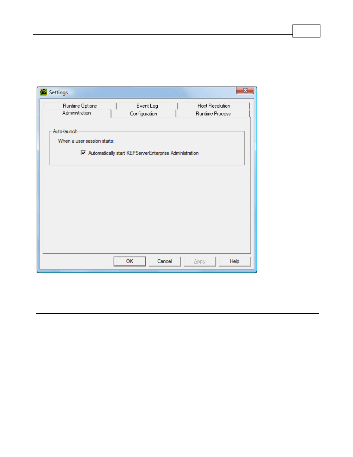
Administration
The Administration tab is used to configure the Runtime Administration's actions. When Auto Launch is checked, the
Administration will start automatically and an icon will appear in the System Tray.
Note: The Administration is a system tray application that allows quick links to various server tools including the
Runtime Settings Console, Configuration, Licensing Utility, User Manager Console and controls for stopping and starting
the Runtime service.
Runtime Settings - Configuration
The Configuration tab is used to configure how the Configuration both connects to and interacts with the Runtime.
www.kepware.com
Page 14

13
KEPServerEX5 Help
Connection
For security reasons, users cannot just connect to the Runtime. Thus, the Communicate using port parameter allows
users to specify a TCP/IP port which the Runtime will open and then listen to for console connections.
Session Management
Users can manage the connection sessions so that resources aren't being used where they aren't needed. Descriptions
of the selections are as follows.
Maximum number of simultaneous connects: This setting is used to specify the number of Configuration
connections that can be made to the Runtime at one time. The range is 1 to 64. The default is 10.
Maximum idle seconds for writer before privilege demotion: This setting is used to the length of time of
stopped activity before the connected Configuration can no longer make changes. The range is 60 to 3600
seconds. The default is 900 seconds.
Maximum idle seconds before session timeout: This setting is used to set the length of time that the console
connection can sit idle before it times out. The range is 10 to 3600 seconds. The default is 60 seconds.
Runtime Settings - Runtime Process
The Runtime Process tab is used to specify the server Runtime's process mode, as well as how it utilizes the PC's
resources.
www.kepware.com
Page 15

KEPServerEX5 Help
14
Descriptions of the parameters are as follows.
Process Mode: This parameter is used to specify whether the server will be running as System Service or
Interactive. By default, the server installs and runs as System Service. Changing this setting causes all clients,
both Configuration and process, to be disconnected and the server to be stopped and restarted.
High Priority: This parameter is used set the server process priority to high. The default setting is normal. When
checked, this setting allows the server to have priority access to resources.
Note: Microsoft recommends against setting applications to a high priority as it can adversely affect other
applications running on the same PC.
Process Affinity: This parameter is used to specify which CPUs the server can be executed on when it is run on
PCs containing more than one.
Runtime Settings - Runtime Options
The Runtime Options tab is used to change settings in the project that's being executed in the Runtime.
www.kepware.com
Page 16

15
KEPServerEX5 Help
Descriptions of the parameters are as follows:
OPC Connection Security: This parameter allows users to select authentication and also launch and access
security requirements through the DCOM Configuration Utility. In addition, users can both specify the level of
security to implement and restrict access for certain users and/or applications.
When this setting is disabled, the server will override the DCOM settings set for the application and will not
perform any authentication on the calls received from client applications. It will impersonate the security of the
client when performing any actions on behalf of the client application. Disabling this setting provides the lowest
level of security and is not recommended. If this setting is chosen, users should ensure that the client and server
applications are running in a secure environment so that the application is not compromised.
Backup the runtime project prior to replacement: This parameter enables the Runtime project to be backed
up before it is overwritten. The backup's location will be displayed in the Event Log. This option is enabled by
default.
Note: The Runtime project will be overwritten if either New or Open is selected while connected to the Runtime.
In addition, connecting to the Runtime while working offline with a project may result in Runtime project
replacement.
Keep the most recent: This parameter limits the number of backup files that will be saved to disk. The range is
1 to 1000. The default is 10.
Clean up now: This parameter invokes a confirmation dialog that allows users to delete all the Runtime project
backups. Doing so will not affect the current running project.
Allow clients to write to system level tags controls Write access to System Tags on a given device. In some
cases, users may not want a client application to have the ability to turn a device on or off in the project. This
setting applies to all system level tags. This option is disabled by default.
Runtime Settings - Event Log
The Event Log tab is used to define whether or not a Runtime log file is kept; and, if so, where and how many events
www.kepware.com
Page 17
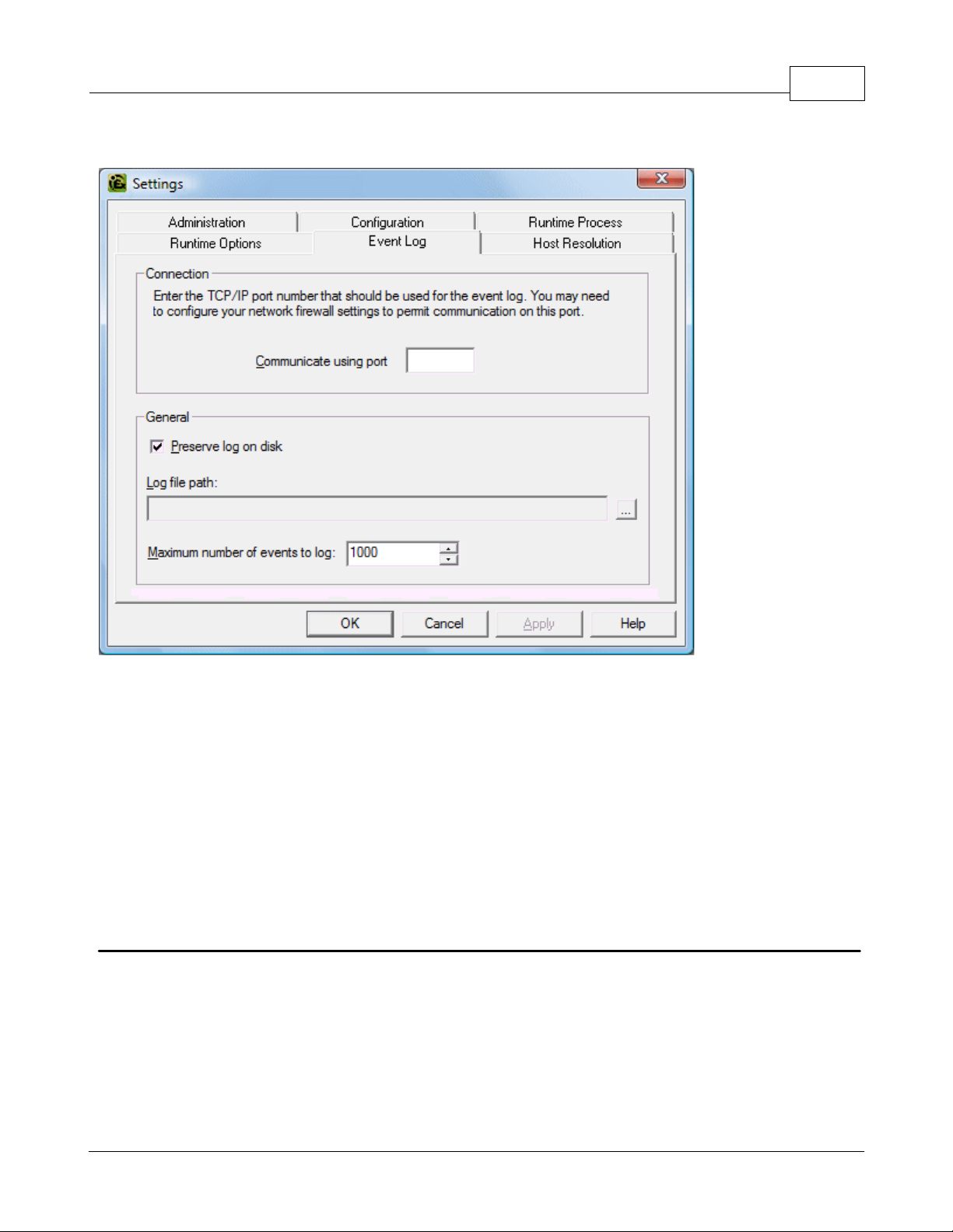
are logged into it.
KEPServerEX5 Help
16
Descriptions of the parameters are as follows.
Preserve log on disk: This parameter enables the use of a disk-based log file. When enabled, all events in the
server will be maintained on disk from one run to the next. If disabled, the server's event logging system will be
recorded in memory and no disk log will be generated. When disabled, the event log contents will be emptied
each time the server is run.
Log file path: This parameter specifies where the log file will be stored its preservation is enabled.
Maximum number of events: This parameter determines the number of records the log system will hold before
the Log Full action comes into effect. The valid range is 100 to 30000 records. The default value is 1000 records.
If users attempt to change this parameter to a value that is less than the current number of records in the log,
they will receive a warning that log file truncation will occur.
Note: The Event Log System would be useless if there was no mechanism to protect its contents. If operators could
change these parameters or reset the log, the purpose would be lost. Utilize the User Manager to limit what functions
an operator can access.
Runtime Settings - Host Resolution
The Host Resolution tab is used to specify how the server manages Host Name Resolution with Ethernet drivers that
support the use of host names for connectivity.
www.kepware.com
Page 18

17
KEPServerEX5 Help
Descriptions of the parameters are as follows.
Cache Lifetime: This parameter is used to determine how long the server will keep the resolved addresses from
host names. The server caches network addresses that it has resolved from host name requests for a period of
time to improve performance when the same address is requested repeatedly. The period is 30 to 7200 seconds.
The default is 30 seconds.
Request Pool: This parameter is used to specify how many simultaneous requests for Host Name Resolution can
be processed at one time. It allows multiple Ethernet drivers to process at the same time and also manages the
resources that are used to resolve host names. The range is 1 to 8 requests. The default is 4.
Tag Management
The server's new user-defined tag management features can be used to create a tag database structure that fits an
application's specific nature. Multiple tag groups can be defined to segregate the tag data on a device-by-device basis.
Drag and drop editing makes adding large numbers of tags easy. Additionally, CSV import and export allows tag editing
to be done in any application needed. Like all other server features, new tags can be added to the application at any
time.
Automatic Tag Database Generation
The OPC server supports the automatic generation of tags for select communication drivers. The Automatic Tag
Database Generation feature brings OPC technology one step closer to Plug and Play operation. Drivers that support
this feature can either Read tag information directly from a device or generate tags from stored tag data. In either
case, the user no longer needs to manually enter OPC tags into the server.
System Tags
System Tags are used to provide general error feedback to client applications, allow operation control over when a
device is actively collecting data and allow the standard parameters of a either a channel or device to be changed from
an OPC client application. The number of System Tags available at either the channel or device-level varies depending
on the nature of the driver being used. The System Tag can also be grouped according to their purpose as both status
and control or parameter manipulation.
www.kepware.com
Page 19

KEPServerEX5 Help
18
Property Tags
Tag Properties are available as additional tags that can be accessed by any Data Access client by appending the
property name to any fully qualified tag address. When using an OPC client that supports item browsing, users can
browse tag properties by turning on Include tag properties when a client browses the server under OPC
Settings. See Also: OPC Settings Options.
Statistics Tags
Statistics Tags are used to provide feedback to client applications regarding the operation of the channel
communications in the server. When diagnostics are enabled, there are seven built-in statistics tags available. See
Also: OPC Diagnostics Window.
Automatic OPC Tag Database Generation
This server's Automatic OPC Tag Database Generation features have been designed to make setting up the OPC
application a plug and play operation. Communications drivers that support this feature can be configured to
automatically build a list of OPC tags within the server that correspond to device-specific data. The automatically
generated OPC tags can then be browsed from the OPC client. The OPC tags that are generated depend on the nature
of the supporting driver.
If the target device supports its own local tag database, the driver will read the device's tag information and then use
the data to generate OPC tags within the server. If the device does not natively support its own named tags, the driver
will create a list of tags based on driver-specific information. An example of these two conditions is as follows:
1. If a data acquisition system supports its own local tag database, the communications driver will use the tag
names found in the device to build the server's OPC tags.
2. If an Ethernet I/O system supports detection of its own available I/O module types, the communications driver
will automatically generate OPC tags in the server that are based on the types of I/O modules plugged into the
Ethernet I/O rack.
Automatic tag database generation's mode of operation is completely configurable. Parameters set in the following
dialog allows users to configure how the server and its associated communications driver will handle automatic OPC tag
database generation.
The Automatic tag database generation on device startup setting is used to configure when OPC tags will be
www.kepware.com
Page 20

19
automatically generated. Descriptions of the selections are as follows.
Note: The Auto-Create button will be disabled when the Configuration edits a project offline.
When the option to automatically generate OPC tags is selected, any tags that are added to the server's tag space must
be saved with the project. Users can configure the project to auto save from the Tools | Options menu.
KEPServerEX5 Help
Do not generate on startup, the default condition, prevents the driver from adding any OPC tags to the tag
space of the server.
Always generate on startup causes the driver to evaluate the device for tag information and to add OPC tags
to the tag space of the server every time the server is launched.
Generate on first startup causes the driver to evaluate the target device for tag information the first time the
project is run and add any OPC tags to the server tag space as needed.
Perform the Following Action
When automatic OPC tag database generation is enabled, the server needs to know what to do with OPC tags that it
may have added from a previous run or with OPC tags that have been added or modified after the communications
driver added them originally. The Perform the following action setting is used to control how the server handles OPC
tags that were automatically generated and currently exist in the project. This feature also prevents automatically
generated tags from accumulating in the server.
For example, review the Ethernet I/O example mentioned above. If users continued to change the I/O modules in the
rack with the server configured to Always generate new OPC tags on startup, new tags would be added to the
server every time the communications driver detected a new I/O module. If the old tags were not removed, many
unused tags could accumulate in the server's tag space. The Perform the following action setting allows users to
tailor the server's operation to best fit the application's needs. Descriptions of the selections are as follows.
1. Delete on create, the default condition, deletes any tags that had previously been added to the tag space
before the communications driver adds any new tags.
2. Overwrite as necessary instructs the server to remove only those tags that the communications driver is
replacing with new tags. Any tags that are not being overwritten will remain in the server's tag space.
3. Do not overwrite prevents the server from removing any tags that had been previously generated or may have
already existed in the server. With this selection, the communications driver can only add tags that are
completely new.
4. Do not overwrite, log error has the same effect as the third; however, in addition, an error message will be
posted to the server's event log when a tag overwrite would have occurred.
Note: Removing OPC tags affects tags that have been automatically generated by the communications driver as well as
any tags that have been added using names that match generated tags. It is recommended that users avoid adding
tags to the server using names that match tags that may be automatically generated by the driver.
The parameter Add generated tags to the following group can be used to keep automatically generated tags from
mixing with tags that have been entered manually. This parameter is used to specify a subgroup that will be used when
adding all automatically generated tags for this device. The name of the subgroup can be up to 256 characters in
length. The following screens demonstrate how this parameter works, i.e., where automatically generated tags are
placed in the server's tag space. As shown below, this parameter provides a root branch to which all automatically
generated tags will be added.
www.kepware.com
Page 21
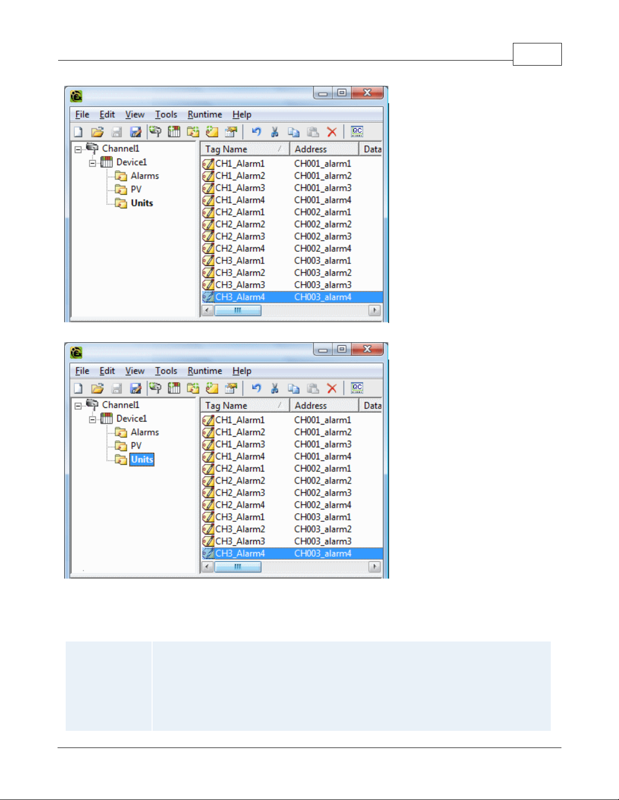
The Add generated tags to the following group was left blank.
Checked (default)
The server will automatically generate the device's tags and organize them into subgroups. In
the server project, the resulting tags will retain their tag names.
KEPServerEX5 Help
20
"MyGroup" was entered in the Add generated tags to the following group field.
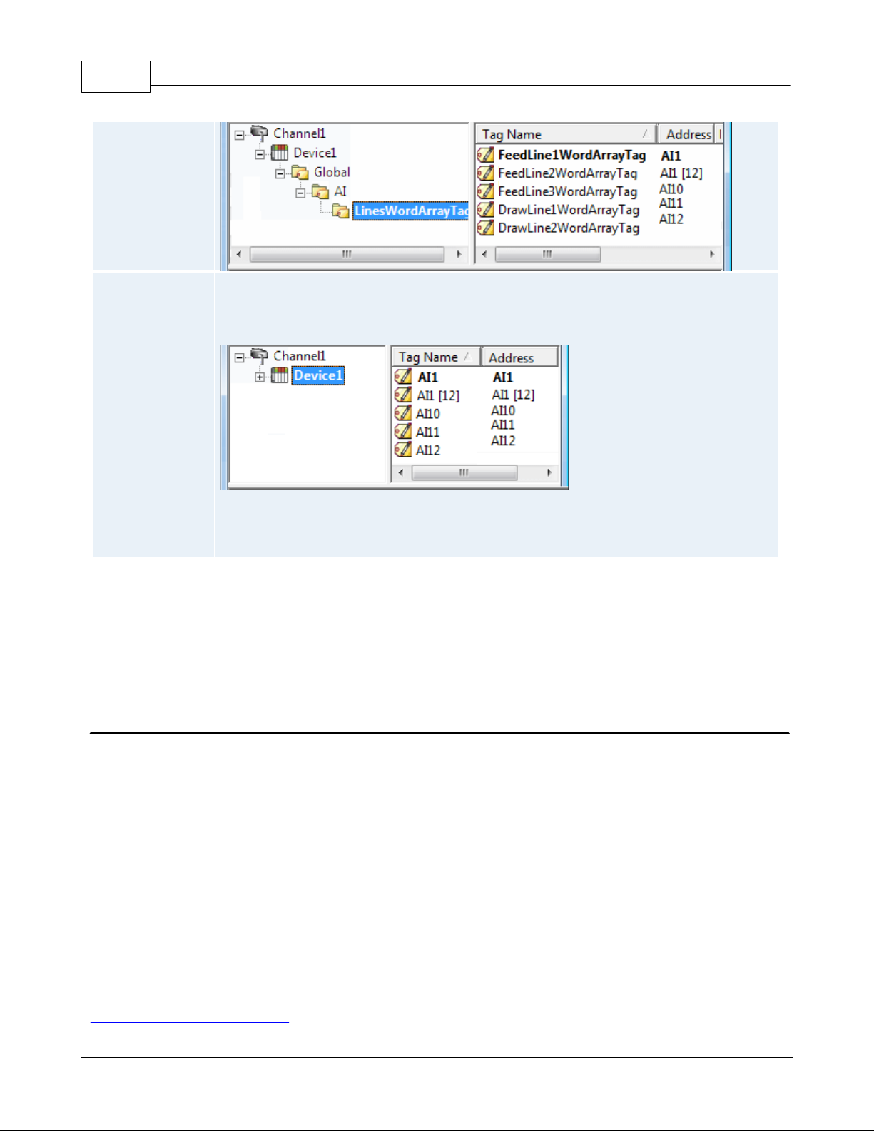
Allow Automatically Generated Subgroups
The Allow automatically generated subgroups setting controls whether or not the server automatically creates
subgroups for the automatically generated tags.
www.kepware.com
Page 22
21
Unchecked
The server will automatically generate the device's tags in a simple list without any
subgrouping. In the server project, the resulting tags will be named with the address value.
For example, the tag names will not be retained during the generation process. The image
below shows how the tag names were created using the tag's address.
Note: If, as the server is generating tags, a tag is assigned the same name as an existing tag,
the system will automatically increment to the next highest number so that the tag name is not
duplicated. For example, if the generation process were to create a tag named AI22 but there
already existed a tag with that name, it would create the tag as AI23 instead.
KEPServerEX5 Help
Auto Create
Auto Create is used to manually initiate the creation of automatically generated OPC tags. If the device's configuration
has been modified, clicking Auto Create will force the communications driver to reevaluate the device for possible tag
changes. Auto Create can be accessed from the System Tags for this device, which allows OPC client application to
initiate tag database creation.
Note: With the server's online full-time operation, these parameters can be changed at any time. Utilize the User
Manager to restrict access rights to server features in order to prevent operators from changing the parameters.
System Tags
System Tags are used to provide general error feedback to client applications, to allow operational control when a
device is actively collecting data and to allow the standard parameters of a either a channel or device to be changed by
an OPC client application when needed.
System Tags
The number of system tags available at both the channel-level or device-level varies depending on the nature of the
driver being used. In addition, application-level system tags allow client applications to monitor the server's status.
System tags can also be grouped according to their purpose as both status and control or parameter manipulation.
Parameter Control Tags
While the standard system tags provide needed feedback on server operation, the parameter control tags provide the
most powerful feature. Parameter control tags can be used to modify the operational characteristic of the server
application. This provides a great deal of flexibility in the OPC applications. By using the parameter control tags, users
can implement redundancy by switching communications links or changing the Device ID of a target device. Users can
also provide access to the tags through special supervisory screens that allow a plant engineer to make changes to the
communication parameters of the server if needed.
The tables below include descriptions of the following:
Application-Level System Tags
www.kepware.com
Page 23

KEPServerEX5 Help
Tag
Description
_ActiveTagCount
Class: Status Tag
The _ActiveTagCount is a tag that indicates the number of tags that are
currently active in the server.
This is a Read Only tag.
_ClientCount
Class: Status Tag
The _ClientCount is a tag that indicates the number of clients that are
currently connected to the server.
This is a Read Only tag.
_Date
Class: Status Tag
The _Date is a tag that indicates the current date of the system that
the server is running on. The format of this string is defined by the
operating system date/time settings.
This is a Read Only tag.
_DateTime
Class: Status Tag
The _DateTime is a tag that indicates the GMT date and time of the
system that the server is running on. The format of the string is '200405-21T20:39:07.000'.
This is a Read Only tag.
_DateTimeLocal
Class: Status Tag
The _DateTimeLocal is a tag that indicates the localized date and time
of the system that the server is running on. The format of the string is
'2004-05-21T16:39:07.000'.
This is a Read Only tag.
_FullProjectName
Class: Status Tag
The _FullProjectName is a tag that indicates the fully qualified path and
file name to the currently loaded project.
This is a Read Only tag.
_ProjectName
Class: Status Tag
The _ProjectName is a tag that indicates the currently loaded project
file name and does not include path information.
This is a Read Only tag.
_Time
Class: Status Tag
The _Time is a tag that indicates the current time of the system that
the server is running on. The format of this string is defined by the
operating system date/time settings.
This is a Read Only tag.
_TotalTagCount
Class: Status Tag
The _TotalTagCount is a tag that indicates the total number of tags that
are currently being accessed. These tags can be active or inactive.
Note: This count does not represent the number of tags configured in
the project.
This is a Read Only tag.
Tag
Description
_AvailableNetworkAdapters
Class: Parameter Tag
The _AvailableNetworkAdapters is a tag that lists the available NICs
and will include both unique NIC cards and NICs that have multiple IPs
assigned to them. Additionally this tag will also display any WAN
connections that are active, such as a dialup connection. This tag is
provided as a string tag and can be used to determine the network
Channel-Level System Tags / Serial
Channel-Level System Tags / Ethernet
Device-level System Tags / Serial and Ethernet
Application-Level System Tags
Syntax Example: <Channel Name>.<Device Name>._System._ActiveTagCount
22
Channel-level System Tags for Serial Port Driver
Syntax Example: <channel name>._System._BaudRate
www.kepware.com
Page 24

23
adapters available for use on this PC. The string returned will contain all
of the NIC names and their IP assignments. A semicolon will separate
each unique NIC in order to allow the names to be parsed within an
OPC application. For a serial driver this tag will only be used if Ethernet
Encapsulation is selected.
This is a Read Only tag.
_NetworkAdapter
Class: Parameter Tag
The _NetworkAdapter tag is a tag that allows the current NIC adapter
in use by the driver to be changed on the fly. As a string tag, the name
of the newly desired NIC adapter must be written to this tag in string
format. The string written must match the exact description of the
desired NIC in order for the change to take effect. NIC names can be
obtained from the _AvailableNetworkAdapters tag listed above. For a
serial driver, this tag will only be used if Ethernet Encapsulation is
selected.
Note: When changing the NIC selection the driver will be forced to
break all current device connections and reconnect.
This is a Read/Write tag.
_ComId
Class: Parameter Tag
The _ComId tag is a tag that allows the comm port selection for the
driver to be changed on the fly. As a string tag, the desired comm port
must be written to the tag as a string value using the following possible
selections: COM 1, COM 2 COM 3, COM 4, - - -, COM 16, and Ethernet
Encapsulation. When selecting Device Properties - Ethernet
Encapsulation mode, users will also need to set the IP number of the
remote terminal server. This is done at the device-level and will be
shown below.
This is a Read/Write tag.
_BaudRate
Class: Parameter Tag
The _BaudRate tag is a tag that allows the baud rate of the driver to be
changed on the fly. The _BaudRate tag is defined as a long value and
therefore new baud rates should be written in this format. Valid baud
rates are as follows: 300, 600, 1200, 2400, 4800, 9600, 19200,
38400, 56000, 56700, 115200, 128000 and 256000.
This is a Read/Write tag.
_Parity
Class: Parameter Tag
The _Parity tag is a tag that allows the parity of the driver to be
changed on the fly. As a string tag, the desired parity setting must be
written to the tag as a string value using the following possible
selections: None, Odd and Even.
This is a Read/Write tag.
_DataBits
Class: Parameter Tag
The _DataBits tag is a tag that allows the data bits of the driver to be
changed on the fly. The _DataBits tag is defined as a signed 8 bit value.
Valid data bits selections are 5, 6, 7 and 8.
This is a Read/Write tag.
_StopBits
Class: Parameter Tag
The _StopBits tag is a tag that allows the stop bits of the driver to be
changed on the fly. The _StopBits tag is defined as a signed 8 bit value.
Valid data bit selections are 1 and 2.
This is a Read/Write tag.
_FlowControl
Class: Parameter Tag
The _FlowControl tag is a tag that allows the flow control setting of the
driver to be changed on the fly. As a string tag, the desired flow control
setting must be written to the tag in this format. Possible selections for
flow control include: None, DTR, RTS, "DTR,RTS", RTS Always and RTS
Manual. Not all drivers support the RTS Manual mode of operation.
This is a Read/Write tag.
_RtsLineRaise
Class: Parameter Tag
The _RtsLineRaise tag is a tag that allows the RTS Line to be raised for
a user-selected period of time before the driver attempts to transmit a
message. This tag will only be effective for drivers that support Manual
KEPServerEX5 Help
www.kepware.com
Page 25

KEPServerEX5 Help
RTS mode. The _RtsLineRaise is defined as a long value. The valid
range is 10 - 2550 milliseconds. The Manual RTS mode has been
designed for use with radio modems.
This is a Read/Write tag.
_RtsLineDrop
Class: Parameter Tag
The _RtsLineDrop tag is a tag that allows the RTS Line to be lowered
for a user-selected period of time after the driver attempts to transmit
a message. This tag will only be effective for drivers that support
Manual RTS mode. The _RtsLineDrop is defined as a long value. The
valid range is 0 - 2550 milliseconds. The Manual RTS mode has been
designed for use with radio modems.
This is a Read/Write tag.
_RtsLinePollDelay
Class: Parameter Tag
The _RtsLinePollDelay tag is a tag that allows a user-configurable pause
to be placed after each message sent from the driver. This tag will only
be effective for drivers that support Manual RTS mode. The
_RtsLinePollDelay is defined as a long value. The valid range is 0 2550 milliseconds. The Manual RTS mode has been designed for use
with radio modems.
This is a Read/Write tag.
_ReportComErrors
Class: Parameter Tag
The _ReportComErrors tag is a tag that allows the reporting of low level
communications errors such as parity and framing errors to be enabled
or disabled. This tag is defined as a Boolean tag and can be set either
true or false. When true, the driver will report any low-level
communications error to the server event system. When set false the
driver will ignore the low-level communications errors and not report
them. The driver will still reject a communications transaction if it
contains errors. If the environment contains a lot of electrical noise,
this feature can be disabled to prevent the event log from filling with
error messages.
This is a Read/Write tag.
_EnableDiagnostics
Class: Parameter Tag
The _EnableDiagnostics tag is a tag that allows the diagnostic system of
the driver to be enabled and disabled. The diagnostic system places a
little additional burden on the driver while enabled. As such the server
allows diagnostics to be enabled or disabled to improve the driver's
performance. When disabled, the Diagnostics Tags will not be
available.
This is a Read/Write tag.
_WriteOptimizationDutyCycle
Class: Parameter Tag
The _WriteOptimizationDutyCycle tag is a tag that allows the duty cycle
of the Write to Read ratio to be changed on the fly. The duty cycle
controls how many Writes the driver will do for each Read it performs.
The _WriteOptimizationDutyCycle is defined as an unsigned long value.
The valid range is 1 to 10 Write per Read.
See Also: Channel Properties: Write Optimizations.
This is a Read/Write tag.
Tag
Description
_AvailableNetworkAdapters
Class: Parameter Tag
The _AvailableNetworkAdapters is a tag that lists the available NICs
and will include both unique NIC cards and NICs that have multiple IPs
assigned to them. Additionally this tag will also display any WAN
connections that are active, such as a dialup connection. This tag is
provided as a string tag and can be used to determine the network
adapters available for use on this PC. The string returned will contain all
of the NIC names and their IP assignments. A semicolon will separate
each unique NIC in order to allow the names to be parsed within an
OPC application. For a serial driver, this tag will only be used if Ethernet
24
Channel-level System Tags for Ethernet Drivers
Syntax Example: <channel name>._System._NetworkAdapter
www.kepware.com
Page 26

25
Encapsulation is selected.
This is a Read Only tag.
_NetworkAdapter
Class: Parameter Tag
The _NetworkAdapter tag is a tag that allows the current NIC adapter
in use by the driver to be changed on the fly. As a string tag, the name
of the newly desired NIC adapter must be written to this tag in string
format. The string written must match the exact description of the
desired NIC in order for the change to take effect. NIC names can be
obtained from the _AvailableNetworkAdapters tag listed above. For a
serial driver, this tag will only be used if Ethernet Encapsulation is
selected.
Note: When changing the NIC selection, the driver will be forced to
break all current device connections and reconnect.
This is a Read/Write tag.
_EnableDiagnostics
Class: Parameter Tag
The _EnableDiagnostics tag is a tag that allows the diagnostic system of
the driver to be enabled and disabled. The diagnostic system places a
little additional burden on the driver while enabled. As such the server
allows diagnostics to be enabled or disabled to improve the driver's
performance. When disabled the Diagnostics Tags will not be
available.
This is a Read/Write tag.
_WriteOptimizationDutyCycle
Class: Parameter Tag
The _WriteOptimizationDutyCycle tag is a tag that allows the duty cycle
of the Write to Read ratio to be changed on the fly. The duty cycle
controls how many Writes the driver will do for each Read it performs.
The _WriteOptimizationDutyCycle is defined as an unsigned long value.
The valid range is 1 to 10 Write per Read.
See Also: Channel Properties: Write Optimizations.
This is a Read/Write tag.
Tag
Description
_DeviceId
Class: Parameter Tag
The _DeviceId tag is a tag that allows the ID of the device to be
changed on the fly. The data format of the _DeviceId depends on the
type of device. For most serial devices this tag will be a Long data type.
For Ethernet drivers the _DeviceId will be formatted as a string tag,
allowing the entry of an IP address. In either case, writing a new
Device ID to this tag will cause the driver to change the target field
device. This will only occur if the Device ID written to this tag is
correctly formatted and within the valid range for the given driver.
This is a Read/Write tag.
_ConnectTimeout
Class: Parameter Tag
The _ConnectTimeout is a tag that allows the timeout associated with
making an IP connection to a device to be changed on the fly. This tag
is available when either a native Ethernet driver is in use or a Serial
driver is in Ethernet Encapsulation mode. The _ConnectTimeout is
defined as a Long data type. The valid range is 1 to 30 seconds.
This is a Read/Write tag.
_RequestTimeout
Class: Parameter Tag
The _RequestTimeout is a tag that allows the timeout associated with a
data request to be changed on the fly. The _RequestTimeout tag is
defined as a Long value. The valid range is 100 to 30000 milliseconds.
This parameter tag applies to all drivers equally.
This is a Read/Write tag.
_RequestAttempts
Class: Parameter Tag
The _RequestAttempts is a tag that allows the number of retry
attempts to be changed on the fly. The _RequestAttempts is defined as
a Long value. The valid range is 1 to 10 retries. This parameter tag
KEPServerEX5 Help
Device-level System Tags for both Serial and Ethernet Drivers
Syntax Example: <Channel Name>.<Device Name>._System._Error
www.kepware.com
Page 27

KEPServerEX5 Help
applies to all drivers equally.
This is a Read/Write tag.
_InterRequestDelay
The _InterRequestDelay is a tag that allows the time interval between
device transactions to be changed on the fly. The _InterRequestDelay is
defined as a Long data type. The valid range is 0 to 30000 milliseconds.
This parameter tag only applies to drivers that support this feature.
This is a Read/Write tag.
_EncapsulationIp
Class: Parameter Tag
The _EncapsulationIp tag allows the IP of a remote terminal server to
be specified and changed on the fly. This parameter tag is only
available on serial drivers that support Device Properties - Ethernet
Encapsulation mode. The _EncapsulationIp is defined as a string data
type, allowing the entry of an IP address number. The server will reject
entry of invalid IP addresses. This tag is only valid for a Serial driver in
Ethernet Encapsulation mode.
This is a Read/Write tag.
_EncapsulationPort
Class: Parameter Tag
The _EncapsulationPort tag allows the port number of the remote
terminal server to be specified and changed on the fly. The
_EncapsulationPort is defined as a long data type. The valid range is 0
to 65535. The port number entered in this tag must match that of the
desired remote terminal server for proper Ethernet Encapsulation to
occur. This tag is only valid for a Serial driver in Ethernet Encapsulation
mode.
This is a Read/Write tag.
_EncapsulationProtocol
Class: Parameter Tag
The _EncapsulationProtocol tag allows the IP protocol used for Ethernet
Encapsulation to be specified and changed on the fly. The
_EncapsulationProtocol is defined as a string data type. Writing either
"TCP/IP" or "UDP" to the tag specifies the IP protocol. The protocol
used must match that of the remote terminal server for proper
Ethernet Encapsulation to occur. This tag is only valid for a Serial driver
in Ethernet Encapsulation mode.
This is a Read/Write tag.
_AutoCreateTagDatabase
Class: Parameter Tag
The _AutoCreateTagDatabase tag is a Boolean tag that is used to
initiate the automatic OPC tag database functions of this driver for the
device to which this tag is attached. When this tag is set TRUE, the
communications driver will attempt to automatically generate an OPC
tag database for this device. This tag will not appear for drivers that do
not support Automatic OPC Tag Database Generation.
This is a Read/Write tag.
_Enabled
Class: Parameter Tag
The _Enabled tag is a Boolean tag that allows the active state of the
device to be turned On or Off. When this tag is set FALSE, all other
user-defined tags and data from this device will be marked as invalid
and Writes will not be accepted for the device. When this tag is set
TRUE, normal communications will occur with the device.
This is a Read/Write tag.
_Error
Class: Status Tag
The _Error tag is a Boolean tag that returns the current error state of
the device. When FALSE, the device is operating properly. When set
TRUE, the driver has detected an error when communicating with this
device. A device enters an error state if it has completed the cycle of
request timeouts and retries without a response.
See Also: Device Properties - Timing.
This is a Read Only tag.
_NoError
Class: Status Tag
The _NoError tag is a Boolean tag that returns the current error state
of the device. When TRUE, the device is operating properly. When
FALSE, the driver has detected an error when communicating with this
device. A device enters an error state if it has completed the cycle of
26
www.kepware.com
Page 28

27
request timeouts and retries without a response.
See Also: Device Properties - Timing.
This is a Read Only tag.
_Simulated
Class: Status Tag
The _Simulated tag is a Boolean tag that provides feedback about the
simulation state of the current device. When Read as TRUE, this device
is in a simulation mode. While in simulation mode, the server will return
good data for this device but will not attempt to communicate with the
actual physical device. When tag is Read as FALSE, communication with
the physical device will be active.
This is a Read Only tag.
_AutoDemoted
The _AutoDemoted tag is a Boolean tag that returns the current autodemoted state of the device. When FALSE, the device is not demoted
and is being scanned by the driver. When set TRUE, the device is in
demoted and not being scanned by the driver.
This is a Read Only tag.
_AutoDemotionEnabled
The _AutoDemotionEnabled tag is a Boolean tag that allows the device
to be automatically demoted for a specific time period when the device
is nonresponsive. When this tag is set FALSE, the device will never be
demoted. When this tag is set TRUE, the device will be demoted when
the _AutoDemotedFailureCount has been reached.
This is a Read/Write tag.
_AutoDemotedFailureCount
The _AutoDemotedFailureCount tag specifies how many successive
failures it takes to demote a device. The _AutoDemotedFailureCount is
defined as a long data type. The valid range is 1 to 30. This tag can
only be written to if _AutoDemotionEnabled is set to TRUE.
This is a Read/Write tag.
_AutoDemotionIntervalMS
The _AutoDemotionIntervalMS tag specifics how long, in milliseconds, a
device will be demoted before re-attempting to communicate with the
device. The _AutoDemotionIntervalMS is defined as a long data type.
The valid range is 100 to 3600000 milliseconds. This tag can only be
written to if _AutoDemotionEnabled is set to TRUE.
This is a Read/Write tag.
_AutoDemotionDiscardWrites
The _AutoDemotionDiscardWrites tag is a boolean tag that specifies
whether or not Write requests should be discarded during the demotion
period. When this tag is set to FALSE, all Writes requests will be
performed regardless of the _AutoDemoted state. When this tag is set
to TRUE, all Writes will be discarded during the demotion period.
This is a Read/Write tag.
KEPServerEX5 Help
When using an OPC client, the system tags will be found under the _System branch of the server browse space for a
given device. The following image taken from the supplied OPC Quick Client shows how the system tags appear to an
OPC client.
www.kepware.com
Page 29

KEPServerEX5 Help
Tag Name
Description
_Name
The _Name property tag indicates the current name for the tag it is
referencing.
28
The _System branch found under the DeviceName branch is always available. If referencing a system tag from a DDE
application given the above example and the DDE defaults, the link would appear as follows:
= <DDE service name>|_ddedata!Channel1.Device1._System._Error
The _Enabled tag provides a very flexible means of controlling the OPC applications. In some cases, specifically in
modem applications, it can be convenient to disable all devices except the device currently connected to the modem.
Additionally, using the _Enable tag to allow the application to turn a particular device off while the physical device is
being serviced can eliminate harmless but unwanted communications errors in the server's event log.
See Also: Statistics Tags and Property Tags.
Note: Modem Tags are described in the topics under Modem Support.
Property Tags
The Property Tags are used to provide Read Only access to Tag Properties for client applications. To access a tag
property, append the property name to the fully qualified tag address that has been defined in the server's tag
database. For more information, refer to Tag Properties.
If the fully qualified tag address is Channel1.Device1.Tag1, its description can be accessed by appending the description
property as Channel1.Device1.Tag1._Description.
Supported Property Tag Names
www.kepware.com
Page 30

29
_Address
The _Address property tag indicates the current address for the tag it is
referencing.
_Description
The _Description property tag indicates the current description for the
tag it is referencing.
_RawDataType
The _RawDataType property tag indicates the raw data type for the tag
it is referencing.
_ScalingType
The _ScalingType property tag indicates the scaling type (None, Linear
or Square Root) for the tag it is referencing.
_ScalingRawLow
The _ScalingRawLow property tag indicates the raw low range for the
tag it is referencing. If scaling is set to none this value contains the
default value if scaling was applied.
_ScalingRawHigh
The _ScalingRawHigh property tag indicates the raw high range for the
tag it is referencing. If scaling is set to none this value contains the
default value if scaling was applied.
_ScalingScaledDataType
The _ScalingScaledDataType property tag indicates the scaled to data
type for the tag it is referencing. If scaling is set to none this value
contains the default value if scaling was applied.
_ScalingScaledLow
The _ScalingScaledLow property tag indicates the scaled low range for
the tag it is referencing. If scaling is set to none this value contains the
default value if scaling was applied.
_ScalingScaledHigh
The _ScalingScaledHigh property tag indicates the scaled high range for
the tag it is referencing. If scaling is set to none this value contains the
default value if scaling was applied.
_ScalingClampLow
The _ScalingClampLow property tag indicates whether the scaled low
value should be clamped for the tag it is referencing. If scaling is set to
none this value contains the default value if scaling was applied.
_ScalingClampHigh
The _ScalingClampHigh property tag indicates wether the scaled high
value should be clamped for the tag it is referencing. If scaling is set to
none this value contains the default value if scaling was applied.
_ScalingUnits
The _ScalingUnits property tag indicates the scaling units for the tag it
is referencing. If scaling is set to none this value contains the default
value if scaling was applied.
Tag Name
Description
_SuccessfulReads
The _SuccessfulReads tag contains a count of the number of Reads this
channel has completed successfully since the start of the application or
since the last time the _Reset tag was invoked. This tag is formatted as
unsigned 32 bit integer and will eventually rollover. This tag is Read
Only.
_SuccessfulWrites
The _SuccessfulWrites tag contains a count of the number of Writes
this channel has completed successfully since the start of the
application or since the last time the _Reset tag was invoked. This tag
is formatted as an unsigned 32 bit integer and will eventually rollover.
This tag is Read Only.
_FailedReads
The _FailedReads tag contains a count of the number of Reads this
channel has failed to complete since the start of the application or since
the last time the _Reset tag was invoked. This count is only
incremented after the channel has failed the request based on the
KEPServerEX5 Help
See Also: Statistics Tags, System Tags, Modem Tags and Property Tags.
Statistics Tags
Statistics Tags are used to provide feedback to client applications regarding the operation of the channel
communications in the server. Currently there are seven built-in statistics tags available when diagnostics are enabled.
See Also: OPC Diagnostic Window.
Syntax Example: <Channel Name>._Statistics._FailedReads
Supported Statistics Tag Names
www.kepware.com
Page 31

KEPServerEX5 Help
configured timeout and retry count for the device. This tag is formatted
as an unsigned 32 bit integer and will eventually rollover. This tag is
Read Only.
_FailedWrites
The _FailedWrites tag contains a count of the number of Writes this
channel has failed to complete since the start of the application or since
the last time the _Reset tag was invoked. This count is only
incremented after the channel has failed the request based on the
configured timeout and retry count for the device. This tag is formatted
as unsigned 32 bit integer and will eventually rollover. This tag is Read
Only.
_RxBytes
The _RxBytes tag contains a count of the number of bytes the channel
has received from connected devices since the start of the application
or since the last time the _Reset tag was invoked. This tag is formatted
as unsigned 32 bit integer and will eventually rollover. This tag is Read
Only.
_TxBytes
The _TxBytes tag contains a count of the number of bytes the channel
has sent to connected devices since the start of the application or since
the last time the _Reset tag was invoked. This tag is formatted as
unsigned 32 bit integer and will eventually rollover. This tag is Read
Only.
_Reset
The _Reset tag can be used to reset all diagnostic counters. The _Reset
tag is formatted as a Boolean tag. Writing a non-zero value to the
_Reset tag will cause the diagnostic counters to be reset. This tag is
Read/Write.
_MaxPendingReads
The _MaxPendingReads tag contains a count of the maximum number
of pending read requests for the channel since the start of the
application (or the _Reset tag) was invoked. This tag is formatted as an
unsigned 32 bit integer. The tag is Read Only.
_MaxPendingWrites
The _MaxPendingWrites tag contains a count of the maximum number
of pending write requests for the channel since the start of the
application (or the _Reset tag) was invoked. This tag is formatted as an
unsigned 32 bit integer. The tag is Read Only.
_PendingReads
The _PendingReads tag contains a count of the current pending read
requests for the channel. This tag is formatted as an unsigned 32 bit
integer. The tag is Read Only.
_PendingWrites
The _PendingWrites tag contains a count of the current pending write
requests for the channel. This tag is formatted as an unsigned 32 bit
integer. This tag is Read Only.
30
Statistics Tags are only available when diagnostics are enabled. To access from an OPC client, the diagnostic tags can
be browsed from the _Statistics branch of the server browse space for a given channel. The following diagram, taken
from the supplied OPC Quick Client, shows how the Diagnostics Tag appear to an OPC client.
www.kepware.com
Page 32

31
Tag Name
Description
Access
_Dial
Writing any value to this tag initiates
dialing of the current PhoneNumber.
The Write is ignored unless the
current Status is 3 (Idle). An error is
reported if the is current phone
number has not been initialized.
Read/Write
KEPServerEX5 Help
The _Statistics branch found under the Channel branch will only appear when diagnostics are enabled for the channel.
In order to reference a Diagnostics Tag from a DDE application given the above example and the DDE defaults, the link
would appear as follows:
= <DDE service name>|_ddedata!Channel1._Statistics._SuccessfulReads
The values of the Diagnostics Tag can also be viewed directly in the server by using the Channel Diagnostics window.
If "Enable Diagnostics" has been selected under Channel Properties, right-click on that channel and then select
Diagnostics.
See Also: System Tags and Property Tags.
Note: Modem Tags are described in the topics under Modem Support.
Modem Tags
The following tags are created automatically for the channel when modem use is selected.
Syntax Example: <Channel Name>.<Device Name>._Modem._Dial
Supported Modem Tag Names
www.kepware.com
Page 33

KEPServerEX5 Help
Attempting to issue a dial command
while the Mode tag is set to 2
(incoming call only) will generate an
error.
_DialNumber
The DialNumber tag shows the phone
number that is actually dialed, after
any dialing preference translations
have been applied (such as the
addition of an area code). This tag is
intended for debugging purposes. It
can provide useful feedback to an
operator if phone numbers are
entered manually.
Read Only
_Hangup
Writing any value to this tag hangs
up the current connection. The
"Hangup" tag will also hang-up the
current connection when an external
device has called the server. Writes
to the "Hangup" tag will be ignored if
the Status <= 3 (Idle) meaning that
there is no currently open
connection.
Read/Write
_LastEvent
Whenever the Status changes, the
reason for the change is set in this
tag as a number. For a list of event
numbers and meanings, refer to Last
Event Values.
Read Only
_Mode
This allows for configuring the line
for calling only, answering only or
both.
Writing a 1 to the Mode tag sets the
line for outgoing calls only, no
incoming calls will be answered when
in this mode. Writing a 2 to the Mode
tag sets the line for incoming calls
only, requests to dial out (Writes to
the Dial tag) are ignored. The default
setting is 0, which allows for both
outgoing and incoming calls.
This value can only be changed when
the Status is <= 3 (Idle).
Read/Write
_PhoneNumber
This is the current phone number
that will be dialed. Users can Write to
this value at any time, but the
change is only effective if Status is
<= 3 (Idle). If users Write to the
phone number while the status is
greater than 3, the number will be
queued. As soon as the status drops
to 3 or less, the new number will be
transferred to the tag. The queue is
of size 1, so only the last phone
number written will be remembered.
The phone number must be in
canonical format in order to apply
the dialing preferences. If the
canonical format is used, the
resulting number that will be dialed
(after dialing preferences have been
applied) can be displayed as the
DialNumber.
Read/Write
32
www.kepware.com
Page 34

33
Canonical format is the following:
+<country code>[space](<area
code>)[space]<phone number>
example: +1 (207) 846-5881
Note: The country code for the U.S.
is 1.
If the number is not in canonical
form, dialing preferences will not be
applied. The number will be dialed
exactly as it is entered. Users can
also enter a Phonebook tag name
instead of a phone number. In this
case, the current value of the
phonebook tag will be used.
_Status
This is the current status of the
modem assigned to a channel. For a
list of status values and meanings,
refer to Status Values.
Read Only
_StringLastEvent
This contains a textual representation
of the LastEvent tag value. For a list
of event numbers and meanings,
refer to Last Event String Values.
Read Only
_StringStatus
This contains a textual representation
of the Status tag value. For a list of
event numbers and meanings, refer
to Status String Values.
Read Only
Bit
Meaning
0
Initialized with TAPI
1
Line open
2
Connected
3
Calling
4
Answering
Value
Meaning
0
Un-initialized, the channel is not usable
1
Initialized, no line open
3
Line open and the state is idle
7
Connected
11
Calling
19
Answering
Status Value
StringStatus Text
0
Uninitialized, channel is unusable
1
Initialized, no line open
3
Idle
7
Connected
KEPServerEX5 Help
Status Values
The five lowest bits of the 32 bit status variable are currently being used.
When read as an integer, the value of the status tag will always be one of the following:
Status String Values
www.kepware.com
Page 35

11
Calling
19
Answering
LastEvent
Reason for Change
-1
<blank> [no events have occurred yet]
0
Initialized with TAPI
1
Line closed
2
Line opened
3
Line connected
4
Line dropped by user
5
Line dropped at remote site
6
No answer
7
Line busy
8
No dial tone
9
Incoming call detected
10
User dialed
11
Invalid phone number
12
Hardware error on line caused line close
LastEvent
StringLastEvent
-1
<blank> [no events have occurred yet]
0
Initialized with TAPI
1
Line closed
2
Line opened
3
Line connected
4
Line dropped by user
5
Line dropped at remote site
6
No answer
7
Line busy
8
No dial tone
9
Incoming call detected
10
User dialed
11
Invalid phone number
12
Hardware error on line caused line close
13
Unable to dial
Last Event Values
KEPServerEX5 Help
34
Last Event String Values
Communications Management
Auto-Demotion
The Auto-Demotion parameters allow a driver to temporarily place a device off-scan in the event that a device is not
responding. By placing a nonresponsive device offline, the driver can continue to optimize its communications with
other devices on the same channel by stopping communications with the nonresponsive device for a specific time
period. After the specific time period has been reached, the driver will re-attempt to communicate with the
nonresponsive device. If the device is responsive, the device will be placed on-scan; otherwise, it will restart its offscan time period. See Also: Device Properties - Auto-Demotion.
Network Interface Selection
Users can select a NIC card for use with any Ethernet driver or serial driver running in Ethernet Encapsulation mode.
The Network Interface feature is used to select a specific NIC card based on either the NIC name or its currently
www.kepware.com
Page 36

35
assigned IP address. The list of available NICs will include both unique NIC cards and NICs that have multiple IPs
assigned to them. The selection will also display any WAN connections that may be active (such as a dialup connection).
KEPServerEX5 Help
Ethernet Encapsulation
The Ethernet Encapsulation mode has been designed to provide communications with serial devices connected to
terminal servers on the Ethernet network. A terminal server is essentially a virtual serial port: the terminal server
converts TCP/IP messages on the Ethernet network to serial data. Once the message has been converted to a serial
form, users can connect standard devices that support serial communications to the terminal server. Using a terminal
server device allows users to place RS-232 and RS-485 devices throughout the plant operations while still allowing a
single localized PC to access the remotely mounted devices. Furthermore, the Ethernet Encapsulation mode allows an
individual Network IP address to be assigned to each device as needed. By using multiple terminal servers, users can
access hundreds of serial devices from a single PC via the Ethernet network. For more information, refer to How Do
I.. and Device Properties - Ethernet Encapsulation.
Modem Support
This server supports the use of modems to connect to remote devices, which is established through the use of special
modem tags that become available at the channel-level when a dial-up network connection has been created. These
channel-level modem tags can be used to dial a remote device, monitor the modem status while connected and
terminate the call when completed.
Note: Not all serial drivers support the use of modems. To determine modem support, refer to the specific driver's help
documentation.
When accessing the new modem tags, the channel name can be used as either a base group or topic name. If the
project contains more than one channel definition, users will need to configure the channel names so that each is
unique. This remains true for device names, as well. Channel names can no longer match the device name when the
project needs to be configured to use a modem. The channel name requirements do not apply to projects that are not
using a modem.
In order to be used, modems need to be configured with the operating system through the Control Panel settings. For
specific setup information, refer to the Windows and modem documentation. Once the modem has been properly
installed, it can be enabled by selecting the Use Modem checkbox in the Channel Wizard.
Important: Many new commercial modems are designed to dial-up network server connections and negotiate the
fastest and clearest signal. When communicating to a serial automation device, the modem needs to connect at a
specific Baud (Bits per Second) and Parity. For this reason, we strongly recommend the use of an external modem,
which can be configured to dial using specific Baud Rate and Parity settings. To determine the best modem for a specific
application, check with Technical Support. For examples on how to use a modem in a project, refer to How Do I....
Using a Modem in the Server Project
Modems convert the serial data from the RS-232 port into signal levels that can be transmitted over the phone line. To
do this, modems break each byte of the serial data down into bits used to generate the signal to be transmitted. Most
modems can handle converting up to 10 bits of information for every byte of data that they send. To communicate with
a device via modem, it must be able to use 10 bits or less. The following formula can be used to determine how many
bits a specific device is using.
Start Bits + Data Bits + Parity + Stop Bits = Total Bit Count
For example, if using the Modbus RTU driver we can assume that the device is configured to use 8 Data Bits, Even
Parity and 1 Stop Bit (1 Start bit is always implied). When plugged into the formula, it would be 1 + 8 + 1 + 1 = 11
Bits. A normal modem would not be able to transmit data to this Modbus device using these settings. If the Parity is
changed to None, however, the result becomes 1 + 8 + 0 + 1=10 Bits. A normal modem can now be used to transmit
data to this Modbus device.
Some drivers simply cannot use a normal modem connection and cannot be configured to use a 10 bit or less data
format. These devices cannot use standard modems. Luckily, there are manufacturers who provide modems that can
handle transmitting 11 data bits. If the driver falls into this category, users should consult the device's manufacturer for
recommendations on an appropriate modem vendor. Modem operation will be enabled for all serial drivers regardless of
their suitability for modem operation.
Note: For the following example instructions, create a project and set the channel settings to use 10 bits or less for the
connection. Configure the device to use the same settings.
www.kepware.com
Page 37

KEPServerEX5 Help
36
Configuring the Initiating Modem
This server uses the Windows TAPI interface to access modems attached to the PC. The TAPI interface was designed to
provide Windows programs a common interface that could be accessed by a range of modems existing in a PC. A set of
drivers for the Windows OS, which are provided by the modem's manufacturer, must be installed before the server can
use the modem in a project. The Windows Control Panel can be used to install new modems. For information regarding
modem installation and setup, refer to both the Windows and the modem's help documentation.
Once the modem has been properly installed, users can begin using it in a server project. The receiving end, or the
device modem, needs to be properly configured before it can be used. Each driver contains a Modem Configuration
page in its help file. This page contains a listing of the receiving modem's active profile. Users will need to confirm that
the receiving modem matches the profile provided by the driver.
Configuring the Receiving Modem
Use the Hyperterminal program that is included with Windows to configure the Receiving Modem easily. For more
information, follow the instructions below.
1. Use an available Serial Port to connect the desired receiving modem to the PC. Start Hyperterminal and then open
a new connection. Name the new connection ModemSetup.
2. In the invoked Connect To dialog, click in the Connect Using drop-down menu and select the communication port
to which the receiving modem is attached. Although other modems may appear in this list, they should be ignored for
the moment.
3. In the COMx Properties dialog, configure the communications port settings that will be used to talk to the receiving
modem.
Important: The COMx Properties settings must match the Baud Rate, Data Bits, Parity and Stop Bits used by the
target device. Modems remember the Baud Rate, Data Bits, Parity and Stop Bits that were used to talk to it last; thus,
if the receiving modem was configured at 19,200 baud but the device was configured for 9600 baud, the modem will
never be able to speak to the device. Although it could connect, the receiving modem would send all the data to the
device at 19,200 baud. This is true even if the modem connects at 9600 baud or if the transmitting modem is being
spoken to at 9600 baud. Any disparity between the settings will cause the modem application to fail. To avoid the error,
match the settings between the newly created server project and one that has a direct cable connection.
4. Next, enter the port settings. Then, click OK.
Note: At this point, users should be able to issue commands to the receiving modem. On many modems, this can be
tested by typing ATI4 followed by Enter. To ensure this is a valid test for a specific modem, refer to its help
documentation. If the modem is properly attached to the PC it will respond by displaying its current profile settings.
5. Set the receiving modem's desired profile and then save the settings by issuing a write command to the modem. To
do so, type AT&W0 followed by Enter. To test the receiving modem's configuration afterwards, simply turn it off for a
moment and then turn it back on. Next, type AT14 followed by Enter (or another applicable command). The modem
should display its current profile, including any changes that have been made.
Important: The profile settings and reference documents provided here are to be used as examples. Because of
different configuration commands and codes that may be used among modem manufacturers, refer to the specific help
documentation to verify all settings.
Cables
Before the project is ready to be used, users need to configure the correct cable connection between the receiving
modem and the device. There are 3 cables necessary for this: the existing device communication cable for direct
connection, a NULL modem adapter and a NULL modem cable. A NULL modem cable, in which all the pins are
connected to the same pins on both ends of the cable, is connected to the modem. The device communication cable,
used to connect to the target device, usually has pins 2 and 3 reversed. Since the cable being used to talk to the device
for the direct connection is obviously working properly by this point, users can use it on the receiving modem by
attaching a NULL modem adapter. Similarly, a PC modem cable will run from the PC to the initiating modem. With the
cables in place, users are now ready to use a modem in their application.
Note: NULL modem adapters can be found at most computer stores.
Example: Server Side Modem Configuration
After the modems have been properly configured and installed, users can enable their use with the server. At this point,
users should refer back to the direct connect project completed earlier when testing the device configuration and
communications.
www.kepware.com
Page 38

37
Data Type
Privilege
String
Read/Write
1. Load the direct connect project and then double-click on the Channel Name. This will invoke the current direct
connect settings for Baud Rate, Parity and etc.
2. Select the Use Modem checkbox. The settings on this page should now become unavailable.
3. Next, click on the Modem tab to display the list of modems available on the computer.
Note: If there are no modems visible on list, users will need to exit the server and attempt to reinstall the modem
using the Modem Configuration tools supplied with the operating system.
4. Select the modem that will be used with the server project. At this point, the Dialing... and Properties... buttons
should become available. Select Properties...
Note: The Properties dialog is used to configure the initiating modem's characteristics. There are two sections available:
5. Next, click the Advanced... button.
Note: The Advanced Connection dialog is used to configure error correction and flow control for the initiating
modem. For more information about recommended settings, refer to the specific driver's help documentation. In most
cases, Error Correction and Data Compression can be enabled; Flow Control can be either enabled or disabled,
depending.
6. Next, click OK in each dialog until returned to the modem list within the server. When editing an existing project,
users can click OK. When editing a new project, users can click Next. If, at this point, an existing direct connect project
has just been edited, the server project is now ready for modem operation.
7. Save the project.
KEPServerEX5 Help
General is used to set connection speed and speaker volume. The connection speed should be set to match the
speed used by the target device when this was a direct connect project.
Connection is used to configure Data Bits, Parity and Stop Bits. These settings should be set to match the target
device settings.
Using a Modem in Your Application
Once modem operation has been enabled for the driver, a list of predefined tags became available in the driver's Tag
Window. These Modem Tags are contained under the Channel Name, which has become an active OPC Access path used
to access the Modem Tags. The Modem Tags are used to control and monitor an attached modem. Operationally, the
server knows very little about what the application needs for modem control; thus, the server does not imply any type
of control over it. By using the predefined Modem Tags, users can apply the application's control or scripting capabilities
to control the server's use of the selected modem.
Phonebook Tags
A Phonebook Tag can be used in place of specifying a telephone number by directly writing to the PhoneNumber tag. A
phonebook tag can be created on the channel, along with the other modem system tags previously described. The data
associated with a Phonebook tag is a phone number that can be assigned when the tag is created and/or later modified
when the server has an active client connection. The phone number stored in a phonebook tag can be used to dial by
simply writing anything to the tag. The act of writing will cause the selected phonebook tag to dial.
Syntax Example: <Channel Name>._Phonebook.<Phonebook Tag Name>
Phonebook Tags are entered using the dialog shown below.
www.kepware.com
Page 39

KEPServerEX5 Help
Tag Name
Description
Access
<Name of Phone
book tag created in
Modem
Configuration>
Instead of specifying a telephone number by directly writing to the PhoneNumber
tag, a phonebook tag can be used. A phonebook tag can be created on the
channel, along with the other modem system tags previously described. The data
associated with a Phonebook tag is a phone number that can be assigned when
the tag is created and/or later modified when the server has an active client
connection. The phone number stored in a phonebook tag can be used to dial by
simply writing anything to the tag. The act of writing will cause the selected
phonebook tag to dial.
Read/Write
To add a new phonebook tag, simply click on the New Phonebook icon to display the Phone Number dialog.
Example
A phonebook tag name was created for 'Site1.'
Syntax Example: <Channel Name>.<Device Name>._Phonebook.Site1
38
Phone Number
The Phone Number dialog is used to enter a new Phonebook tag, which can then be used to dial a desired phone
number. Phonebook Tags keep the list in the server, which is useful if the OPC client application cannot store the phone
number for a device location. To invoke a phonebook tag, the OPC client must write any string value to the desired
phonebook tag. The phone number dialog should appear as shown below.
The Name parameter is used to enter the string that will represent the phone number available from the
phonebook tag. Names can be up to 256 characters in length. Although using descriptive names is generally a
www.kepware.com
Page 40

39
Note: With the server's online full-time operation, these parameters can be changed at any time. Changes made to Tag
Properties will take effect immediately; however, OPC clients that have already connected to this tag will not be
affected until they release and reacquire this tag. To prevent operators from changing these parameters use the User
Manager to restrict access rights to server features.
KEPServerEX5 Help
good idea, some OPC client applications may have a limited display window when browsing the tag space of an
OPC server. The phonebook tag name is part of the OPC browse data. Phonebook tag names must be unique
within a given device.
The Number parameter is used to enter the phone number that will be dialed when the tag is invoked from an
OPC client application. A string of up to 64 digits can be entered.
The Description parameter is used to attach a comment to this tag. A string of up to 64 characters can be
entered.
Built-In Diagnostics
Communications problems may occur upon occasion that require insight to their cause. In these situations, an advanced user can employ the various Diagnostics views available to help determine what the communications problem may be. Two diagnostic tools available in the server are the OPC Diagnostics Window and Channel Diagnostics. These views provide both server and driver level Diagnostics for advanced users.
OPC Diagnostic Window
The OPC Diagnostics Window provides a real-time and historical view of OPC events that occur between any OPC client
and the server. An event is a method call that a client makes into the server, or a callback the server makes into a
client. This window is separate from the main server configuration window, which can be used to hide the window even
while diagnostics are being captured. In the event that there is an issue between a client and the server, the
Diagnostics Window can be opened to display the events that have occurred. The operation of this view can be
controlled through the menu, toolbar or by right-clicking in the Event Window.
The events and details captured by this utility are specific to the OPC Data Access 1.0, 2.0 and 3.0 Custom
Specifications. To determine the meaning of the data presented by this window, refer to those specifications. Copies of
these specifications can be found on the OPC Foundation web site: www.opcfoundation.org.
www.kepware.com
Page 41

KEPServerEX5 Help
40
OPC Diagnostic Features
The Find Dialog can be used to search for specific text within the diagnostics view. This aids in the debugging of a
particular issue by allowing users to search for key information transferred between the client and server. For example,
all actions on a particular Item ID or group name can easily be found using the search functionality.
Users can specify whether the search criteria should be case-sensitive by selecting the Match Case checkbox, or
whether or not to include details in the search by selecting the Search Details checkbox.
When an event or detail with the specified text is found, the line containing the text is highlighted. Press F3 to perform
a Find Next operation which will look for the next occurrence of the specified text. When the last occurrence is found a
message box indicating this condition will be posted. To change the search criteria at any time, press Ctrl+F to invoke
the Find Dialog.
The Filter Dialog can be used to select which events will be captured. This aids in debugging a particular issue by
eliminating events that do not pertain to a particular issue. For example, most clients will make continuous GetStatus
calls into the server to determine that the server is still available. Filtering this event will simplify the diagnostics data to
examine.
www.kepware.com
Page 42
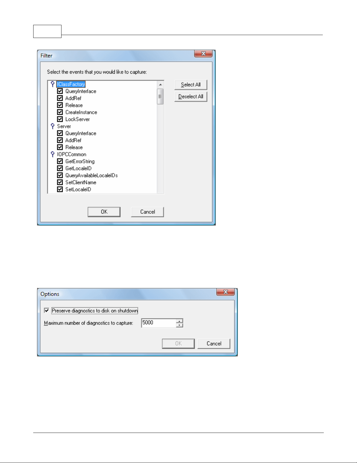
41
KEPServerEX5 Help
Each method (such as, GetErrorString) of every OPC Data Access 1.0, 2.0 and 3.0 interface (such as, IOPCCommon)
supported by the server is available as a filter. Users can select a method by clicking the checkbox to the left of the
method name. Additionally, users can select all methods of an interface by double-clicking the interface name. By
default, all methods for all interfaces are selected.
Note: Filter changes apply only to new events captured. Previous events that meet the filter criteria will not be
removed from the view.
The Options Dialog is used to control certain functionality built into the OPC diagnostics feature.
Remember that the performance of the server is affected by capturing diagnostic information, as it is an additional layer
of processing that occurs between all client/server communications. The OPC diagnostic information is saved to the
installation directory under the file name autosave.opcdiag. The file is only created on shutdown. This functionality is
turned off by default.
Users can also decide whether of not to persist OPC diagnostic information to disk when the server is shutdown by
selecting the Preserve diagnostics to disk on shutdown. This can be useful if users need to go back in time to
determine where a particular issue may have occurred. Users can also create a backup of diagnostics data at any time
through the File | Save As menu option. By default, this functionality is turned on.
www.kepware.com
Page 43

KEPServerEX5 Help
Since diagnostic information affects memory/file storage, users can decide the maximum number of OPC diagnostic
events that should be captured at any specific time by modifying the Maximum number of diagnostics to capture.
This value only pertains to the number of events and does not include the number of details, as the detail count for a
particular event could be potentially very high. The range for this setting is 1000 to 30000. The default value is 5000.
42
OPC Diagnostic Events
Click on a link below to jump to any of the following OPC Diagnostic Events.
IClassFactory
Server
IOPCCommon
IOPCServer
IConnectionPointContainer(Server)
IOPCBrowse
IOPCBrowseServerAddressSpace
IOPCItemProperties
IOPCItemIO
IOPCGroupStateMgt
IOPCGroupStateMgt2
IOPCItemDeadbandMgt
IOPCItemSamplingMgt
IOPCSyncIO
IOPCSyncIO2
IOPCAsyncIO
IDataObject
IAdviseSink
IOPCAsyncIO2
IAsyncIO3
IConnectionPointContainer (Group)
IOPCDataCallback
IEnumOPCItemAttributes
IClassFactory
The IClassFactory interface contains several methods intended to deal with an entire class of objects. It is implemented
on the class object for a specific class of objects and is identified by a CLSID.
QueryInterface - The client can ask the object whether it supports any outgoing interfaces by calling
QueryInterface for IConnectionPointContainer. If the object answers "yes" by handing back a valid pointer, the
client knows it can attempt to establish a connection.
AddRef - Increments the reference count for an interface on an object. It should be called for every new copy of
a pointer to an interface on a given object.
Release - Decreases the reference count of the interface by 1.
CreateInstance - Creates an uninitialized object.
LockServer - Allows instances to be created quickly when called by the client of a class object to keep a server
open in memory.
Server
The client calls CoCreateInstance to create the Server object and the initial interface.
QueryInterface - The client can ask the object whether it supports any outgoing interfaces by calling
QueryInterface for IConnectionPointContainer. If the object answers "yes" by handing back a valid pointer, the
client knows it can attempt to establish a connection.
AddRef - Increments the reference count for an interface on an object. It should be called for every new copy of
a pointer to an interface on a given object.
Release - Decreases the reference count of the interface by 1.
IOPCCommon
This interface is used by all OPC Server types (DataAccess, Alarm&Event, Historical Data and etc.). It provides the
www.kepware.com
Page 44

43
ability to set and query a Locale ID which would be in effect for the particular client/server session. That is, the actions
of one client do not affect other clients.
KEPServerEX5 Help
GetErrorString - Returns the error string for a server specific error code. The expected behavior is that this will
include handling of Win32 errors as well (such as RPC errors).
GetLocale ID - Returns the default Locale ID for this server/client session.
QueryAvailableLocale IDs - Returns the available Locale IDs for this server/client session.
SetClientName - Allows the client to optionally register a client name with the server. This is included primarily
for debugging purposes. The recommended behavior is that users set the Node name and EXE name here.
Set LocalID - Sets the default Locale ID for this server/client session. This Locale ID will be used by the
GetErrorString method on this interface. The default value for the server should be LOCALE_SYSTEM_DEFAULT.
IOPCServer
This is the main interface to an OPC server. The OPC server is registered with the operating system as specified in the
Installation and Registration Chapter of this specification.
AddGroup - Adds a Group to a Server. A Group is a logical container for a client to organize and manipulate data
items.
CreateGroupEnumerator - Creates various enumerators for the groups provided by the Server.
GetErrorString - Returns the error string for a server specific error code.
GetGroupByName - Returns an additional interface pointer when given the name of a private group (created
earlier by the same client). Use GetPublicGroupByName to attach to public groups. This function can be used to
reconnect to a private group for which all interface pointers have been released.
GetStatus - Returns current status information for the server.
RemoveGroup - Deletes the Group. A group is not deleted when all the client interfaces are released, since the
server itself maintains a reference to the group. The client may still call GetGroupByName after all the interfaces
have been released. RemoveGroup() causes the server to release it's 'last' reference to the group, which results
in the group being deleted.
IConnectionPointContainer(Server)
This interface provides the access to the connection point for IOPCShutdown.
EnumConnectionPoints - Creates an enumerator for the connection points supported between the OPC Group
and the Client. OPCServers must return an enumerator that includes IOPCShutdown. Additional vendor specific
callbacks are allowed.
FindConnectionPoints - Finds a particular connection point between the OPC Server and the Client. OPCServers
must support IID_IOPCShutdown. Additional vendor specific callbacks are allowed.
IConnectionPoint(Server) - Establishes a call back to the client.
Advise - Establishes an advisory connection between the connection point and the caller's sink object.
EnumConnections - Creates an enumerator object for iteration through the connections that exist to this
connection point.
GetConnectionInterface - Returns the IID of the outgoing interface managed by this connection point.
UnAdvise - Terminates an advisory connection previously established through the Advise method.
IOPCBrowse
IOPCBrowse interface provides improved methods for browsing the server address space and for obtaining the item
properties.
GetProperties - Returns an array of OPCITEMPROPERTIES, one for each Item ID.
Browse - Browses a single branch of the address space and returns zero or more OPCBROWSEELEMENT
structures.
IOPCBrowseServerAddressSpace
This interface provides a way for clients to browse the available data items in the server, giving the user a list of the
valid definitions for an Item ID. It allows for either flat or hierarchical address spaces and is designed to work well over
a network. It also insulates the client from the syntax of a server vendor specific Item ID.
BrowseAccessPaths - Provides a way to browse the available AccessPaths for an Item ID.
BrowseOPCItem IDs - Returns an IENUMString for a list of Item IDs as determined by the passed parameters.
The position from which the browse is made can be set in ChangeBrowsePosition.
ChangeBroserPosition - Provides a way to move up, down or to in a hierarchical space.
GetItem ID - Provides a way to assemble a fully qualified Item ID in a hierarchical space. This is required since
the browsing functions return only the components or tokens that make up an Item ID and do not return the
delimiters used to separate those tokens. Also, at each point one is browsing just the names below the current
www.kepware.com
Page 45

KEPServerEX5 Help
node (e.g. the units in a cell).
QueryOrganization - Provides a way to determine if the underlying system is inherently flat or hierarchical and
how the server may represent the information of the address space to the client. Flat and hierarchical spaces
behave somewhat different. If the result is flat then the client knows that there is no need to pass the Branch or
Leaf flags to BrowseOPCItem IDs or to call ChangeBrowsePosition.
IOPCItemProperties
This interface can be used to browse the available properties associated with an Item ID as well as to Read the
properties' current values.
GetItemProperties - Returns a list of the current data values for the passed ID codes.
LockUpItem IDs - Returns a list of Item IDs for each of the passed ID codes if any are available. These indicate
the Item ID which could be added to an OPCGroup and used for more efficient access to the data corresponding
to the Item Properties.
QueryAvailableProperties - Returns a list of ID codes and descriptions for the available properties for this Item
ID. This list may differ for different Item IDs. This list is expected to be relatively stable for a particular Item ID,
although it could be affected from time to time by changes to the underlying system's configuration. The Item ID
is passed to this function because servers are allowed to return different sets of properties for different Item IDs.
IOPCItemIO
The purpose of this interface is to provide an extremely easy way for simple applications to obtain OPC data.
Read - Reads one or more values, qualities and timestamps for the items specified. This is functionally similar to
the IOPCSyncIO::Read method.
WriteVQT - Writes one or more values, qualities and timestamps for the items specified. This is functionally
similar to the IOPCSyncIO2::WriteVQT except that there is no associated group. If a client attempts to write VQ,
VT, or VQT it should expect that the server will Write them all or none at all.
Group - The client calls CoCreateInstance to create the Server object and the initial interface.
QueryItnerface - The client can ask the object whether it supports any outgoing interfaces by calling
QueryInterface for IConnectionPointContainer. If the object answers "yes" by handing back a valid pointer, the
client knows it can attempt to establish a connection.
AddRef - Increments the reference count for an interface on an object. It should be called for every new copy of
a pointer to an interface on a given object.
Release - Decreases the reference count of the interface by 1.
IOPCGroupStateMgt
IOPCGroupStateMgt allows the client to manage the overall state of the group. Primarily, this accounts for changes
made to the group's update rate and active state.
CloneGroup - Creates a second copy of a group with a unique name.
GetState - Gets the current state of the group. This function is typically called to obtain the current values of
this information prior to calling SetState. This information was all supplied by or returned to the client when the
group was created.
SetName - Changes the name of a private group. The name must be unique. The name cannot be changed for
public groups. Group names are required to be unique with respect to an individual client to server connection.
SetState - Sets various properties of the group. This represents a new group which is independent of the
original group.
IOPCGroupStateMgt2
This interface was added to enhance the existing IOPCGroupStateMgt interface.
SetKeepAlive - Causes the server to provide client callbacks on the subscription when there are no new events
to report. Clients can then be assured of the health of the server and subscription without resorting to pinging
the server with calls to GetStatus().
GetKeepAlive - Returns the currently active keep-alive time for the subscription.
IOPCItemMgt - IOPCItemMgt allows a client to add, remove and control the behavior of items is a group.
AddItems - Adds one or more items to a group. It is acceptable to add the same item to the group more than
once, thus generating a second item with a unique ServerHandle.
CreateEnumerator - Creates an enumerator for the items in the group.
RemoveItems - Removes items from a group. Removing items from a group does not affect the address space
of the server or physical Device. It simply indicates whether or not the client is interested in those particular
items.
SetactiveState - Sets one or more items in a group to active or inactive. This controls whether or not valid data
44
www.kepware.com
Page 46

45
KEPServerEX5 Help
can be obtained from Read cache for those items and whether or not they are included in the IAdvise
subscription to the group. Deactivating items will not result in a callback, since by definition callbacks do not
occur for inactive items. Activating items will generally result in an IAdvise callback at the next UpdateRate
period.
SetClientHandles - Changes the client handle for one or more items in a group. In general, it is expected that
clients will set the client handle when the item is added and not change it later.
SetDataTypes - Changes the requested data type for one or more items in a group. In general, it is expected
that clients will set the requested datatype when the item is added and not change it later.
ValidateItems - Determines if an item is valid and could be added without error. It also returns information
about the item such as canonical datatype. It does not affect the group in any way.
IOPCItemDeadbandMgt
Force a callback to IOPCDataCallback::OnDataChange for all active items in the group, whether they have changed or
not. Inactive items are not included in the callback. The MaxAge value will determine where the data is obtained. There
will be only one MaxAge value, which will determine the MaxAge for all active items in the group. This means some of
the values may be obtained from cache while others could be obtained from the Device depending on the "freshness" of
the data in the cache.
SetItemDeadband - Overrides the deadband specified for the group for each item.
GetItemDeadband - Gets the deadband values for each of the requested items.
ClearItemDeadband - Clears the individual item PercentDeadband, effectively reverting them back to the
deadband value set in the group.
IOPCItemSamplingMgt
This optional interface allows the client to manipulate the rate at which individual items within a group are obtained
from the underlying Device. It does not affect the group update rate of the callbacks for OnDataChange.
SetItemSamplingRate - Sets the sampling rate on individual items. This overrides the update rate of the group
as far as collection from the underlying Device is concerned. The update rate associated with individual items
does not affect the callback period.
GetItemSamplingRate - Gets the sampling rate on individual items, which was previously set with
SetItemSamplingRate.
ClearItemSamplngRate - Clears the sampling rate on individual items, which was previously set with
SetItemSamplingRate. The item will revert back to the update rate of the group.
SetItemBufferEnable - Requests that the server turns on or off, depending on the value of the bEnable
parameter, the buffering of data for the identified items, which are collected for items that have an update rate
faster than the group update rate.
GetItemBufferEnable - Queries the current state of the servers buffering for requested items.
IOPCSyncIO
IOPCSyncIO allows a client to perform synchronous Read and Write operations to a server. The operations will run to
completion.
Read - Reads the value, quality and timestamp information for one or more items in a group. The function runs
to completion before returning. The data can be read from cache in which case it should be accurate to within the
'UpdateRate' and percent deadband of the group. The data can be read from the Device, in which case an actual
Read of the physical Device must be performed. The exact implementation of cache and Device Reads is not
defined by the specification.
Write- Writes values to one or more items in a group. The function runs to completion. The values are written to
the Device, meaning that the function should not return until it verifies that the Device has actually accepted or
rejected the data. Writes are not affected by the active state of the group or item.
IOPCSyncIO2
This interface was added to enhance the existing IOPCSyncIO interface.
ReadMaxAge - Reads one or more values, qualities and timestamps for the items specified. This is functionally
similar to the OPCSyncIO::Read method except no source is specified (Device or cache). The server will make
the determination as whether the information will be obtained from the Device or cache. This decision will be
based upon the MaxAge parameter. If the information in the cache is within the MaxAge, then the data will be
obtained from the cache, otherwise the server must access the Device for the requested information.
WriteVQT - Writes one or more values, qualities and timestamps for the items specified. This is functionally
similar to the IOPCSyncIO::Write except that Quality and Timestamp may be written. If a client attempts to write
VQ, VT or VQT it should expect that the server will Write to all or none.
IOPCAsyncIO
IOPCAsyncIO allows a client to perform asynchronous Read and Write operations to a server. The operations will be
www.kepware.com
Page 47

KEPServerEX5 Help
'queued' and the function will return immediately so that the client can continue to run. Each operation is treated as a
'transaction' and is associated with a Transaction ID. As the operations are completed, a callback will be made to the
IAdvise Sink in the client (if one has been established). The information in the callback will indicate the Transaction ID
and the error results. By convention, 0 is an invalid Transaction ID.
Cancel - Requests that the server cancel an outstanding transaction.
Read - Reads one or more items in a group. The results are returned via the IAdvise Sink connection established
through the IDataObject. For cache Reads the data is only valid if both the group and the item are active. Device
Reads are not affected by the active state of the group or item.
Refresh - Forces a callback for all active items in the group, whether they have changed or not. Inactive items
are not included in the callback.
Write - Writes one or more items in a group. The results are returned via the IAdviseSink connection established
through the IDataObject.
46
IDataObject
IDataObject is implemented on the OPCGroup rather than on the individual items. This allows the creation of an Advise
connection between the client and the group using the OPC Data Stream Formats for the efficient data transfer.
DAdvise - Create a connection for a particular 'stream' format between the OPC Group and the Client.
DUnadvise - Terminate a connection between the OPC Group and the Client.
IAdviseSink
The client only has to provide a full implementation of OnDataChange.
OnDataChange - This method is provided by the client to handle notifications from the OPC Group for exception
based data changes, Async Reads and Refreshes and Async Write Complete.
IOPCAsyncIO2
This interface is similar to IOPCAsync(OPC 1.0) and is intended to replace IOPCAsyncIO. It was added in OPC 2.05.
Cancel2 - Requests that the server cancel an outstanding transaction.
GetEnable - Retrieves the last Callback Enable value set with SetEnable.
Read - Reads one or more items in a group. The results are returned via the client's IOPCDataCallback
connection established through the server's IConnectionPointContainer. Reads are from 'Device' and are not
affected by the active state of the group or item.
Refresh2 - Forces a callback to IOPCDataCallback::OnDataChange for all active items in the group, whether they
have changed or not. Inactive items are not included in the callback.
SetEnable - Controls the operation of OnDataChange. Setting Enable to False will disable any OnDataChange
callbacks with a transaction ID of 0 (which are not the result of a Refresh). The initial value of this variable when
the group is created is True; thus, OnDataChange callbacks are enabled by default.
Write - Writes one or more items in a group. The results are returned via the client's IOPCDataCallback
connection established through the server's IConnectionPointContainer.
IAsyncIO3
This interface was added to enhance the existing IOPCAsyncIO2 interface.
ReadMaxAge - Reads one or more values, qualities and timestamps for the items specified. This is functionally
similar to the OPCSyncIO::Read method except it is asynchronous and no source is specified (Device or cache).
The server will make the determination as whether the information will be obtained from the Device or cache.
This decision will be based upon the MaxAge parameter. If the information in the cache is within the MaxAge,
then the data will be obtained from the cache; otherwise, the server must access the Device for the requested
information.
WriteVQT - Writes one or more values, qualities and timestamps for the items specified. The results are
returned via the client's IOPCDataCallback connection established through the server's
IConnectionPointContainer. This is functionally similar to the IOPCAsyncIO2::Write except that Quality and
Timestamp may be written. If a client attempts to write VQ, VT or VQT it should expect that the server will Write
them all or none at all.
RefreshMaxAge - Forces a callback to IOPCDataCallback::OnDataChange for all active items in the group,
whether or not they have changed. Inactive items are not included in the callback. The MaxAge value determines
where the data is obtained. There will be only one MaxAge value, which determines the MaxAge for all active
items in the group. This means some of the values may be obtained from cache while others can be obtained
from the Device, depending on the type of the data in the cache.
IConnectionPointContainer (Group)
This interface provides functionality similar to the IDataObject but is easier to implement and to understand. It also
provides the functionality missing from the IDataObject Interface. The client must use the new IOPCAsyncIO2 interface
to communicate via connections established with this interface. The 'old' IOPCAsnyc will continue to communicate via
www.kepware.com
Page 48

47
IDataObject connections as in the past.
KEPServerEX5 Help
EnumConnectionPoints - Creates an enumerator for the Connection Points supported between the OPC Group
and the Client.
FindConnectionPoint - Finds a particular connection point between the OPC Group and the Client.
IconnectionPoint (Group) - Establishes a call back to the client.
Advise - Establishes an advisory connection between the connection point and the caller's sink object.
EnumConnections - Creates an enumerator object for iteration through the connections that exist to this
connection point.
GetConnectionInterface - Returns the IID of the outgoing interface managed by this connection point.
GetConnectionPointContainer - Retrieves the IConnectionPointContainer interface pointer to the connectable
object that conceptually owns the connection point.
Unadvise - Terminates an advisory connection previously established through the Advise method.
IOPCDataCallback
In order to use connection points, the client must create an object that supports both the IUnknown and
IOPCDataCallback Interface.
OnDataChange - This method is provided by the client to handle notifications from the OPC Group for exception
based data changes and Refreshes.
OnReadComplete - This method is provided by the client to handle notifications from the OPC Group on
completion of Async Reads.
OnWriteComplete - This method is provided by the client to handle notifications from the OPC Group on
completion of AsyncIO2 Writes.
OnCancelComplete - This method is provided by the client to handle notifications from the OPC Group on
completion of Async Cancel.
IEnumOPCItemAttributes
IEnumOPCItemAttributes allows clients to find out the contents of a group and the attributes of those items. Most of the
returned information is either supplied by or returned to the client at the time it called AddItem.
Clone - Creates a second copy of the enumerator. The new enumerator is initially in the same state as the
current enumerator.
Next - Fetches the next 'celt' items from the group.
Reset - Resets the enumerator back to the first item.
Skip - Skips over the next 'celt' attributes.
Important: For more information on the general principles of Connection points, refer to Microsoft documentation.
Channel Diagnostics
The server's diagnostic features provides real-time data on the communication driver's performance. All Read and Write
operations can either be viewed in the diagnostic display window or tracked directly in the OPC client application by
using built-in Diagnostics Tags. These diagnostics make it easy to debug communication issues. The diagnostic
display window also provides a real-time protocol view, which is useful when making changes to key communication
parameter settings (such as baud rate, parity or Device IDs). The changes' effects are displayed in real-time. Once the
correct communication and device settings are set, users will immediately see the exchange of data with the device.
To modify the operation of the Diagnostic Window, right-click in the window's protocol view.
www.kepware.com
Page 49
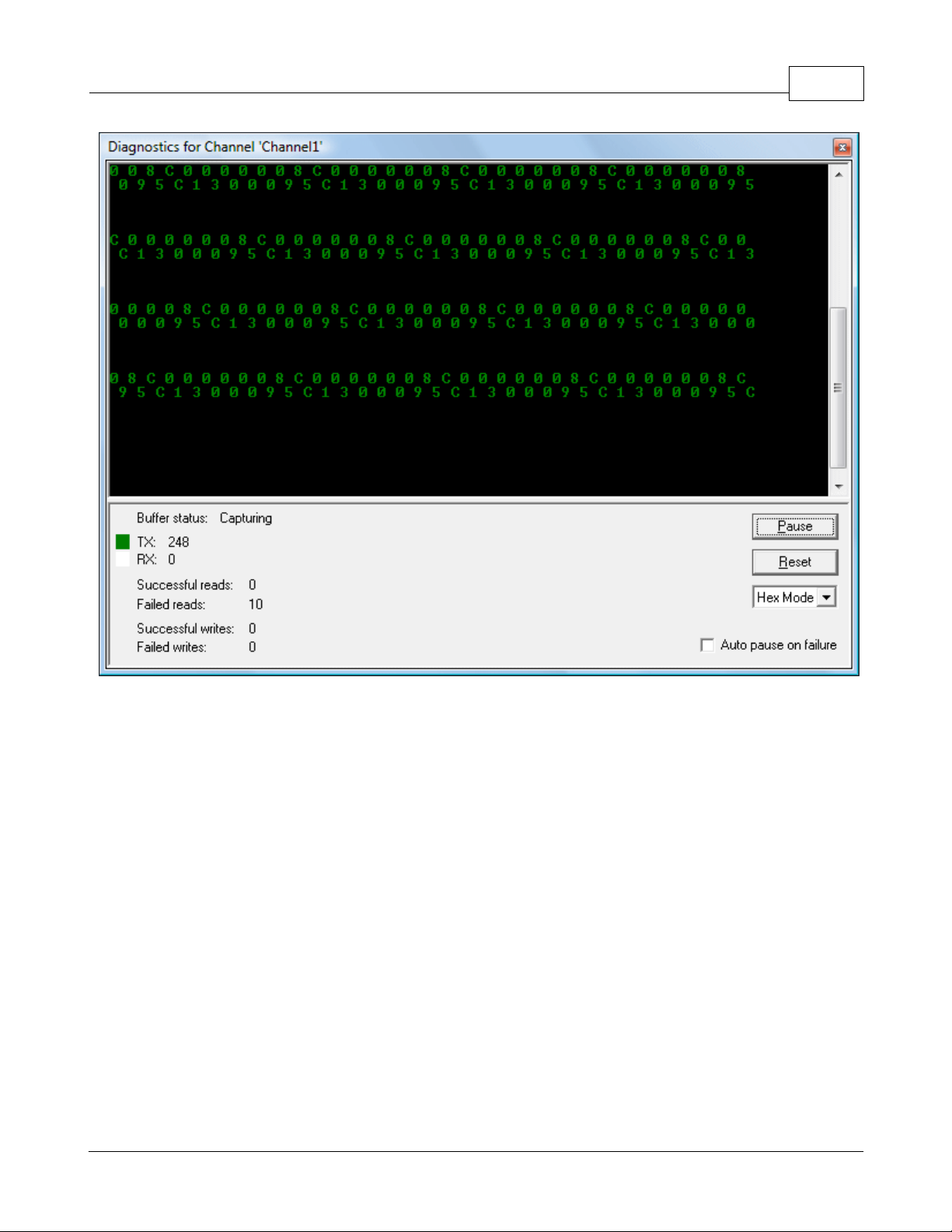
KEPServerEX5 Help
48
Note: The Diagnostic Window operates in a modeless form that allows it to exist while other dialogs in the server are
open.
Diagnostic Controls
Descriptions of the Diagnostics Controls are as follows.
Pause captures and freezes the protocol data in the Diagnostics Window. The Diagnostics Tags will continue to
be updated.
Reset clears only the contents of the protocol view and does not affect the Diagnostics Tags.
Mode displays the protocol information in a pure Hex representation (Hex Mode) or in a mixture of ASCII and
Hex representation (Mix Mode). Depending on the target device's nature, the Mode selection may need to be
changed to provide the best view of the protocol.
Auto Pause on failure function causes the capture buffer of the protocol view to stop whenever either a Read or
Write error occurs. This selection is turned off by default and the protocol capture will run in continuous mode.
Auto Pause is a great way to capture intermittent communications issues.
Using the Diagnostic Window
Before attempting to use the Diagnostic Window, ensure that diagnostic functions have been enabled in Channel
Properties. Next, display the Diagnostic Window by either selecting it from a context menu on the channel or by
clicking View | Diagnostics. Once the diagnostic menu is displayed, it will begin capturing the real-time protocol data.
If communications are occurring properly, there will be a stream of communications messages between the server and
the device. Users can tell when this is occurring due to both the two-color scheme of the protocol window and by the
current counts of the Diagnostics Tags.
If, for some reason, communications do not appear to be occurring normally, the channel's parameters can be accessed
easily. The diagnostic window will remain displayed even when users display the Channel Properties for settings like the
communications parameters. This allows users to interactively change communications parameters while monitoring the
www.kepware.com
Page 50

49
effect in the protocol view. Remember to display the diagnostic window before accessing any parameter dialogs.
Once the diagnostic window is displayed, various communication and device settings in the channel and device can be
modified to see the effect on the communications stream. If a communications problem persists, right-click in the
diagnostic window to invoke the context menu. The selections available from this menu can be used to tailor the
operation of the diagnostic window and copy the contents of the protocol view to the Clipboard.
Descriptions are as follows.
KEPServerEX5 Help
Copy to Clipboard helps Technical Support solve many communications issues when they occur. This selection
formats the protocol capture buffer's contents as text for easy "cut and paste" into either an email or fax
message (which can then be sent to Technical Support for analysis and diagnosis).
Save as Text File saves the current contents of the protocol view directly to a text file.
Auto Scroll ensures that the protocol view will automatically scroll to the next line as new protocol data is
received.
Always on Top forces the Diagnostics Window to remain on the top of all other application windows. This is the
default condition.
Options… is used to select a buffer size for the protocol capture buffer, set the font and size used by the
protocol view and also assign unique colors to both the transmit and receive data streams.
Buffer Size is used to select a capture buffer of 1024, 2048, 4096, 8192, 16384, 32768 or 65536 bytes. Depending on
the device's speed, a larger buffer size may be needed to effectively capture protocol related issues.
Display is used to tailor the appearance of the protocol view. The Background, TX Characters and RX Characters color
selections can be used to select from a palette of 16 available colors. Each selection is required to be unique. The font
used by the protocol view can also be selected from this dialog, as well as the size of that font. When selecting a font,
www.kepware.com
Page 51

KEPServerEX5 Help
keep in mind that it can affect the speed of update if the size is set to large. Larger font sizes also prevent users from
being able to see a usable amount of the protocol.
50
Basic Server Components
For more information on a specific server component, select a link from the list below.
What is a Channel?
What is a Device?
What is a Tag?
What is a Tag Group?
What is the Alias Map?
What is a Channel?
Channel Functions
A channel represents a communication medium from the PC to one or more external devices. A channel can be used to
represent a serial port, a card installed in the PC or an Ethernet socket.
Before adding devices to a project, users must define the channel that will be used when communicating with devices. A
channel and a device driver are closely tied. After creating a channel, only devices that the selected driver supports can
be added to this channel.
Adding a Channel
Channels are added using the Channel Wizard, which guide users through the channel definition process. To start,
users will be prompted for a logical name to assign the channel. This name must be unique among all channels and
devices defined in the project. Next, users will be prompted for the device driver that will be used. A list box is
presented that displays all of the device drivers currently installed in the system. All serial drivers can be used with
multiple channels in the same project.
Note: For hardware card drivers, refer to the driver's help documentation the determine the ability to use with multiple
channels in a single project. For information on how to determine the number of supported channels, refer to Server
Summary Information.
Users will then be prompted for the specific communication parameters to be used. Multiple channels cannot share
www.kepware.com
Page 52

51
identical communication parameters; for example, two serial drivers cannot use COM1. For the correct communication
parameters of a particular device, refer to both the manufacturer's and the driver's help documentation.
Note: Flow Control settings for serial drivers are primarily used when connecting RS422/485 network devices to the
RS232 serial port via a converter. Most RS232 to RS422/485 converters require either no flow control (None) or that
the RTS line be on when the PC is transmitting and off when listening (RTS).
The Channel Wizard will finish with a summary of the new channel.
KEPServerEX5 Help
Removing a Channel
To remove a channel from the project, select the desired channel and then press the Delete key. Alternatively, select
Edit | Delete from the Edit menu or toolbar.
Displaying Channel Properties
To display the Channel Properties of a specific channel, select the channel and then click Edit | Properties from the
Edit menu or toolbar.
See Also: Channel Properties
Channel Properties - General
Each protocol or driver used in a server project is called a channel, which refers to a specific communications driver. A
server project can consist of many channels: each with unique communications drivers or each with the same
communications driver.
In a server application, every channel name must be unique. Although names can be up to 256 characters long, some
OPC client applications may have a limited display window when browsing the tag space of an OPC server. The channel
name entered will be part of the OPC browser information.
Checking the Enable diagnostics check box will make the channel's diagnostic information available to the OPC
application. With diagnostic functions enabled, Diagnostic Tags and the OPC Diagnostic Window can be used within
client applications. Because the diagnostic features of the server require a minimal amount of overhead processing, it is
recommended that users only utilize the diagnostic features when needed and disable them when not in use. This is the
default condition.
www.kepware.com
Page 53

KEPServerEX5 Help
Note: With the server's online full-time operation, these parameters can be changed at any time. This includes
changing the channel name in order to prevent clients from registering data with the server. If a client has already
acquired an item from the server before the channel name is changed, the items will be unaffected. If, after the channel
name has been changed, the client application releases the item and attempts to re-acquire using the old channel
name, the item will not be accepted. With this in mind, changes to the parameters should not be made once a large
client application has been developed. Utilize the User Manager to prevent operators from changing parameters and
restrict access rights to server features.
52
Channel Properties - Communication Parameters
The dialog seen under this heading will vary depending on the device driver that has been selected. If a serial device
driver has been selected, a dialog should appear similar to the following.
Users will be asked to provide the following information.
ID specifies the Communications ID that will be used when communicating with devices assigned to the channel.
Baud Rate specifies the baud rate that should be used to configure the selected Communications port.
Data Bits specifies the number of data bits per data word (5, 6, 7, or 8).
Parity specifies the type of parity the data should use (Odd, Even, or None).
Stop Bits specifies the number of stop bits per data word (1 or 2).
Flow Control determines how the RTS and DTR control lines should be utilized.
Use Modem: If planning to use a modem to communicate with devices connected to the port, check this box.
This selection is only available if a modem has been defined for the PC.
If Use Modem has been selected, the next page allows users to select a unique modem to use for each channel.
After selecting a modem, users can set the dialing and modem properties for the channel. Dialing properties
allow users to specify where the call is coming from and how the server should dial an outside line or long
distance number. For these settings to take effect, the phone number must be in canonical format. Use the
Properties dialog to configure the modem, and refer to the modem's documentation for assistance. See Also:
Using a Modem in the Server Project.
www.kepware.com
Page 54

53
Note: With the server's online full-time operation, these parameters can be changed at any time (including
communications port, baud rate and etc.). Utilize the User Manager to restrict access rights to server features and
prevent operators from changing the parameters. Changes made to these parameters can temporarily disrupt
communications.
KEPServerEX5 Help
Report Comm. Errors turns the reporting of low level communications errors On or Off. When enabled, lowlevel errors (such as parity, framing and overrun errors) are posted to the event log when they occur. When
disabled, these same errors will not be posted even though normal request failures will be.
Use Ethernet Encapsulation: Many serial drivers also support Ethernet Encapsulation mode, which uses an
Ethernet based serial port gateway instead of the normal PC based serial port. See Also: Channel Properties -
Ethernet Encapsulation.
Flow Control RTS & DTS
Flow control may be required in order to communicate with a specific serial device. Descriptions of the available flow
control options are as follows.
None: No control lines are toggled or asserted.
DTR: The DTR line is asserted when the communications port is opened and remains on.
RTS: This specifies that the RTS line will be high if bytes are available for transmission. After all buffered bytes
have been sent, the RTS line will be low. This is normally used with RS232/RS485 converter hardware.
RTS, DTR: This is a combination of DTR and RTS as described above.
RTS Always: The RTS line is asserted when the communication port is opened and remains on.
RTS Manual: The RTS line is asserted based upon the timing parameters entered for manual RTS control.
Channel Properties - Network Interface
With the addition of Ethernet Encapsulation, virtually all of the drivers currently available support some form of Ethernet
communications. Whether a natively Ethernet based driver or a serial driver configured for Ethernet Encapsulation is
being used, some form of a network interface will be used. In most cases, that interface takes the form of a Network
Interface Card (NIC). For a PC that has networking installed, this usually means that a single NIC is installed that
provides a connection to either the IT or plant floor network (or both). This configuration normally works very well for
typical network configurations and loading. While this configuration might be fine for normal performance levels,
problems may arise if data needs to be received from an Ethernet device at a regular interval. If the plant floor network
is mixed with the IT network, a large batch file transfer could completely disrupt the interval of the plant floor data.
The most common way to deal with this issue is to install a second NIC in the PC. Then, one NIC can be used for
accessing the IT network while the other NIC accesses the plant floor data. Although this may sound reasonable, simple
problems occur when trying to separate the networks. When using multiple NICs, users must determine the bind order
. The bind order determines what NIC is used to access different portions of the Ethernet network. In many cases, bind
settings can be easily managed using the operating system's tools.
When there is a clear separation between the types of protocols and services that will be used on each NIC card, the
bind order can be created by the operating system. If there isn't a clear way to select a specific bind order, users may
find that the Ethernet device connection is being routed to the wrong network. In this case, the Network Interface
shown below can be used to select a specific NIC card to use with the Ethernet driver. The Network Interface selection
can be used to select a specific NIC card based on either the NIC name or its currently assigned IP address. This list of
available NICs will include either unique NIC cards or NICs that have multiple IP assigned to them. The selection will
also display any WAN connections are active (such as a dialup connection).
www.kepware.com
Page 55

KEPServerEX5 Help
54
By selecting a specific NIC interface, users will be able to force the driver to send all Ethernet communication through
the specified NIC. When a NIC is selected, the normal operating system bind order is completely bypassed. This
ensures that users have control over how the network operates and thus eliminates any guesswork.
The selections shown in the Network Adapter drop-down menu depend on three things: the network configuration
settings, the number of unique NICs installed in the PC and the number of unique IPs assigned to the NICs. In order to
force the operating system to create the bind order selection, select Default as the network adapter. This allows the
driver to use the operating system's normal bind order to set the NIC that will be used.
Important: Always select the Default condition if unsure of which NIC to use. Similarly, the Default condition is
recommended if an Ethernet based device is being used and this feature is exposed through a product upgrade.
Note: With the server's online full-time operation, these parameters can be changed at any time. Utilize the User
Manager to restrict access rights to server features and prevent operators from changing the parameters. Keep in mind
that changes made to this parameter can temporarily disrupt communications.
Channel Properties - Manual RTS Flow Control
The Flow Control selection of RTS Manual allows the server to control the operation of the RTS line for use with external
devices (such as radio modems) that require additional timing to properly initiate communications.
www.kepware.com
Page 56

55
KEPServerEX5 Help
For those drivers that support it, the RTS Manual selection enables the setting of three timing parameters. These
settings will only appear if the driver in use supports RTS Manual.
Raise the RTS line controls how long the RTS line will be high before any data is transmitted from the
communications port. The time entered is in milliseconds and has a valid range of 0 to 2550 milliseconds. The
default is 10 milliseconds.
Drop the RTS line controls how long the RTS line will be held high after any data is transmitted from the
communications port. The time entered is in milliseconds and has a valid range of 0 to 2550 milliseconds. The
default is 10 milliseconds.
Poll Delay allows a delay to be introduced between each communication request. Some radio modems need a
defined amount of settling time before the next transmission can occur. The Poll Delay is used to configure that
delay. The time entered is in milliseconds and has a valid range of 0 to 2550 milliseconds. The default is 10
milliseconds.
Note: With the server's online full-time operation, these parameters can be changed at any time. Utilize the User
Manager to restrict access rights to specific server features in order to prevent operators from changing the
parameters.
Channel Properties - Modem
If Modem Support has been selected for the application, users must select the modem they intend to use for the
channel. The Channel Properties - Modem dialog is used to select a modem from the list that are configured for the PC,
set its properties and enter Phonebook Tags. Once the modem has been selected, its settings must be configured to
match that of the target device. For more information on Modem Configuration , refer to Using a Modem in the
Server Project.
Once the modem has been properly configured, users can begin using modem tags directly in their application to set
the desired phone number to dial. Users can also establish a list of phone numbers that can be seen as OPC tags from
the OPC client application. The Phonebook Tags, once configured, can be used to automatically dial a desired number
simply by writing anything to the tag. To enter a Phonebook Tag, click on the Phonebook button.
www.kepware.com
Page 57

KEPServerEX5 Help
56
Note: With the server's online full-time operation, these parameters can be changed at any time. Utilize the User
Manager to restrict access rights to server features and prevent operators from changing parameters.
Channel Properties - Write Optimizations
As with any OPC server, writing data to the device may be the application's most important aspect. The server's
objective is to ensure that the data written from the OPC client application gets to the device in a timely fashion. Given
this goal, the server provides a number of optimization settings that can be used to tailor the server to meet specific
needs and improve the application's responsiveness.
Optimization Method
The Write Optimization dialog is mainly used to control how Write data is passed to the underlying communications
driver as well as to adjust the ratio at which those Writes will be processed and then sent to the device.
www.kepware.com
Page 58

57
KEPServerEX5 Help
1. Write all values for all tags
'Write all values for all tags' forces the server to attempt to Write every value to the controller. In this mode, the server
continues to gather OPC Write requests and add them to the server's internal Write queue. Then, the server processes
the Write queue and attempts to empty it by writing data to the device as quickly as possible. This mode ensures that
everything written from the OPC client applications will be sent to the target device. This mode should be selected if the
Write operations's order or the Write item's content must uniquely be seen at the target device. This is the default
mode.
2. Write only latest value for non-Boolean tags
Many consecutive Writes to the same value can accumulate in the Write queue, due to the time required to actually
send the data to the device. If the server were to update a Write value that has already been placed in the Write queue,
far fewer Writes would need to be done to reach the same final output value. In this way, no extra Writes accumulate in
the server's queue. When the user stops moving the slide switch, the value in the device is at the correct value at
virtually the same time. This is the mode of operation that the second Write optimization mode, 'Write only latest value
for non-Boolean tags,' allows. As the mode states, any value that is not a Boolean value will be updated in the server's
internal Write queue and will then be sent to the device at the next possible opportunity. This can greatly improve the
application's overall performance.
Note: 'Write only latest value for non-Boolean tags' does not attempt to optimize Writes to Boolean values. This allows
users to optimize the operation of HMI data (such as the slide switch example) without causing problems with Boolean
operations like a momentary push button.
3. Write only the latest value for all tags
'Write only the latest value for all tags' takes the theory behind the second optimization mode and applies it to all tags.
It is especially useful if the application only needs to send the latest value to the device. This mode optimizes all Writes
by updating the tags currently in the Write queue before they are sent.
Duty Cycle
The Duty Cycle selection is used to control the ratio of Write operations to Read operations. The ratio is always based
on one Read for every one to ten Writes. The duty cycle is set to ten by default, meaning that ten Writes will occur for
each Read operation. Although the application is doing a large number of continuous Writes, it must be ensured that
Read data is still given time to process. A setting of one will result in one Read operation for every Write operation. If
there are no Write operations to perform, Reads will be processed continuously.
Note: We strongly suggest that the application be characterized for compatibility with these Write optimization
www.kepware.com
Page 59

KEPServerEX5 Help
enhancements before they are used in a production environment.
58
Channel Properties - Ethernet Encapsulation
Ethernet Encapsulation mode has been designed to provide communication with serial devices connected to terminal
servers on the Ethernet network. A terminal server is essentially a virtual serial port. The terminal server converts TCP/
IP messages on the Ethernet network to serial data. Once the message has been converted to a serial form, users can
connect standard devices that support serial communications to the terminal server. For more information, refer to
How Do I.. .
Ethernet Encapsulation can be used over wireless network connections (such as 802.11b and CDPD packet networks)
and has also been developed to support a wide range of serial devices. Using a terminal server device allows users to
place RS-232 and RS-485 devices throughout the plant operations while still allowing a single localized PC to access the
remotely mounted devices. Ethernet Encapsulation also allows an individual Network IP address to be assigned to
device as needed. By using multiple terminal servers, users can access hundreds of serial devices from a single PC.
Configuring Ethernet Encapsulation Mode
To use Ethernet Encapsulation, click the Use Ethernet Encapsulation checkbox in Communications Parameters
while in the Channel Wizard. Alternatively, click Channel Properties | Communications as shown below.
Important: When Ethernet Encapsulation mode is selected, the serial port settings (such as baud rate, data bits and
parity) will become greyed out. This occurs because these settings cannot be used in Ethernet Encapsulation mode. The
terminal server being used must, however, have its serial port properly configured to match the requirements of the
serial device that will be attached to the terminal server.
The server's multiple channel support allows users to have up to 16 channels on each driver protocol. When using
multiple channels, a channel can be defined to use the local PC serial port and another channel can be defined to use
Ethernet Encapsulation mode.
Channel-level Ethernet Encapsulation Settings
Once Ethernet Encapsulation mode has been enabled, users need to configure its settings. If Use Ethernet
Encapsulation was checked in the Communications Parameters dialog of the wizard, the settings will be displayed in a
Channel Wizard dialog. To access the settings after the channel has been added, right-click on the channel and then
select Properties | Ethernet Encapsulation.
www.kepware.com
Page 60
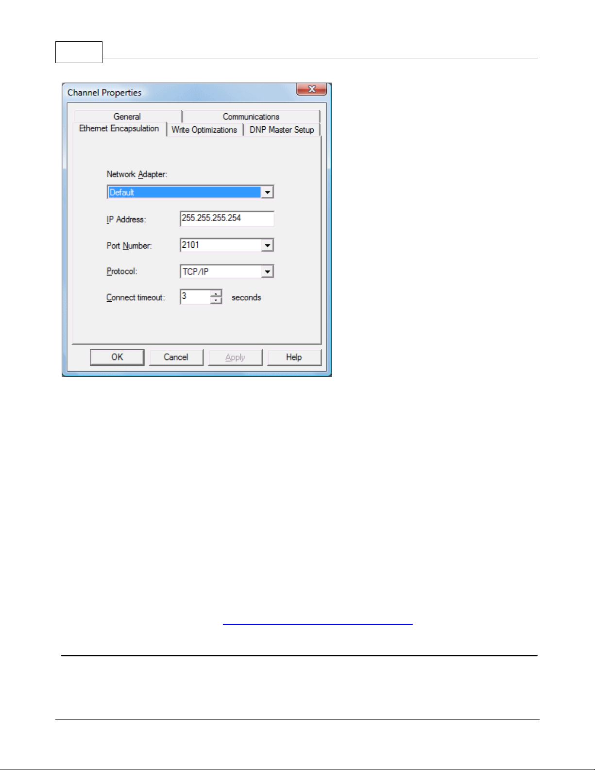
59
KEPServerEX5 Help
The Network Adapter parameter's drop-down list is used to select the network adapter.
The IP Address parameter is used to enter the four-field IP address of the terminal server to which this device
is attached. IPs are specified as YYY.YYY.YYY.YYY The YYY designates the IP address: each YYY byte should be in
the range of 0 to 255. Each channel will have its own IP address.
The Port Number parameter is used to configure the Ethernet port that will be used when connecting to a
remote terminal server. The valid range is from 1 to 65535, with some numbers reserved. The default is 2101.
The Protocol parameter is used to select either TCP/IP or UDP communications and depends entirely on the
nature of the terminal server being used. The default protocol selection is TCP/IP. For more information on the
protocol available, refer to the terminal server's help documentation.
Important: The Ethernet Encapsulation mode is completely transparent to the actual serial communications
driver. With this in mind, users must configure the remaining device settings just as if they were connecting to
the device directly on the local PC serial port.
The Connect Timeout setting defines the amount of time in seconds that is required to establish a socket
connection for a remote device to be adjusted. In many cases, the connection time to a device can take longer
than a normal communications request to that same device. The valid range is 1 to 999 seconds. The default is 3
seconds.
Note: With the server's online full-time operation, these parameters can be changed at any time. Utilize the User
Manager to restrict access rights to server features and prevent operators from changing the parameters.
Cable Diagrams
For more information on cables, refer to How To... Select the Correct Network Cable.
What is a Device?
Device Functions
Devices represent the PLCs or other hardware with which the server communicates. The device driver that the channel
is using restricts device selection.
www.kepware.com
Page 61
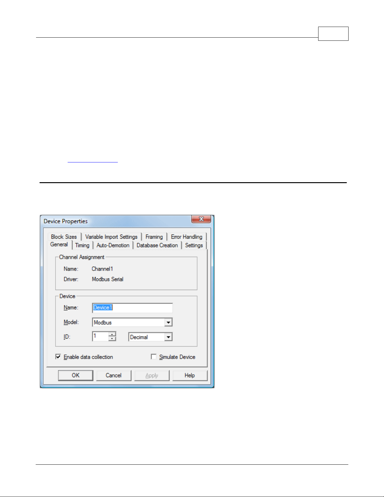
KEPServerEX5 Help
60
Adding a Device
Devices can be added using the New Device Wizard both at the initial setup and afterwards. To do so, click Edit | New
Device. Users will be prompted to enter the Device Name, which is user-defined and should be logical for the device.
This will be the browser branch name used in OPC links to access the device's assigned tags. Users will also be
prompted to enter a Network ID, which is a number or string that uniquely identifies the device on the device's
network. Networked, multi-dropped devices must have a unique identifier so that the server's data requests are routed
correctly. Devices that are not multi-dropped do not need an ID; thus, this setting is not available.
Removing a Device
To remove a device from the project, select the desired device then press Delete. Alternatively, select Edit | Delete
from the Edit menu or toolbar.
Displaying Device Properties
In order to display a device's properties, first select the device and then click Edit | Properties from the Edit menu or
toolbar.
See Also: Device Properties
Device Properties - General
There are a couple of steps required before a project can be configured. First, a channel must be created. Next, a
device, which represents a single target on a communications channel, must be added to that channel. If the chosen
driver supports multiple controllers, a Device ID must then be created for each controller. The following images
demonstrate the appearance of general Serial and Ethernet Device Properties dialogs.
Figure 1 - Serial Device Properties
www.kepware.com
Page 62

61
KEPServerEX5 Help
Figure 2 - Ethernet Device Properties
Device Names
Device Names, which are logical user-defined names for the device, can be up to 256 characters long. The same names
can be used on multiple channels. While long descriptive names are generally a good idea, some OPC client applications
may have a limited display window when browsing the tag space of an OPC server. The device name and channel name
will become part of the browse tree information as well.
Within an OPC client, the combination of channel name and device name would appear as "ChannelName.DeviceName".
Model
Model is used to select the specific type of the device associated with this ID. The model selection's drop-down menu
contents will vary depending on the communications driver. If a driver does not support a specific model, the model will
be greyed out. If the communication driver being used supports multiple models, try to match the model selection to
the physical device. If the device being used is not represented in the model drop down, select a model that conforms
closest to the target device. To determine this, refer to the driver help documentation that discusses each available
model. In some drivers, a model selection called Open is available, which allows users to communicate without knowing
the specific details of the target device.
Device ID
The Device ID is used to specify a device's driver specific station or node. The type of ID entered will depend on the
communications driver being used. For many communication drivers, the ID is a numeric value. As shown in Figure 1
above, when a driver supports a numeric ID, the menu option allows users to enter a numeric value. Additionally, the
format of the numeric value can be changed to suit the needs of either the application or the characteristics of the
chosen communication driver. The format is set by the driver by default. Possible formats include Decimal, Octal and
Hexadecimal.
If the driver in use is either Ethernet-based or happens to support an unconventional station or node name, Figure 2
may be shown. In this case, the Device ID is TCP/IP ID. TCP/IP (or UDP IDs) consist of four values separated by
periods, with each value containing a range of 0 to 255. Some Device IDs are string based. Depending on the
communications driver being used, there may be more parameters to set up within the ID field. For more information
on Device IDs, refer to the driver's help documentation.
Enable Data Collection
This parameter is used to control the device's active state. Although device communications are enabled by default, this
www.kepware.com
Page 63

KEPServerEX5 Help
parameter can be used to disable a physical device for servicing. After a device has been disabled, no communications
will be attempted. From a client standpoint, the data will be marked as invalid and Write operations will not be
accepted. This parameter can be changed at any time either through the menu selection or by accessing the device's
System Tags.
62
Simulate Device
This parameter is used to place the device into a simulation mode. While in simulation mode, the driver will not attempt
to communicate with the physical device; however, the server will continue to return valid OPC data. Unlike the Enable
data collection parameter (which stops physical communications with a given device and places the OPC data into an
error state) the Simulate Device stops physical communications with the device but allows OPC data to be returned to
the OPC client as valid data. While in Simulation mode, the server will treat all data for the device as reflective,
meaning that whatever is written to the simulated device will be Read back. Furthermore, each OPC item is treated
individually. The items' memory map is based on the Group Update Rate. The data will not be saved if the server
removes the item (such as when the server is reinitialized). Simulation mode is disabled by default. This parameter can
be changed at any time either through the menu selection or by accessing the device's System Tags. The system tags
also allow this parameter to be monitored from the OPC client. Users may turn off the ability to Write to system tags
under OPC Settings in the server.
Caution: Simulation mode is for test and simulation purposes only.
Note: With the server's online full-time operation, these parameters can be changed at any time. Changing the Device
Name can prevent clients from registering data with the server. If a client has already acquired items from the server
before the name was changed, the items will be unaffected. If, after name has changed, the client application releases
the item and attempts to reacquire it using the old device name, the item will not be accepted. Thus, users shouldn't
make changes to parameters like device name after a large client application has developed. The Device ID parameter
can be changed at any time and will take effect immediately. If the communications driver supports multiple device
models, the model selection can only be changed if there are currently no client applications connected to the device.
Utilize the User Manager to restrict access rights to server features in order to prevent operators from changing
parameters.
Device Properties - Ethernet Encapsulation
Ethernet Encapsulation mode has been designed to provide communication with serial devices connected to terminal
servers on the Ethernet network. A terminal server is essentially a virtual serial port. The terminal server converts TCP/
IP messages on the Ethernet network to serial data. Once the message has been converted to a serial form, users can
connect standard devices that support serial communications to the terminal server. For more information, refer to
How to.. Use Ethernet Encapsulation.
www.kepware.com
Page 64

63
KEPServerEX5 Help
Device-level Ethernet Encapsulation Settings
Descriptions of the parameters are as follows.
IP Address: This parameter is used to enter the four-field IP address of the terminal server to which the device
is attached. IPs are specified as YYY.YYY.YYY.YYY The YYY designates the IP address: each YYY byte should be in
the range of 0 to 255. Each serial device may have its own IP address; however, devices may have the same IP
address if there are multiple devices multi-dropped from a single terminal server.
Port: This parameter is used to configure the Ethernet port that will be used when connecting to a remote
terminal server.
Protocol: This parameter is used to select either TCP/IP or UDP communications. The selection depends on the
nature of the terminal server being used. The default protocol selection is TCP/IP. For more information on
available protocols, refer to the terminal server's help documentation.
Important: The Ethernet Encapsulation mode is completely transparent to the actual serial communications driver.
Thus, the remaining device settings should be configured as if they were connecting to the device directly on the local
PC serial port.
Note: With the server's online full-time operation, these parameters can be changed at any time. Utilize the User
Manager to restrict access rights to server features and prevent operators from changing the parameters.
Device Properties - Timing
The Device Timing parameters allow the driver's response to error conditions to be tailored to fit the application's
needs. In many cases, the environment in which the application runs may require changes to the Timing parameters.
Factors such as electrically generated noise, modem delays and bad physical connections can influence how many
errors or timeouts a communications driver encounters. Timing parameters are specific to each configured device.
www.kepware.com
Page 65

KEPServerEX5 Help
64
Connection Timeout
This parameter, used primarily by Ethernet based drivers, controls the amount of time required to establish a socket
connection to a remote device. The device's connection time often takes longer than normal communications requests
to that same device. The valid range is 1 to 30 seconds. The default is typically 3 seconds, but can vary depending on
the driver's specific nature. If this setting is not supported by the driver, it will be disabled.
Note: Due to the nature of UDP connections, the connection timeout setting is not applicable when communicating via
UDP.
Request Timeout
This parameter is an interval used by all drivers to determine how long the driver will wait for a response from the
target device. The valid range is 100 to 30000 milliseconds. The default is typically 1000 milliseconds but can vary
depending on the driver's specific nature. The default timeout for most serial drivers is based on a baud rate of 9600
baud or better. When using the driver at lower baud rates, users may need to increase the timeout to compensate for
the increased time required to acquire data.
Fail After
This parameter is used to determine how many times the driver will retry a communications request before considering
the request to have failed and the device to be in error. The valid range is 1 to 10 retries. The default is typically 3
retries but can vary depending on the driver's specific nature. The number of retires configured for an application
depends largely on the communications environment.
Timeouts
If the environment is prone to noise induced communications failures, users may want to set up the devices for autodemotion or increase the number of retries that the driver performs. If increasing the number of retries, note that
when the driver encounters a communication issue, it will attempt to reacquire the data for any lost requests. Based on
the "Request timeout" and the "Fail after" count, the driver will pause on a specific request until either the device
responds or the timeout and retries have been exceeded. This can potentially decrease the communications of other
devices that have been configured on that channel. In this situation, it may be more appropriate to utilize the autodemotion functionality to optimize communications with other devices on the same channel.
Inter-Request Delay
This parameter is used to specify how long the driver will wait before sending the next request to the target device. It
www.kepware.com
Page 66

65
will override the normal polling frequency of tags associated with the device, as well as one-shot Reads and writes. This
delay can be useful when dealing with devices with slow turnaround times and in cases where network load is a
concern. Configuring a delay for a device will, however, affect communications with all other devices on the channel.
Thus, it is recommended that users segregate any device that requires an inter-request delay to a separate channel if
possible. The inter-request delay has a valid range of 0 to 30000 milliseconds. The default is 0, indicating that there will
be no delay between requests with the target device. This setting will be disabled if it is not supported by the driver.
For information on Inter-Request Delay support, refer to the specific driver's help documentation.
Note 1: To determine when communication errors are occurring, use the device's _System Tag, _Error.
Note 2: With the server's online full-time operation, these parameters can be changed at any time. Utilize the User
Manager to restrict access rights to server features in order to prevent operators from changing the parameters.
KEPServerEX5 Help
Device Properties - Auto-Demotion
The Auto-Demotion parameters allow a driver to temporarily place a device off-scan in the event that a device is not
responding. By placing a nonresponsive device offline for a specific time period, the driver can continue to optimize its
communications with other devices on the same channel. After the time period has been reached, the driver will
reattempt to communicate with the nonresponsive device. If the device is responsive, the device will be placed on-scan;
otherwise, it will restart its off-scan time period.
Auto-demotion can be turned on by selecting the Enable auto device demotion on communication failures
checkbox in Device Properties as shown below.
There are three other parameters in the Auto-Demotion tab in Device Properties. Descriptions are as follows.
Demote after indicates how many successive cycles of request timeouts and retries will occur before the device
is placed off-scan. The valid range is 1 to 30 successive failures. The default is 3 successive failures.
Demote for indicates how long the device should be placed off-scan when the "Demote after" parameter has
been reached. During this period, no read requests will be sent to the device and all data associated with the
read requests will be set to bad quality. The valid range is 100 to 3600000 milliseconds. The default is 10000
milliseconds. When this period expires, the driver will place the device on-scan and allow for another attempt at
communications.
Discard write requests during the demotion period is used to control whether or not Write requests should
www.kepware.com
Page 67

KEPServerEX5 Help
be attempted during the off-scan period. The default setting always sends write requests regardless of the
demotion period. If users choose to discard writes, the server will automatically fail any write request received
from a client and will not post an "Unable to write..." message to the server event log.
Note: Users can determine when a device is off-scan by monitoring its demoted state by using the _AutoDemoted
System Tag.
66
What is a Tag?
A Tag represents addresses within the PLC or other hardware device with which the server communicates. The server
allows both Dynamic Tags and user-defined Static Tags. Dynamic Tags are entered directly in the OPC client and specify
device data. User-defined Static Tags are created in the server and support tag scaling. They can be browsed from OPC
clients that support tag browsing.
Tag Properties
A Tag represents addresses in the PLC or other hardware device with which the server communicates. The server allows
both Dynamic Tags and user-defined Static Tags. Dynamic Tags are entered directly in the OPC client and specify
device data. User-defined Static Tags are created in the server and support tag scaling and can be browsed from OPC
clients that support tag browsing. For more information, refer to Dynamic Tags and Static User-Defined Tags.
Dissimilar to many of the server dialogs, Tag Properties has a number of features that are driven by icons.
Descriptions of the parameters are as follows.
Tag Name: This parameter is used to enter the string that will represent the data available from the tag. The tag
name can be up to 256 characters in length. While using long descriptive names is generally a good idea, some
OPC client applications may have a limited display window when browsing the tag space of an OPC server. The
tag name is part of the OPC browse data Tag names must be unique within a given device branch or tag group
branch. If the application is best suited for using blocks of tags with the same names, then use tag groups to
segregate the tags. See Also: Tag Group Properties.
Address: This parameter is used to enter the tag's desired driver address. The address's format is based on the
www.kepware.com
Page 68

67
KEPServerEX5 Help
driver being used. To determine how an address should be entered, use the Hints button next to the Address
Parameter. The address entered can be up to 128 characters in length. Once an address has been entered, it can
be tested by using the Check Address button, which will then attempt to validate the address with the driver. If
the driver accepts the address as entered, no message will be displayed. A popup will inform of any error. Some
errors will be related to the data type selection and not the address string.
Note: Hints provide a quick reference guide to the address format of the driver. The driver's help documentation
can also be invoked from the hints dialog.
Description: This parameter is used to attach a comment to the tag. A string of up to 64 characters can be
entered for the description. When using an OPC client that supports Data Access 2.0 Tag Properties, the
description parameter will be accessible from the tag's Item Description properties.
Data Type: This parameter is used to specify the format of this tag's data as it is found in the physical device. In
most cases, this is also the format of the data as it returned to the client. The data type setting is an important
part of how a communication driver Reads and Writes data to a device. For many drivers, the data type of a
particular piece of data is rigidly fixed and the driver knows what format needs to be used when reading the
device's data. In some cases, however, the interpretation of device data is largely in the user's hands. An
example would be a device that uses 16 bit data registers. Normally this would indicate that the data is either a
Short or Word. Many register-based devices also support values that span two registers. In these cases the
double register values could be a Long, DWord or Float. When the driver being used supports this level of
flexibility, users must tell it how to read data for this tag. By selecting the appropriate data type, the driver to is
being told to read either one register or two or possibly a Boolean value. The driver governs the data format
being choosen. For specific information on available data types, click Hints to access the driver's help
documentation. Available data type selections are as follows:
Default - This selection allows the driver to choose its default data type.
Boolean - Single bit data On or Off.
Char - Signed 8 bit data.
Byte - Unsigned 8 bit data.
Short - Signed 16 bit data.
Word - Unsigned 16 bit data.
Long - Signed 32 bit data.
DWord - Unsigned 32 bit data.
Float - 32 bit Real value IEEE format.
Double - 64 bit Real value IEEE format.
String - Null terminated ASCII string.
BCD - Two byte-packed BCD value range is 0-9999.
LBCD - Four byte-packed BCD value range is 0-99999999.
Client Access: This parameter is used to specify whether the tag is Read Only or Read/Write. By selecting
Read Only, users can prevent client applications from changing the data contained in this tag. By selecting
Read/Write, users allow client applications to change this tag's value as needed. The Client access selection
also affects how the tag appears in the browse space of an OPC client. Many OPC client applications allow users
to filter tags based on their attributes. Changing the access method of this tag may change how and when the
tag will appear in the browse space of the OPC client.
Scan Rate: This parameter is used to specify the update interval for this tag when used with a non-OPC client.
OPC clients can control the rate at which data is scanned by using the update rate that is part of all OPC groups.
Normally non-OPC clients don't have that luxury. The server is used to specify an update rate on a tag per tag
basis for non-OPC clients. Using the scan rate, users can tailor the bandwidth requirements of the server to suit
the needs of the application. If, for example, data that changes very slowly needs to be read, there is no reason
to read the value very often. Using the scan rate this tag can be forced to read at a slower rate reducing the
demand on the communications channel. The valid range is 10 to 99999990 ms., with a 10 ms. increment. The
default is 100 milliseconds.
Note: With the server's online full-time operation, these parameters can be changed at any time. Changes made to Tag
Properties will take effect immediately; however, OPC clients that have already connected to this tag will not be
affected until they release and attempt to reacquire it. Utilize the User Manager to restrict access rights to server
features and prevent operators from changing the parameters.
Dynamic Tags
Dynamic Tag addressing is a second method of defining tags. Dynamic Tags allow users to define tags solely in the
client application. Thus, instead of creating a tag item in the client that addresses another tag item created in the
server, users only need to create tag items in the client that directly accesses the device driver's addresses. On client
www.kepware.com
Page 69

KEPServerEX5 Help
connect, the server will create a virtual tag for that location and will start scanning for data automatically.
To specify an optional data type, append one of the following strings after the '@' symbol:
Byte
Char
Short
Word
Long
DWord
Float
Double
BCD
LBCD
String
If the data type is omitted, the driver will choose a default data type based on the device and address that is being
references. The default data types for all locations are documented in each individual driver's help documentation. If
the data type specified is not valid for the device location, the server will not accept the tag and an error will be posted
in the Event Log window.
68
OPC Client Using Dynamic Addressing Example
Scan the 16-bit location 'R0001' on the Simulator device. The following Dynamic Tag examples assume that the project
created is part of the example.
1. Start the OPC client application and connect to the server.
2. Using the Simulator driver, create a channel and name it Channel1. Then, make a device and name it Device1.
3. In the client application, define an item name as Channel1.Device1.R0001@Short.
4. The client project will automatically start receiving data. The default data type for address R0001 in the Simulator
device is Word. To override this, the @Short has been appended to select a data type of Short.
Note: When utilizing Dynamic Tags in an OPC client application, the use of the @[Data Type] modifier is not normally
required. OPC clients can specify the desired data type as part of the request when registering a link for a specific data
item. The data type specified by the OPC client will be used if it is supported by the communications driver. The @[Data
Type] modifier can be useful when ensuring that a communications driver interprets a piece of data exactly as needed.
Non-OPC Client Example
Non-OPC clients can override the update rate on a per-tag basis by appending @[Update Rate].
For example, appending <DDE service name>|_ddedata!Device1.R0001@500 will override just the update rate.
<DDE service name>|_ddedata!Device1.R0001@500,Short will override both update rate and data type.
See Also: Static Tags (User-Defined) and Designing a Project: Adding User-Defined Tags.
Note 1: For every device in a project that can be used by a client to determine whether a device is functioning
properly, the server creates a special Boolean tag. To use this tag, specify the item in the link as Error. The value of
this tag is zero if the device is communicating properly; otherwise, it is one.
Note 2: If device address is used as the item of an link such that the address matches the name of a user-defined tag
in the server, the link will reference the address pointed to by the user-defined tag.
Note 3: Static Tags must be used in order to scale data in the server.
Static Tags (User-Defined)
The most common method that uses the server to get data from the device to the client application has two
requirements. Users must first define a set of tags in the server project and then use the assigned tag name as the
item of each link between the client and the server. The primary benefit to using this method is that all user-defined
tags are available for browsing within most OPC clients. Before deciding whether or not to create Static Tags, ensure
that the client can browse or import tags from the server.
www.kepware.com
Page 70

69
Type
Formula for Scaled Value
Linear
(((ScaledHigh - ScaledLow)/(RawHigh - RawLow))*
(RawValue - RawLow)) + ScaledLow
Square root
(Square root ((RawValue - RawLow)/(RawHigh RawLow))*(ScaledHigh - ScaledLow)) + ScaledLow
Parameter
Definition
Data Type
A scaled value is usually assumed to result in a floating-point value, although the server
does not make that assumption. The data type can be set to any valid OPC data type. This
gives users the ability to scale from a raw data type such as Short to an engineering value
with a data type of Long if needed. The default scaled data type is Double.
High and Low
The scaled value High must be greater than the scaled value Low. The valid range depends
on the data type of the scaled value. For example, if the scaled data type is set to Long,
then the valid range would be -2147483648 to 2147483647.
Clamp
The raw data from the device may exceed the range that has been specified for the raw
Note: User-defined tags support scaling.
KEPServerEX5 Help
Tag Scaling
This server supports Tag Scaling, which allows raw data from the device to be scaled to an appropriate range for the
application. To enable Tag Scaling, select either Linear or Square Root. Scaling cannot be enabled if None is checked.
The formula for both Tag Scaling types are shown in the table below.
The Raw Value Range settings are used to specify the range of raw data from the device. The raw value High setting
must be greater than the Low setting. The valid range depends on the raw tag value's data type. For example, if the
raw value is Short, the valid range of the raw value would be from -32768 to 32767.
The Scaled Value Range settings are used to specify the range of the resulting scaled value.
www.kepware.com
Page 71
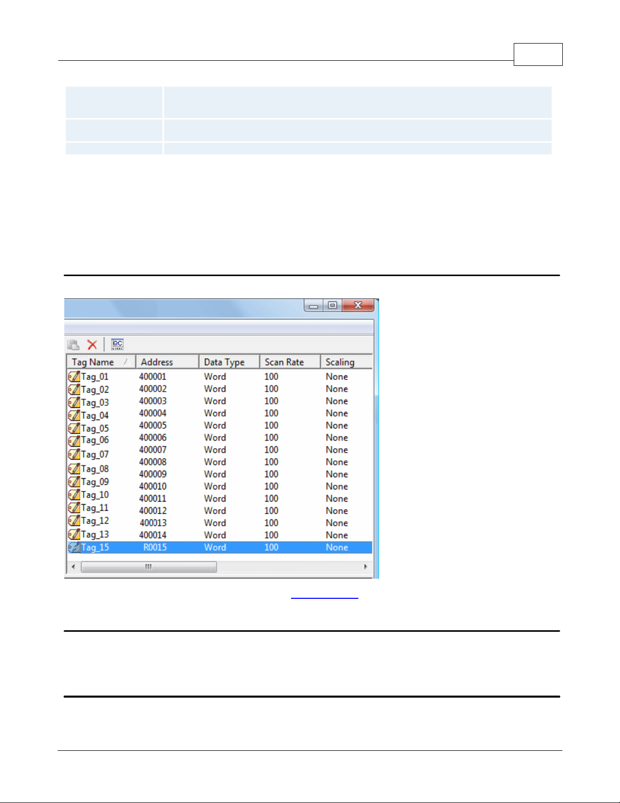
KEPServerEX5 Help
data. When this occurs, the scaled value is also forced outside of the established range. To
prevent this from occurring, the High and Low Clamps can be used to constrain the scaled
value to the range specified.
Units
The server also allows a unit's string to be assigned to a scaled tag. The units' string can be
up to 32 characters long.
Negate scaled value
This parameter forces the resulting value to be negated before being passed to the client.
Note 1: The OPC server supports the OPC tag properties available in the 2.0 Data Access specifications. If the OPC
client being used supports these properties, it can automatically configure the range of objects (such as user input
objects or displays) by using the Scaling settings.
Note 2: With the server's full-time online operation, these parameters can be changed at any time. Changes made to
Tag Properties will take effect immediately; however, OPC clients that have already connected to the tag will not be
affected until they release and reacquire it. Utilize the User Manager to restrict access rights to server features in order
to prevent any unauthorized operator from changing these parameters.
70
Tag Selection
The Tag Selection dialog is used to quickly find an existing tag in the server project in order to select it for editing.
Note: Once a tag is selected, users will be returned to Tag Properties.
What is a Tag Group?
This server allows tag groups to be added to the project. Tag groups are used to tailor the layout of OPC data into
logical groupings that fit the application's needs. Tag groups allow multiple sets of identical tags to be added under the
same device: this can be convenient when a single device handles a number of similar machine segments.
Tag Group Properties
From an OPC client standpoint, Tag Groups allow users to segregate OPC data into smaller tag lists, thus making finding
specific tags easier when browsing the server. The following image used the supplied OPC Quick client to create Cell1
and Cell2 tag groups and simplify the OPC Client browsing.
www.kepware.com
Page 72

71
KEPServerEX5 Help
To add a new tag group to the project, right-click on either an existing device or tag group branch and select New Tag
Group from the context menu. Alternatively, click on either an existing device or tag group branch and then click the
New Tag Group icon on the toolbar.
When adding a new tag group to the project, users will be presented with the following dialog.
www.kepware.com
Page 73

KEPServerEX5 Help
Tag groups can be added at any level from the device-level down, and multiple tag groups can be nested together to fit
the application's needs. As seen in the OPC Quick Client dialog above, the fully qualified OPC item path is "Channel1.
Device1.Machine1.Cell1.Tag1". For this OPC item, "Machine1" and "Cell1" segments are nested tag groups.
Note: With the server's online full-time operation, these parameters can be changed at any time. Any changes made to
the tag groups will take effect immediately. If the name is changed, OPC clients that have already used that tag group
as part of an OPC item request will not be affected until they release the item and attempt to reacquire it. New tag
groups added to the project will immediately allow browsing from an OPC client. Utilize the User Manager to restrict
access rights to server features in order to prevent operators from changing the parameters.
72
What is the Alias Map?
The Alias Map provides both a mechanism for backwards compatibility with legacy server applications as well as a way
to assign simple alias names to complex tag references. This is especially useful in client applications that limit the size
of tag address paths. Although the latest version of the server will automatically create the alias map, users can add
their own alias map entries to compliment those created by the server. Users can also filter the server created aliases
so that the only ones visible are their own.
Alias Map elements can be added, edited, deleted, exported and imported by clicking on the appropriate icon buttons in
the Alias Map window. The Alias Properties dialog allows an alias to be added or edited. The image below displays the
various alias map entries generated for the server project.
Descriptions of the icons are as follows.
To create a new Alias, click .
To edit an existing alias, select the alias from the list and then click .
www.kepware.com
Page 74

73
Note: Check or uncheck the Show aliases for system generated groups check box in order to show or hide the
server created aliases.
See Also: How to Create and Use an Alias
KEPServerEX5 Help
To delete manually created aliases, click .
To import an alias map as a .CSV file, click .
To export an alias map as a .CSV file, click .
Alias Properties
The Alias Map allows a way to assign simple alias names to complex tag references that can be used in client
applications. An alias is constructed by entering an alias name and then clicking on the desired device name or group
name.
Descriptions of the Alias Properties are as follows.
Alias Name: This parameter is used to enter the alias name, which can be up to 256 characters long. It must be
unique in the alias map.
Mapped To: This parameter specifies the location of the Alias. Because the alias map does not allow tag items to
be browsed from the alias table, users should create a simple name that replaces the address that leads up to
the tag. This will make is easier to address items in a client application that does not support tag browsing.
Scan rate override: This selection is used to specify an update rate that will be applied to all DDE and most
other non-OPC tags accessed using this alias map entry. This setting is equivalent to the Topic update rate found
in many DDE only servers. The valid range is 0 to 99999990 milliseconds. The default is 0 milliseconds. When set
to 0 milliseconds, the server will observe the DDE scan rate set at the individual tag level using the Tag
Properties dialog.
Scan rate override: This selection is used to specify an update rate that will be applied to all DDE/FastDDE/
SuiteLink and most other non-OPC tags accessed using this alias map entry. This setting is equivalent to the
www.kepware.com
Page 75

KEPServerEX5 Help
Topic update rate found in many DDE only servers. The valid range is 0 to 99999990 milliseconds. The default is
0 milliseconds. When set to 0 milliseconds the server will observe the DDE scan rate set at the individual tag
level using the Tag Properties dialog.
Once the desired path has been selected and the DDE scan rate has been set, click OK to complete the alias. To enter
more alias map elements, return to the Alias Map dialog.
74
Designing a Project
Although this server is designed for easy usage, there are several steps required to create, configure and run a project.
Utilize the server's User Interface to build a project, starting by selecting the specific communications driver,
configuring its parameters and then adding user-defined tags as necessary. Before beginning, refer to System
Requirements.
The following steps provide guidance on the process of building a project. Throughout this example, a number of
additional help links will be presented in order to provide supplemental information. Use the Back button on the help
system's toolbar to return to the example. Select a link below to jump to a specific page.
Running the Server
Starting a New Project
Adding and Configuring a Channel
Adding and Configuring a Device
Adding User-Defined Tags
Adding Tag Scaling
Saving the Project
Testing the Project
Note: The examples in the following pages use the Simulator driver supplied with the server. The Simulator driver is a
memory-based driver that provides both static and changing data for demonstration purposes. The Simulator driver
does not have the broad range of configuration options found in many other communication drivers; thus, some
examples may require additional screen shots to demonstrate specific product features that are present when using one
of the normal communication drivers. In these cases, screen shots will be provided.
Running the Server
Although this server runs as a service by default, users can choose to run it on the desktop. When running as a service,
the server is online all the time. When running as a desktop application, the OPC client can automatically invoke the
server when it attempts to connect and collect data. In order for either process to occur correctly, users must first
create and configure a project. When invoked, the server automatically selects the most recently used project.
Initially, however, users need to manually invoke the server using the desktop icon, the Windows Start menu or by
selecting Configuration in Administration on the System Tray. The image below displays the invoked interface
(although its appearance may differ depending on any changes that may have been made). For more information on
the Configuration's elements, refer to Basic Server Components.
www.kepware.com
Page 76
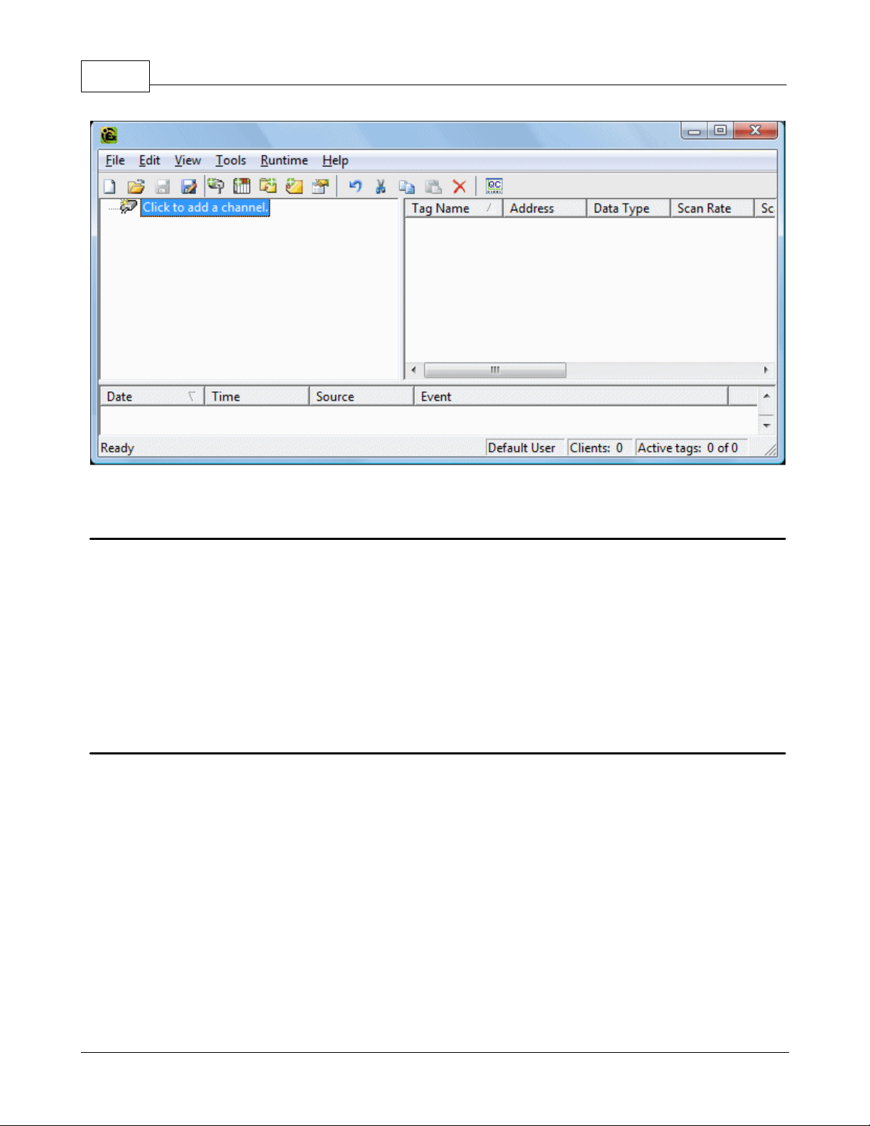
75
Note: Now that the server is running, a project may be created.
KEPServerEX5 Help
Starting a New Project
This server must be configured to determine what content it will provide while operating. For a server project, the
content that is determined will define channels, devices, optional tag groups and tags. These factors exist in the context
of a project file. As with many applications, users can define a number of project files and save and load them as
needed.
Most of the configuration needed within the server is contained within a project file; however, there are also a number
of configuration options that are global and are applied to all projects. These global options are configured in the Tools
| Options menu. Options include General Options, Runtime Connection Options, Event Logger Options, OPC Options
and Compliancy Options. Furthermore, all global options are stored in a Windows INI file called "Servermain.INI" and
set in the Windows registry. This file is located in the server's root directory. While it is normal practice to store global
options in the Windows registry, an INI file allows users to move the global settings easily from one machine to
another.
Adding and Configuring a Channel
The first step in creating a new project is determining the communications driver(s) required by the application. In the
server, a communications driver is referred to as a channel. Users can define a number of channels within a single
project, depending on the driver or drivers installed.
Note: The Simulator Driver is used in this example.
1. To add a new channel to the project, click Edit | Devices | New Channel. Alternatively, click the New Channel icon
on the toolbar or right-click and select it on the context menu. Selecting New Channel by all of these methods will
invoke the Channel Wizard, which is used to both name the channel and select a communications driver.
www.kepware.com
Page 77

New Channel by Edit | Add Channel
KEPServerEX5 Help
76
New Channel by Context Menu
2. For simplicity, leave the channel name "Channel1."
3. Select the communications driver that will be applied to this channel. For this example, choose the Simulator
driver from the driver selection drop-down menu.
Note: For this driver, the Next dialog is the Channel Summary. In other applications, there will be additional dialog
pages that allow the configuration of parameters such as communications port, baud rate and parity.
Thus, while not used by the Simulator driver, the following figure demonstrates the communications dialog that is
common to all drivers that use the serial port.
4. To complete the addition of the channel, click Next | Finish.
www.kepware.com
Page 78

77
Important: A a small red "x" should be visible below the channel icon. This denotes that the channel does not contain
a valid configuration because no devices have been added yet.
Note: This server supports the use of multiple channels. As channels are added to the project, users can specify either
the same communications driver or different communications drivers. All communication drivers offer support operation
on up to 100 communications ports or Ethernet network connections simultaneously. Select drivers offer support for
256 channels. By defining multiple channels, users can improve the application's overall performance. Both serial
drivers and Ethernet drivers benefit from using multiple channels because it spreads out large communications loads. A
good example of this would be a serial driver that is being used to communicate with eight devices on the serial line.
Normally, the communications driver used in this application would be responsible for gathering data from all eight
devices. If this same application is reconfigured to use multiple channels assigned to multiple communications ports,
the device load can be divided across the channels. The end result is a reduced workload on each channel and dramatic
improvements in the application's responsiveness. The need to use multiple channels depends solely on the needs of
the application. In either case, there is no additional cost involved to use a licensed driver on multiple communications
or Ethernet ports.
KEPServerEX5 Help
Adding and Configuring a Device
Once a channel has been defined in a project, a device must then be added to the channel. A device identifies the
physical node or station on a communications link. A device can also be thought of as a way of framing the definition of
a connection to a specific point of interest in the application. In this respect, a device would still be used as a term
when describing the connection to a database object. In this example, "device" refers to a specific device on a network.
In the Simulator driver, a device supports multiple device nodes and allows users to simulate networked devices.
1. To add a device, select the channel to which the device will be added. Next, click Edit | New Device. Alternatively,
click the Add Device icon on the toolbar or right-click and select Add Device from the context menu. Selecting New
Device by all of these methods will invoke the Device Wizard, which is used to both name the device and set its Node
ID.
New Device by Edit | New Device
www.kepware.com
Page 79

KEPServerEX5 Help
New Device by Context Menu
2. For simplicity, leave the device name "Device1."
Note: The number of dialog pages in the Device Wizard depends on the driver being used in the application.
3. Click Next to proceed to the next dialog. Then, select either a 16 bit or 8 bit register size for the device being
simulated. In other device drivers, users would select a device model. For this example, however, choose the 16 bit
device size.
4. Then select the Device ID, which is the unique identifier required by the actual communications protocol. For the
Simulator driver, the Device ID is a numeric value. The format and style of the Device ID depends on the
communications driver being used.
Note: For this driver, the next dialog is the Device Summary. In other applications, there will be additional dialog pages
that allow the configuration of parameters such as device timeout and retry count.
Thus, while not used by the Simulator driver, the following figure demonstrates the Timeout dialog that is common to
all communications drivers.
78
www.kepware.com
Page 80
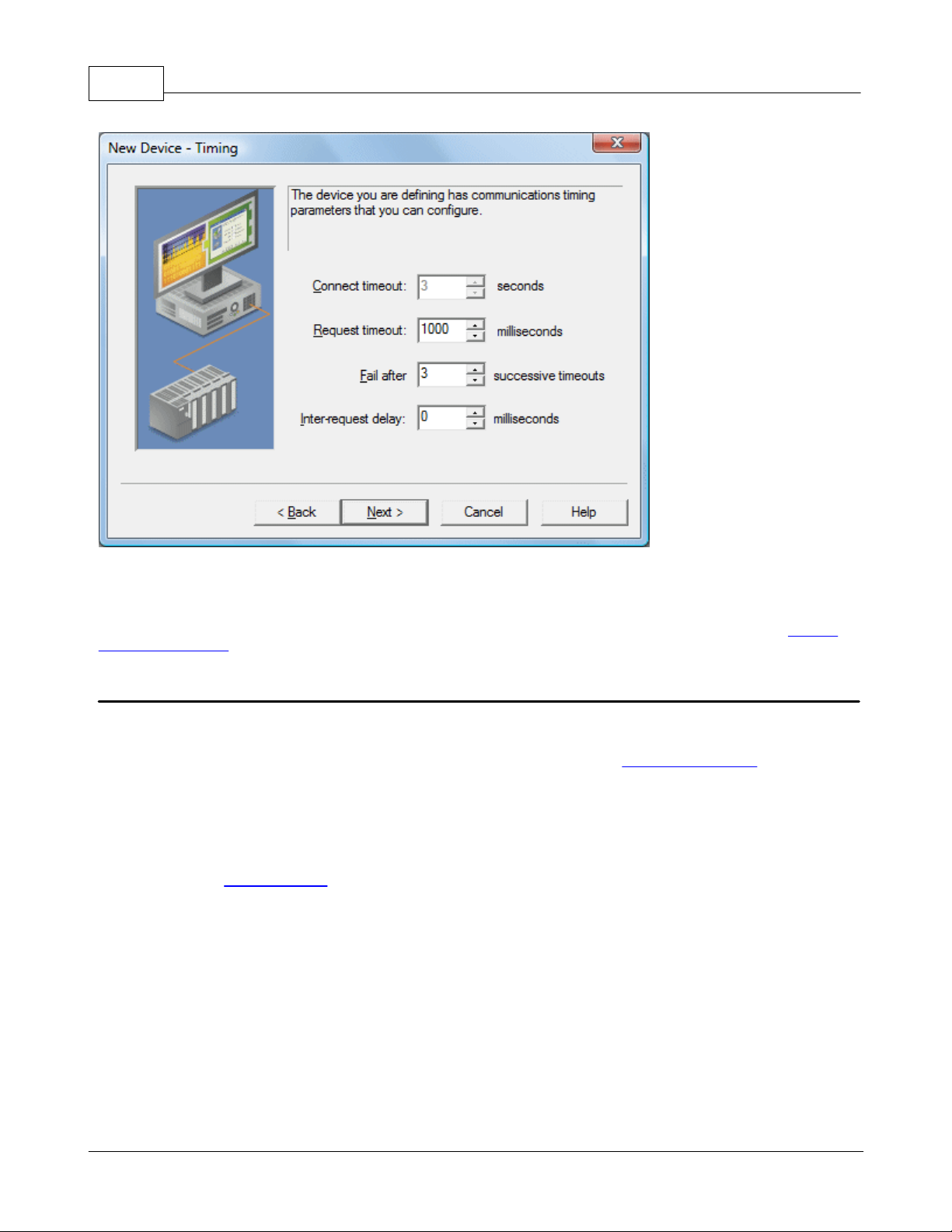
79
KEPServerEX5 Help
5. To complete the addition of the device, click Next | Finish.
Note: The server is now ready to start providing data to OPC clients. With the server's online full-time mode of
operation, the server can start providing OPC data immediately. At this point, however, the configuration can potentially
be lost since the project has not yet been saved. Before saving, users can add tags to the server. See Also: Adding
User-Defined Tags.
Adding User-Defined Tags
There are two ways to use the server to get data from a device to the client application. The first and most common
method requires that users first define a set of tags in the server project and then use the name previously assigned to
each tag as the item of each link between the client and the server. This method makes all user-defined tags available
for browsing within OPC clients. User-defined tags also support scaling. See Also: Adding Tag Scaling.
1. To add a tag to the project, first select a device name from the Channel/Device tree view within the server. The Tag
dialog below uses the example project and has "Device1" as the currently selected device.
2. Next, click Edit | New Tag. Alternatively, right-click on the device and select Add Tag from the Context Menu or
click the toolbar's Add Tag icon. Selecting Add Tag by all of these methods will invoke Tag Properties, a dialog in which
users set the tag name, specify a device-specific address, select a data type and set the tag's access method. Before
continuing, refer to Tag Properties for terminology.
www.kepware.com
Page 81

Add Tag by Edit | New Tag
KEPServerEX5 Help
80
Add Tag by Context Menu
3. Edit the controls to match the following content (as shown in the Tag dialog image).
Tag Name: MyFirstTag
Address: R000
Description (Optional): My First Simulator Tag
Data Type: Word
Client Access: Read/Write
Scan Rate: 100 milliseconds*
*This does not apply for OPC tags.
Note: The Address, Data Type and Client Access fields depend on the communications driver being used. With the
Simulator driver, "R000" is a valid address. The address "R000" supports a data type of "Word" and client access rights
of "Read/Write;" however, this will obviously not be the case with every communications driver. To aid users in
determining the correct settings for their driver, there is the Hints function. To use Hints, click on the question mark
icon in Tag Properties. This will invoke the driver-specific tag information (such as available addresses and data types).
For the Simulator driver, Hints appears as follows.
www.kepware.com
Page 82

81
For additional information, click the Help button in the Hints dialog. This invokes the driver specific help documentation
at the page that covers data addressing for the device currently selected.
4. Commit the tag to the server by pressing Apply in Tag Properties. The tag should now be visible in the Tag View
area of the server. If only one tag needed to be added, users would be finished at this point. For this example,
however, a second tag needs to be added for use in Tag Scaling.
5. If Apply has already been pressed, click the New icon in Tag Properties. This clears all of the fields and returns them
to their default state. Enter the following data:
KEPServerEX5 Help
Tag name: MySecondTag
Address: K000
Description: My First Scaled Tag
Data Type: Short
Client Access: Read/Write
Scan rate: (Doesn't Apply)
6. Next, press Apply to commit the second tag.
Note: When entering tag information, users can and will be presented with an occasional error message. The error
messages presented will be generated by either the server or the driver. The server will generate error messages when
users attempt to add a tag using the same tag name as an existing tag. The communications driver will generate errors
for three possible reasons:
1. If there are any errors entered in the format or content of the address field, including errors in the address range
of a particular device specific data item.
2. When the data type selected is not available for the address that has been entered.
3. If the client access level chosen is not available for the address that has been entered.
In each of these cases, the error message will be specific in describing the error. The error message will also provide
the option of directly invoking the driver specific help documentation in order to help remedy the problem.
Dynamic Tag Addressing
Dynamic Tag Addressing is another way of defining tags. Dynamic tags are used to define tags solely in the client
application. Instead of creating a tag item in the client that addresses another tag item that has been created in the
server, users only need to create a tag item in the client that directly accesses the device address.
Note 1: The server creates a special Boolean tag for every device in a project that can be used by a client to determine
whether that device is functioning properly. To use this tag, specify the item in the link as Error. The value of this tag is
zero if the device is communicating properly; otherwise, it is one.
Note 2: If a device address is used as the item of a link, such that the address matches the name of a user-defined tag
in the server, the link will reference the address pointed to by the user-defined tag. Furthermore, with the server's
online full-time operation, users can technically begin using this project in an OPC client at this moment. For the sake of
work preservation, proceed to Saving and Testing the Project.
www.kepware.com
Page 83

KEPServerEX5 Help
82
Adding Tag Scaling
When defining a new tag in the server, users have the option of applying tag scaling, which allows raw data from the
device to be scaled to an appropriate range for the application. There are two types of scaling: Linear and Square Root.
For more information, refer to Tag Scaling.
Note: The image below uses the second tag previously developed in this example. The Tag Properties dialog should
appear as shown below.
1. To add scaling to this tag, click on the Scaling tab to open the Scaling Properties. Then edit the content of the dialog
to match the following.
www.kepware.com
Page 84
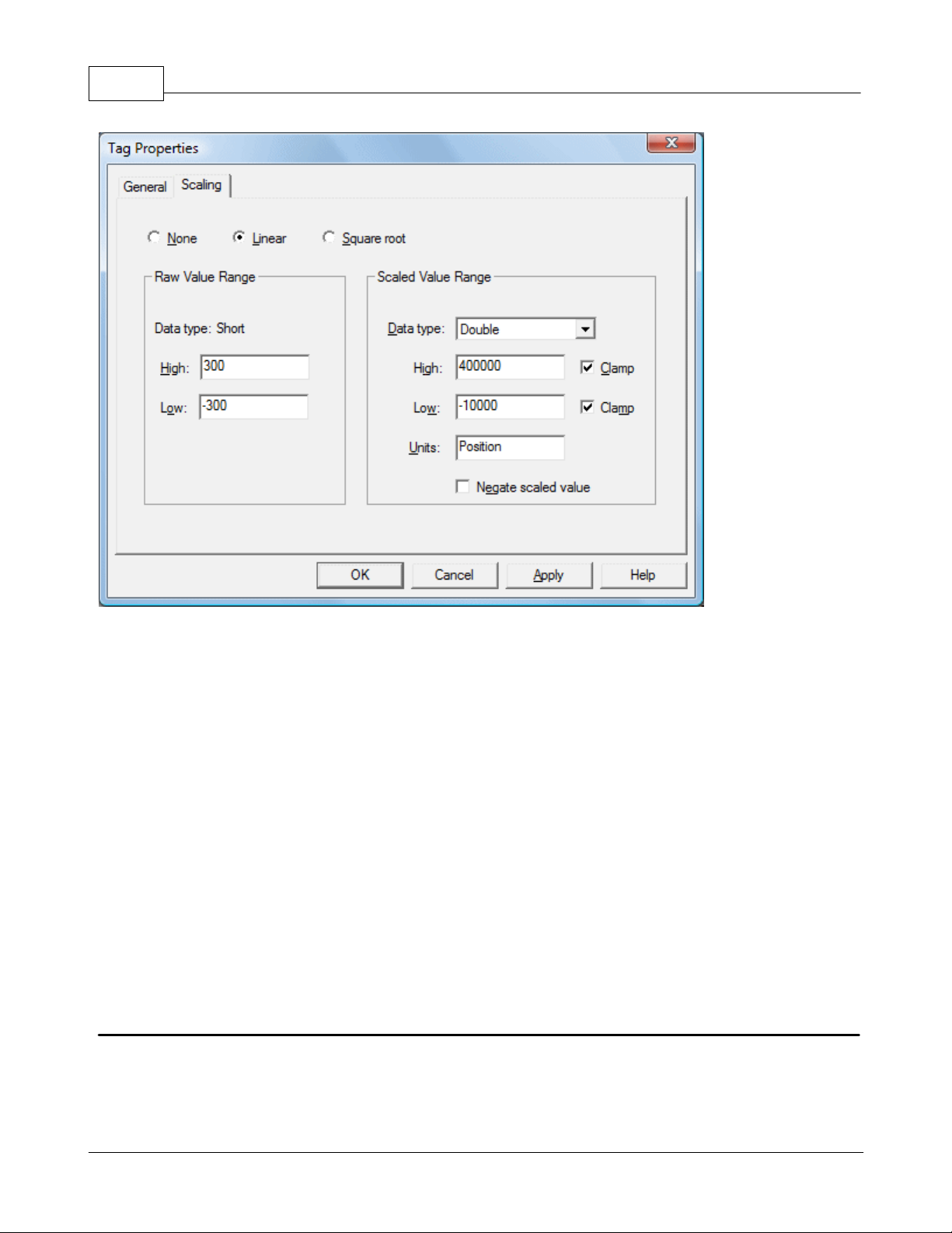
83
KEPServerEX5 Help
2. In this example, Linear Scaling has been selected. The raw value range allows users to specify what they expect to
receive as a data range from the actual device. The scaled data type also allows users to specify how the resulting
scaled value is presented to the OPC client application. The scaled value range is used to specify the desired range in
engineering units for the resulting value. By applying the high and low clamps, users can ensure that their output will
always stay within the configured limits. This may not always be the case. If the raw data exceeds the range set by the
raw value High and Low, it forces the scaled value beyond the range that has been entered for the scaled value. The
clamps prevent this from occurring.
3. The Units field allows users to provide a string to the OPC client that describes the format or unit for the resulting
engineering value. In order to use the Units field, an OPC client that can access the Data Access 2.0 tag properties data
is required. If the client does not support these features, there is no need to configure the Units field.
4. Once the data has been entered as shown above, click OK or Apply to commit the scaling changes.
Dynamic Addressing
Dynamic Tag Addressing is the second method for defining tags. Dynamic tags are used to define tags solely in the
client application. Instead of creating a tag item in the client that addresses another tag item created in the server,
users only need to create tag items in the client that directly accesses the device driver's addresses. On client connect,
the server will create a virtual tag for that location and start scanning for data automatically.
Note: If the data type is omitted, the driver will choose a default data type based on the device and address being
referenced. The default data types for all locations are documented in the individual driver help documentation. If the
data type specified is not valid for the device location, the server will not accept the tag and an error will be posted in
the Event Log window.
Saving the Project
If each step in this example has been followed correctly, there should now be a project configured with two userdefined tags that are ready to be saved. How the project is saved varies and depends on whether a Runtime project
or an offline project is being edited.
When editing projects in the Runtime, the server's online full-time operation allows tags to be accessed immediately
from an OPC client once it has been saved to disk. The changes are made to the actual project, so users save by
www.kepware.com
Page 85

KEPServerEX5 Help
clicking File | Save. Users can overwrite the existing project or save the edits as a new project. They are also given the
option of loading the new project as the default Runtime project.
When editing projects offline, users have the option to save to the same project or to save as a new project. Once
completed, users can click Runtime | Connect and then load the new project as the default Runtime project.
Note: An OPC client application can automatically invoke an OPC server when the client needs data. The OPC server,
however, needs to know what project to run when called upon in this fashion. The server will load the most recent
project that has been loaded or configured. To determine what project the server will load, look to the Most Recently
Used file list found in File. The loaded project will be the first project file listed.
84
Testing the Project
The server includes a full-featured OPC Quick Client, which supports all of the operations available in any OPC client
application. Users can utilize the Quick Client to access all of the data available in the server application. The quick
client is used to read and write data, perform structured test suites and test server performance. It also provides
detailed feedback regarding any OPC errors returned by the server.
1. Locate the OPC Quick Client program in the same program group as the server.
2. Run the OPC Quick Client. The following dialog will be invoked.
www.kepware.com
Page 86

85
KEPServerEX5 Help
Establishing a Connection
3. Next, establish a connection by clicking Edit | New Server Connection. Alternatively, right-click and select New
Server Connection from the Context Menu or click the New Server icon on the toolbar. Selecting New Server Connection
by all of these methods will invoke the OPC Server Selection dialog, which is used to make connections with an OPC
Server either locally or remotely via DCOM.
Connect to Server by Edit | New Server Connection
www.kepware.com
Page 87

KEPServerEX5 Help
Connect to Server by the Context Menu
Note 1: By default, the Server Selection dialog is configured with the Prog ID of the server. The name listed in the
server connection dialog is called the Prog ID of the server. OPC clients use this name to reference a specific OPC
server. The server connection dialog should appear as shown below.
86
Note 2: Once a connection is made, two things may happen. If the server is running, the OPC Quick Client will simply
make a connection to the server. If the server is not running, it will start up automatically.
Adding a Group
4. Next, add a group needs to the connection. To do so, select the server connection and then click Edit | New Group.
Alternatively, right-click and select New Group from the context menu or click the New Group icon on the toolbar.
Selecting New Group by all of these methods will invoke the Group Properties dialog, which is used to configure how the
group interacts with the OPC server.
Note: Groups act as a container for any tags that will be accessed from the server. All OPC clients use groups to access
OPC server data. Aside from providing a container for lists of tags, OPC groups also provide control over how tags are
updated. There are a number of properties attached to a group that allow the OPC client to determine how often data
should be read from the tags, whether the tags are active or inactive, whether a dead band applies and etc. These
properties let the OPC client control how the OPC server operates. For more information on Group Properties, refer to
the OPC Quick Client help documentation.
www.kepware.com
Page 88

87
Adding a Group by Toolbar Icon
KEPServerEX5 Help
Adding a Group by Context Menu
5. For the purposes of this example, edit the Group Properties parameters so that they match the following image.
Note: The Update Rate, Percent Dead Band and Active State parameters control when and if data will be returned
for the group's tags. The Update Rate determines how often data will be scanned from the actual device. It
determines how often data will be returned to the OPC client as a result of that scan. The Percent Dead Band is used
www.kepware.com
Page 89

KEPServerEX5 Help
to eliminate or reduce noise content in the data by only detecting changes when they exceed the percentage change
that has been requested. The percent change is a factor of the data type of a given tag. The Active State is used to
turn all of the tags in this group either on or off. The Group Name is used for reference from the client and can
actually be left blank.
6. Press OK to commit the group when finished.
88
Accessing Tags
7. OPC server tags must be added to the group before they can be accessed. OPC Data Access specifications defines a
tag browsing interface as one that allows an OPC client to directly access and display the available tags in an OPC
server. By allowing the OPC client application to browse the tag space of the OPC server, a user can simply click on the
desired tags to automatically add them to a group.
8. Select the group in which tags will be placed. Then, click Edit | New Item. Alternatively, right-click and select New
Item from the Context Menu or click the New Server icon in the toolbar. Selecting New Item from all of these methods
will invoke the Add Items dialog, which is used to enter an Item ID, Data Type and Active State for an OPC item
Note: The Add Items dialog also provides a tree view of the Browsing section and can be used to browse into an OPC
server to find tags configured at the server. Using the "Example1" project created as part of this example, users can
access the tags previously defined by expanding the branches of the view.
9. Once the tree hierarchy is at the point shown in the image above, users can begin adding tags to the OPC group by
double-clicking on the tag name. As tags are added to the group, the Item Count shown at the bottom of the Add
Items dialog will increase to indicate the number of items being added. If both "MyFirstTag" and "MySecondTag" were
added, the item count should be 2.
10. When finished, commit the tags to the group by clicking OK.
Note: Users should now be able to access data from the server using the two tags that were defined. The OPC Quick
www.kepware.com
Page 90

89
Client should appear as shown below.
KEPServerEX5 Help
The first tag, "MyFirstTag," should contain a changing value. The second tag should be zero at this point. If users only
needed to test the reading of an OPC item, they are now finished. If, however, users desired to change an OPC item,
they can use one of the write methods to send new data to the OPC item.
Writing Data to the OPC Server
The OPC Quick Client supports two methods for writing data to an OPC server: Synchronous Writes and
Asynchronous Writes. Synchronous Writes perform a write operation on the OPC server and wait for it to
complete. Asynchronous Writes perform a write on the OPC server but doesn't wait for the write to complete. Users
can choose either method when writing data to an OPC: the different write methods are more of a factor in OPC client
application design.
11. To write to an OPC item, first select the item and right-click to display its context menu. Then, select either
Synchronous or Asynchronous Writes. Both choices will invoke the Write Dialog. For the purpose of this example, rightclick on "MyFirstTag" and select Asynchronous Write.
Note: Although the Write Dialog is displayed, the value will continue to update. Users can enter a new value in for this
item by clicking in the item's Write Value and then entering a different value. Once completed, the Apply button will
become active. Press Apply to write the data. Apply allows users to continue to write new values: OK writes the new
value but also closes the dialog. Thus, once users are finished making changes, they can exit the dialog by pressing OK
www.kepware.com
Page 91

KEPServerEX5 Help
. If no new data has been entered, clicking OK will not send data to the server.
90
Conclusion
At this point, all of the basic steps involved in building and testing an OPC project have been discussed. Users are
encouraged to continue to test various features of both the server and the OPC Quick Client for greater understanding
and comprehension. For more information on the OPC Quick Client, refer to its help documentation.
If the basic terminology and concepts are understood, users can begin developing their OPC application. If using Visual
Basic, please refer to the supplied example projects. These two projects provide both a simple and complex example of
how OPC technology can be used directly in Visual Basic applications.
New Channel - Name
This server supports the use of simultaneous multiple communications drivers. Each protocol or driver used in a project
is called a Channel, which refers to a specific communications driver. A server project can consist of many channels,
each with either unique communications drivers or with the same. A channel acts as the basic building block of an OPC
link. Its properties control parameters such as communications port, baud rate and parity.
In a server project, each Channel Name must be unique and can be up to 256 characters long. Although using
descriptive names is usually a good idea, some OPC client applications may have a limited display window when
browsing the tag space of an OPC server.
Note: The channel name entered will be part of the OPC browser information.
New Channel - Driver Page
After a name has been entered for the new channel, a communications driver must be selected from the "Device
driver:" drop-down list. The drop-down list's contents depend on the communications drivers currently installed on the
PC. The list will contain the drivers available for use in the server project.
www.kepware.com
Page 92
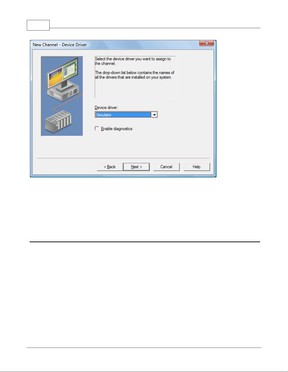
91
KEPServerEX5 Help
Since the server supports the use of simultaneous multiple communications drivers, users can add a number of
channels to the project. It is not necessary to select a different communications driver for each channel. Many of the
communications drivers available for the server support operation on either multiple communications ports or across
multiple network connections. If the driver chosen does not support multiple channels (or if the number of supported
channels has been exceeded) the driver will display a dialog stating so.
Another server feature is the ability to run Channel Diagnostics. Users can select the Enable Diagnostics check box
in order to make diagnostic information available to the OPC application. When diagnostic functions are enabled,
Diagnostic Tags will be available for use within client applications. A Diagnostic Window will also be available when
this feature is enabled.
New Channel - Communications
After a device driver has been selected, suers need to set up its communications. The server supports several mediums
for communications; thus, the Communications dialog's format will vary depending on the driver's requirements.
www.kepware.com
Page 93
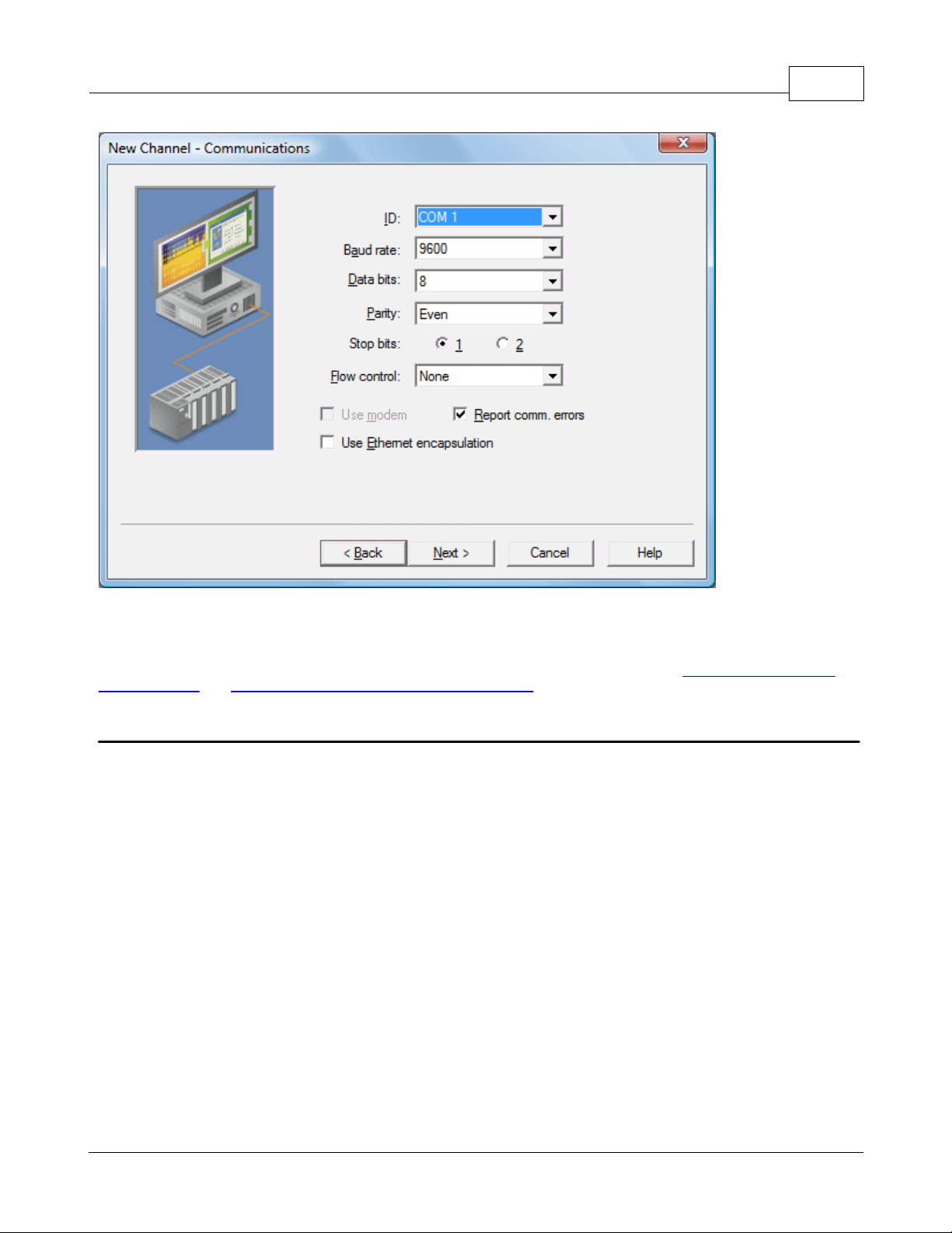
KEPServerEX5 Help
92
For Serial based drivers, the Communications dialog is used to set the Serial Port, Baud rate, Data bits, Parity, Stop bits
and RTS/DTR Flow Control.
Note: The dialog's additional options allow users to select and use dial-up Modem support or Ethernet Encapsulation for
connecting to devices via Serial to Ethernet terminal servers. For more information, refer to Using a Modem in the
Server Project and Device Properties - Ethernet Encapsulation.
New Channel - Summary
The Channel Summary dialog allows users to review the selections they have made while defining the channel. If a
mistake is found upon review, users can simply click the Back button until the required dialog is displayed. After
making changes, users can click the Next button to return to the Summary page. Once satisified with the Channel
Summary, click Finish.
www.kepware.com
Page 94

93
KEPServerEX5 Help
New Device - Name
A Device Name can be the same from one channel to the next; however, each device under a channel must have a
unique name. The Device Name is a user-defined logical name for the device that can be up to 256 characters long.
While long descriptive names are generally good, some OPC client applications may have a limited display window when
browsing the tag space of an OPC server.
Note: The device name and channel name are part of the browse tree information.
www.kepware.com
Page 95

KEPServerEX5 Help
94
Note: Within an OPC client, the combination of channel name and device name would appear as ChannelName.
DeviceName.
New Device - Model
The Model parameter is used to select the device model associated with the Device ID. The Model selection drop-down
menu's contents will vary depending on the chosen communication driver. If a driver does not support model selection,
this option will be unavailable. If the communication driver does support multiple models, users should match the model
selection to the physical device. If the device being used is not represented in the model drop-down list, select a model
that conforms closest to the target device. This can be determined from the specific driver's help documentation.
Note: Some drivers support an Open model, which allows users to communicate without knowing the target device's
specific details.
www.kepware.com
Page 96

95
KEPServerEX5 Help
Note: With the server's online full-time operation, these parameters can be changes at any time. If the communications
driver supports multiple device models, the model selection can only be changed if there are currently no client
applications connected to the device. Since the device is being added at this time, any model can be selected. Utilize
the User Manager to restrict access rights to server features and prevent operators from changing parameters.
New Device - ID
The Device ID parameter is used to specify a device's driver-specific station or node. The type of ID entered will vary
depending on the communication driver being used. For example, many communication drivers use a numeric value. As
shown in the image below, when a driver supports a Numeric ID, the menu option allows users to enter a numeric
value. The numeric value's format can be changed to suit the needs of either the application or the communication
driver's characteristics. The format is set by the driver by default. Possible formats include Decimal, Octal and
Hexadecimal.
www.kepware.com
Page 97

KEPServerEX5 Help
96
If the communications driver is either Ethernet-based or supports an unconventional station or node name, the dialog
shown below may be displayed. In this case, the Device ID is a TCP/IP ID. TCP/IP or UDP IDs consist of four values
separated by periods. Each value has a range of 0 to 255. Some Device IDs are string based.
Note: Depending on the communications driver being used, there may be more parameters that need to be defined in
the New Device - ID dialog. For more information on the driver's Device ID, refer to its help documentation.
www.kepware.com
Page 98

97
Note: With the server's online full-time operation, these parameters can be changed at any time. Any changes made to
the Device ID will take effect immediately. Utilize the User Manager to restrict access rights to server features and
prevent operators from changing parameters.
KEPServerEX5 Help
New Device - Timing
Device Timing parameters allow a driver's response to error conditions to be tailored to the application's needs. The
environment in which the application runs may require changes to the timing parameters. Factors such as electrically
generated noise, modem delays and bad physical connections can all influence how many errors or timeouts a
communications driver may encounter. The timing parameters are specific to each configured device.
Note: For most projects, the default Timeout settings work well. If users find that the project takes too long to time out
a device or that there are too many timeouts, they can adjust the settings to improve performance.
New Device - Summary
The Device Summary page allows users to review the selections that have been made for the device. If a mistake is
found upon review, users can simply click the Back button until the required dialog is displayed. After making changes,
users can click the Next button to return to the Summary page. Once satisified with the Device Summary, click Finish.
www.kepware.com
Page 99

KEPServerEX5 Help
98
Server Options
General Options
The server's online full-time mode of operation places some special requirements on the server as well as the operator.
Most parameters can be changed in the server at any time. This, although helpful, can cause many problems for OPC
applications. To prevent an operator from making a change that might disrupt the server's ability to provide data to
client applications, the server has warning pop-ups. These pop-ups are presented whenever a change will affect active
connections. Users can change the warning pop-ups' presentation through the General Option dialog.
Furthermore, saving the changes made to the project requires possible operator interaction. This can also be modified.
www.kepware.com
Page 100

99
KEPServerEX5 Help
Descriptions of the General Options dialog parameters are as follows.
Immediately attempt to establish a Runtime connection on start: This parameter is used to specify
whether the configuration tool will connect to the Runtime when started. It is checked by default. If it is
unchecked, users must manually connect.
Keep track of the __ most recently used project files: This parameter is used to specify how many project
files will be presented on the MRU (Most Recently Used) list of projects. The valid range is 1 to 16.
Always backup the last saved project prior to overwriting: Select this check box in order to have the
system automatically make a backup copy of the last saved (*.opf) project before overwriting it with a new
project file. The backup file will be named projectname.opf.bak and will be stored in the \Project Backups
folder.
CSV Import: The Delimiter setting is used to select the comma-separated variable that the server will use
while importing and exporting tag data in a CSV (comma separated variable) file. Users can select either the
default comma or a semicolon. See Also: Tag Management.
Confirmations: This parameter is used to specify the conditions that will force the server to present warning
pop-ups to an operator. When Deleting an object is enabled, all delete operations will invoke a warning popup
to be displayed to the operator that requires confirmation before the delete operation can be completed. When
Disconnect is enabled, all operations that would cause client applications to be disconnected from the server will
invoke a warning popup to be displayed that requires confirmation before the disconnect sequence can be
initiated. If Prompt to save is enabled, a popup will be invoked if the server is being shut down while the
project has outstanding changes. When connected to the Runtime and opening a project, Confirm Runtime
project replacement will warn that the project can be opened and edited offline.
Exit Options
The server supports the Data Access 2.0 server shutdown event. If an operator action will cause connections to OPC
clients that are using the 2.0 Data Access specifications to be lost, the server will issue a server shut down event to
those clients. If the clients are designed to utilize this event, they can properly disconnect their OPC resources. OPC
clients that do not support the server shutdown event may have issues once the server shuts down. When an OPC
server is invoked from a client application, the server automatically loads itself and begins running the last project
used. Normally when the OPC client is finished using the OPC server and disconnects, the OPC server would then exit.
Due to the server's online full-time mode of operation, the operator may have made changes to the project while it was
www.kepware.com
 Loading...