

Page 1
Preliminary
Thank you for purchasing HG1X Series product from IDEC. HG1X
Series Products are versatile operator interfaces with Windows based
configuration Software.
This manual will help you to
HG1X Products.
All the safety warnings and precautions must be followed to
ensure proper unit performance and personal safety.
Warnings used in this manual:
DANGER
CAUTION
safely
install, configure and operate
Danger Warnings are used to indicate
situations, locations and conditions that
can cause serious injury or death.
Caution Warnings are used to indicate
situations and conditions that can cause
operator injury and/or unit damage
We hope that you find this manual informative. If additional
information or technical assistance is needed please contact:
IDEC Corporation
1175 Elko Drive,
Sunnyvale,
CA 94089, USA
Tel - (800) 262-IDEC
Fax - (800) 635-6246
Website - www.idec.com
Manual Revisions:
If you contact us in reference to this manual, please include the
following revision number
Name: IDEC-HG1X Series Operation Manual
Revision: QMAN\HG1X\1001\Rev0
HG1X Series Products are intended to be operator interfaces,
IMPORTANT
to work with PLCs which actually take control actions. It is
assumed that the user is well acquainted with the PLC
system being used. Never use HG1X units to perform
emergency stop applications. It is advised that separate
switches be used outside the PLC for ANY emergency stops.
Any mechanical or electrical modification to this unit will
void all warranties.
Table of Contents
Preliminary............................................................ i
Contents................................................................ ii
1.0 Introduction........................................................... 1 - 1
1.1 Purpose of this manual................................... 1-1
1.2 Introduction to HG1X....................................... 1-1
1.3 HG1X Series: Specifications........................... 1-2
HG1X-252.............................................. 1-2
HG1X-452.............................................. 1-6
2.0 Hardware............................................................... 2-1
2.1 Mounting......................................................... 2-1
2.2 Power Requirements...................................... 2-2
2.3 Serial Port....................................................... 2-3
2.4 PLC Port......................................................... 2-4
3.0 Getting Started...................................................... 3-1
3.1 Introduction..................................................... 3-1
3.2 Application - Tags, Screens, Keys and Task... 3-1
3.3 PLC Communications..................................... 3-2
4.0 Understanding HG1X Features............................. 4-1
4.1 Screens.......................................................... 4-1
4.2 Keys............................................................... 4-3
4.3 Alarms............................................................ 4-5
4.4 Application Task-List....................................... 4-7
5.0 Configuration Software......................................... 5-1
5.1 Introduction to WindMSG Software................. 5-1
5.2 Installing WindMSG Software.......................... 5-2
5.3 WindMSG Software - Basics........................... 5-3
5.4 Create a new Application................................ 5-3
5.5 Setup Node..................................................... 5-4
5.6 Create Tag Data Base..................................... 5-5
5.7 Create Screens................................................ 5-6
5.8 Define Keys..................................................... 5-7
5.9 Define Alarms.................................................. 5-8
5.10 Application Task List........................................ 5-9
5.11 Download Application...................................... 5-10
6.0 How Do I?............................................................... 6-1
6.1 Frequently asked questions............................. 6-1
Appendix A: Examples to create Applications.... iii
Appendix B: Cable Diagrams.............................. iv
Page 2
Introduction
In this chapter. . . .
1.1 Purpose of this Manual
The intention of this Operation Manual is to provide a guide for Safe
installation, Configuration and operation of HG1X series models.
Purpose of this Manual
Introduction to HG1X
HG1X Series
HG1X-252
HG1X-452
Read this operation manual thoroughly before installing and
operating HG1X products.
This document is based on information available at the time of its
publication. While efforts have been made to be accurate, the
information in this document may not cover all the details or variations in hardware or software. Features described herein may not be
present in all hardwares. IDEC CORPORATION reserves the right to
update information in this publication without prior notice.
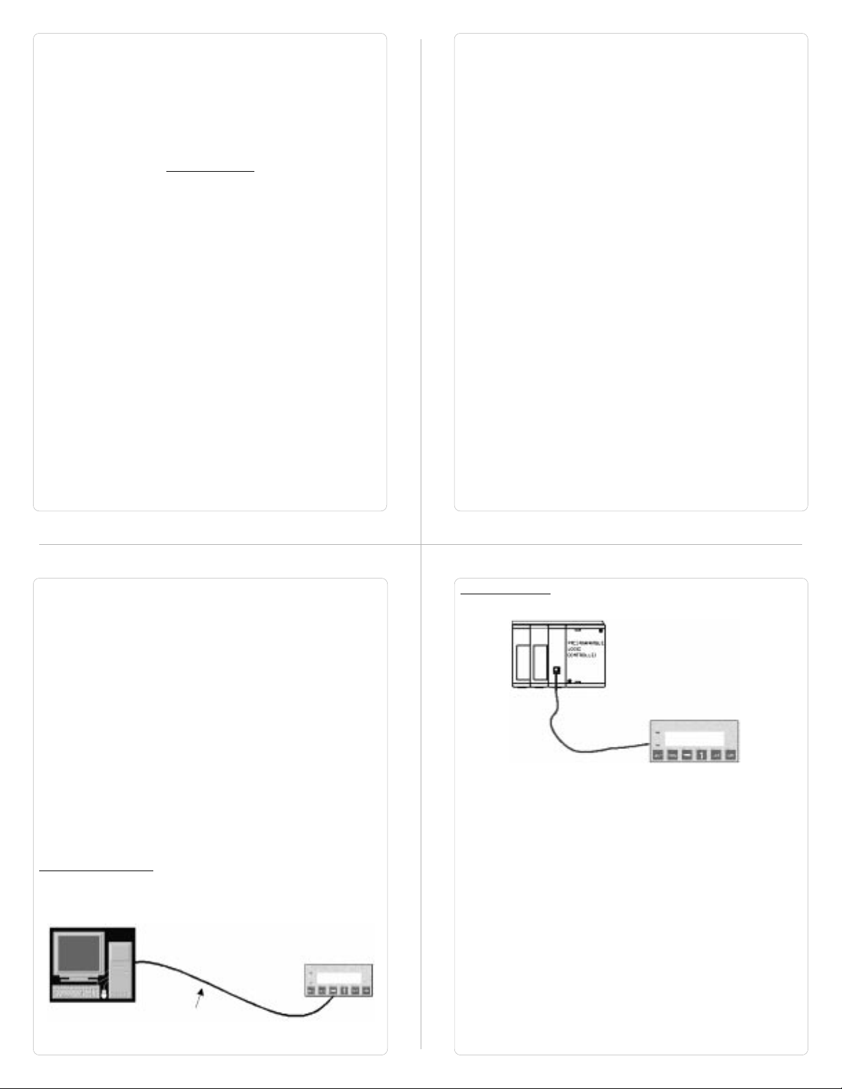
1.2 Introduction to HG1X
HG1X Series operator interfaces provide man-machine interface to
your PLC system. HG1X communicates with your PLC using serial
communication. HG1X models take power from PLC on their PLC
port.
Normal Operation:
Connect HG1X to PLC using the correct PLC-HG1X cable and your
HG1X is running.
Configuration of HG1X:
Each HG1X has to be configured using the WindMSG Software
before connecting it to the PLC.
Programming cable
for HG1X
Page 3
1.3 HG1X Series
Currently models included in the HG1X Series are as follows:
HG1X - 252 and HG1X - 452. HG1X Models take power from the
PLC. Detailed specifications for all the models is given in the
following section.
HG1X-252
Specifications:
Power: 5 VDC+ 5%, 130mA typically from PLC port
Display: 2 lines of 16 characters Backlit LCD
Bezel: IP65 rated Keypad
Keys: 6 User definable keys with tactile feedback
LEDs: 2 LEDs
Memory: 24K Application Memory
Communication: Two RS232 ports, one for connecting to
Temperature: 0 to 50 oC
Humidity: 10% to 90% (Non condensing)
Immunity to ESD: Level 3 as per IEC1000-4-2
Immunity to Transients: Level 3 as per IEC1000-4-4
Radiated Susceptibility: Level 3 as per IEC1000-4-3
Emissions: EN55011 CISPR A
System Components:
Note: User should order PLC cables and Software separately.
HG1X-252 unit with LCD display and Membrane keypad
-
- Installation Kit: Gasket, Two Mounting clamps, Two M4
screws, Four hex nuts.
the PLC and one for programming / serial printing.
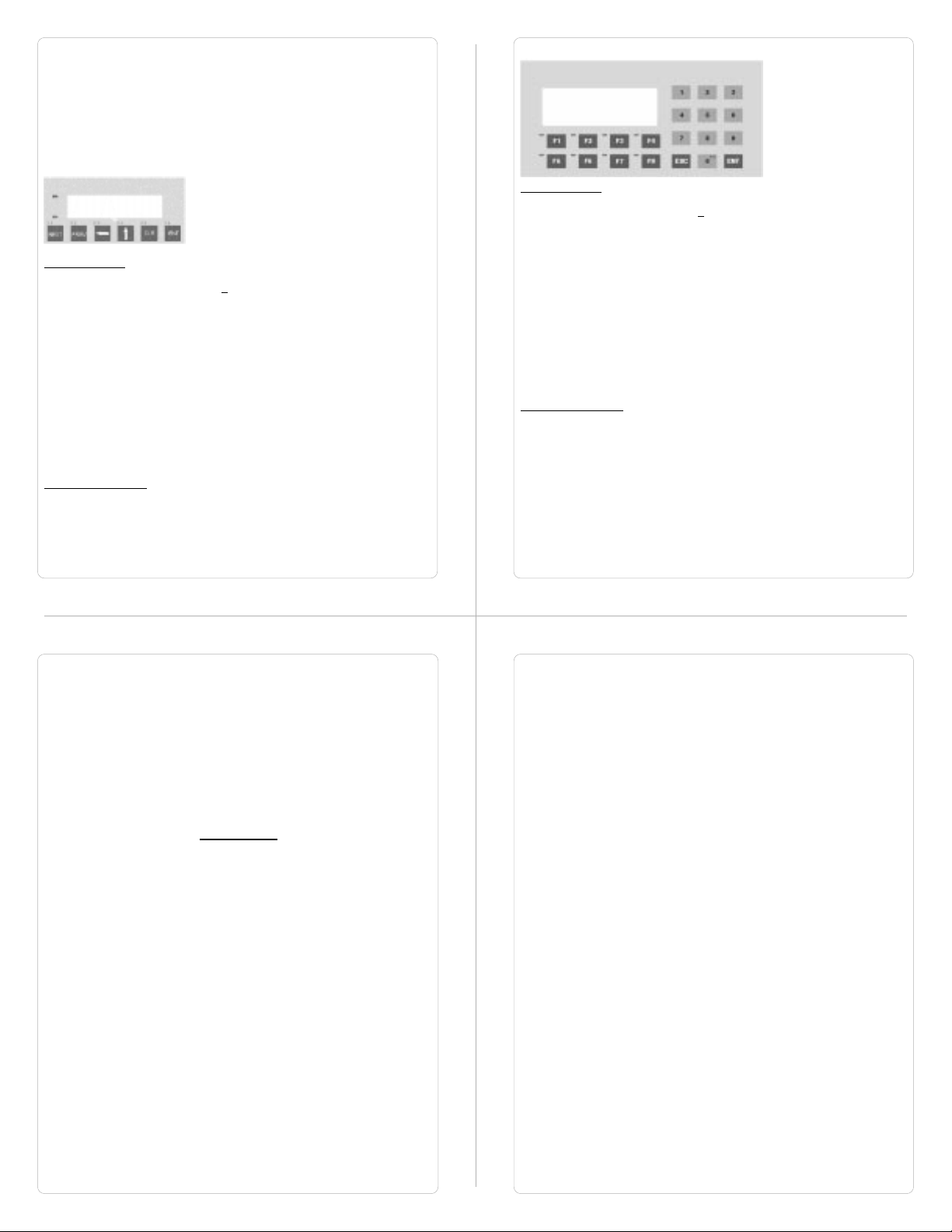
HG1X-452
Specifications:
Power: 5 VDC+ 5%, 140mA typically from PLC port
Display: 4 lines of 20 characters Backlit LCD
Bezel: IP 65 rated Keypad
LEDs: 8 LEDs
Keys: 20 User definable keys with tactile feedback
Memory: 24K Application Memory
Communication: Two RS232 ports, one for connecting to the PLC
and one for programming / serial printing.
Temperature: 0 to 50 oC
Humidity: 10% to 90% (Non condensing)
Immunity to ESD: Level 3 as per IEC1000-4-2
Immunity to Transients: Level 3 as per IEC1000-4-4
Radiated Susceptibility: Level 3 as per IEC1000-4-3
Emissions: EN55011 CISPR A
System Components:
- HG1X-452 unit with LCD display and Membrane keypad
- Insertable Legends
- Installation Kit: Gasket, Two Mounting clamps, Two M4
screws, Four hex nuts.
Note: User should order PLC cables and Software separately.
Hardware
In This Chapter. . .
Mounting, Panel Cutouts
Power Requirements
Serial Port
PLC Port
Page 4
This chapter is installation guide for HG1X Series.
2.1 Installation Instructions
HG1X should be mounted on a panel. Gasket, mounting screws and
clamps are provided with each HG1X unit for proper mounting.
Environmental Considerations:
Make sure that the unit is installed correctly and that the operating
limits are followed (see Specifications for HG1X). Do not operate
HG1X in areas subject to explosion hazards due to flammable gases,
vapors or dusts. HG1X should not be installed where fast temperature variations are present. Highly humid areas are also to be
avoided. High humidity causes condensation of water in the unit.
Location Considerations
Care should be taken when locating equipments behind the HG1X to
ensure that AC power wiring, PLC output modules, contactors,
starters, relays and any other source of electrical interference are
located away from HG1X. Particular care should be taken to the
position of Variable speed drives and switching power supplies.
Mounting
HG1X should be mounted on a panel. Dimensional sketch and Panel
cutout for each HG1X model is given in section 2.2. Clearance
behind the panel may vary with HG1X Model. Follow the procedure
given below for proper mounting:
1)Make a cutout of the required size. Panel cutout
tolerance is + 0.1mm.
2)Put the gasket behind the bezel. The gasket may be
sealed to the case using an adhesive.
3)Put the HG1X through the panel cutout.
4)Insert the clamps into the case.
5)Pullback the clips until they seat into the retaining
slots.
6)Tighten the clamping screws in an even pattern until
the HG1X is secured into the panel.
2.2 Dimensional Sketches and Panel Cutouts
This section presents the dimensional sketches and panel cutouts for
all the HG1X models. All dimensions are in mm. Not to Scale.
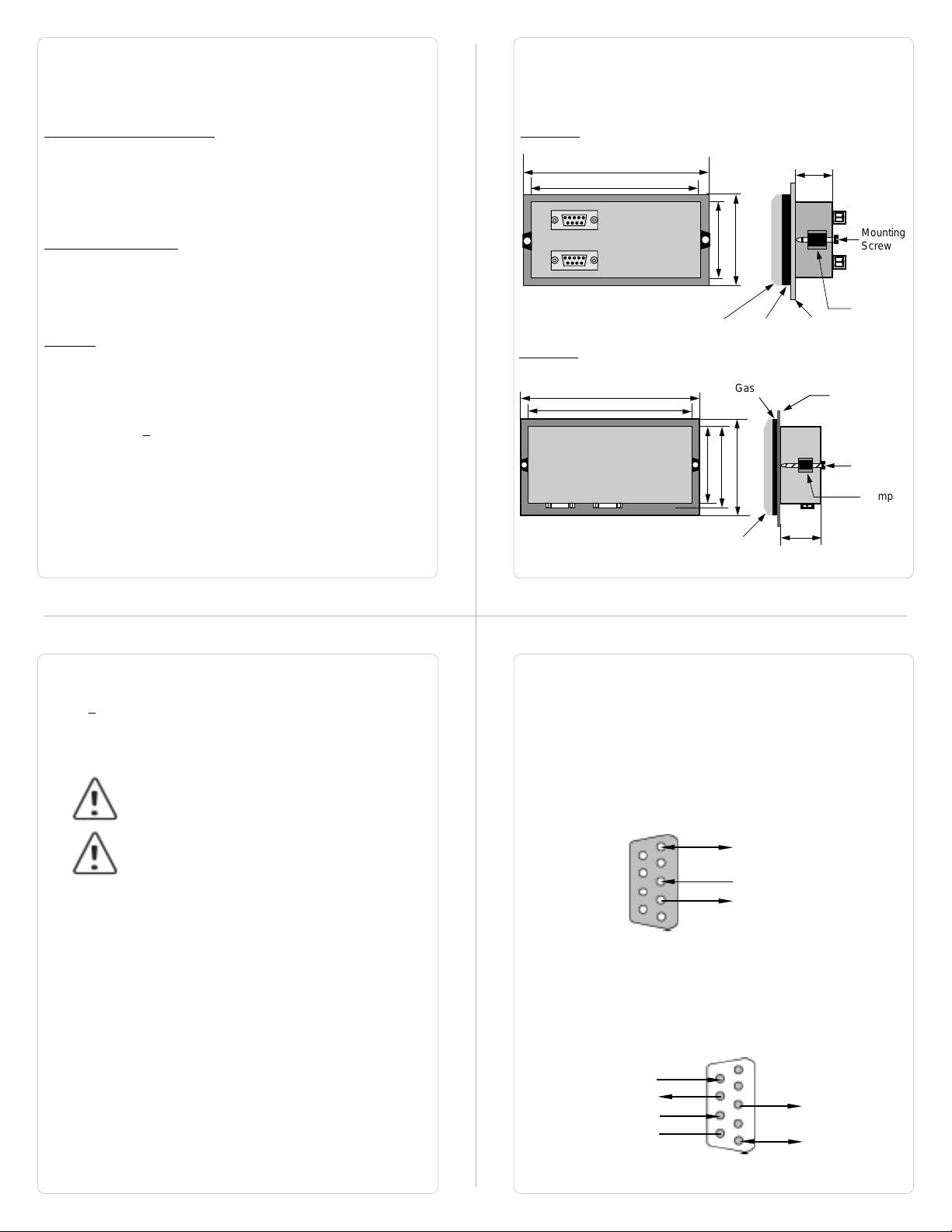
HG1X-252
Panel cutout: 92.00 x 45.00 (1/8 DIN size)
108.30
91.20
44.18
60.50
Bezel
Gasket
27.10
Mounting
Screw
Clamp
Panel
HG1X-452
Panel cutout: 162.00 x 79.00
75.20
78.50
Bezel
Gasket
101.30
Panel
Mounting
Screw
Clamp
36.8
182.50
160.70
2.3 Power Requirements
HG1X models are DC powered. The specified voltage range is
+5VDC + 5%. Make sure to check PLC power before connecting
cable to HG1X models.
Please follow the instructions given below while making connections
for HG1X models:
If wiring is to be exposed to lightening or surges,
use appropriate surge suppression devices.
Keep AC, high energy and rapidly switching DC
wiring separate from signal wires.
Each HG1X unit has two RS232 ports - a PLC Port and a Serial Port.
Description of each is given in following topics.
2.4 Serial Port
Serial port is used to download the firmware and / or application in to
the HG1X unit. HG1X also has serial printout capabilities. This port
can be attached to a computer/serial printer using the proper cable.
This port is always active. When HG1X is communicating with a PC
for programming, PLC operations are suspended. Pin description of
the Serial Port as seen on the HG1X unit is given below:
9
6
DB9 Female
5
1
Signal Ground
Receive / Data In (RS232C)
Transmit / Data Out (RS232C)
2.5 PLC Port
The cable connecting PLC to HG1X is attached to PLC Port. Different
cables are required for different PLCs / controllers. Cable details for
any particular PLC are given in the Operation Manual for that PLC.
Pin description of PLC Port for HG1X models is as given below:
+5 VDC from PLC
DIR / Open Collector Out
Receive / Data In (RS232C)
Reserved
6
9
1
5
Transmit / Data Out
(RS232C)
Signal Ground
DB9 Male
Page 5

Getting Started
In this chapter....
Introduction
Application - Tags, Screens, Keys and Tasks
PLC communication
3.1 Introduction
HG1X is an Operator Interface for PLCs. It communicates with a PLC
over its serial port to get the information required by the operator.
Information could be the value of a PLC register or the status of a
PLC coil. This information is displayed on the LCD display of HG1X. If
required, HG1X can also change the values of PLC registers / coils.
3.2 Application - Tags, Screens, Keys and Tasks
Microsoft Windows® based configuration software, WindMSG, helps
user to configure HG1X unit. ‘Configuration’ means making the HG1X
unit work as per the system requirements, Eg. HG1X can be
configured to be used with any PLC, display any register data,
perform any action using a key. The complete configuration for a unit
is termed as ‘Application’. Application comprises of Tag Data base,
Screens, Key Definitions, Alarms and Tasks.
Each register in the PLC memory has a unique address and can be
identified by giving a specific name to it. This information is stored as
Tag Data Base in HG1X. Any coil or register to be used in the
application must be first defined in the Tag data base.
LCD display on each unit displays the PLC data on a ‘Screen’.
Screen size varies with HG1X model. PLC data can be arranged on a
screen using different objects.
Operator can control the process by actually changing the value of
PLC registers. This is possible with the help of the keys. Different
tasks can be assigned to keys on the HG1X keypad.
Any register can be constantly monitored if alarms are defined for it.
When alarm condition is reached, the respective alarm is displayed
on the screen.
Page 6

Once the application is defined, firmware for the specific unit and
PLC is downloaded and then application is downloaded into the unit.
HG1X can now communicate with a PLC.
3.3 PLC communication
HG1X can communicate with any PLC without any change in the
hardware. To communicate with a PLC, HG1X needs:
1. Communication Driver for the PLC
2. HG1X - PLC communication cable
1. Communication Driver for the PLC:
Each PLC has a defined protocol for communicating with any
device. Communication Driver is downloaded in to HG1X
alongwith the firmware. Communication driver varies from
PLC to PLC. This driver enables HG1X to talk to a PLC.
2. HG1X - PLC Communication Cable:
Proper HG1X - PLC cable is required for error free
communication with any PLC.
Understanding HG1X Features
In this Chapter...
Screens
Properties of Screen
Screen Objects
Animation Properties
Alpha-Numeric Objects
Keys
Double Key Tasks
Tasks
Alarms
Consecutive
Discrete
Application Task-List
This chapter explains in detail all the features of HG1X. We
recommend that you study this chapter before attempting to configure
and use the HG1X.
4.1 Screens
Operator can view required information on the LCD display of HG1X
unit. This information can be arranged in such a way that the operator
can very easily interpret the information received. This can be done
by using various tools. These tools are the objects. Each screen has
some properties:
Properties of Screen:
1. Password:
Access levels can be achieved by introducing a password for a
screen. Password value can vary between 0 - 9999. Unless user
enters the correct password, the screen will not be displayed. Any
screen can be password protected.
2. Associated Screens:
Associated screen can be specially useful in cases where one or
more objects are common between different screens. The common
part is extracted from all the screens, placed in a new screen and this
new screen is associated with the other screens. Any screen can be
associated to another screen.
Advantages of associated screens:
1. Saves application memory by extracting common part
between different screens and forming a new associate
screen.
2. Saves time of the application programmer.
Please note:
- Only one screen can be associated to any screen.
- No data entry object can be placed in the screen to be
accociated.
Page 7

- No PLC tag embedding in the screen to be associated. To
embed a PLC tag, In Global Task-List the required PLC tag
should be copied to an internal tag. The internal tag should
be embedded in the screen to be associated.
3. Screen Keys or Local Keys:
HG1X keys have two types of definitions: Global and Local.
1. Global Definitions: Definitions remain same for all the
screens. If there is no local definition for a key for the
current screen, global definition for the key will be
executed.
2. Local Definitions: These definitions can vary with
screens. These definitions have priority over Global
definitions.
Please note that for a particular screen, a key can have local and
global definitions, local definition has priority over global and the
global definition task is not performed in this case.
Any task can also be performed by pressing two keys simultaneously.
The definition can be either local or global. The double keys function
can be very useful in HG1X models with less number of keys.
4. Screen Task-List
Tasks are operations performed by HG1X when a certain condition is
reached. Different tasks can be defined for different screens. Screen
Tasks can be assigned for three different conditions:
- Before showing
These tasks are performed before displaying a
particular screen on the display.
- While showing
Tasks are repeatedly performed while the screen is
displayed.
- After Hiding
Tasks are performed after another screen is called and
before displaying a new screen.
Example: Suppose Screen 1 is currently on the display
simultaneously performing ‘while showing’ task. Now PLC Tag calls
for Screen 2. Both the screens have all three types of tasks: Before
showing task, While showing task, After hiding task. Tasks will be
performed in following sequence:
1. After hiding task for screen 1 performed while clearing screen
no. 1.
2. Before showing task for screen 2 performed.
3. Screen 2 displayed.
4. While showing task list performed repeatedly.
5. When another screen is called after hiding task performed
while clearing screen 2.
Types of ScreenTasks:
1. Goto Screen
2. Goto Next Screen
3. Goto Previous Screen
4. Write Value to a Tag
5. Add a Constant Value to Tag
6. Subtract a Constant Value from Tag
7. Add Tag B to Tag A
8. Subtract Tag B from Tag A
9. Turn Bit On
10. Turn Bit Off
11. Copy Tag B to Tag A
12. Swap Tag A and Tag B
13. Print Data
14. Copy Tag to STR*
15. Copy Tag to LED
16. Delay
17. Wait till
* STR: Screen Triggering Register
1. Goto Screen:
Current Screen is replaced by the defined screen. This
command does not work when a PLC register is used as STR.
More information given in Application Task-List Section.
2. Goto Next Screen:
This task is useful when two screens are in succession.
Screen is changed to display the next screen.
If two screens
are not successive, there is a gap between two screens then
‘Screen not defined’ message will be displayed. This
message will stay on the screen till a valid screen is called.
This task does not work when a PLC tag is used as a STR.
3. Goto Previous Screen:
This task is useful when two screens are in succession.
Screen is changed to display the previous screen.
screens are not successive, there is a gap between two
screens then ‘Screen not defined’ message will be displayed.
This message will stay on the screen till a valid screen is
called.
Again this task does not work when a PLC tag is used
as a STR.
4. Write Value to a Tag:
A constant value can be downloaded to a tag using this task,
provided the tag is not a read-only tag.
5. Add a Constant Value to Tag:
A constant can be added to the current value of a tag using
this task.
6. Subtract a Constant Value from Tag:
This task is used to subtract a constant value from the current
value of a tag.
If two
7. Add Tag B to Tag A:*
Tag B can be added to tag A using this task. The result will be
stored in tag A.
8. Subtract Tag B from Tag A:*
Tag B is subtracted from tag A using this task. The result will
be stored in tag A.
9. Turn Bit On:
Any coil or bit can be turned on using this task. The bit/coil
should be a read-write coil.
10. Turn Bit Off:
Any coil or bit can be turned off using this task. The bit/coil
should be a read-write coil.
11. Copy Tag B to Tag A:*
Tag B can be copied to tag A using this task. The value of tag B
will be unchanged. Tag A will be same as tag B.
12. Swap Tag A and Tag B:*
Values of two tags can be swapped using this task. Tag A
value will be copied to tag B and tag B value will be copied to
tag A.
13. Print Data:
All the text data will be printed on the serial port.
Communication settings will be same as defined in ‘Prizm
Settings’ ‘Printer Port Options’ window. Graphical objects will
not be printed.
14. Copy Tag to STR:
A PLC tag can be copied to STR, Screen Triggering Register.
STR is a system register inside Prizm which decides the
screen to be displayed.
Page 8
15. Copy Tag to LED:
LED’s on the keypad of each HG1X can be turned on/off
depending on the value of a tag. The tag should be copied to
LED register and the LEDs will display the tag value.
16. Delay:
Any task can be delayed using this task. Tags will be updated
during this delay.. After the delay is completed the next task will
be performed.
17. Wait till:
This is a conditional delay. Next task will not be performed till
the specified condition is false.
* While defining double Tag operations, make sure both the tags
have same number of bytes. Else the task may lead to erroneous
results.
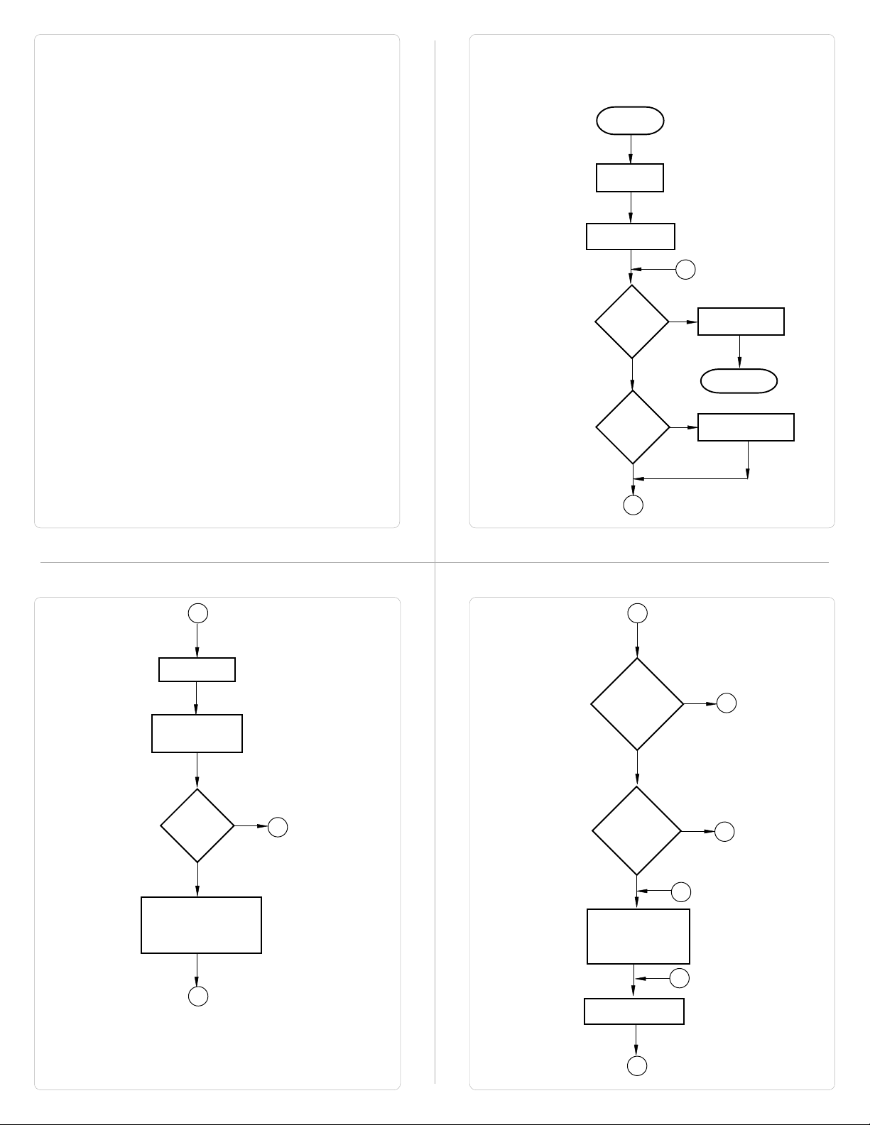
How HG1X works?
All the HG1X models follow a particular sequence for performing the
tasks defined by the user in the application. The sequence is as
shown below:
START
Power-up
Message
Power up Task
A
B
Global Task
Check Screen
Number
IBM
Comm
?
Y
PLC
Comm
Error
?
N
B
E
Password
Protected
Screen
?
Y
N
Complete IBM
Communication
Re-Start
Re-establish PLC
Y
Communication
N
D
Same
Screen
?
Perform After Hiding
Task for Previous
Screen
E
Y
N
C
Valid
Screen
password
?
Y
Perform Before
Showing Task List
for new Screen
Upload Tag Block
H
N
F
D
C
Page 9
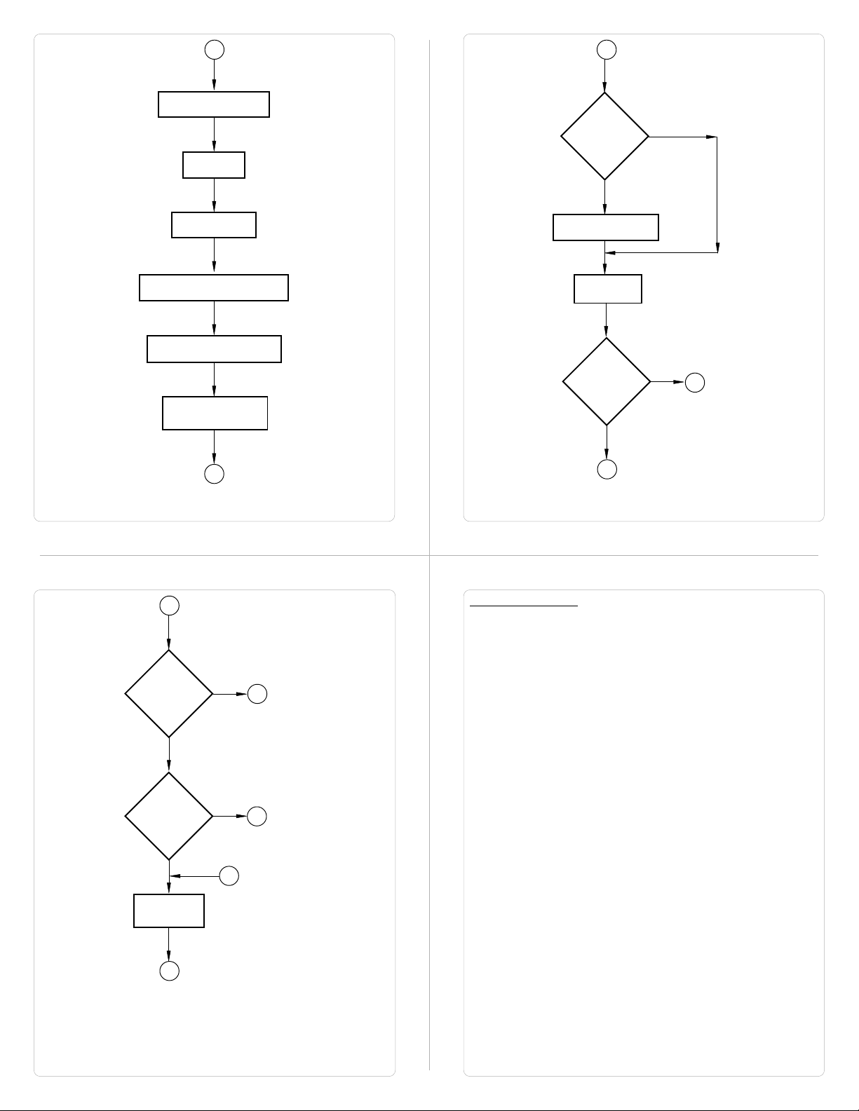
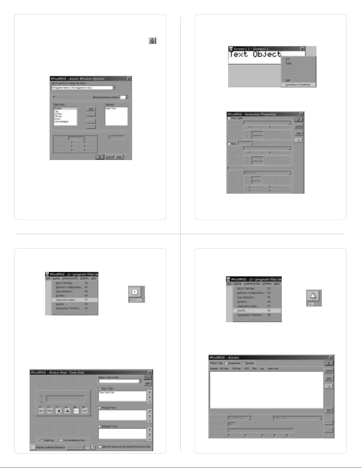
H
Upload Alarm Block
Serv Alarm
I
Same
key
Pressed
?
N
Y
Display Screen
Display Associated Screens
Serv While Showing Task
Check if same key
pressed
I
J
Password
Protected
Key ?
Y
N
G
Key Release task
Load new
keys
N
New
key
Pressed
?
Y
J
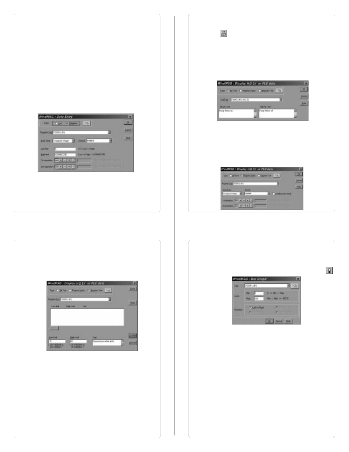
Animation Properties:
All the objects (except Register / Coil Data Entry Objects) have
Animation Properties. Animation Property is a conditional property of
an object which changes with the value of the Tag associated with it.
Animation properties are of three types: Show / Hide, Flashing and
Percent filling.
1. Show / Hide Animation: Object is displayed only when the
condition specified by the user is true.
2. Flashing Animation: An object is flashed when the condition
becomes true.
A
Valid Key
Password
?
Y
Serv Key
Press Task
A
Screen Objects have certain properties, referred as ‘Attributes’.
Attributes are useful for suggesting the importance of the particular
N
A
G
text object. Attributes for are:
- Flash
User can assign flashing to any text object*. An object can
flash at three different speeds: Slow, Medium and Fast. By
default no object is assigned flashing attribute. If flashing is
defined, slow flashing is selected by default.
objects (Coil and Register) do not have flash attribute.
* Data Entry
Page 10

Screen Objects can be further divided into:
1. Plain Text
2. Coil Data Entry
3. Register Data Entry
4. Display Coil Data
5. Display Register Data
6. Register Text
7. Error
8. Alarms
9. Bargraph
1. Plain Text:
Plain text object is useful for displaying any message for the
operator. Plain Text Objects do not depend on the PLC. Even
if the PLC is not connected, this object will be displayed.
2. Data Entry Objects:
Any register or coil from the PLC Memory, except Read-only
registers and coils, can be edited using the HG1X keypad.
Coil Data Entry:
Procedure to a edit coil is as follows:
1. Press a key with definition ‘Accept Data Entry‘ to initiate
data entry mode. Data entry mode is indicated by flashing
the complete data entry object.
2. Use keys with definition ‘Increase Digit by 1’ or Numeric
keys ‘0’ and ‘1’ to edit data.
3. Press key with definition ‘Accept Data Entry‘ to accept the
data entered. When a new application is created each
key is assigned a default definition by the software.
Default keys required for coil data entry are as shown in
Table 4.1.
Table 4.1
Model Initiate Edit Keys Accept
Data Entry Data Entry
F6
HG1X-252
HG1X-452 and
ENT
ENT ENT
F4
+/-
0
1
F6
ENT
Register Data Entry:
Procedure to a edit register is as follows:
1. Press key with definition ‘Accept Data Entry‘ to initiate data
entry mode. Data entry mode is indicated by flashing the last
digit of the register. Key with definition ‘Clear Data Entry’
clears the data. Key with definition ‘Cancel Data Entry’
cancels the data entered and exits data entry mode.
2. For models with numeric keypad, press key with definition
‘Sign (+/-) and 0’ to enter negative sign. Sign will be
automatically adjusted for the other models. For models
without numeric keypad, use keys with definition ‘Increase
Digit by 1’ and ‘Shift Value to Left’ else use Numeric keys ‘0’
through ‘9’ to edit register data.
3. Press key with definition ‘Accept Data Entry‘ to accept the
data entered. When a new application is created each key is
assigned a default definition by the software. Default register
data entry keys are as shown in Table 4.2.
Table 4.2
Model Initiate Edit Keys Accept
Data Entry Data Entry
HG1X-252
HG1X-452 through
F6
ENT
ENT
F4 F3
ESC
+/-
0
F5
CLR
9
4. Display Bit Text:
This object displays text depending on the bit status. Bit on and
Bit off text is defined by the user while writing the application.
5. Display Register Value:
This object displays the value of a register.
6. Display Register Text:
This object displays text depending value of a register. Text is
defined by the user while writing the application.
7. Error Field:
This object displays type of error occurred during PLC
communication.
8. Alarms:
This object displays the alarm text when the alarm occurs.
First triggered alarm is on top. Alarm condition for alarm should
be cleared. Each alarm has to be acknowledged. ‘Acknowledge
Alarm’ key acknowledges the alarm. The alarm text is cleared
when the alarm condition is cleared and the alarm is
acknowledged.
9. Bargraph:
Bargraphs are PLC register dependent objects which change
their bar height / width according to the PLC register. Bargraph
F6
ENT
ENT
does not have flash attribute but can be assigned ‘Show-Hide’
and ‘Flash’ animation.
Page 11

4.2 Keys
Keys are needed whenever the operator has to modify some PLC
data, acknowledge an alarm or take a control action. HG1X keypad
has the ability to perform the above mentioned as well as many more
tasks. User can define the task to be performed by each key.
Key Tasks are divided into following types depending upon the type
of key closure:
- Key Press Tasks
These tasks are performed at the instance of key closure.
- Key Pressed Tasks
These tasks are performed while a key is pressed and held
down.
- Key Release Tasks
These tasks are performed when a key is released.
Types of Tasks:
1. Goto Screen
2. Goto Next Screen
3. Goto Previous Screen
4. Write Value to a Tag
5. Add a Constant Value to Tag
6. Subtract a Constant Value from Tag
7. Add Tag B to Tag A
8. Subtract Tag B from Tag A
9. Turn Bit On
10. Turn Bit Off
11. Toggle Bit
12. Copy Tag B to Tag A
13. Swap Tag A and Tag B
14. Print Data
15. Copy Tag to STR
16. Copy Tag to LED
17. Delay
18. Wait till
19. Key Specific Tasks
1. Goto Screen:
Current Screen is replaced by the defined screen. This
command does not work when a PLC register is used as STR.
More information given in Application Task-List Section.
2. Goto Next Screen:
This task is useful when two screens are in succession.
Screen is changed to display the next screen.
If two screens
are not successive, there is a gap between two screens then
‘Screen not defined’ message will be displayed. This
message will stay on the screen till a valid screen is called.
This task does not work when a PLC tag is used as a STR.
3. Goto Previous Screen:
This task is useful when two screens are in succession.
Screen is changed to display the previous screen.
If two
screens are not successive, there is a gap between two
screens then ‘Screen not defined’ message will be displayed.
This message will stay on the screen till a valid screen is
called.
This task does not work when a PLC tag is used as a
STR.
4. Write Value to a Tag:
A constant value can be downloaded to a tag using this task,
provided the tag is not a read-only tag.
5. Add a Constant Value to Tag:
A constant can be added to the current value of a tag using
this task.
6. Subtract a Constant Value from Tag:
This task is used to subtract a constant value from the current
value of a tag.
7. Add Tag B to Tag A:*
Tag B can be added to tag A using this task. The result will be
stored in tag A.
8. Subtract Tag B from Tag A:*
Tag B is subtracted from tag A using this task. The result will
be stored in tag A.
9. Turn Bit On:
Any coil or bit can be turned on using this task. The bit/coil
should be a read-write coil.
10. Turn Bit Off:
Any coil or bit can be turned off using this task. The bit/coil
should be a read-write coil.
11. Toggle Bit:
Any bit can be toggled using this task. The bit / coil will be
toggled each time the key is pressed.
12. Copy Tag B to Tag A:*
Tag B can be copied to tag A using this task. The value of tag
B will be unchanged. Tag A will be same as tag B.
13. Swap Tag B to Tag A:*
Tag A and Tag B values can be swapped using this task.
14. Print Data:
Text data on the particular screen will be printed.
15. Copy Tag to STR:
Any specified task will be copied to STR. This STR decides the
screen to be displayed.
16. Copy Tag to LED:
LEDs of the HG1X can be used to reflect the value of a tag. The
tag should be copied to LED register for such functionality.
17. Delay:
An unconditional delay can be added to the task list. All the tasks
after this task are delayed by the specified time.
18. Wait till:
All the tasks after this task are not performed till the condition
specified by this task does not become true.
19. Keys Specific Tasks:
Apart from the above mentioned tasks each key can be
assigned a task which can be common to all the tags.
Types of key specific tasks:
1. Clear Data Entry
Clears Data after data entry is initiated.
2. Cancel Data Entry
Cancels the data entered and restores previous data.
3. Accept Data Entry
Initiates data entry and accepts data entered.
4. Switch to next Data Entry
Next data entry is selected.
5. Increase Value by 1
Value of a tag is increased by 1.
6. Decrease Value by 1
Value of a tag is decreased by 1.
7. Increase Digit by 1
Value of a single digit of a tag is increased by 1.
8. Decrease Digit by 1
Value of a single digit of a tag is decreased by 1.
9. Shift Value to Left
Value is shifted to left.
10. Move Cursor to Left
Cursor is moved to left to edit next digit.
11. Move Cursor to Right
Cursor is moved to right to edit next digit.
Page 12

12. Sign Key (+/-)
Used for signed data entry.
13. Sign Key (+/-) and 0
Single key used as a sign key as well as numeric key 0. If
this key is pressed immediately after data entry is initiated,
key is taken as sign key else it is taken as ‘0’ key.
14. Numeric Key 0
Enters a ‘0’ after data entry is initiated.
15. Numeric Key 1
Enters a ‘1’ after data entry is initiated.
16. Numeric Key 2
Enters a ‘2’ after data entry is initiated.
17. Numeric Key 3
Enters a ‘3’ after data entry is initiated.
18. Numeric Key 4
Enters a ‘4’ after data entry is initiated.
19. Numeric Key 5
Enters a ‘5’ after data entry is initiated.
20. Numeric Key 6
Enters a ‘6’ after data entry is initiated.
21. Numeric Key 7
Enters a ‘7’ after data entry is initiated.
22. Numeric Key 8
Enters a ‘8’ after data entry is initiated.
23. Numeric Key 9
Enters a ‘9’ after data entry is initiated.
24. Numeric Key A
Enters a ‘A’ after data entry is initiated.
25. Numeric Key B
Enters a ‘B’ after data entry is initiated.
26. Numeric Key C
Enters a ‘C’ after data entry is initiated.
27. Numeric Key D
Enters a ‘D’ after data entry is initiated.
28. Numeric Key E
Enters a ‘E’ after data entry is initiated.
29. Numeric Key F
Enters a ‘F’ after data entry is initiated.
30. Edit Bit On
A coil is turned on after data entry is initiated.
31. Edit Bit Off
A coil is turned off after data entry is initiated.
32. Acknowledge Alarm
Active alarm is acknowledged using this key.
33. Next Alarm
Next alarm from the container is displayed.
34. Previous Alarm
Previous alarm from the container is displayed.
* While defining double Tag operations, make sure both the tags
have same number of bytes. Else the task may lead to erroneous
results.
4.3 Alarms
Any tag can be continuously monitored by defining alarms for each bit
of that tag. To display an alarm on the screen as soon as it is
triggered, alarm object has to be placed on the screen. If the value of
the particular tag becomes nonzero, alarm is displayed in the alarm
object. An alarm is triggered for each bit in a tag. Total 256 alarms
can be defined in HG1X. HG1X stores the alarm information in an
alarm container. Maximum 64 alarms can be stored in the container.
First triggered alarm is on the top of the container. New alarm is
added from the bottom. Operator has to acknowledge each alarm by
using any key with definition ‘Acknowledge Alarm’. When alarm
condition is cleared and the alarm is acknowledged, the alarm is
deleted from the container. Alarm can also be printed on the serial
port. Printing is performed as soon as the alarm is triggered.
Two types of alarms can be defined in HG1X:
1. Consecutive Alarms
2. Discrete Alarms
1. Consecutive Alarms:
Consecutive alarms can be useful when user wants to monitor 16
consecutive tags. All the 16 consecutive tags should be defined in the
tag database. An alarm cab be defined for each bit. HG1X uploads all
16 tags in a single block. When any bit of 16 tags is found to be on
(‘1’) corresponding alarm is triggered. Triggered alarm is displayed in
the alarm object. Each alarm has to be acknowledged. User should
define a key to acknowledge alarms. User can also scroll through the
table of alarms using keys defined as ‘Next Alarm’ and ‘Previous
Alarm’. Acknowledged and inactive alarm is deleted from the
container. New alarm is added from the bottom of the container.
2. Discrete Alarms:
Discrete alarms can be useful when user wants to monitor tags which
are not in a sequence, discrete. An alarm is defined for each bit of
tag. When any bit of any tags is found to be on (‘1’) corresponding
alarm is triggered. Triggered alarm is displayed in the alarm object.
User should define a key to acknowledge alarms. User can also scroll
through the table of alarms using keys defined as ‘Next Alarm’ and
‘Previous Alarm’. Acknowledged and inactive alarm is deleted from
the container. New alarm is added from the bottom of the container.
Page 13

4.4 Application Task-List
Application task-list allows user to define tasks to be performed at
power-on or while application is running i.e. Global Task.
Application task-lists are of two types:
1. Power-on tasks:
Power-on tasks are performed after HG1X unit is powered on.
These tasks are like a boot sequence for HG1X which are
performed only once. Using these tasks user can initialize some
registers, goto a particular screen after power up etc.
Please
note that user MUST define ‘Goto Screen’ Task in Power-On
task list.
2. Global tasks:
Global tasks are performed regularly till the application is in
progress. These tasks are useful when the user wants to
perform some tasks repeatedly. In case the PLC is not connected
then PLC related tasks will not be performed.
The tasks supported are as follows:
1. Goto Screen
2. Goto next screen
3. Goto previous screen
4. Write value to tag
5. Add constant value to tag
6. Subtract constant value from tag
7. Add Tag B to Tag A
8. Subtract Tag B from Tag A
9. Turn bit on
10. Turn bit off
11. Toggle bit
12. Copy Tag B to Tag A
13. Swap Tag A and Tag B
14. Print Data
15. Copy Tag to STR
16. Copy Tag to LED
16. Delay
17. Wait till
1. Goto Screen:
Current Screen is replaced by the defined screen. This
command does not work when a PLC register is used as STR.
More information given in Application Task-List Section.
2. Goto Next Screen:
This task is useful when two screens are in succession.
Screen is changed to display the next screen.
If two screens
are not successive, there is a gap between two screens then
‘Screen not defined’ message will be displayed. This
message will stay on the screen till a valid screen is called.
This task does not work when a PLC tag is used as a STR.
3. Goto Previous Screen:
This task is useful when two screens are in succession.
Screen is changed to display the previous screen.
If two
screens are not successive, there is a gap between two
screens then ‘Screen not defined’ message will be displayed.
This message will stay on the screen till a valid screen is
called.
This task does not work when a PLC tag is used as a
STR.
4. Write Value to a Tag:
A constant value can be downloaded to a tag using this task,
provided the tag is not a read-only tag.
5. Add a Constant Value to Tag:
A constant can be added to the current value of a tag using
this task.
6. Subtract a Constant Value from Tag:
This task is used to subtract a constant value from the current
value of a tag.
7. Add Tag B to Tag A:*
Tag B can be added to tag A using this task. The result will be
stored in tag A.
8. Subtract Tag B from Tag A:*
Tag B is subtracted from tag A using this task. The result will
be stored in tag A.
9. Turn Bit On:
Any coil or bit can be turned on using this task. The bit/coil
should be a read-write coil.
10. Turn Bit Off:
Any coil or bit can be turned off using this task. The bit/coil
should be a read-write coil.
11. Toggle Bit:
Any bit can be toggled using this task. The bit / coil will be
toggled each time the key is pressed.
12. Copy Tag B to Tag A:*
Tag B can be copied to tag A using this task. The value of tag B
will be unchanged. Tag A will be same as tag B.
13. Swap Tag B to Tag A:*
Tag A and Tag B values can be swapped using this task.
14. Print Data:
Text data on the particular screen will be printed.
15. Copy Tag to STR:
Any specified task will be copied to STR. This STR decides the
screen to be displayed.
16. Copy Tag to LED:
LEDs of the HG1X can be used to reflect the value of a tag. The
tag should be copied to LED register for such functionality.
17. Delay:
An unconditional delay can be added to the task list. All the tasks
after this task are delayed by the specified time.
18. Wait till:
All the tasks after this task are not performed till the condition
specified by this task does not become true.
* While defining double Tag operations, make sure both the tags
have same number of bytes. Else the task may lead to erroneous
results.
Page 14

Configuration Software
In this Chapter...
Introduction to HG1X Software
Installing HG1X Software
HG1X Software - Basics
Create a new Application
Setup Node
Create Tag Data Base
Create Screens
Define Keys
Define Alarms
Application Task List
Download Application
5.1 Introduction
WindMSG is Windows based software to configure the HG1X Series
Interfaces by IDEC Corporation. WindMSG's tools and easy
approach can help you create your applications quickly and easily. By
using some of WindMSG's new features, you can be more effective in
what you need. Whether you need a small application to monitor data
or a bigger application for both monitoring and changing data in your
PLC, WindMSG has it all. With WindMSG you can get started quickly
to use your HG1X Interfaces.
Developing your applications for any HG1X Series is easy using
WindMSG. The common functionality found among many Windows
applications can also be found here and will allow you to quickly
adapt to WindMSG. Once you are familiar with the many visual clues
in WindMSG, creating an application will be a breeze. The idea
behind designing WindMSG and the HG1X is to allow you to get
where you want to... FAST!
You can use WindMSG to configure any HG1X model, to work with
ANY of the drivers supported. WindMSG currently supports over 25
PLCs and the following list of HG1X Models:
HG1X Series HG1X-252, HG1X-452
HG1X communicates with a PLC only after downloading correct
driver and application into the unit. HG1X user should follow the
given procedure to configure and use HG1X:
1. Create an application for required PLC.
2. Connect IBM cable.
3. Download Firmware i.e. driver for the PLC. HG1X models
cannot communicate with PLC till the required driver is
downloaded.
4. Download application.
5. Now connect the PLC to the unit using PLC cable.
5.2 Installing WindMSG Software
System requirements for installing WindMSG on your PC:
Windows Version : Microsoft Windows 95 or higher
Processor : PENTIUM or higher
Hard disk Space : 5 MB or more
Serial Mouse : Required
RAM : 16 MB or more
Display resolution : 640 x 480 (VGA) or better
Display colors : 16 colors or more
To install WindMSG software:
1. Open Microsoft Windows. The Start program task button is
located at the bottom left portion of your screen.
2. Place the installation CD into your PC’s CD drive.
3. Select Run, and a pop-up window appears. Type the path and
file name for installing setup (D:\SETUP.EXE).Press OK. Follow
the instructions given in the setup software.
Page 15

5.3 WindMSG Software
HG1X unit has to be configured before its use in any system.
Complete configuration consists of defining:
- HG1X Settings
- PLC node
- Tag Database
- Screens and / or Screens Task-List.
- Keys
- Alarms
- Global and Power-on Task list
The complete configuration is stored as an Application. This
application is downloaded in HG1X.
1. HG1X Settings:
HG1X Settings define following properties of HG1X:
a. Hardware Settings
- Application Memory
Use this if only you have purchased a nonstandard
unit with a different memory option.
b. Keypad options
- Keypad Queue Size
If task for a key is in progress and another key is
pressed, then the second key (latest pressed) is
stored in a Key Queue. User can change the queue
size using this option.
- Queue full options
User has a choice to select what should be done if
the queue is full and another key is pressed. Either
the first or the last key pressed can be ignored.
c. Printer Port Options
HG1X has a Serial Printout Facility. User should connect
Serial Printer cable to the Serial Port of the HG1X.
Communication parameters for serial printing can be changed
using this option.
Please note that this does not affect PC to
unit communication while downloading firmware or
application.
- Baud Rate
Baud Rates available are 300, 600, 1200, 2400,
9600, 19200.
- Number Of Bits
Data bits can either be 7 or 8.
- Parity
Parity options are Odd, Even, None.
- Number of Columns
User can select the column size i.e. length of a line to
be printed. After the specified number of characters,
HG1X sends a terminating character.
- Terminating Character
Options for terminating character are None, CR, LF,
CR+LF.
2. HG1X Network Configuration:
This setting selects the PLC Model, PLC type, Node number in a
system. User can also connect multiple PLCs of the same type
(protocol) to a single HG1X. Each PLC must have unique identification number which is termed as NODE ID.
3. HG1X Tags:
Each register in the PLC memory has a unique address and can be
identified by giving a specific name to it. This information is stored as
Tag Data Base in WindMSG. Any coil or register to be used in the
application must be first defined in the Tag data base.
4. Screens:
Operator views the PLC data on the screen of the HG1X models.
Tasks can be defined for a screen. Also, the action for keys when a
screen is acting can be defined.
5. HG1X Global Key’s Task-List:
All the keys on the HG1X models can have user selectable
definitions. Three types of tasks can be defined for each key: ‘Press’
Task, ‘Pressed’ Task, ‘Released’ Task. Two keys can also be defined
for performing Tasks. Each key single or double can have password.
6. HG1X Alarms:
Alarms can be defined in the Alarms Window. Alarms are defined on
a single bit of any one word tag. All the tags must be defined before
defining the Alarms. Alarms can be set on two types of Tags:
Consecutive and Discrete. In consecutive type, HG1X will fetch 16
words from the PLC beginning with the defined tag. Each bit in each
of these 16 words will be an alarm bit. In discrete type tags need not
be consecutive. Again, in this type each bit of each tag is an alarm
bit.
7. HG1X Application Task-List
Application Task List is of two types: Power-on Task-List and Global
Task-List. Power-On Task-List is performed only once after the unit is
powered on. Global Task-List is performed till the unit and PLC are
communicating.
Run WindMSG.exe. Following splash screen will be displayed.
Main window will be displayed after the splash screen. Main window
consists of two main parts: Menu Bar and the Tool Station.
Menu bar operates in the normal manner.
Click with mouse or use keys in combination
with ALT key just like any other standard Windows based software.
Tool-Station consists of icons. When mouse points to any icon, a
tool-tip is displayed. Click on the icon to select the particular menu.
Page 16

File
Menu
Define
Menu
File
Menu handles the file related functions.
N
ew
- Creates a new application.
O
pen
- Opens a saved application.
Clos
e
- Closes currently open application.
S
ave
- Saves currently open application.
Save as
I
nformation
Exit
- Saves the current application with a different name.
- Application related information can be stored here.
User can enter his comments here.
- Exits WindMSG Software.
This menu actually defines the application. In the main window of
WindMSG software, bottom line of the icons is dedicated for this
menu.
H
G1X Settings
N
etwork Configuration
T
ag DataBase
Screens
Application Keys
Alarms
- Defines alarms in the application.
Application Task-List
- Defines HG1X settings.
change HG1X Settings only if he has
bought a nonstandard unit.
User should
- Defines PLC node, node ID etc.
- Defines tag to be used in the application.
- Defines screens.
- Defines application keys.
- Defines Power-on and Global Task-list.
Communicate
Communicate
Menu
Menu Downloads / uploads application to / from HG1X.
Communication Port
D
ownload
U
pload
- Downloads Application to HG1X.
- Uploads Application from HG1X.
- Sets COM port for communicating with
HG1X.
Utilities
Utilities
informs the user about the memory used for the application.
A
dd or Remove PLCs -
W
indMSG Memory Configuration -
Help
I
ndex -
A
bout WindMSG -
Menu
Menu is basically useful for adding / removing PLCs. It also
Adds / removes PLCs to /
from the Selected PLCs list.
Displays statistics of the
Memory used by the current
application.
Help
Menu
Menu, as the name suggests, offers help for the user.
Lists all the Help topics
Displays the software
version number.
Page 17

5.4 Creating new Application
1. Select
New
Application
from
button.
File
menu or click on the
OR
New
3. Select
or click on the
HG1X Settings
HG1X Settings
from
Define
menu or Press F3 key
button.
OR
2. In the dialog presented, select the HG1X Model and press
5.5 Setup Network / Node
OK
.
4. In HG1X Settings dialog box, select Application memory,
Key Queue Size, Serial printout options. Press OK to
accept the selections made.
5.6 Create Tag Database
1. Select
2. In Network Configuration dialog box, Press
Network Configuration
F4
key or click on the
button. Now select PLC and PLC Model. Assign a Node
Address for the node Press OK to accept the selections
made. If another node has to be added repeat above steps
else press
Close
Network Configuration
from
OR
Define
menu or Press
button.
Add a Node
1. Select
2. In Tags dialog box select the Node, Tag type, Register,
Tag Database..
or click on the
enter Tag name and finally select number of bytes for the
Tag. Press
tags press
Add
Close
from
Define
Tags
button.
to accept the Tag. After adding all the
button.
menu or Press F5 key
OR
Page 18

5.7 Create Screens
1. Select
2. In
Screens..
click on the
Screens
New Screen
Screen Name, Password. Screen Name and Screen
description information is for programmers reference only.
This information is NOT displayed anywhere on the actual
HG1X Screen. Associated Screen option is available only
when some screens have already been defined. Click
to enter the
Screen Editor
from
Define
menu or Press F6 key or
button.
OR
dialog box, enter the Screen number,
.
OK
3. In the
Screen Keys and Screen Task-List . To place an object
click on the respective button in
will take the shape of the object. Click the mouse at the
required location on the screen to place the object. All the
tag dependent objects will allow user to access the Tag
data base from their dialog box. Clicking on the
button or another object button deselects the object
selected. Standard Windows operations like Copy, Cut,
Paste Objects, Redo, Undo are available in
Screens can also be duplicated using the duplicate button.
To exit from the
of
Screen
explained in detail.
Screen Editor
Window. In the following points Screen is
user can define Screen Objects,
Objects
window. Pointer
Screen Editor
, click on the
Selector
Tools
Close
window.
button
4. How to define Text Object:
Click on the
pointer will change. Now place the mouse pointer at
desired location and mark the area of text object while
holding the left mouse button. A block cursor will blink at
the location inside the text outline. Now enter text. Last
character will be overwritten If INSERT Mode (Computer
Keyboard) is disabled, else new character will not be
accepted.
Text
button . The shape of the mouse
5. How to define Coil Data Entry object:
Click on the
change to the tool shape. Now place the mouse pointer at
desired location and click the left mouse button. The data
entry dialog box will appear. This box will allow user to
select between Coil and Register Data entry. If Coil data
entry is selected fields to be completed are Coil Tag and on
/ off text.
Data Entry
button . The mouse pointer will
Page 19
6. How to define Register Data Entry Object:
To edit a register in the PLC, select
the Data entry dialog box. Register Data Entry dialog box
allows user to select the tag, Data type, data format, low
limit, high limit, Math -1st and 2nd operation. In tag
selection window, there is the list of Tags available data
can be written. You can select the one you want from the
list. The list will NOT display any read only registers which
can not be modified. Data entered can be limited by
assigning Low and High limit for the data entry. Data can
be entered in various types viz., Unsigned Integer, Signed
Integer, Hexadecimal, BCD, Binary (1 word), Float. Data
format can also be selected by the user. Low and High
limits restrict the data that can be entered in the register.
Two mathematical calculations can be performed on the
data be entered.
Register Data Entry
in
7. How to define Display HG1X / PLC Data object:
This object can be used to view HG1X / PLC data. To place
an embedding object click on ‘Display HG1X / PLC
Data’ Tool. In the dialog box user can select either Bit Text
or Register Value or Register Text. Bit Text displays text
depending on the state of coil or bit. Register Value
displays the actual value of the register. Register Text
displays text depending on the value of a register. To add
Bit Text object, select Bit Text in the Display HG1X or
PLC Data dialog box. In the window, user can enter text to
be displayed depending on the state of the Coil.
To display a register value, select Register Value type in
Display HG1X or PLC Data window. The window will now
change to display Register options. Select the register to be
displayed. Select the Data type and Format to display the
register. Leading Zero Blank option decides whether zeros
preceding the value will be displayed or not. If this option
is enabled then register value will be displayed without
Leading Zeros.
Register Text Object is value dependent text object. User
can define different text strings for different limits of register
values. When the limit is crossed the text changes. First
select the register from the Tags list. Now enter low limit,
high limit and text for that range. Click Accept button to
accept the entered data. Now click Add to enter new limits
and corresponding text.
10. How to define Bargraph object:
Bargraph is a graphical representation of the value of any
register. Bargraph is available in all the HG1X models. User
can also view the bargraph of a particular range of register
value. To place a bargraph click on the Bargraph button
.
Bargraph can be drawn for a specific range of the register
value. The maximm range is 0 to 65535.
Page 20
11. How to define Alarm object:
Alarm object displays alarm immediately after any alarm is
triggered. Alarm text is defined in the
To place an Alarm object, click on the
Alarms object can be edited by double clicking on the
object placed on the screen.
enable user to select the fields to be displayed in an
Alarms
be varied.
object. Sequence and length of each field can also
Alarms
dialog box.
Alarms
button .
Alarms Dialog box
will
14. To assign
the object with the mouse. Place the mouse on the
selected object and click with the right mouse button. From
the menu box presented select
option.
Flash
or
Scroll Animation
to any object, select
Animation Properties
5.8 Define Keys
1. To define Global Keys click on
Define
menu or press F7 or click on Global Keys Button.
Application Keys
from
15. In the
5.9 Define Alarms
1. Click on
Animation Properties
appropriate animation. Only Basic Graphical objects can
have Percent filling animation.
Alarms
Alarms Button to define Alarms.
from
dialog box select the
Define
menu or press F8 or click on
2. In
tasks to keys protect keys by assigning password. All the
keys on the HG1X keypad are redefinable. Most of HG1X
models have default definitions to keys.
Entry objects may not function properly if the required tasks
are not assigned to keys.
two keys. The task will be performed only when the two
keys are pressed simultaneously. Click on
close
Global Keys’ Task-Lists
Tasks can also be assigned to
Global Keys’ Task-Lists
OR
dialog box, user can assign
Please note Data
Close
dialog box.
button to
2. In
For
define alarms. Select group of alarms. Enter alarm number
and alarm text. Click relevant options for the particular
alarm. Click
Alarms
dialog box click either
Consecutive
Accept
OR
Consecutive
type select the first tag. Click
to accept the alarm.
or
Discrete
Add
.
to
Page 21

5.10 Application Task-List
1. Click on
F9 or click Application Task-List Button to define
Application Task-List.
Application Task-List
from
OR
Define
menu or press
5.11 Save Application
1. To save the application, click on
press F2.
Save
OR
from
File
menu or
2. In
2. Select the appropriate COM port and click OK to set the
Application Task-List
power-on tasks. Power-on task-List is like a boot sequence
for HG1X. User must direct HG1X to display a particular
screen in Power-on Task-List. Global task-list depends on
the system requirements. User can either use keys to
switch between screens or use a PLC tag to trigger
different screens.
COM port.
user can define global and
2. Default location to save application is ..\WindMSG\Result\
5.12 Download Application to HG1X
1. Click on
directory. Extension should be *.PZM.
to set the COM port.
Communication Port
from
Communicate
menu
3. Click on
4.
5. After Application Download is successfully completed, click
download application into the HG1X unit.
In Download
on
Download..
Close
to exit Download dialog box.
from
dialog box click on
Communicate
OR
Application
menu to
. Click OK.
Page 22

How Do I?
In this Chapter...
6.1 Frequently asked questions
This chapter answers the questions user normally asks.
1. How can I read PLC data?
To read any PLC data, the required tag should be defined in
the Tag Database. In a screen the tag should be embedded
in the required format.
2. Can I edit PLC data? How?
Any PLC register / coil can be edited except for ‘Read only’
registers / coils. Generally System registers and Input coils
are ‘Read only’. ‘Read only’ registers / coils vary from PLC to
PLC. Please refer to PLC manual for details. To edit any PLC
data define the tag in Tag Database. Place a ‘Data Entry’
object in a screen. Make sure to define the required keys.
Register and Coil data entry key definitions are given in
Table 4.1 and Table 4.2.
3. Can I keep a record of the Process data?
HG1X models can send screen data (Alphanumeric data
only) on its serial port. This output can be given to a serial
printer and a record of events can be achieved. A screen with
‘Print Data’ task can print all the alphanumeric objects.
4. Can I change screens using PLC logic?
Any PLC tag can be copied to STR, a system register internal
to HG1X, and HG1X will display the corresponding screen.
User must define the task ‘Copy tag to STR’ in Global
Application Task-List. Make sure to define screens to all the
possible values of the tag to avoid ‘Screen not defined’
message. Please note that the ‘Goto screen’, ‘Goto next
screen’ and ‘Goto previous screen’ tasks will not work in this
case. To change the screen the value of the PLC ta should
be changed.
Frequently asked questions
5. Can I perform any task continuously?
To perform any task continuously define the task in Global
Application Task-List. This task will be performed till the unit
is powered.
6. How can I ‘Hold’ any Bit on or off using a key?
To hold a bit on using a key, define ‘Turn bit on’ task in ‘Key
press task-list’ and ‘Turn bit off’ task in ‘Release key task-list’
for the same key.
7. How do I keep any screen or any key locked?
Any screen or a key can be kept secret using the ‘Password’
feature of HG1X. Password protected screen will not be
displayed till the user enters the correct password. Similarly
task for password protected key will not be performed till user
enters the correct password.
8. Can I assign scaling factor for any tag?
Value of any tag can be converted in to the required format
by performing ‘Math Operations’ on it. This DOES not change
the value of the actual tag. ‘Math Operations’ can be
performed in ‘Display HG1X / PLC Data’ objects. Data to be
written to a tag can also be manipulated by assigning ‘Math
Operations’ in ‘Data Entry’ object.
9. Can I limit the data to be entered in a tag?
Data entered in any register tag can have high and low limits.
This keeps a check on the register limits.
Refer to ‘Configuration software’ section for detailed information on
how to define an application.
Page 23
Appendix A
WindMSG Tutorials
Example to create Application for HG1X
Tutorial 1: Create an Application for HG1X
Model
We will create an application for HG1X-252 unit with internal tags
only. Follow the following steps:
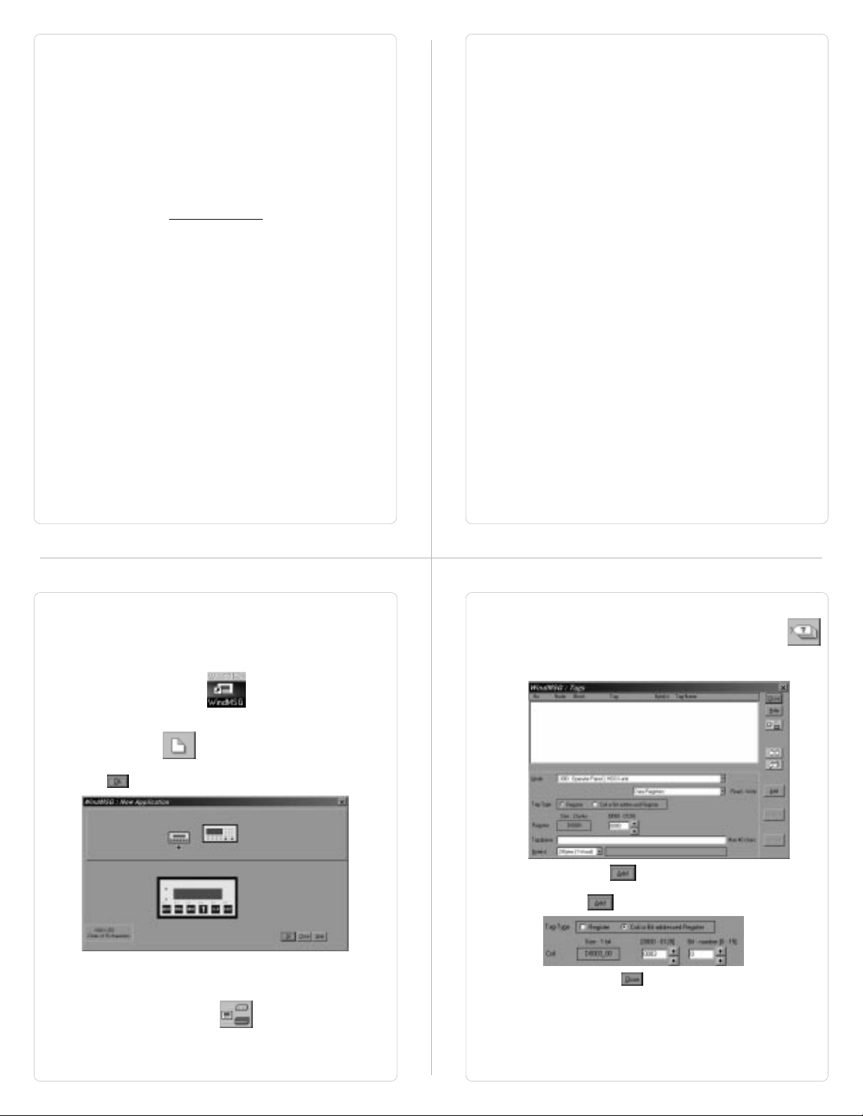
1. Run WINDMSG.EXE.
2. After the main window is displayed, click on the New
Application icon
3. From the New application dialog box, select required unit and
click to accept the selection made.
4. As said earlier, this application is being developed with
internal tags only, hence we will not be adding any PLC in the
network. If user wants to add PLC in the network, click on the
Network Configuration icon
5. Now we have to define tags required for the application. It is a
good practice to define the tags before developing the
application. To define Tags click on Tag Database icon.
Following dialog box will be displayed. Select required
register type and register address, enter your name for the
tag.
Click on Add button to accept the tag defined. To define
a coil, change the selection Tag-type. Enter coil number, tag
name and click to accept the tag entry.
Click on Close button to close the Tag Database
window.
Page 24
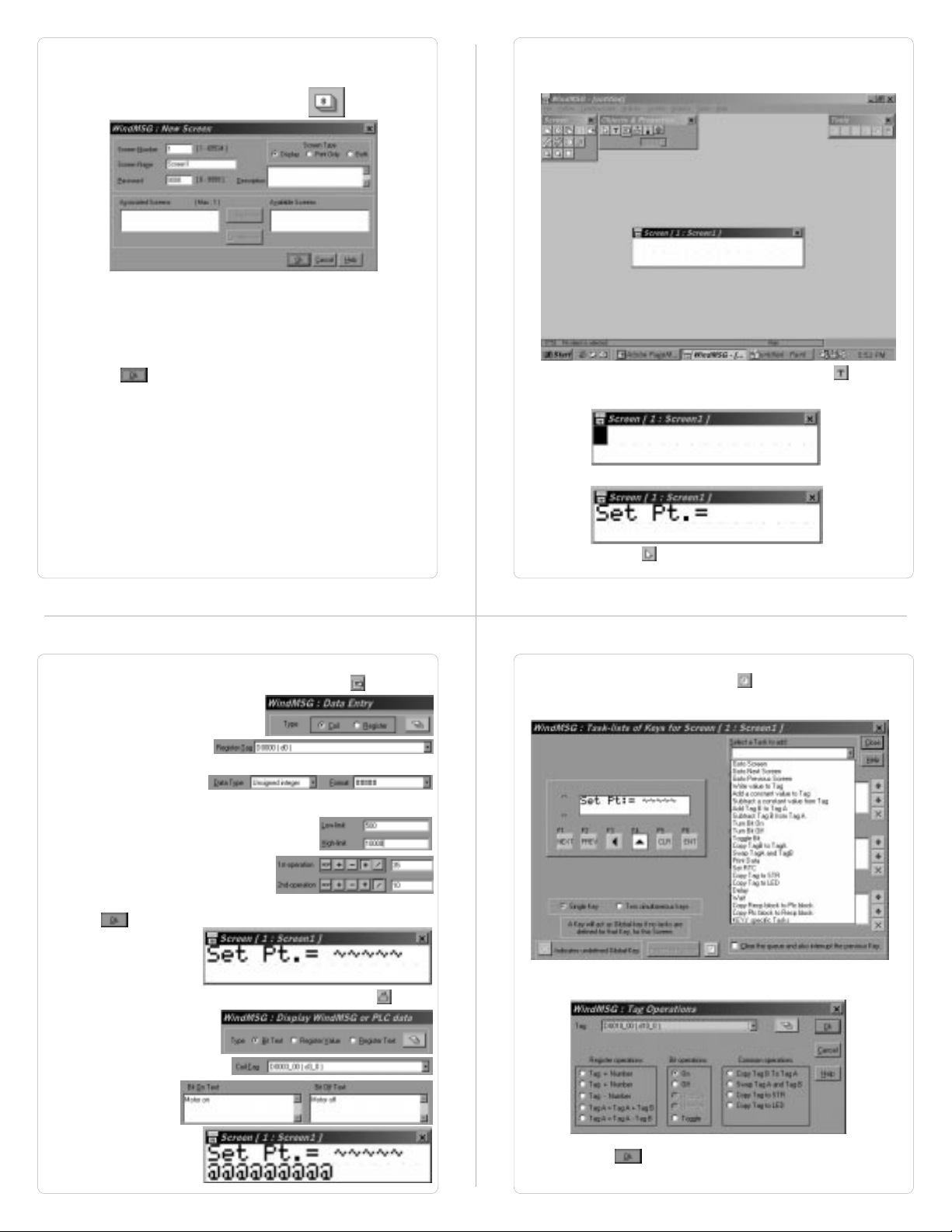
6. Now we will define Screens. Screens form the most important
part of any application as it displays the information required
by the operator. HG1X has various objects to make a screen
operator-friendly. Click on Screens icon to define
screens.
In the dialog box, enter the screen number, name and
password. Also select screen type.
Display: Screen will be displayed and will perform all tasks.
Print Only: Screen will only be printed after it is triggered.
Both: Screen will be displayed and printed after it is triggered.
Click to create a new screen.
Following Screens window will now appear on the monitor.
This window defines all Screen objects, Screen task-list and
Screen keys.
Now we have to place plain text objec, click on text icon . Place
the object at required place on the screen and click. A blinking blob
will appear.
Enter Text.
Now we have to place a register data entry with math and limits. To
place the object on the screen, click on data entry icon .
Select Type ‘Register’.
Select tag from the tag list.
Select data type and format.
We select ‘Unsigned Integer’
and 5 digit format.
Select low and high limit for data entry.
To multiply the tag by 3.5 we should
define 1st operation as ‘x35’ and
2nd operation as ‘/10’.
Now click to accept the data entry.
Data entry object will now
be placed at required
position.
To place ‘Display HG1X / PLC data’ object click on the icon .
Click on selector icon to complete text object.
To hold the coil on till a key is pressed screen keys should be
defined. Click on ‘keys for screen’ icon .
In the Screen keys dialog box select the key to be defined.
Select Turn bit on task as ‘press task’ for the key.
Select ‘Bit Text’ type.
Select coi from tag list.
Enter Bit on text and
Bit off text.
Object will be placed at
required location.
Select coil. Click to accept the task.
Page 25
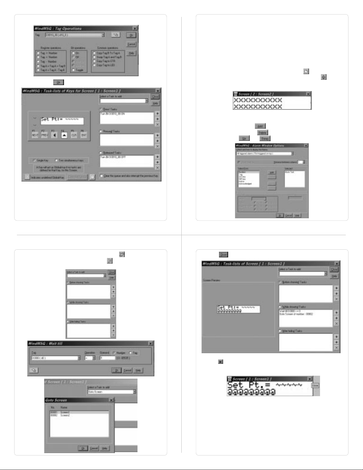
Select Turn bit off task as ‘relesed task’ for the same key.
Select coil. Click to accept the task.
We want to display an alarm when bit 0 of tag D5 turns on. An alarm
object has to be placed on the screen so as to display alarm
condition. But as the space on the screen is limited we will create a
new screen, screen 2, with alarm object on it. This screen will be
triggered when the bit turns on. So in the While showing task list for
the screen no 1, a define ‘wait till’ task followed by ‘goto screen’ task.
So the screen 1 will be displayed till the alarm bit is off. Immediately
after the bit turns on the screen will change and display screen 2.
To create a new screen click on New screen icon . Enter essential
screen information. In screen 2, click on alarm object icon . Click
on the screen. Alarm object will be placed on the screen. Double click
the object to edit.
An alarm dialog box will be displayed. This window will enable user to
select text to be displayed whrn alarm is displayed. Select item from
‘Select From’ list and click . If any item is to be removed select
from ‘selected’ list and click . Sequence of selected items can be
adjusted using the and buttons.
Now go to screen no 1 using ‘select screen’ icon . To define while
showing task list, click on screen task icon . Select ‘While showing
Task’. Add ‘wait till’ and ‘goto screen’ tasks.
Now click to add the tasks to screen task list.
Now click to close screen dialog box.
Page 26

Now click alarm icon to define alarms. Alarm dialog box will
Click to define application Task-list for the application. Here we
be displayed.
Click to add alarms. We want to define only one alarm for tag
D5, so we will select ‘discrete’ Alarms tags. Select Group of alarms,
Tag of group, Alarm Number,
Alarm Text, Alarm Options.
Click to accept
alarms defined.
will define the power-up screen and Global Task-list if any. Select
task from the task-list.
Click to download application.
Select COM port.
Select Application.
Click to download application to HG1X - 252 unit.
Appendix B
Cable Diagrams
Page 27

IDEC Micro3 to HG1X Cable: Pin Configuration
IDEC Part # HG9Z-SCI25A
IDEC Micro Smart to HG1X Cable: Pin Configuration
IDEC Part # HG9Z-SCI25B
Micro3 PLC End
8 Pin Minidin
1
A
2
B
7
GND
8
VCC
HG9Z-SCI25A
HG9Z-SCI25A
HG1X End
DB9 Female
8
RXD
3
TXD
5
GND
5
SHIELD
6
VCC
7
DE
Micro Smart PLC End
8 Pin Minidin
TXD
RXD
GND
SHIELD
VCC
3
4
6,7
8
8
RXD
3
TXD
5
GND
SHIELD
6
VCC
HG1X End
DB9 Female
Programming Cable for HG1X: Pin Configuration
IDEC Part # HG9Z-125A
PC End
DB9 Female
TXD
RXD
GND
2
3
5
2
3
5
HG1X End
DB9 Male
RXD
TXD
GND
Koyo DL 205 to HG1X Cable: Pin Configuration
HG1X End
DB9 Female
TXD
RXD
GND
VCC
3
8
5
6
DL 205 End
6 x 6 Modular
Connector
3
RXD
4
TXD
1
GND
2
VCC
 Loading...