

Page 1

WB2F 2D Code Scanner
User’s Manual
B-1952(0)
Page 2

Introduction
Attention
z
IDEC Corporation holds all rights related to this manual. Unauthorized duplication, reproduction, sales, transfers, or leasing without the express consent of IDEC is prohibited.
z
Information contained in this manual may be changed or updated without notice.
z
Every eort has been made to ensure the accuracy of the information contained in this manual. However, if you do note
any errors or inconsistencies please contact the dealer from which you purchased the product or an IDEC sales representative.
Applicable standards
This product is in compliance with the following standards:
z
IEC/EN 61000-6-1 (2007)
z
IEC 62471 (2006)
z
IEC 61000-6-3 (2006)
z
EN 61000-6-3 (2007)
z
EN 55032 (2012) Class A
z
EN 55024 (2010)
z
UL 60950-1, 2nd Edition, 2011-12-19
z
FCC Part 15 Subpart B Class A (Verication)
z
CSA C22.2 No.60950-1
z
ICES-003 Class A (self-declared)
z
VCCI Class A (compliance conrmed)
FCC Regulations
This device complies with Part 15 of the FCC Rules. Operation is subject to the following two conditions:
(1) This device may not cause harmful interference, and
(2) this device must accept any interference received, including interference that may cause undesired
operation.
NOTE: This equipment has been tested and found to comply with the limits for a Class A digital device, pursuant to
Part 15 of the FCC Rules. These limits are designed to provide reasonable protection against harmful interference
when the equipment is operated in a commercial environment. This equipment generates, uses and can radiate
radio frequency energy and, if not installed and used in accordance with the instruction manual, may cause
harmful interference to radio communications. Operation of this equipment in a residential area is likely to cause
harmful interference in whitch case the user will be required to correct the interference at his own expense.
Canadian Department of Communications Compliance Statement
• CAN ICES-3(A) / NMB-3(A)
For further details on any of the above standards, please contact your sales agent directly.
i
Page 3

2. Installation & wiring 3. Functions 4. Support tool 5. Appendix1. Overview
Introduction
Version Information
The following is the latest version information for the WB2F 2D Code Scanner. Prior to use, conrm the main application
version of the rmware currently installed on the WB2F.
To conrm the rmware version currently installed on the WB2F, refer to "No. 46 Main Application Version Information" of
[5.6 List of Control Commands] located on page 5-20.
Fixes and Improvements
Initial Release A-001.000.00
Main application version
WB2F-100S1B
ii
Page 4

2. Installation & wiring 3. Functions 4. Support tool 5. Appendix1. Overview
Introduction
General terms, abbreviations, and terminology used in this manual
The general terms, abbreviations, and terminology used in this manual are as follows.
Item Denition
WB2F An abbreviation for the WB2F-100S1B.
Communication interface RS-232 Serial Communication Interface
Refers to the Communication Unit WB9Z-CU100 available for purchase separately. The
Communication Unit
Preventing Double Read
Time
Number of characters The sum of 1 byte codes either transmitted or received via the RS-232 interface.
AIM ID An abbreviation for AIM Symbology Identier
AI An abbreviation for Application Identier (standardized by GS1)
Pitch
Skew
Tilt
Reading Timeout A parameter that species the maximum time the WB2F will spend on reading a symbol.
Decode Timeout A parameter that species the maximum time the WB2F will spend on a decode processing.
Receive Buer A storage area that temporarily stores received data.
Send buer A storage area that temporarily stores transmission data.
Quiet Zone Blank region that surrounds the symbol
Control characters
Prex
Sux Character data that is added to the end of output data and communication commands.
Output
Input
DPM
IDEC website www.idec.com
WB9Z-CU100 is a protocol converter that allows the WB2F to connect to RS-232/RS-422/
Ethernet enabled devices.
A parameter that species a time interval between reads to prevent the WB2F from reading
the same code twice.
Rotation of the symbol around the y-axis. Refer to F [5. 2. 3 Angle Characteristics] on
page 5-5.
Rotation of the symbol around the x-axis. Refer toF [5. 2. 3 Angle Characteristics] on page
5-5.
Rotation of the symbol around the z-axis. Refer toF [5. 2. 3 Angle Characteristics] on page
5-5.
ASCII codes 00H - 1FH and 7FH. In this manual, they are expressed using
to F [5. 9 ASCII Code Table] on page 5-22.
Character data that is added to the beginning of output data and communication commands.
Depending on the context, refers to the following: External Output, Communication Output, Status LED
Depending on the context, refers to the following: READ/ENTER button, SELECT button, External Input, Communication Input
An abbreviation for Direct Part Marking. A process used to directly mark parts made out of
materials such as metal and resin with product information such as 2D codes.
. For details, refer
iii
Page 5
2. Installation & wiring 3. Functions 4. Support tool 5. Appendix1. Overview
WarningWarning
CautionCaution
Graphic Symbol Glossary
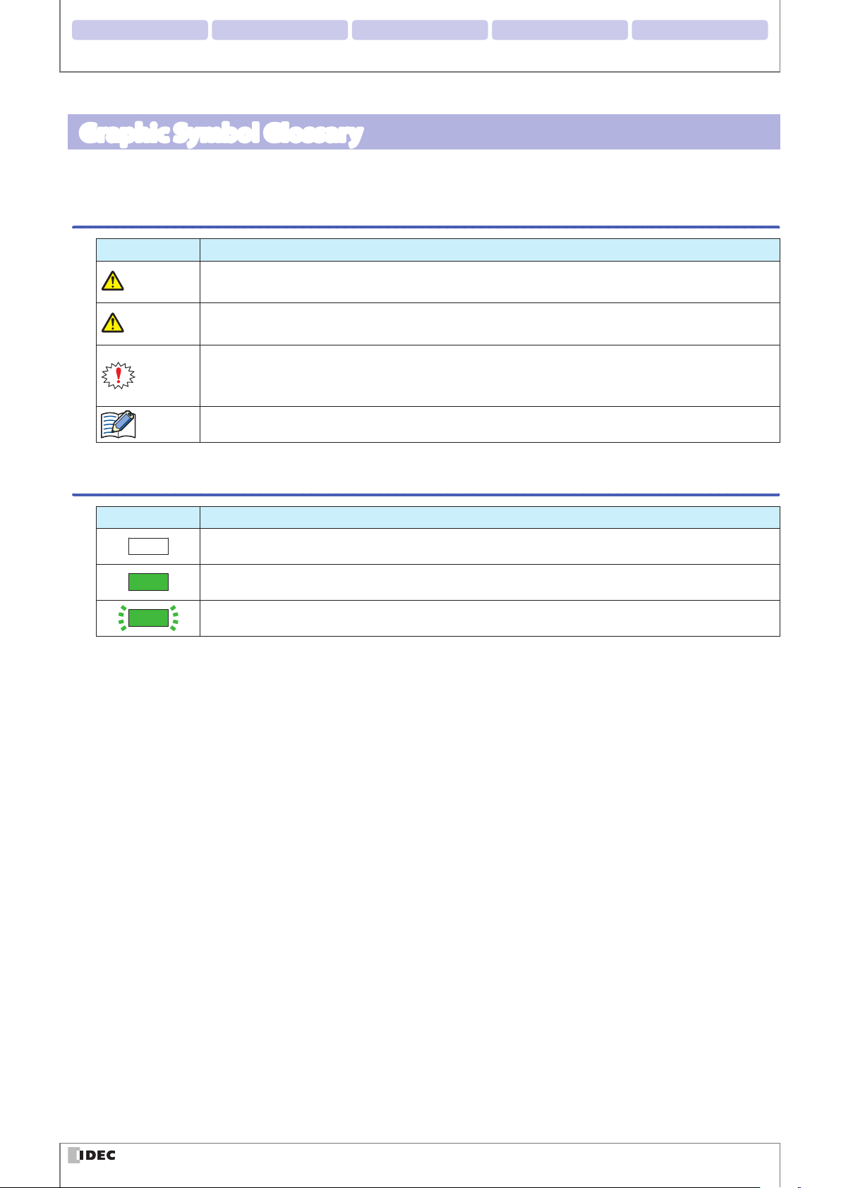
This manual uses the following graphic symbols to simplify explanations:
Notes
Graphic Symbol Description
Failure to operate the product in accordance with the information provided may result in severe personal injury or death.
Failure to operate the product in accordance with the information provided may result in personal
injury or damage to equipment.
Notes information that should be carefully noted. Failure to operate the product in accordance with
the information provided may aect the appearance and performance of the main unit as well as any
peripheral devices.
Denotes additional information that may prove useful for using a given function.
Introduction
Status LED/Position Display LED
Graphic Symbol Description
(*)
(*)
(*)
* In case of Status LED, color will change based on status (green/orange/red). In case of Position LED, a number denoting
position (1/2/3/4) will be shown. In addition, the color of the graphic symbol will be drawn in accordance with the color
of the LED.
Indicates that the LED is turned OFF
Indicates that the LED is turned ON
Indicates that the LED is Flashing
iv
Page 6
2. Installation & wiring 3. Functions 4. Support tool 5. Appendix1. Overview
WarningWarning
CautionCaution
WarningWarning
Introduction
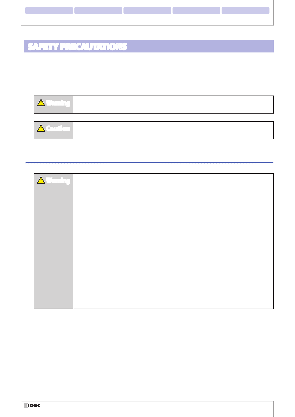
SAFETY PRECAUTATIONS
z
Before installing and wiring this product, operating it, or performing maintenance and inspection, read this manual
carefully and use the product correctly.
z
The degree of possible danger that may occur if the product is mishandled is classied and denoted by "Warning"
and "Caution" symbols. The meaning of each is as follows.
Failure to operate the product in accordance with the information provided may result in severe
personal injury or death.
Failure to operate the product in accordance with the information provided may result in personal injury or damage to equipment.
Safety precautions
z
This product was not designed for use in applications that require a high safety and reliability
standard such as in medical equipment, equipment related to nuclear power, transportation
equipment and devices related to rail, aviation and automotive products. Please do not use
this product for these and/or similar applications.
z
When using this product in applications that may impact human life, such as in the management of chemicals, only do so after taking the utmost care to include all redundancies, failsafes and safety features into the design so as to ensure that human life is not impacted even
if data is mistaken.
z
Do not modify, disassemble, or attempt to repair this product. Doing so may result in electrical shock, damage, re, malfunctions and other other serious accidents.
z
When using this product in situations where it is not built into other equipment, do not use
an integrated power supply. Otherwise there is a risk of re or electric shock.
z
Do not look directly at the scan window or direct the scanner towards other people's eyes
while the LED light is on. There is a risk of causing damage to the eyes.
z
This product has been designed for use in general electronic equipment only. It is not authorized for use in applications that require a high safety/reliability standard where malfunction
or failure of the product may result in severe personal injury or death.
z
Always turn the power supply o before performing any wiring, or mintenance work. Failure
to do so may result in electric shock or malfunction.
v
Page 7
2. Installation & wiring 3. Functions 4. Support tool 5. Appendix1. Overview
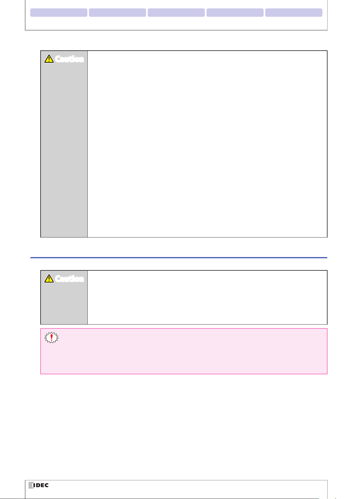
CautionCaution
CautionCaution
Introduction
z
Do not connect the product to a power supply outside the rated power supply voltage range
or to an AC power supply. Otherwise there is a risk of explosion or burnout.
z
Mistakenly wiring the product may cause the internal circuit to be damaged. Wire the input
and output circuits by referring to the connection examples in F P. 2-5 "2. 3. 1 Wiring the RS232 type". This product is not equipped with a protection circuit for a reversed power supply
connection, so there is a risk of damage when the power supply connection is reversed. Use
extreme caution when connecting the power supply.
z
Avoid parallel wiring of the product's wires in the same conduit or duct with high voltage
lines or power lines (inverter power lines in particular) as this may cause malfunction or damage due to the eect of induction noise.
z
If the wires are long and when there is a risk of being aected by power sources or solenoids,
independently wire the product as a general rule.
z
Avoid installing or using the product in the following locations as there is a risk of malfunction or damage.
- Near induction equipment or heat sources
- Locations with many vibrations or shocks
- Dusty and dirty locations
- In an atmosphere with hazardous gases such as suldizing gas
- Locations in direct contact with water, oils, or chemicals
- Outdoors
z
This product is not an explosion-proof product. Conrm that explosion-proof capabilities are
not required when installing the product.
Precautions for Use
z
Use the product in the environment listed in the catalog and manual. If this product is used
in locations with high temperatures, high humidity, condensation, corrosive gas, or excessive
vibration/shock, there is a risk of electric shock, re, and malfunction.
z
The usage environment pollution degree for this product is "pollution degree 2". Use the
product in a pollution degree 2 environment.
(Based on the IEC 60664-1 standard)
z
The power reset time is under 5s. Perform operations 5s after turning the power on.
z
When the load and the unit are connected to dierent power supplies, always turn on the unit's power
supply rst.
z
Install the product so that the scan window is not directly exposed to sunlight or uorescent light.
z
The non-volatile memory equipped on the WB2F can be overwritten 100,000 times.
vi
Page 8
2. Installation & wiring 3. Functions 4. Support tool 5. Appendix1. Overview
Introduction
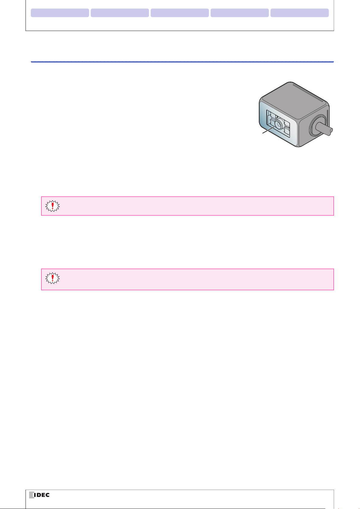
Cleaning
zCleaning the Scan Window
Keep the scan window free of dust, dirt, moisture and scratches as it will negatively
aect scanning performance.
Inspect the scan window periodically and remove any dirt or dust that may have
accumulated.
Scan Window
Cleaning methods
z
To clean the scan window, blow the dust/dirt away with an airbrush, and then gently wipe it o with a cotton swab or a
similarly soft object.
z
If moisture has collected on the scan window, wipe with a soft cloth.
z
Always turn the WB2F power o before cleaning the product.
Do not use organic solvents such as alcohol, thinner or benzene as they may aect the optics of the WB2F.
zCleaning the unit
z
Wipe any dust or dirt o of the WB2F with a soft, dry cloth.
z
If the product is excessively dirty, wipe the surface with a soft cloth that has been soaked in a dilute neutral detergent
solution and thoroughly wrung out. Dry with a soft dry cloth.
Do not use organic solvents such as alcohol, thinner, or benzine as this may alter the housing or strip the
paint.
vii
Page 9
2. Installation & wiring 3. Functions 4. Support tool 5. Appendix1. Overview
Related manuals
Manuals related to the WB2F are as follows. Refer to them together with this manual.
All related manuals are available for download from our website.
Type Manual name Details
B-1952
B-1945
B-1946
B-1963
WB2F 2D Code Scanner
User’s Manual (this manual)
Instruction Sheet:
WB2F 2D Code Scanner
Instruction Sheet:
WB9Z-CU100 Communication Unit
WB9Z-CU100 Communication Unit
User’s Manual
Gives an overview of the functions and capabilities of the
WB2F, and instructions on its use.
Included with the product.
Included with the product.
Gives an overview of the functions and capabilities of the
communication unit as well as instructions on its use.
Introduction
viii
Page 10

Contents
Introduction i
Attention .............................................................................................................................................................. i
Applicable standards ....................................................................................................................................... i
Version Information ........................................................................................................................................ii
General terms, abbreviations, and terminology used in this manual ..........................................iii
Graphic Symbol Glossary .............................................................................................................................iv
Notes ..................................................................................................................................................................................... iv
Status LED/Position Display LED ................................................................................................................................. iv
SAFETY PRECAUTATIONS ..............................................................................................................................v
Safety precautions .............................................................................................................................................................v
Precautions for Use .......................................................................................................................................................... vi
Cleaning .............................................................................................................................................................................. vii
Related manuals ........................................................................................................................................... viii
Contents ix
Overview 1-1
1
1. 1 Checking the packaged product and the product conguration ...............................1-1
1. 2 Part names and functions ..........................................................................................................1-2
1. 3 System conguration ..................................................................................................................1-3
1. 4 Accessories and Peripheral Devices .......................................................................................1-5
Installation & wiring 2-1
2
2. 1 Installation precautions ..............................................................................................................2-1
2. 2 Mounting methods ......................................................................................................................2-3
2. 2. 1 WB2F mounting methods ..................................................................................................................... 2-3
2. 2. 2 Setup symbol position ............................................................................................................................ 2-4
2. 3 Wiring ................................................................................................................................................2-5
2. 3. 1 Wiring Instructions: Connecting the WB2F to the Communication Unit ............................. 2-5
2. 3. 2 Wiring Instructions: Setting up the WB2F without the Communication Unit .................. 2-12
2. 3. 3 Connecting the USB Cable ..................................................................................................................2-15
ix
Page 11

2. Installation & wiring 3. Functions 4. Support tool 5. Appendix1. Overview
Operational Check 3-1
3
3. 1 Performing an Operational Check using a PC ....................................................................3-1
3. 1. 1 Necessary operating environment of the PC ................................................................................ 3-1
3. 1. 2 Installing the Device Driver ................................................................................................................... 3-1
3. 1. 3 Connecting to a PC .................................................................................................................................. 3-2
3. 2 Conrming a Successful Read ..................................................................................................3-3
3. 3 Symbol Read Data Conrmation .............................................................................................3-4
Function 4-1
4
4. 1 Overview ..........................................................................................................................................4-1
Contents
4. 1. 1 Operation mode ........................................................................................................................................ 4-1
4. 1. 2 Operation mode switching operation and status.........................................................................4-3
4. 2 Slave Mode ......................................................................................................................................4-4
4. 2. 1 Switching operation to slave mode ................................................................................................... 4-4
4. 2. 2 Symbol reading ......................................................................................................................................... 4-5
4. 2. 3 Output data additional information ................................................................................................4-15
4. 2. 4 Output data editing ...............................................................................................................................4-20
4. 2. 5 Verication ................................................................................................................................................ 4-22
4. 2. 6 Command alias ........................................................................................................................................4-26
4. 2. 7 Communication command .................................................................................................................4-28
4. 2. 8 Parameter Changeover .........................................................................................................................4-31
4. 2. 9 Image Capture .........................................................................................................................................4-34
4. 2. 10 Image Filter ...............................................................................................................................................4-37
4. 2. 11 I/O ................................................................................................................................................................. 4-40
4. 3 Setup support mode ................................................................................................................. 4-41
4. 3. 1 Switching operation to setup support mode ...............................................................................4-41
4. 3. 2 Reading Success Rate Measurement ...............................................................................................4-44
4. 3. 3 Decoding Processing Time Measurement .....................................................................................4-45
4. 3. 4 Symbol Position Measurement ..........................................................................................................4-46
4. 3. 5 Autotuning ................................................................................................................................................4-48
4. 4 Maintenance mode ................................................................................................................... 4-50
4. 4. 1 Switching operation to maintenance mode ................................................................................. 4-50
4. 4. 2 Maintenance support ............................................................................................................................4-52
4. 4. 3 Firmware updating .................................................................................................................................4-52
4. 5 Master Mode ................................................................................................................................ 4-53
4. 5. 1 Switching to Master Mode ..................................................................................................................4-53
4. 5. 2 Connecting to a PLC ..............................................................................................................................4-53
x
Page 12

2. Installation & wiring 3. Functions 4. Support tool 5. Appendix1. Overview
4. 6 Conguration Item Table ......................................................................................................... 4-54
4. 7 Communication Unit ................................................................................................................ 4-93
4. 7. 1 Overview .................................................................................................................................................... 4-93
4. 7. 2 Names and functions of its parts ......................................................................................................4-94
Appendix 5-1
5
5. 1 Product specications .................................................................................................................5-1
5. 2 Field of view/characteristics ......................................................................................................5-3
5. 2. 1 Reading Range........................................................................................................................................... 5-3
5. 2. 2 Field of View ................................................................................................................................................ 5-4
5. 2. 3 Angle Characteristics ............................................................................................................................... 5-5
Contents
5. 3 Dimensional outline drawings .................................................................................................5-7
5. 4 Troubleshooting ............................................................................................................................5-9
5. 5 Timing Chart ................................................................................................................................ 5-10
5. 5. 1 Scan Operation Timing Chart ............................................................................................................. 5-10
5. 5. 2 External Output Timing Chart ............................................................................................................ 5-11
5. 6 List of Control Commands ...................................................................................................... 5-13
5. 7 Control Commands (Details) ..................................................................................................5-17
5. 8 Check digit calculation method ............................................................................................ 5-21
5. 9 ASCII Code Table ......................................................................................................................... 5-22
5. 10 AIM symbology ID table .......................................................................................................... 5-24
5. 11 GS1-128 Application Identier .............................................................................................. 5-26
5. 12 Initialization Barcode ................................................................................................................ 5-27
5. 13 Sample labels...............................................................................................................................5-28
5. 14 Installing the USB driver .......................................................................................................... 5-31
5. 15 Setting check digit ..................................................................................................................... 5-32
Index A-1
Revision history A-3
xi
Page 13
1
This chapter describes the product conguration of the WB2F, the names and functions of its parts, and the basic system
conguration during operation.
Overview
1. 1
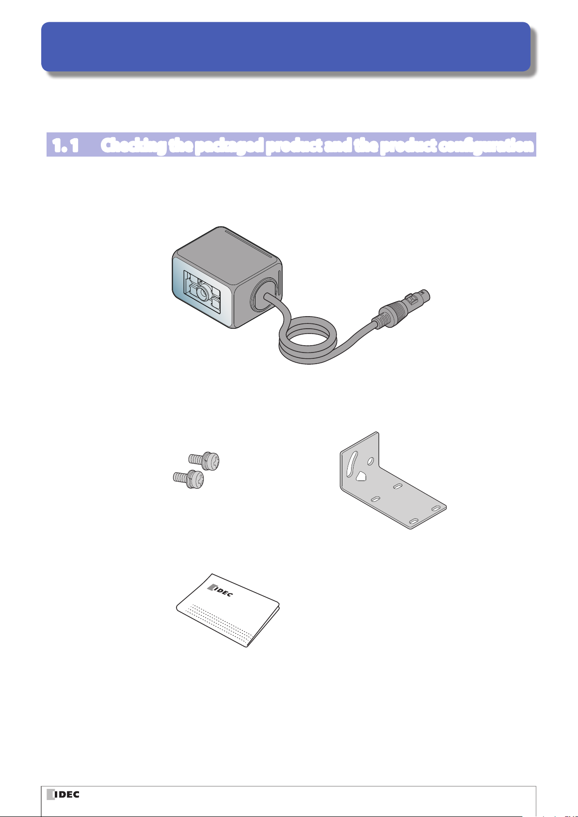
The WB2F is packaged with the following items:
Before using the WB2F, check that the unit and accessories are present and that they have suered no damage.
Checking the packaged product and the product conguration
Unit: 1
Mounting screws (M3): 2
the WB2F is shipped with the
mounting screws attached
Mounting Bracket: 1
Instruction Manual: 1
INSTRUCTION SHEET
WB2F 2D Code Scanner
1-1
Page 14
2. Installation & wiring 3. Operational Check 4. Support tool 5. AppendixOverview
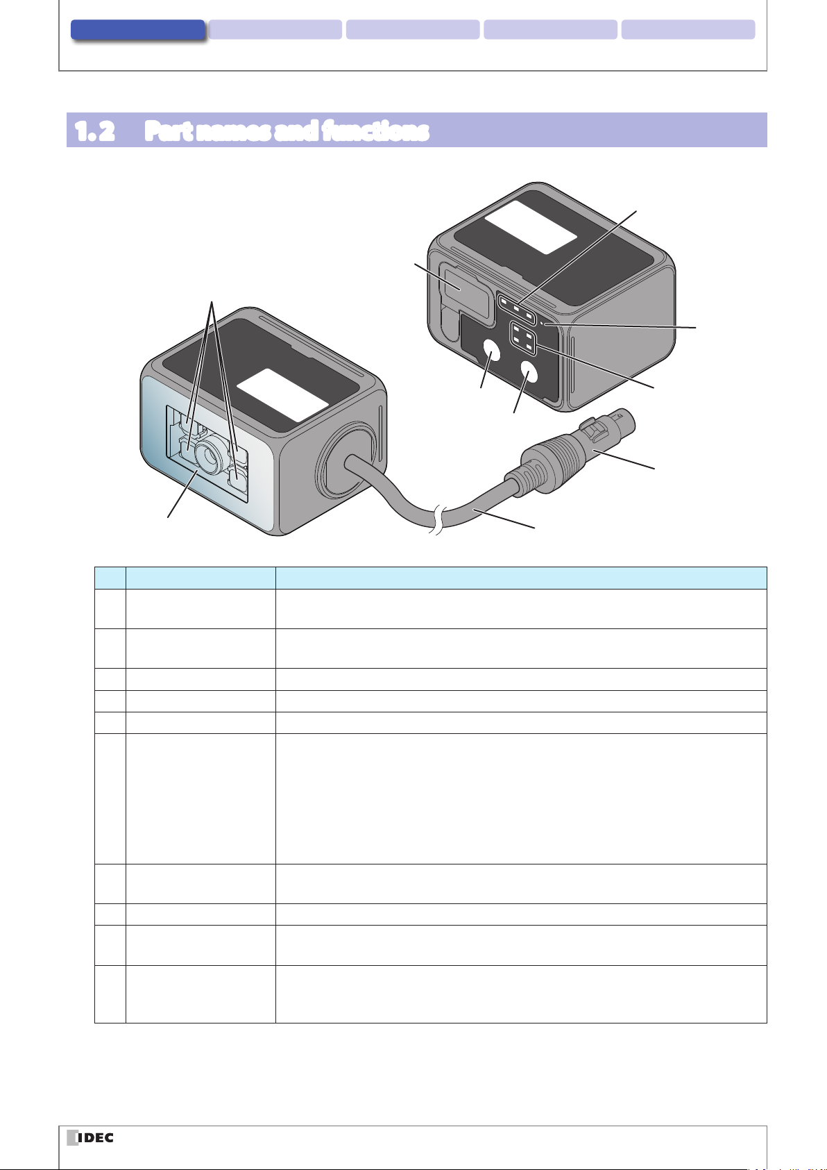
1. 2 Part names and functions
This section describes the names and functions of WB2F parts.
(10)Maintenance Port (USB)
(2)Emitter LED
Scanner
Operational
Surface
(3)SELECT button
(4)READ/ENTER button
Part names and functions
(6)Status LED
(5)Power-ON
Indicator LED
(7)Position LED
Scanner
Reading
Surface
(1)Scan Window
No. Description Function
(1) Scan Window
(2) Emitter LED
(3) SELECT button Used to select various functions
(4) READ/ENTER button Used to conrm various functions that have been selected
(5) Power-ON Indicator LED Green LED will light up when the WB2F's power is on
(6) Status LED
(7) Position LED
(8) Connecting cable Cable length: 2 m
(9) Connector
(10) Maintenance Port (USB)
The window protects the optical components of the WB2F from dust, debris and moisture.
Lights up during scan operation (based on settings, this is not the only time it will light
up) Lighting modes, the number of LEDs that light up etc. can be altered via settings.
The Status LED indicates the operating status of the unit.
(Green): Turns on when reading has succeeded and the read image is matched on com-
parison.
(Orange) : Turns on during a reading operation.
(Red): Turns on when reading fails and the read image is not matched on comparison.
This operation may dier due to the settings.
The status of the Status LEDs also changes due to the unit's operating status.
Displays the Position of the symbol. (1) - (4): The position of the symbol placed in the
WB2Fs FOV will light up on the LED display.
DIN Connector (manufactured by Hosiden, TCP9386, Male) used to provide power to the
WB2F, or connect to the communication unit.
Port that utilizes the USB interface to perform various maintenance operations (USB 2.0,
Mini-B). If connecting to a host device, use its accessory or any commercially available
USB cable.
(8)Connecting cable
(9)Connector
1-2
Page 15
2. Installation & wiring 3. Operational Check 4. Support tool 5. AppendixOverview
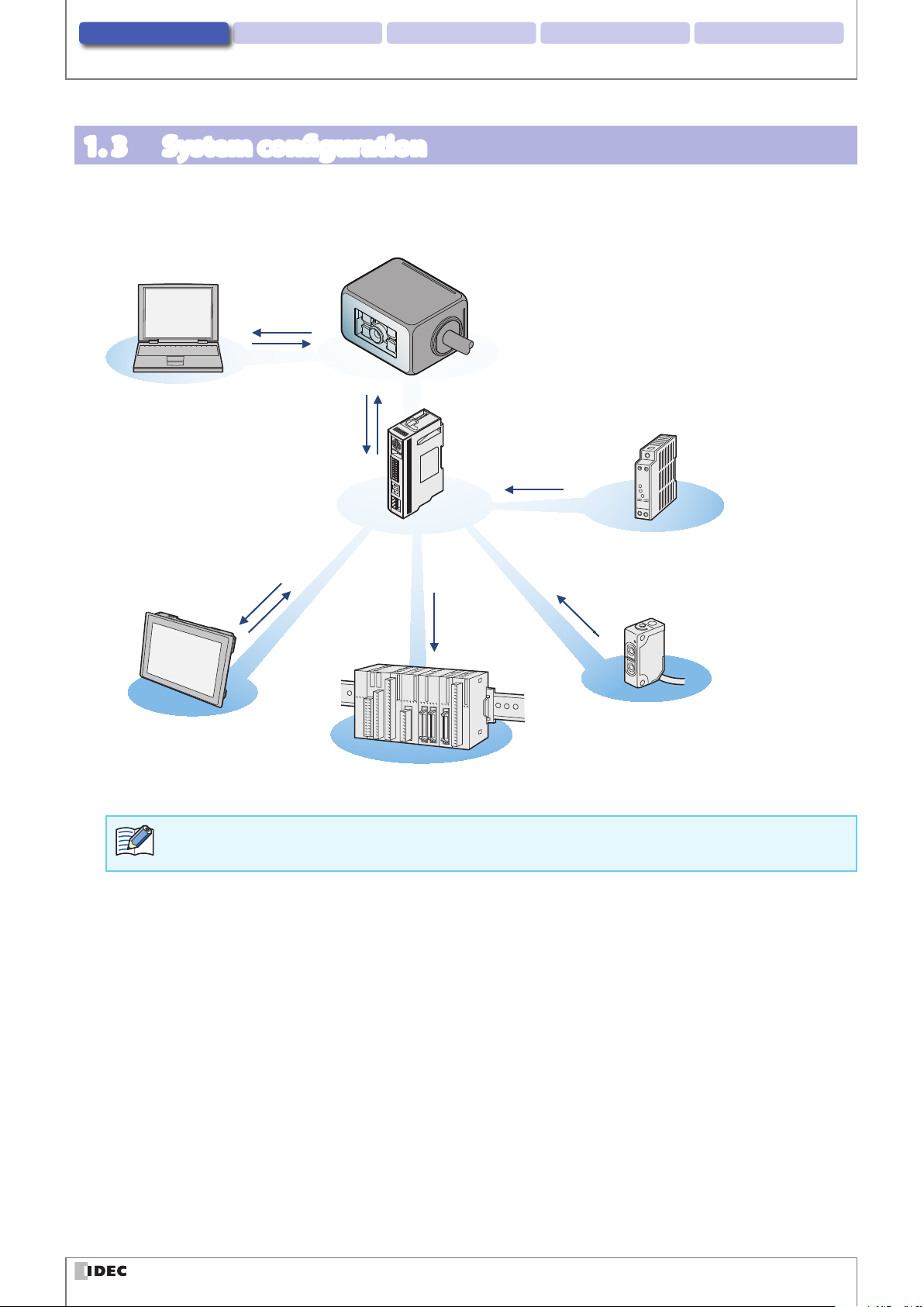
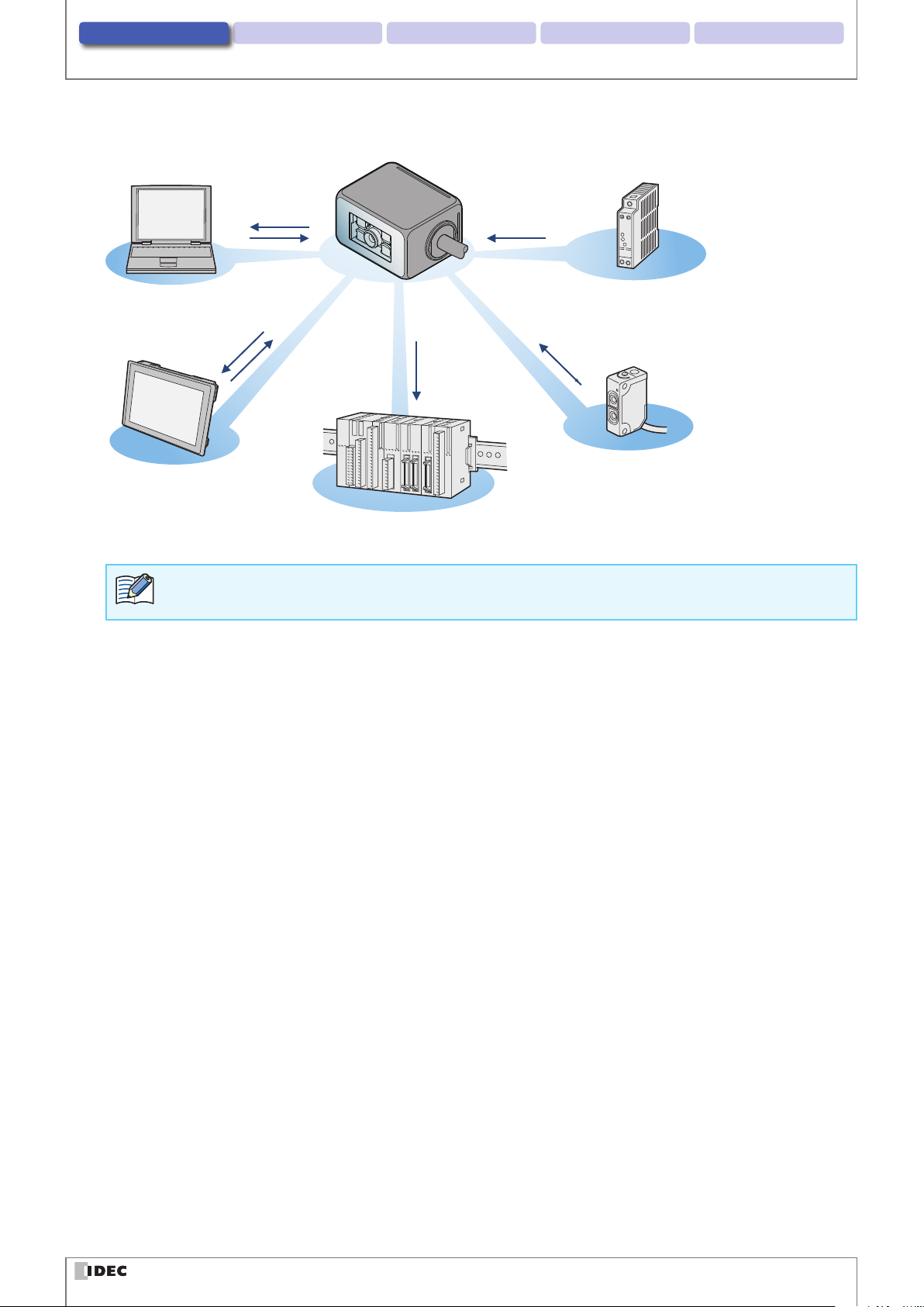
1. 3 System conguration
The typical system conguration when operating the WB2F is as follows.
With the Communication Unit
USB
(for Maintenance
Purposes)
WB2F
PC
5V DC power supply
RS-232
I/Os
(DIN Connector)
System conguration
24V DC
Power Supply
Communication Unit
RS-232
RS-422
Ethernet
External Output
Host device
PLC, External Light Source
24V DC Power Supply
External Input
Sensor
The device driver must be installed prior to connecting the WB2F to a PC via USB. Refer to F [5. 14 Installing
the USB driver] on page 5-31 for installation instructions.
1-3
Page 16
2. Installation & wiring 3. Operational Check 4. Support tool 5. AppendixOverview
Without the Communication Unit
USB
(for Maintenance
Purposes)
System conguration
5V DC Power Supply
PC
WB2F
RS-232
External Output
Host device
PLC, External Light Source
5V DC Power Supply
External Input
Sensor
The device driver must be installed prior to connecting the WB2F to a PC via USB. Refer to F [5. 14 Installing
the USB driver] on page 5-31 for installation instructions.
1-4
Page 17
2. Installation & wiring 3. Operational Check 4. Support tool 5. AppendixOverview
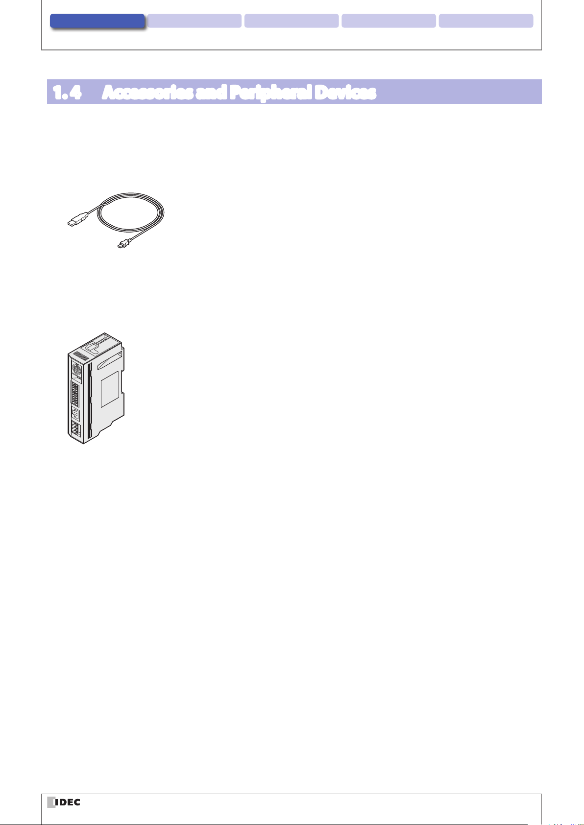
1. 4 Accessories and Peripheral Devices
The WB2F's accessories and peripheral devices are as follows:
zAccessories
USB Maintenance Cable
HG9Z-XCM42
zPeripheral Devices
WB2F compatible communication unit
WB9Z-CU100
Accessories and Peripheral Devices
1-5
Page 18
2
This chapter describes WB2F installation locations, mounting methods, and wiring the WB2F to peripheral devices.
Installation & wiring
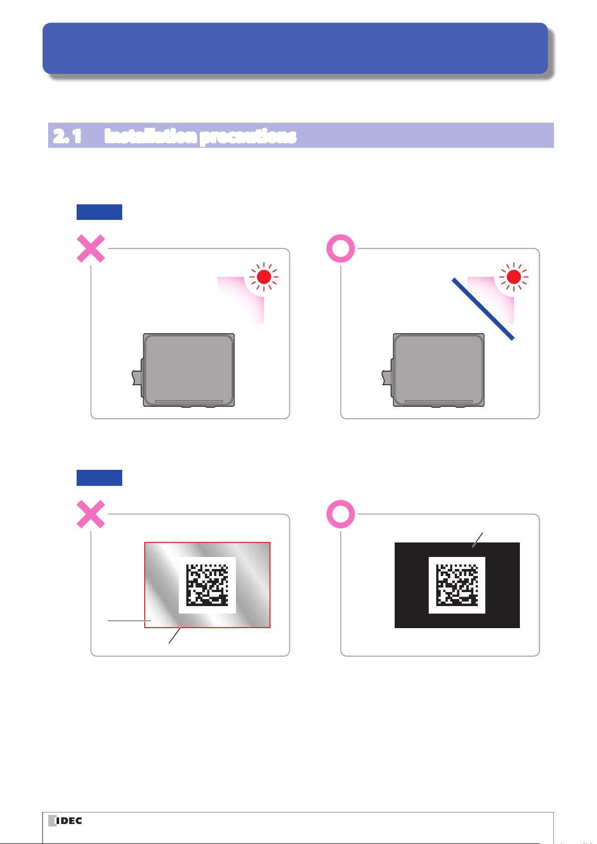
2. 1 Installation precautions
z
Install the unit so that ambient light such as sunlight, uorescent light, and photoelectric switches does not enter the
scan window.
Otherwise the unit may not be able to read symbols or it may erroneously read them.
Example Take measures to block ambient light or to change the position of photoelectric switches.
Block
the light
z
Do not install a reective body (metal or mirror) along the light receiving axis.
Otherwise the unit may not be able to read symbols or it may erroneously read them.
Example Tape over any mirrored/reective surfaces with black tape to prevent the reection of light.
Black tape
Mirror
Field of view
2-1
Page 19
Installation & wiring 3. Operational Check 4. Function 5. Appendix1. Overview
Installation precautions
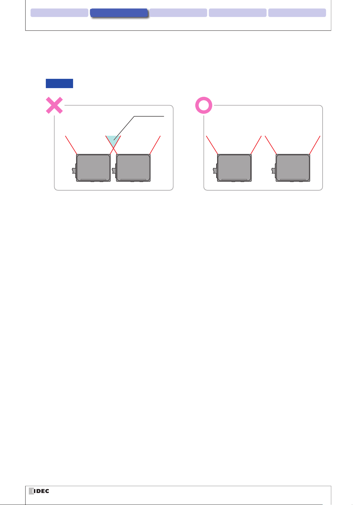
z
When installing WB2F units in a series, install them so the emitted LED light does not overlap (so they do not interfere
with each other).
Otherwise the unit may not be able to read symbols or it may erroneously read them.
Example Install the WB2F units by increasing the spacing between them.
Interference
2-2
Page 20
Installation & wiring 3. Operational Check 4. Function 5. Appendix1. Overview
2. 2 Mounting methods
2. 2. 1 WB2F mounting methods
Double check the dimensions of the mounting hole and drill a hole in the mounting board
1
For the dimensions of the mounting hole, refer to F [5. 3 Dimensional outline drawings] on page 5-7.
Mounting methods
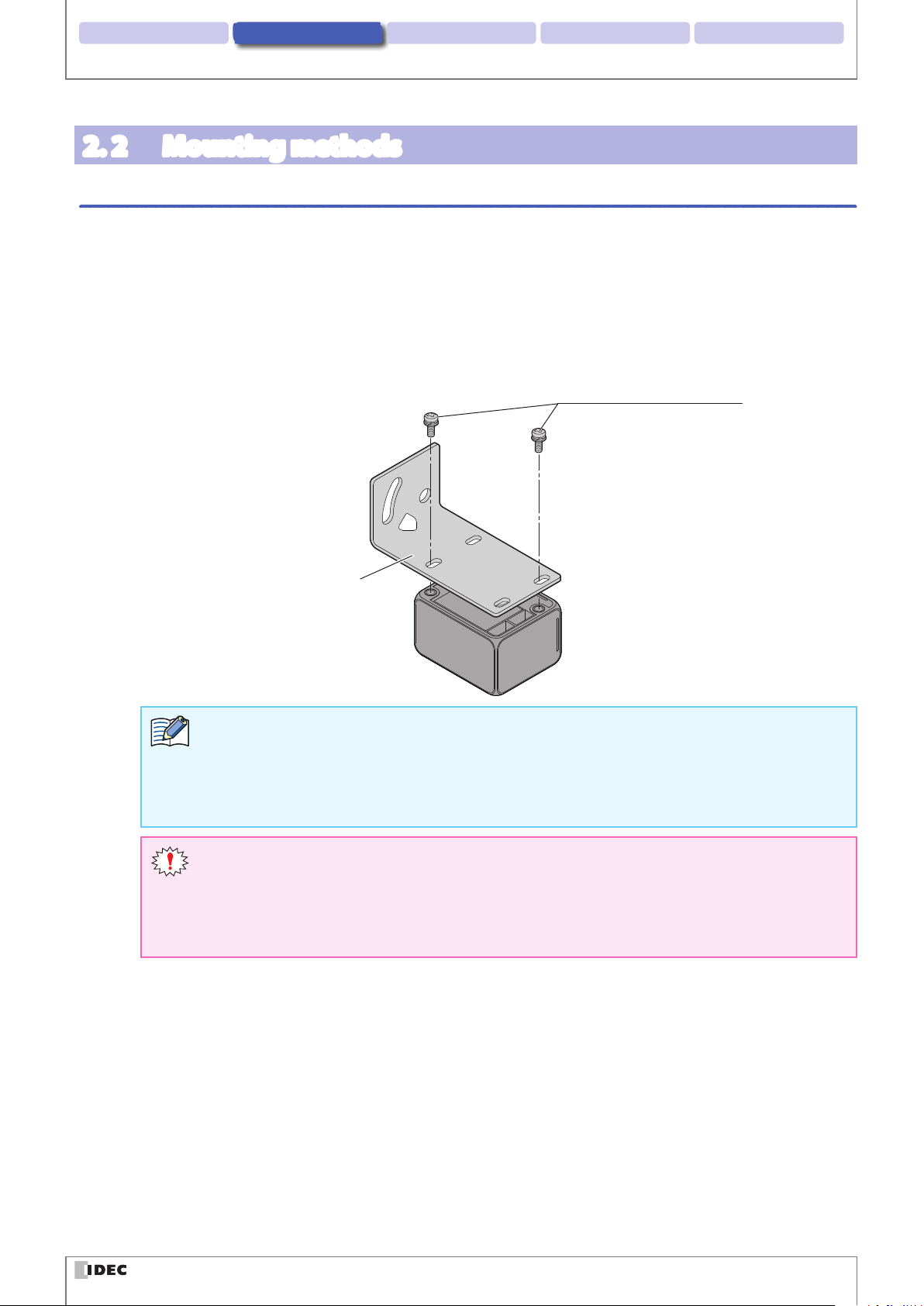
If you use the brackets provided, use the two mounting screws (also provided) to secure the bracket to
2
WB2F before you secure the bracket to the mounting board.
If you do not use the brackets provided, use the two mounting screws to secure the WB2F to the mounting
board.
The tightening torque for the product mounting screws is 0.4 to 0.5 N·m.
Mounting Screws (Included)
M3 SEMS x 6 (2 screws)
Mounting Bracket
(Included)
z
Instead, use two M3 screws with an eective thread length of 3 to 5 mm and secure the WB2F to the
plate.
z
If you use a bracket other than the one that was included, make sure that the dimensions of the
mounting holes is at most Φ3.4mm
z
When using the WB2F, remove the protective lm on the scan window.
the
z
If you attach to a plate that is thicker than 2.3 mm, do not use the included mounting screws.
z
If, during installation, the WB2F is exposed to excessive force (e.g. the mounting screws are
tightned excessively, the product is hit with a hammar, the base of the cable is exposed to excessive stress (pulled strongly, bent etc.)), it could undermine the IP65 protective structure of the
WB2F.
2-3
Page 21
Installation & wiring 3. Operational Check 4. Function 5. Appendix1. Overview
Mirror reflection area (dead zone)
Setup symbol position range
Mounting methods
2. 2. 2 Setup symbol position
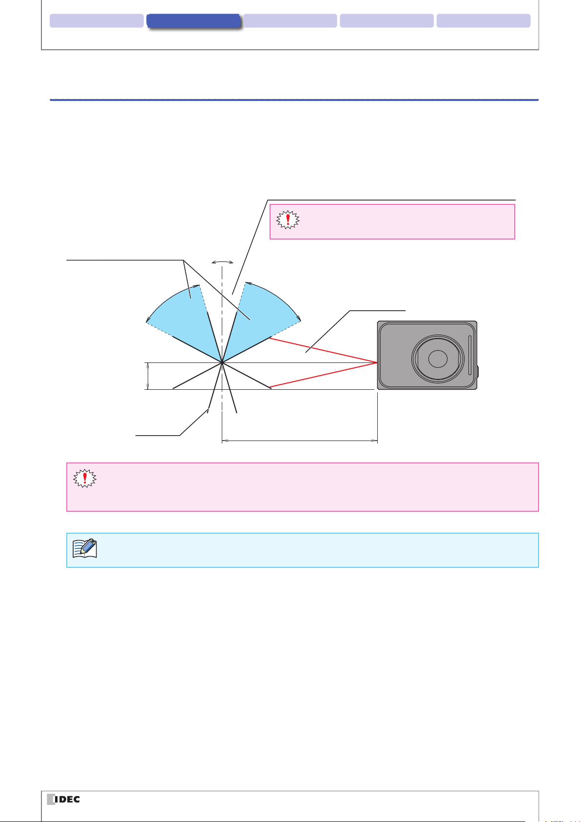
Install the unit so that symbol skew θ is in the range of +15° ≤ θ ≤ +60° and -60° ≤ θ ≤ -15°.
For the reading range, refer to F [5. 2. 1 Reading Range] on page 5-3. For other angular characteristics, refer to F
[5. 2. 3 Angle Characteristics] on page 5-5. For detailed dimensions, refer to F [5. 3 Dimensional outline drawings] on
page 5-7.
e.g. Changing Emitter LED pattern to 4
Do not read symbols in the skew range -15° < θ <
+15°.
θ
+
+15 to +60°
-
-
15 to -60°
Field of view
z
z
To adjust the WB2F's position while conrming the symbol's read success rate, follow the steps described in
F
9.4mm
Symbol
Skew in a range of -15° < θ < +15° is in the mirror reection area (dead zone), so reading performance
100mm
may drastically decrease in ways such as the unit not being able to read or misreading symbols
The mirror reection area (dead zone) will dier based on the emitter LED's lighting pattern.
[4. 3 Setup support mode] on page 4-41.
2-4
Page 22
Installation & wiring 3. Operational Check 4. Function 5. Appendix1. Overview
Wiring
2. 3 Wiring
2. 3. 1 Wiring Instructions: Connecting the WB2F to the Communication Unit
For an overview of the communication unit refer to F [4. 7 Communication Unit] on page 4-93. For dimensions of the
communication unit refer to F [5. 3 Dimensional outline drawings] on page 5-7.
zConnecting to the WB2F
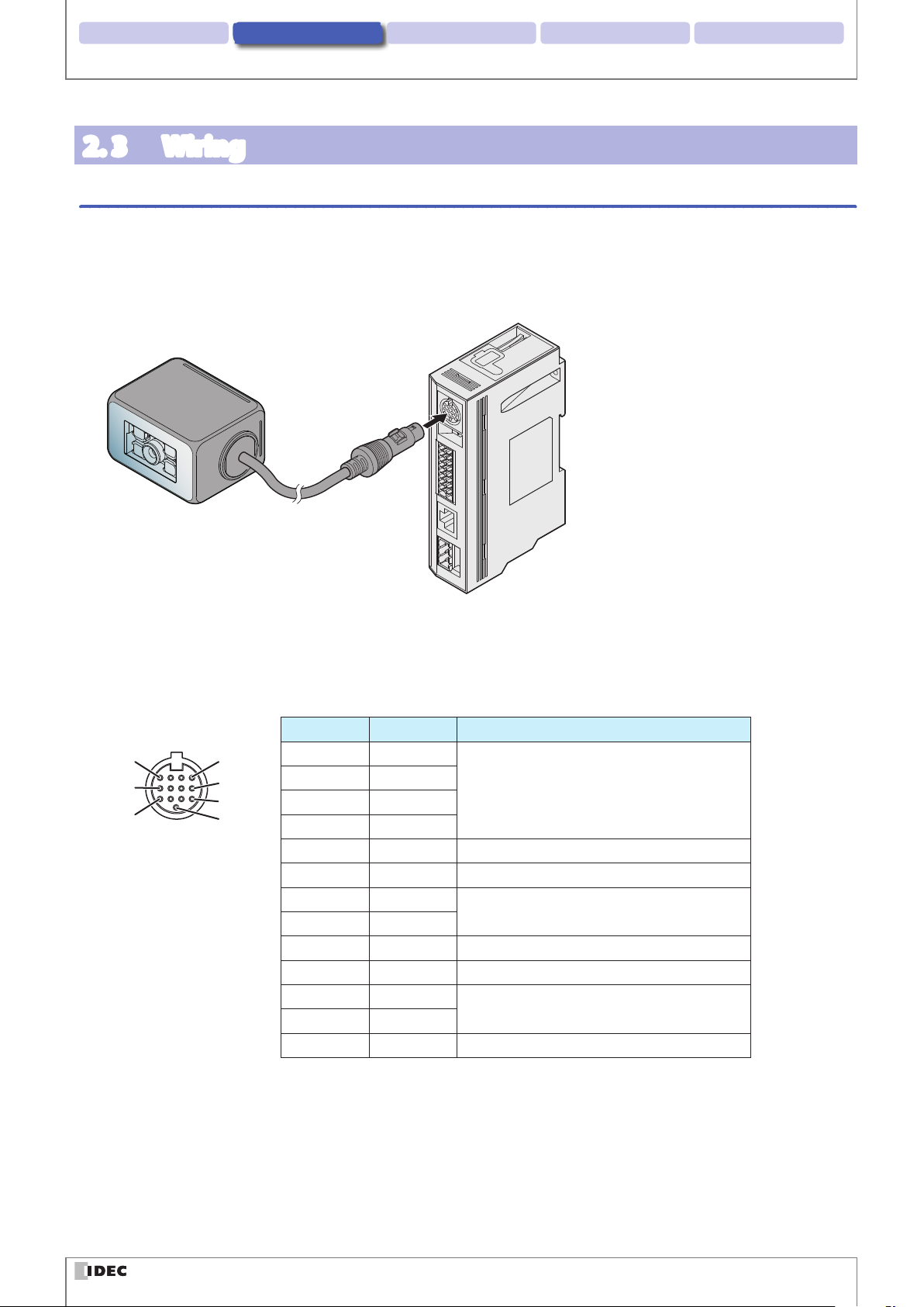
The WB2F and the Communication Unit's connection diagram is the following:
Communication Unit
WB2F
DIN Connector
zConnector Pin Assignment
Communication Unit's connector pin assignment is as follows:
Scanner Port
DIN Connector Pin Number Description Function
1 Out_0
2 Out_1
3 Out_2
4 Out_3
5 5VDC WB2F Power Supply (+V)
6 S_RD WB2F Received Data (RS-232)
7 In_0
8 In_1
9 0V WB2F Power Supply (-V, SG Shared)
10 S_SD WB2F Transmission Data (RS-232)
11 S_RS
12 S_CS
13 0V WB2F Power Supply (-V, SG Shared)
Output from the WB2F
(NPN Open Collector)
Input to the WB2F
RS-232 Control Signal
12
4
8
1
5
9
13
2-5
Page 23
Installation & wiring 3. Operational Check 4. Function 5. Appendix1. Overview
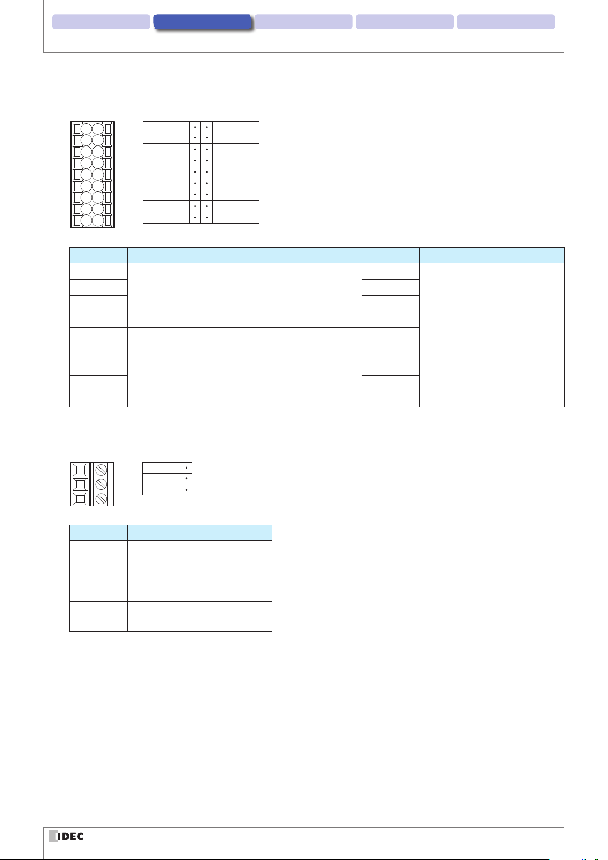
Input/Output/RS-232/RS-422 port
Connector for Input/Output/RS-232/RS-422 port
SDA
SDB
RDA
RDB
SG
RD
SD
CS
RS
Description Function Description Function
SDA
SDB OUT_0
RDA OUT_1
RS-422 Connection with a Host Device
RDB OUT_2
SG RS232/RS422 Connection with Host Device OUT_3
RD
CS IN_1
RS-232 Connection with a Host Device
RS NC Unused
OUT_COM
OUT_0
OUT_1
OUT_2
OUT_3
IN_COM
IN_0
IN_1
NC
OUT_COM
Output from the WB2F
IN_COM
Input to the WB2FSD IN_0
Wiring
External Power Port
Connector for an External Power Port
DC24V
0V
FE
Description Function
DC24V Power Supply (+V) for Communi-
cation Unit
0V Power Supply (-V) for Communi-
cation Unit
FE Functional Ground for Communi-
cation Unit
2-6
Page 24
Installation & wiring 3. Operational Check 4. Function 5. Appendix1. Overview
CautionCaution
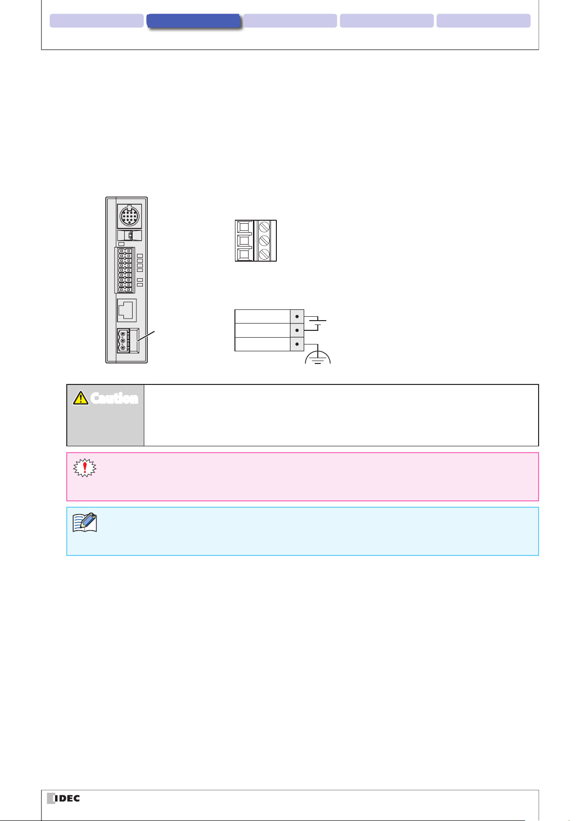
zConnecting the Power Supply
There are two methods for connecting the power supply
z
Using an external power supply
z
Using PoE (Power over Ethernet)
Using an Exernal Power Supply
Connect the 24V DC power supply adaptor to the communication unit's external power supply port.
Connector for the External Power Port
Pin assignment for the External Power Supply Port
Wiring
24V DC
External
Power Port
z
Do not reverse the power supply connections under any circumstances. Doing so may result
0V
FE
24V DC
in damage.
z
Use the product within the rated power supply voltage range. Otherwise there is a risk of explosion or burnout.
z
Always turn o the WB2F's power supply before wiring the product.
z
Do not simultaneously use an external power supply and PoE.
z
Use an AWG12 to 24 Cable for wiring.
z
If using as a UL certied product, the external power source must be at most 24V DC, 8A, 100VA Limited
Power Source or Class 2 Power Source.
z
A normal type fuse rated 2.5A, 60V DC is built into the product.
2-7
Page 25
Installation & wiring 3. Operational Check 4. Function 5. Appendix1. Overview
Wiring
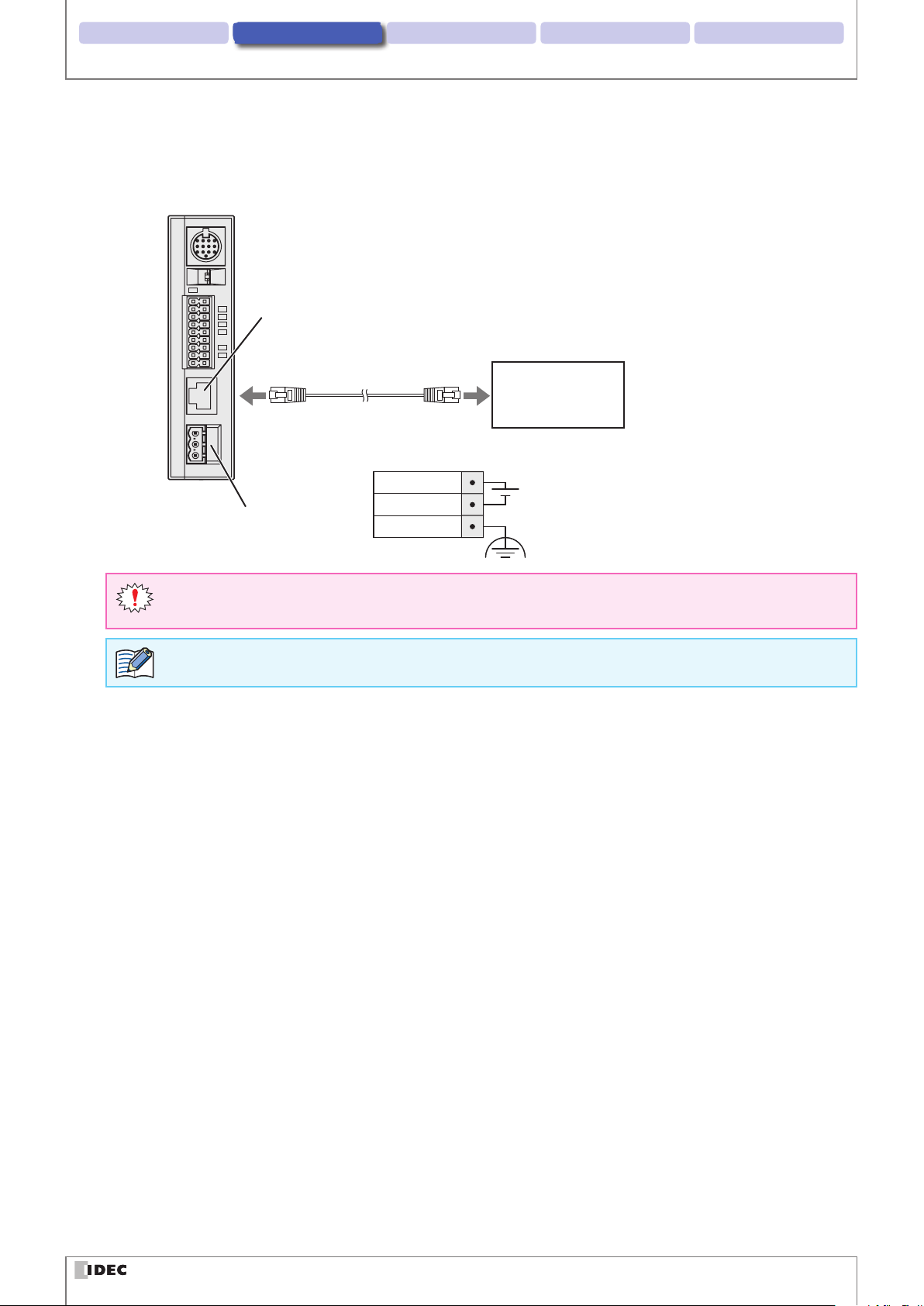
Using PoE
Connect the PoE to the Communication Unit's Ethernet Port. Even if using PoE, ground the FE terminal of the external
power supply's port connector.
Ethernet Port
Ethernet
PoE
(Alternative A/B)
Pin assignment for the External Power Supply Port Connector
24V DC
External
Power Port
z
Turn the communication unit's power to OFF prior to performing any wiring work.
z
Do not simultaneously use an external power supply and PoE.
0V
FE
24V DC
PoE is treated as Class 0.
2-8
Page 26
Installation & wiring 3. Operational Check 4. Function 5. Appendix1. Overview
Wiring
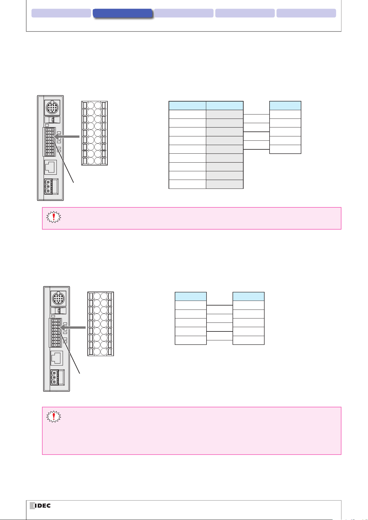
zRS-232 wiring
If connecting the WB2F to a host device such as programmable display or a computer using RS-232, do so according to
the following wire instructions:
Connector for Input/Output/
RS-232/RS-422 port
Host device
Pin NumberDescription
2RXD
3TXD
7RTS
8CTS
5GND
Connector for Input/Output/
RS-232/RS-422 port
Description
SD
RD
CS
RS
SG
1DCD
4DTR
6DSR
Input/Output/RS-232/RS-422 port
9RI
D-sub 9-pin connector
z
Ethernet/RS-232/RS-422 cannot simultaneously use more than two types of communication.
z
Use an AWG16 to 24 Cable for wiring.
zRS-422 wiring
If connecting the WB2F to a host device such as programmable display or a computer using RS-422, do so according to
the following wire instructions:
Connector for Input/Output/
RS-232/RS-422 port
Host device
Description
RDA(RD+)
RDB(RD-)
SDA(SD+)
SDB(SD-)
SG
Connector for Input/Output/
RS-232/RS-422 port
Description
SDA(SD+)
SDB(SD-)
RDA(RD+)
RDB(RD-)
SG
Input/Output/RS-232/RS-422 port
z
Ethernet/RS-232/RS-422 cannot simultaneously use more than two types of communication.
z
Do not use a cable that is longer than 500m.
z
If using a cable that is longer than 30m, use a shielded cable and connect the shield to the FE terminal.
Wire the shield with sucient consideration of the environment.
z
Use an AWG16 to 24 Cable for wiring.
2-9
Page 27
Installation & wiring 3. Operational Check 4. Function 5. Appendix1. Overview
Wiring
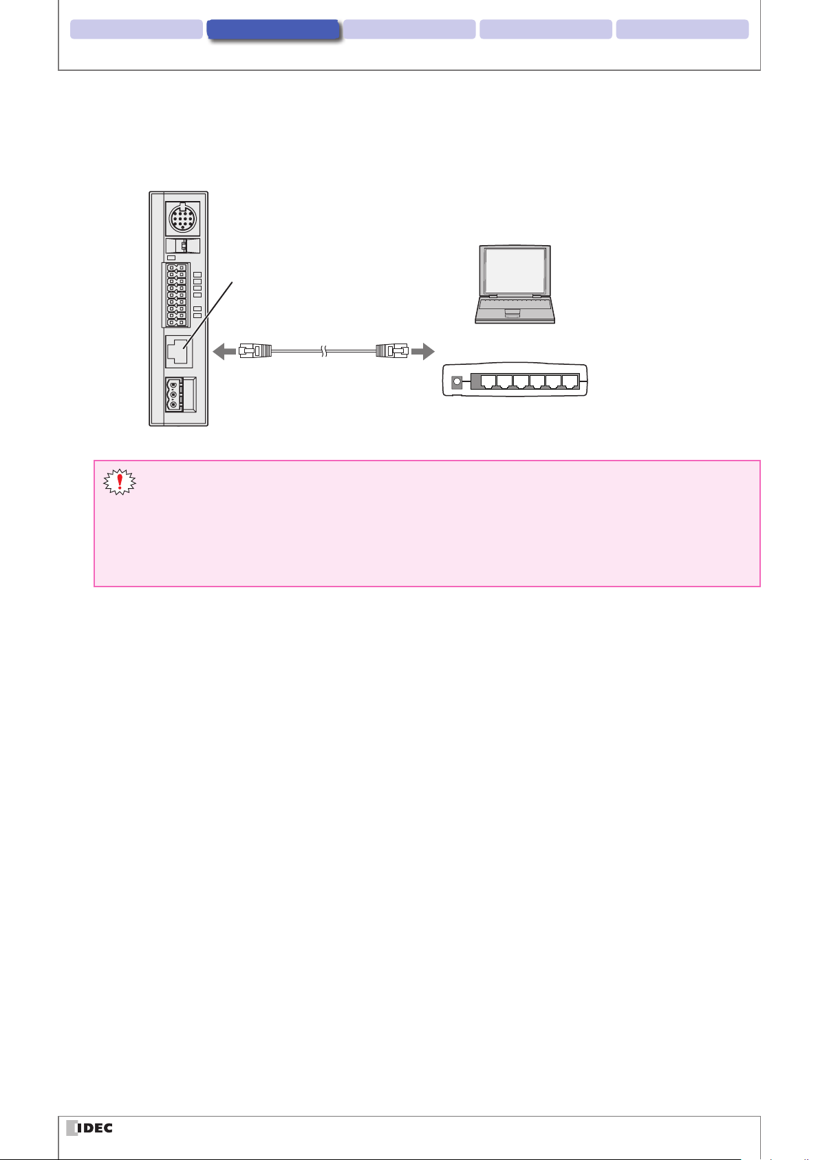
zWiring for Ethernet Communication
If connecting the WB2F to a host device such as programmable display or a computer using an ethernet connection, do
so according to the following wire instructions:
Ethernet Port
Ethernet
Host device
Ethernet Hub
z
Ethernet/RS-232/RS-422 cannot use more than two types of communication at once.
z
Connect the PoE to the Communication Unit's Ethernet Port. Even if using PoE, ground the FE terminal of
the external power supply's port connector.
z
Use a cable rated over category 5.
z
Do not use a cable that is longer than 100m.
z
If using a cable that is longer than 30m use a shielded cable.
2-10
Page 28
Installation & wiring 3. Operational Check 4. Function 5. Appendix1. Overview
CautionCaution
CautionCaution
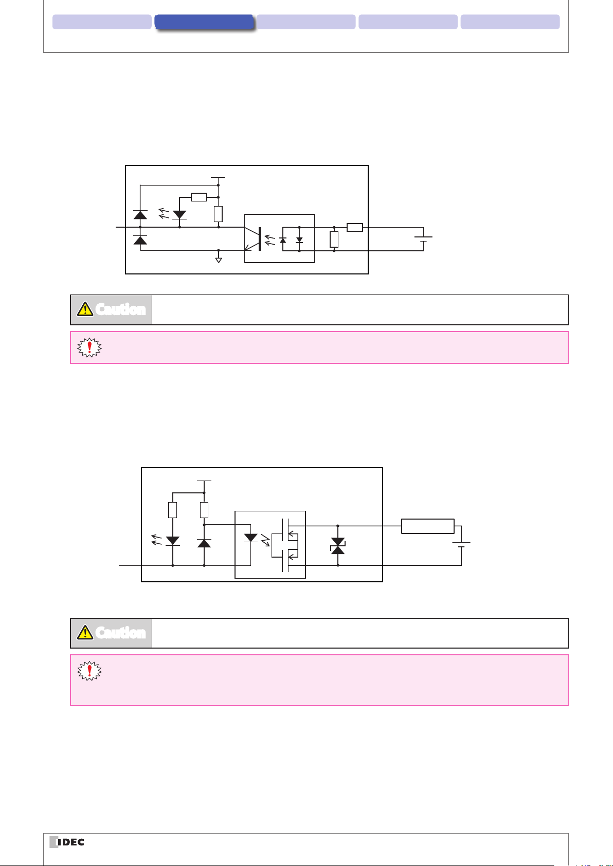
zWiring for External Input
External Input is a trigger input used to turn Read Request ON/OFF.
External Input will operate given the following voltage input (VIL:0-5V, VIH: 15-28.8V).
Refer to the following example prior to wiring the WB2F.
Communication Unit
VCC
R
Input to
the WB2F
R
R
0V
Miswiring may cause damage to internal circuitry.
IN_0,1
R
IN_COM
Wiring
24V DC
(28.8V DC max.)
Use an AWG16 to 24 Cable for wiring.
zWiring for External Output
External Output is used to determine read success/read failure during read operations.
Refer to the following example prior to wiring the WB2F.
Communication Unit
VCC
R R
Output
from WB2F
(NPN Open Collector)
Miswiring may cause damage to internal circuitry.
OUT_0-3
OUT_COM
Load
24V DC
(30V DC max.)
z
If the Load and the WB2F are connected to separate power supplies, make sure that you turn the WB2F's
power on rst.
z
Use an AWG16 to 24 Cable for wiring.
2-11
Page 29
Installation & wiring 3. Operational Check 4. Function 5. Appendix1. Overview
Wiring
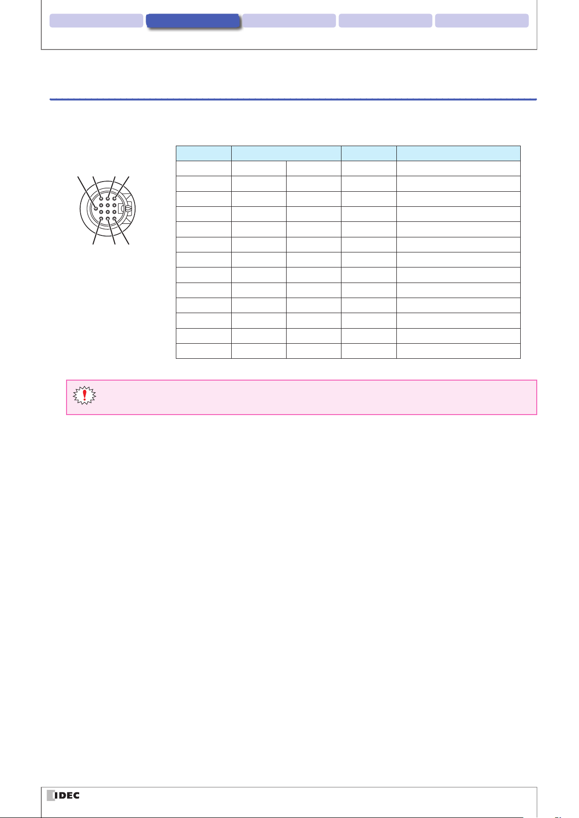
2. 3. 2 Wiring Instructions: Setting up the WB2F without the Communication Unit
zConnector Pin Assignment
The WB2F's connector pin assignment is as follows.
DIN Connector Pin Number Wire color Discription Function
13
9
15
4812
1 Gray Red Dot OUT0 External Output 0
2 Gray Black Dot OUT1 External Output 1
3 White Red Dot OUT2 External Output 2
4 White Black Dot OUT3 External Output 3
5 Orange Red Dot2 +5V Power Supply +
6 Pink Black Dot TXD RS-232 Transmission Data
7 Orange Red Dot IN0 External Input 0
8 Orange Black Dot IN1 External Input 1
9 Orange Black Dot2 0V Power Supply (- SG Shared)
10 Pink Red Dot RXD RS-232 Received Data
11 Yellow Red Dot CTS RS-232 Control Signal
12 Yellow Black Dot RTS RS-232 Control Signal
13 – – NC No connection
Either the DIN Connector Shell or the Cable Shield is not connected to the main body
Make the determination to connect to FE or SG depending on the level of surrounding noise
2-12
Page 30
Installation & wiring 3. Operational Check 4. Function 5. Appendix1. Overview
5V DC±0.25V
WB2F
CautionCaution
Wiring
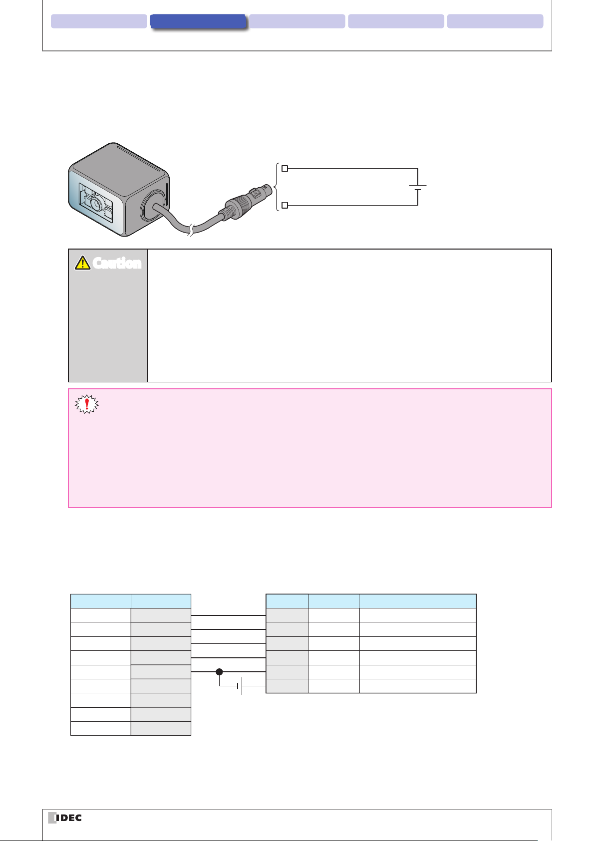
zWiring the power supply
Connect pin number 5 (+ 5V) to the 5V DC power supply + side and pin number 9 (0 V) to the - side. Read the following
notes carefully and refer to the wiring example below before attempting to wire the power supply.
Pin Number5: Power Supply +
DIN Connector
Pin Number9: Power Supply -
z
Do not reverse the power supply connections under any circumstances. Doing so may result
in damage.
z
Use the product within the rated power supply voltage range. Otherwise there is a risk of explosion or burnout.
z
When using this product in situations where it is not built into other equipment, do not use
an integrated power supply. Otherwise there is a risk of re or electric shock.
z
Avoid parallel wiring of the product's wires in the same conduit or duct with high voltage
lines or power lines (inverter power lines in particular) as this may cause malfunction or damage due to the eect of induction noise.
z
The power reset time is under 5s. Perform operations 5s after turning the power on.
z
Always turn o the WB2F's power supply before wiring the product.
z
If the wires are long and when there is a risk of being affected by power sources or solenoids, independently wire the product as a general rule.
z
If you elongate the cable via a DIN connector, be careful of short circuit between adjacent terminals
and consider the subsequent voltage drop of the power supply and use a cable thicker diameter than
AWG28. If the entire cable exceeds a length of 2.8m, there is a possibility that the it will adversely eect
noise immunity. Do so only after thoroughly conrming that the WB2F's performance is not impacted.
zRS-232 wiring
When connecting the unit to a host device such as an operator interface or a computer via RS-232, wire it referring to the
following example.
WB2FHost device
Pin NumberDescription
D-sub 9-pin connector
2RXD
3TXD
7RTS
8CTS
5GND
1DCD
4DTR
5V DC
6DSR
9RI
Pin Number6Description
TXD
10 RXD
11 CTS
12 RTS
9 0V
5 +5V
Function
RS-232 Transmission Data
RS-232 Receive Data
RS-232 Control Signal
RS-232 Control Signal
Power Supply (- SG Shared)
Power Supply +
2-13
Page 31

Installation & wiring 3. Operational Check 4. Function 5. Appendix1. Overview
Main circuit
CautionCaution
(26.4V DC max.)
WB2F
Main circuit
CautionCaution
zWiring for External Input
External Input is a trigger input used to turn Read Request ON/OFF.
The external trigger input operates as a non-voltage input or a voltage input (VIL: 1.0 V, VIH: 4.0 V-VCC).
Refer to the following example prior to wiring the WB2F.
WB2F
VCC
Wiring
R
R
Mistakenly wiring the product may cause the internal circuit to be damaged.
Pin Number 7: IN0
Pin Number 8: IN1
zWiring for External Output
External Output is used to determine read success/read failure during read operations.
Refer to the following example prior to wiring the WB2F.
Pin Number1-4: OUT0-3
0V
Load
Non-voltage contact
24V DC
Mistakenly wiring the product may cause the internal circuit to be damaged.
When the load and the unit are connected to dierent power supplies, always turn on the unit's power
supply rst.
2-14
Page 32

Installation & wiring 3. Operational Check 4. Function 5. Appendix1. Overview
2. 3. 3 Connecting the USB Cable
zUSB connector pin assignment
USB connector is Mini-B (Female) type.
Pin Number Signal name Function
1 VBUS bus power
2 D- Data-
3 D+ Data+
4 NC No connection
5 GND Ground
The WB2F cannot be powered via the USB connector.
USB Connector (Mini-B)
5
1
Wiring
zConnecting the USB connector
When connecting the unit to a host device, rmly insert the USB connector straight into the USB port on the host device
in the correct orientation.
Host device USB port
USB-A Connector
To connect the WB2F, open the Maintenance Port Hatch and insert the USB Mini-B connector.
Maintenance Port
(USB Port)
USB Mini-B Connector
2-15
Page 33

3
This section will describe how to check the WB2F's operations.
Operational Check
3. 1 Performing an Operational Check using a PC
3. 1. 1 Necessary operating environment of the PC
Check to ensure that the PC fullls the following conditions.
Item Details
OS Windows 7 / 8 / 8.1 /10
Communication Port USB2.0 or later
3. 1. 2 Installing the Device Driver
Prior to connecting the WB2F to a PC you must rst install the USB device driver.
In order to install, refer to F [5. 14 Installing the USB driver] on page 5-31.
3-1
Page 34

2. Installation & wiring Operational Check 4. Function 5. Appendix1. Overview
CautionCaution
Performing an Operational Check using a PC
3. 1. 3 Connecting to a PC
zIf you use a communication unit
If you use the WB2F with the communication unit, refer to F [2. 3. 1 Wiring Instructions: Connecting the WB2F to the
Communication Unit] on page 2-5 for wiring instructions.
After completing wiring, turn power ON
WB2F Communication Unit
Pigtail Cable
DIN Connector
USB Mini-B Connector
DC Power Supply
24V DC
USB-A Connector
USB Cable
PC
zIf you do not use a communication unit
If you use the WB2F without the Communication Unit refer to F [2. 3. 2 Wiring Instructions: Setting up the WB2F with-
out the Communication Unit] on page 2-12.
After completing wiring, turn power ON
WB2F
DC Power Supply
Pigtail Cable
5V DC
USB Mini-B Connector
USB-A Connector
USB Cable
PC
z
Note, the DC power supply voltage requirements varies depending on whether you use a
communication unit or not. Using a voltage level other than what is specified within this
manual may result in damage and/or malfunction.
z
Do not reverse the Power Supply connection. Doing so may result in damage.
3-2
Page 35

2. Installation & wiring Operational Check 4. Function 5. Appendix1. Overview
3. 2 Conrming a Successful Read
You can use the WB2F to conrm that a symbol was successfully read.
Operate based on the procedure below.
Place the symbol within the Reading Range
1
2D Code
Barcode
Push the READ/ENTER button while the power is ON
2
Emitter LED continuously lights up as reading begins
Conrming a Successful Read
Power-ON Indicator LED
Due to the WB2F's settings, there are symbols that cannot be read. If you read a symbol double check the
settings to ensure that the symbol is enabled.
You can conrm the Status of a read simply by looking at the Status LED lights
3
During Reading Operation Read Success Time Read Failure
Status LED
(O) (G)(R)
During
Reading Operation
The Status LED (Orange) will continuously be ON during Reading Operations but
will turn OFF once Reading Operations
are terminated
The Status LED settings can be changed. The settings here describe the default settings.
After a successful read the green status
LED will turn ON (300ms)
Status LED
(O) (G)(R)
Read Success
Status LED
(O) (G)(R)
Read Failure
After a read failure, or a reading timeout,
the red status LED will turn ON (300ms)
3-3
Page 36

2. Installation & wiring Operational Check 4. Function 5. Appendix1. Overview
3. 3 Symbol Read Data Conrmation
Conrm the data read by the WB2F by using a PC.
Operate based on the procedure below.
Install a generic terminal software onto the PC
1
WB2F's reading management will be done via the generic terminal software
Start up the generic terminal sfotware, select the port the WB2F is connected to and begin communications
2
The Connector Port can be viewed from [Device Manager]
Because you are connecting via USB, there is no need to separately set communication speed.
Place the symbol within the reading range
3
Transmit the following command from a PC to the WB2F
4
Emitter LED continuously lights up as reading begins
Symbol Read Data Conrmation
Request
Read Start ^ get CR
The prex and sux of Control Commands varies based on settings. The explanation in this manual assumes that factory default settings have been maintained.
Read Data can be conrmed via PC from the data the WB2F transmits
5
Read results can be determined by checking the Read data.
Read Result
Read Success — Such as 123456789 CR
Read Failure or
Read Time Out
The prex and sux of the read data varies based on settings. The explanation in this manual assumes
that factory default settings have been maintained.
Prex Mnemonic Sux
Global Prex Barcode Data Global Sux
— ? CR
Control command (Transmitted Data PC)
Read Data (Data received from PC)
LF
LF
LF
3-4
Page 37

4
This chapter describes the functions of the WB2F.
Function
4. 1 Overview
4. 1. 1 Operation mode
The functions that the WB2F can execute dier by the operation mode.
There are four operation modes: slave mode, setup support mode, maintenance mode, master mode.
Slave mode
This mode is used during normal operation. Slave mode has the following functions.
Function Details Reference page
Symbol reading This function reads a symbol and outputs the reading results.
Output data additional information
Output data editing
Verication
Command alias
Communication command
Parameter Changeover
Image Capture
Image Filter
I/O Function
This function adds various types of data when outputting the
symbol reading results data.
This function outputs the symbol reading results data after editing it according to the specied method.
This function matches the symbol reading results data with
the master data, judges whether or not it is matched, and outputs that.
This function executes the control commands "start symbol
reading" and "stop symbol reading" with other strings.
This function transmits and receives data with the connected
host device via the WB2F communication interface.
This function automatically switches from Read Algorithm to
Imaging parameters
This function stores code images within the WB2F during the
decoding process
This function digitally correct captured images to improve
reading performance.
This function utilizes external input and output terminals in
order to determine the WB2F's operation and condition status.
F
F
F
F
F
F
F
F
F
F
Page 4-5
Page 4-15
Page 4-20
Page 4-22
Page 4-26
Page 4-28
Page 4-31
Page 4-34
Page 4-37
Page 4-40
4-1
Page 38

2. Installation & wiring Function3 Operational Check 5. Appendix1. Overview
Overview
Setup support mode
This mode is used to check the installation position and reading status of the WB2F. Setup support mode has the following function.
Function Details Reference page
Read Success Rate Measurement
Decode Processing Time Measurement
Symbol Position Measurement
This function outputs and displays Read Success Rate for a given symbol.
This function outputs and displays the minimum, maximum
and average symbol decoding time.
This function outputs and displays a symbol's position information (coordinates)
F
F
F
Page 4-44
Page 4-45
Page 4-46
This function automatically adjusts settings to optimal param-
Auto-tuning
eters for a given symbol and saves the settings in a parameter
F
Page 4-48
table.
Maintenance mode
This mode is used to maintain the WB2F after installation and to perform actions when problems occur. Maintenance
mode has the following functions.
Function Details Reference page
Maintenance support
Firmware updating This function updates the WB2F rmware.
Master mode
This function forcibly operates the unit with the factory default
settings.
F
F
Page 4-52
Page 4-52
This mode is used to connect to a PLC with using its communication protocol.Master mode has the following functions.
Function Details Reference page
PLC connection
This function directly write reading results into the data memory of a PLC (programmable logic controller).
F Page 4-53
4-2
Page 39

2. Installation & wiring Function3 Operational Check 5. Appendix1. Overview
Normal usage
4. 1. 2 Operation mode switching operation and status
The operation mode is switched using the READ/ENTER button or communication commands.
For the communication commands, refer to F [4. 2. 7 Communication command] on page 4-28.
Unit power supply
Off
Unit power
supply On
Overview
Master mode
Slave mode
For details on the operation modes, refer to the following.
z
Slave mode ................................................................ F Page 4-4
z
Setup support mode ............................................. F Page 4-41
z
Maintenance mode ................................................ F Page 4-50
z
Master Mode ............................................................. F Page 4-53
Maintenance
mode
Setup support
mode
Be aware that if you change the operation mode without executing the control command "Save setting
values" after changing the set value, the set value will return to the state before change.
4-3
Page 40

2. Installation & wiring Function3 Operational Check 5. Appendix1. Overview
4. 2 Slave Mode
This operation mode is used during normal operation. Use the unit in this mode after installation.
Slave mode has the following functions.
z
Symbol reading .......................................................F Page 4-5
z
Output data additional information ................F Page 4-15
z
Output data editing ...............................................F Page 4-20
z
Verication ................................................................F Page 4-22
z
Command alias ........................................................F Page 4-26
z
Communication command .................................F Page 4-28
z
Paramter Changeover ...........................................F Page 4-31
z
Image Capture.. .......................................................F Page 4-34
z
Image Filter ...............................................................F Page 4-37
z
I/O .................................................................................F Page 4-40
Slave Mode
4. 2. 1 Switching operation to slave mode
There are two methods to switch to slave mode.
Use the methods according to the situation.
The status LEDs (red/orange/green) will turn o when switching to slave mode.
Method 1 Turn on the power to the unit. (Do not push the READ/ENTER button)
Turn on power supply
Method 2 Input the "switch to slave mode" control command.
Status LED
(O) (G)(R)
OFF
Status LED
Host device
Control command
Switch to slave mode
4-4
(O)(R)
OFF
(G)
Page 41

2. Installation & wiring Function3 Operational Check 5. Appendix1. Overview
4. 2. 2 Symbol reading
The symbol reading reads symbols and outputs the reading result.
Refer to F [4. 6 Conguration Item Table] on page 4-54 for details on code reading functions and their vari-
ous settings.
zSymbol Reading Method
There are three methods to start reading (reading request ON).
Method 1 Push the READ/ENTER button.
Slave Mode
Status LED
(O) (G)(R)
Method 2 Input Control Command [Start Reading].
Control command
Host device
Start Reading
Method 3 Turn External Input ON.
Turn External
Pin Number 7: IN0
Input ON
Non-voltage contact
Status LED
(O) (G)(R)
Status LED
(O) (G)(R)
z
Do not use multiple methods to turn the reading request ON/OFF.
z
Prior to setting External Input to trigger the reading request ON, set External Input function to [Start Reading]. For details refer to F [4. 2. 11 I/O] on page 4-40.
z
Reading Results can be set to reect Status LED, External Output and the Communication Interface.
z
The Status LED (Orange) will turn ON during Reading Operations. To customize Interlock Control, Lighting
Patterns, and Light On Times, refer to F [4. 6 Conguration Item Table] on page 4-54.
4-5
Page 42

2. Installation & wiring Function3 Operational Check 5. Appendix1. Overview
Slave Mode
zSymbol Reading
There are three types of Symbol Reading.
z
Single Read...... ..........................................................F Page 4-6
-Edge Activation. ....................................................F Page 4-7
-Level Activation ....................................................F Page 4-8
z
Multi-read Sequential Output ............................F Page 4-9
z
Multi-read Batch Output ......................................F Page 4-10
Single Read
For a single read: Once the Reading Request is turned on, the symbol reading operation commences. Once either Reading
Success is attained or Reading Time Out elapses, the Reading result is output. 1 read is executed per 1 Reading Request.
There are two types of single read operations.
z
Edge Activiation ......................................................F Page 4-7
z
Level Activation .......................................................F Page 4-8
4-6
Page 43

2. Installation & wiring Function3 Operational Check 5. Appendix1. Overview
Slave Mode
Edge Activation
After detecting that Reading Request has been activated (OFF → ON), symbol reading will commence.
If the Reading Time Out time has been set to anything other than innite, Edge activation will occur. For details refer to
[4. 6 Conguration Item Table] on page 4-54.
F
If Reading Request was turned on by External Input, conditions for activating Stop Reading is one of the following:
z
Reading Success
z
Reading Timeout Elapsed
To control the READ/ENTER button or Reading Request using control commands, refer to F [Start Reading and Stop
Reading conditions for each Reading Request] on page 4-11.
The following timing chart is an example of an operation with the External Input.
Reading Request
Emitter LED
Reading Processing
Data Output
External Output
(OK/NG)
External Output
(Busy)
ON
OFF
ON
OFF
ON
OFF
ON
OFF
[Reading Failure][Reading Success]
Lighting ON Time
Reading Timeout Reading Timeout
Reading
Execute
[1]
OK
Reading
Execute
[1]
NG
Reading
Result
[1]
OK
Reading
Execute
[2]
NG
The filter time is enabled only
if external input is used for read
oeprations
The filter time is enabled only
if external input is used for read
oeprations
Reading
Execute
[3]
NG
Reading
Result
NG
z
Operation of the External Input and the External Output will vary depending on settings parameters.
z
If Reading Linked Control parameter is enabled, the Status LED (orange) will turn ON when symbol reading
starts. Turns o when either the illumination time elapses or symbol reading stops.
z
If Reading Linked Control parameter is enabled, the Status LED (Green/Red) will turn ON when symbol reading
stops. Turns o when either the illumination time elapses or symbol reading starts.
z
If Reading Linked Control parameter is enabled, the WB2F will determine Reading Success/Reading Failure or
Verication Match/Verication Un-match when symbol reading stops and perform output control based on the
parameters that are set.
4-7
Page 44

2. Installation & wiring Function3 Operational Check 5. Appendix1. Overview
Slave Mode
Level Activation
If Reading Request is turned ON, symbol reading commences and as long as Reading Request remains ON, symbol reading will continue.
If Read Time Out time is set to innite, Level activate will occur. For details refer to F [4. 6 Conguration Item Table] on
page 4-54.
If Reading Request was turned ON by External Input, conditions for activating Stop Reading is one of the following:
z
Reading Success
z
External Input OFF (Reading Request OFF)
To control reading requests using the control command, refer to F [Start Reading and Stop Reading conditions for
each Reading Request] on page 4-11.
The following timing chart is an example of an operation with External Input.
Reading Request
LED Lighting
Reading Processing
Data Output
External Output
(OK/NG)
External Output
(Busy)
ON
OFF
ON
OFF
ON
OFF
ON
OFF
Illumination time
Reading
Execute
[1]
OK
Reading
Result
[1]
OK
[Reading Failure][Reading Success]
Reading
Execute
[1]
NG
Reading
Execute
[2]
NG
Stop Reading
Reading
Execute
[3]
NG
Reading
Result
NG
z
Operation of the External Input and the External Output will vary depending on settings parameters.
z
If Reading Linked Control parameter is enabled, the Status LED (orange) will turn ON when symbol reading is
ON. Turns oFF when either the illumination time elapses or symbol reading stops.
z
If Reading Linked Control parameter is enabled, Status LED (Green/Red) will turn ON when symbol reading
stops. Turns oFF when either the illumination time elapses or symbol reading starts.
z
If Reading Linked Control parameter is enabled, the WB2F will determine Reading Success/Reading Failure or
Verication Match/Verication Un-match when symbol reading stops and perform output control based on the
parameters that are set.
4-8
Page 45

2. Installation & wiring Function3 Operational Check 5. Appendix1. Overview
Reading Processing
Slave Mode
Multi-Read Sequential Output
If Reading Request is turned ON, symbol reading commences and will continue for as long as Reading Request remains
ON. The WB2F will output the Reading Result for each symbol that is read.
Once Reading Request is turned OFF, symbol reading will stop.
if Reading Timeout is set to innite, Level Activate will occur. For all other cases, Edge Activate will occur.
For more details refer to F [4. 6 Conguration Item Table] "Symbol Reading" on Page 4-58.
If Reading Request was turned ON by external input and level activation, conditions for activating Stop Reading is as follows:
z
External Input OFF
To control Reading Request using control commands, refer to F [Start Reading and Stop Reading conditions for each
Reading Request] on page 4-11.
The following timing chart is an example of an operation with both the External Input and Level Activation
[Reading Failure][Reading Success]
Reading Request
Emitter LED
ON
OFF
ON
OFF
Lighting ON Time
Preventing Double
Read Time
Preventing Double
Read Time
Stop Reading Stop Reading
Data Output
External Output
(OK/NG)
External Output
(Busy)
z
Preventing Double Read Time setting range is 100ms to 25,500ms
z
Even if the Preventing Double Read Time has passed, symbol reading will not begin until communication
response has been established.
z
To prevent reading the same symbol twice, the WB2F will not acknowledge symbols with the same symbology and data as the prior symbol during the Preventing Double Read Time. However, this does not apply to
symbols that have either dierent symbology or data.
z
If you turn Reading Request OFF before the WB2F is able to read a single symbol, it will be treated as a Reading Failure.
z
Operation of the External Output will change based on how its settings are congured.
z
If Reading Linked Control parameter is enabled, the Status LED (orange) will turn ON when symbol reading is
ON. Turns OFF when either the Illumination Time elapses or symbol reading stops.
z
If Reading Linked Control parameter is enabled, the Status LED (Green/Red) will turn ON when symbol reading stops. It will turn OFF when the Illumination time elapses, or symbol reading starts.
z
If Reading Linked Control parameter is enabled, the WB2F will determine Reading Success/Reading Failure or
Verication Match/Verication Un-match when symbol reading stops and perform output control based on
the parameters that are set.
ON
OFF
ON
OFF
Reading
Execute
[1]
OK
Reading
Execute
[2]
NG
Reading
Result
[1]
OK
Reading
Execute
[3]
OK
Reading
Execute
[N]
NG
Reading
Result
[2]
OK
Reading
Execute
[1]
NG
Reading
Execute
[2]
NG
Reading
Execute
[3]
NG
Reading
Result
NG
4-9
Page 46

2. Installation & wiring Function3 Operational Check 5. Appendix1. Overview
Slave Mode
Multi-Read Batch Output
If Reading Request is turned ON, symbol reading commences and will continue for as long as the Reading Request remains
ON. Once the Reading Request is turned OFF, symbol reading will cease and the Reading Results will be output in batch.
The maximum number of symbol data that can be ouput at once is 32. Symbol data for the Symbol Reading past that will
be discarded.
If the Reading Timeout is set to innite, Level Activate will occur. For all other cases, Edge Activate will occur.
For more details, refer to F [4. 6 Conguration Item Table] on page 4-54.
If the Reading Request was turned ON by the external input and level activation, conditions for activating the Stop Reading is as follows:
z
External Input OFF
To control the Reading Request using control commands, refer to F [Start Reading and Stop Reading conditions for
each Reading Request] on page 4-11.
The following timing chart is an example of an operation with both the External Input and Level Activation
[Reading Failure][Reading Success]
Reading Request
Emitter LED
ON
OFF
ON
OFF
Lighting ON Time
Preventing Double
Read Time
Preventing Double
Read Time
Stop Reading Stop Reading
Reading Processing
Data Output
External Output
(OK/NG)
External Output
(Busy)
Reading
Execute
ON
OFF
ON
OFF
z
The sum of the characters of Reading Results [1] to [N] must be under 10,000 characters.
[1]
OK
Reading
Execute
[2]
OK
Reading
Execute
[N-1]
OK
Reading
Execute
[N]
NG
Reading
Result
[1]
OK
Reading
Result
[N-1]
Reading
Execute
[1]
NG
Reading
Execute
[2]
NG
Reading
Execute
[3]
NG
Reading
Result
NG
If the total number of characters exceeds 10,000, the accuracy of the output results is not guaranteed.
z
Preventing Double Read Time setting range is 100ms to 25,500ms
z
To prevent reading the same symbol twice, the WB2F will not acknowledge symbols with the same symbology and data as the prior symbol during the Preventing Double Read Time. However, this does not apply to
symbols that have either dierent symbology or data.
z
The External Output, the Status LED (Green/Red) will show only the WB2F's last Reading Result.
z
Operations of the External Output and the Status LED will change based on how settings are congured
z
If Reading Linked Control parameter is enabled, the Status LED (orange) will turn ON when symbol reading
starts. Turns oFF when either the Illumination Time elapses or symbol reading stops.
z
If Reading Linked Control parameter is enabled, the Status LED (Green/Red) will turn ON when symbol reading stops. It will turn OFF when the Illumination Time elapses, or symbol reading starts.
z
If Reading Linked Control parameter is enabled, the WB2F will determine Reading Success/Reading Failure or
Verication Match/Verication Un-match when symbol reading stops and perform output control based on
the parameters that are set.
4-10
Page 47

2. Installation & wiring Function3 Operational Check 5. Appendix1. Overview
Slave Mode
zStart Reading and Stop Reading conditions for each Reading Request
Symbol Reading and Reading Request Operation
Symbol Reading Reading Timeout Reading Request Start Reading Conditions Stop Reading Conditions
z
READ/ENTER button Push the READ/ENTER button
100ms to 25,500ms
External Input External Input OFF → ON
(Edge Activation)
Control command Start Reading Command Input
Single Read
READ/ENTER button *1
External Input ON
Innite
(level activate)
External Input
(Continues to read only while
Trigger is ON)
Control command Read Start Command Input
READ/ENTER button *1
100ms to 25,500ms
External Input External Output OFF → ON
(Edge Activation)
Multi-Read
Sequential
Output
Innite
(level activate)
Control command Start Reading Command Input
READ/ENTER button *1
External Input ON
External Input
(Continues to read only while
Trigger is ON)
Control command Start Reading Command Input
READ/ENTER button *1
100ms to 25,500ms
External Input External Output OFF → ON
(Edge Activation)
Control command Start Reading Command Input
Multi-Read
Batch Output
Innite
(level activate)
READ/ENTER button *1
External Input ON
External Input
(Continues to read only while
Trigger is ON)
Control command Start Reading Command Input Input Stop Reading Command
*1 Symbol Reading executed via the READ/ENTER button forcibly executes xed operation of single read edge activation
(Reading Timeout: 5s)
Reading Success
z
Reading Timeout (5s) Elapsed
z
Reading Success
z
Reading Timeout Elapsed
z
Reading Success
z
Reading Timeout Elapsed
z
Input Stop Reading Command
z
Reading Success
z
External Input OFF
z
Reading Success
z
Input Stop Reading Command
z
Reading Timeout Elapsed
z
Reading Timeout Elapsed
z
Input Stop Reading Command
z
External Input OFF
z
Input Stop Reading Command
z
Reading Timeout Elapsed
z
Reading Timeoute Elapsed
z
Input Stop Reading Command
External Input OFF
If you initiate symbol reading using a Control Command, after the symbol reading is stopped, Reading Request
will automatically turn OFF
4-11
Page 48

2. Installation & wiring Function3 Operational Check 5. Appendix1. Overview
Slave Mode
zMultiple Symbol Read (Diers from Multi-Read)
Multiple symbol read will continue to execute reads until the maximum number of symbol readings is attained. Symbol
Reading will cease and results will be output in batch if either maximum number of symbol readings is attained, Stop
Reading is entered or Reading Timeout elapses. This function is compatible with Single Read, (edge activation/level activation) only.
If number of symbol readings
Imaging Area
Symbol
Outut Format is as follows
Global
Prefix
Second Time.
Reading Result
z
z
z
z
The First One
Reading Result
Batch Output
Separator
Symbol Reading
At most 32 items can be simultaneously read.
Can be used even if there are various symbologies in the imaging area at once.
If here is more than one of the same symbol (same symbology and data) in the imaging area,the WB2F will
treat them as one symbol.
z
A maximum of 8 characters can be set for the Batch Output Separator.
z
If the number of symbols placed in the imaging area exceeds the max number of symbols that was entered
in the scanner's settings, the WB2F will only read and output up to the max number of symbols determined
in the settings.
Batch Output
Separator
Global
Prefix
Global
Suffix
4-12
Page 49

2. Installation & wiring Function3 Operational Check 5. Appendix1. Overview
: Vertex Coordinates
Imaging Area
x
y
(0,0)
The multiple symbol read example below assumes that number of symbol readings is set to "04H"(4).
Operational Example 1 If during 1 read, the WB2F is able to read the symbol 4 times "04H"…
z
First Read
Symbol A, B, C, D Successfully Read
Because the maximum number of allowed symbols have been read, reading will stop and results will be output.
Slave Mode
A
C
B
D
(x1,y1)
The coordinates of each symbol will be output in order of closeness of the y axis value to 0. If two coordinates have
identical y values, the symbol with the x axis closer to 0 will be input rst. Refer to F [Examples: (Additional Infor-
mation)] on page 4-18.
Outut Result is as follows
Global
Prefix
Global
Prefix
Symbol B
Reading Result
Symbol C
Reading Result
Batch Output
Separator
Batch Output
Separator
Global
Prefix
Global
Prefix
Symbol A
Reading Result
Symbol D
Reading Result
Batch Output
Separator
Global
Suffix
4-13
Page 50

2. Installation & wiring Function3 Operational Check 5. Appendix1. Overview
Operational Example 2 When the number of symbol readings reaches "04H" ("4") with multiple reads.
z
First Read
Symbol A and C were successfully read, Symbol B and D were not.
Because the number of symbol readings has not reached the maximum allowed, reading will continue.
Slave Mode
A
B
C
D
z
Second Read
Because Symbol A and C were successfully read on the rst try, they will not undergo second read processing.
Symbol B has again been successfully read. Because Symbol B has been read twice which is equivalent to the Symbol Read Number, Reading will halt and result data will be output.
A
C
B
D
Reading Results of each symbol will be output in the order they were successfully read.
Outut Result is as follows
Global
Prefix
Global
Prefix
Symbol A
Reading Result
Symbol B
Reading Result
Batch Output
Separator
Batch Output
Separator
Global
Prefix
Global
Prefix
Symbol C
Reading Result
Symbol D
Reading Result
Regarding the Order of Output
If you read multiple symbols, note the following points.
Outupt result will output results in the order that they were successfully read.
Reading Success Order depends on various external factors such as image acquisition timing.
Batch Output
Separator
Global
Suffix
4-14
Page 51

2. Installation & wiring Function3 Operational Check 5. Appendix1. Overview
4. 2. 3 Output data additional information
Output data additional information is used to add additional information to Reading Result.
When performing a data output from a host device, there are two dierent types of data.
For more information on Output Data Additional Information, refer to F [4. 6 Conguration Item Table] on
page 4-54.
zSingle Read or Multi-read sequential output format
Global Prex Reading Result Data Global Sux
z
If a Reading Success occurs, the read data wil be input as [Reading Result Data]
z
If a Reading Failure occurs, the 8 character Reading Failure Output characters set in advance will be input as the [Reading
Result Data]
z
A maximum of 8 characters each can be set for both [Global Prex] and [Global Sux]
Slave Mode
4-15
Page 52

2. Installation & wiring Function3 Operational Check 5. Appendix1. Overview
Slave Mode
zMultiple Symbol Read or Multi-read Batch Output format
z
You have the option to set [Batch Output Separator] in the separation of Reading Results instead of [Global Sux]. However, the last separation in the Reading Result will always be [Global Sux]
z
Like the [Global Sux], the [Batch Output Separator] can be set with a maximum of 8 characters.
e.g. Output 4 dierent Reading Results
z
If not using the "Batch Output Separator”
Global Prex Reading Result Data Global Sux
Global Prex Reading Result Data Global Sux
Global Prex Reading Result Data Global Sux
Global Prex Reading Result Data Global Sux
z
If using the "Batch Output Separator”
Global Prex Reading Result Data Global Separator
Global Prex Reading Result Data Global Separator
Global Prex Reading Result Data Global Separator
Global Prex Reading Result Data Global Sux
To more easily manage output data after a batch output is performed, set up the [Global Sux] with new line
characters and set up the [Batch Output Separator] with new line characters other than
CR LF
.
To more easily manage output data after a batch output is performed, set up the [Global Sux] with new line
characters and set up the [Batch Output Separator] with new line characters other than
^ABCDE:^12345:^abc:^98765:^VWXYZ
CR LF
CR LF
.
4-16
Page 53

2. Installation & wiring Function3 Operational Check 5. Appendix1. Overview
Slave Mode
zDuring verication execution
Global Prex Verication Result Reading Result Data Global Sux
z
If you are using the Verication, [Verication Result] will be entered before [Reading Result]
z
If Verication is a match, the following string is entered before [Verication Result]
<OK:xxx>
The Master data number that matched with the [Reading Result Data] will be entered as xxx (3 digit number) in decimal
form.
When successive input data collation result is a match, 255 is entered.
z
If the result is not a match, the following character string will be entered into the [verication result]
<NG:--->
If you execute verication, [Verication Results ] will always be input
4-17
Page 54

2. Installation & wiring Function3 Operational Check 5. Appendix1. Overview
zExamples: (Additional Information)
Examples:
Item
Global Prex ^
Local Prex P00;
Data size 1234
Elapsed time 12:34:56
AIM ID ]E0
(Additional
Information)
Slave Mode
Note
Sux with a maximum of 8 characters that can be added to any data output.
Sux that can be added to each symbol type. A maximum of 4 characters
can be added.
Output Data size increases in 1 byte increments.
It will be expressed in 4 digit decimal form. Zero suppress is not performed.
Elapsed time since powering on the main unit will be added in the form
HH:MM:SS. If reset it will revert back to "00:00:00" The time after 23:59:59
will also revert back to "00:00:00"
Will add the symbol data's AIM ID. If read failure occurs, "]--" will be added
instead.
Adds the symbol's position information in coordinate form. The function
will not include the quiet zone in position information.
Output format : (x1, y1)(x2, y2)(x3, y3)(x4, y4))
* (x1, y1) to (x4, y4) : symbol vertex coordinates
(x=0 to 1279)(, y=0 to 959)
Can add "P=" (where P is the coordinates) prior to the digit.
Coordinate denition will be as follows:
(0,0) (1279,0)
(x1,y1)
(x2,y2)
x
P=
(0000,0000)
Position Information
(1279,0000)
(1279,0959)
(0000,0959)
Number of Characters N=0123
(x4,y4)
(0,959) (1279,959)
y
(x3,y3)
Coordinate ouput order will dier based on symbol orientation
(x1,y1)
(x4,y4)
(x2,y2)
(x3,y3)
(x3,y3)
(x2,y2)
(x4,y4)
(x1,y1)
To obtain vertex coordinates for each type of code refer to F [5. 13
Sample labels] on page 5-28.
Will add the symbol data's number of characters.
Will be expressed as a 4 digit decimal number. Zero suppression is not
performed.
Can add "N=" (where N is the symbol length) prior to the digit
4-18
Page 55

2. Installation & wiring Function3 Operational Check 5. Appendix1. Overview
Examples:
Item
(Additional
Information)
Verication Results <OK:000>
Local Sux S00;
Check Digit 12
Global Sux
CR LF
Slave Mode
Note
During verication, Match/Unmatch results will be added.
Once veried, the characters OK and the matched master data number (3
characters) will be added.
When read data matches sequentially inserted master data, "<OK:255>"
will be added. If mismatched, "<NG:--->" will be added.
Will only be added during verication.
Sux that can be added to each symbol type. A maximum of 4 characters
can be added.
Will add a check digit in the form of 2 digit hexadecimal number.
Refer to F [5. 8 Check digit calculation method] on page 5-21 for cal-
culation methods.
Sux with a maximum of 8 characters that can be added to any data output.
The order in which additional information will be added is as follows:
[Global Sux][Local Sux][Data Size][Elapsed Time][AIM ID}{Position Information]_[symbol length],[Verication Result][Reading Result Data][Local Sux][Check Digit][Global Sux]
e.g. If all additional information examples outlined F [Examples: (Additional Information)] on page 4-18 were added
to symbol data "ABCD"the following data will be transmitted.
^P00;1234_12:34:56_]E0_P=(0000,0000)(1279,0000)(1279,0959)(0000,0959)_N=0123_<OK:000>ABC-
DEFGS00;12
CR LF
e.g. If all items except [AIM ID] outlined F [Examples: (Additional Information)] on page 4-18 were added to symbol
data "ABCDEFG"the following data will be transmitted.
^P00;1234_12:34:56_P=(0000,0000)(1279,0000)(1279,0959)(0000,0959)_N=0123_<OK:000>ABC-
DEFGS00;12
z
If you add additional data such as [Data Size], [ Elapsed Time], {Aim ID], {Position Information] and [symbol
CR LF
length], an item separator "_" will be axed to the end of each of the added data. If you do not add any additional data, the item separator will not be axed.
z
The order of the items cannot be changed.
z
Label options such as Position Information "P="and symbol length "N="can be set to activate/deactivate in
settings.
4-19
Page 56

2. Installation & wiring Function3 Operational Check 5. Appendix1. Overview
Reading Result Data
Integration
(Output Data)
1
0
2
4
14PO15
Character Position
Extraction0
Extraction1
Extraction2
Extraction3
Slave Mode
4. 2. 4 Output data editing
Output data editing edits designated Reading Result and outputs the data. The editing method can be used either separately or in combination with each other.
z
Extraction and Integration of Reading Result Data ....F Page 4-20
z
Control Code Replacement .................................................F Page 4-21
Output data editor function's various settings are outlined in F [4. 6 Conguration Item Table] on page 4-54.
zExtraction and Integration of Reading Result Data
Extracts, combines and outputs only the required portions from Read Result Data.
To begin extraction, determine start location and number of characters to extract. Up to 4 (0-3) extractions can be set.
Extrated data will be compiled, ordered from Extraction 0 and output as one.
e.g. Setting up Extraction 0 to 3 with the following parameters.
Extraction Number
Extraction
Begin Location
Extraction0 0 4
Extraction1 6 5
Extraction2 9 6
Extraction3 4 3
Extraction Operation is as follows:
B
Extraction
Start Location
Extraction0
Number of Extraction characters : 4
A
0
A
C3D
B C D
Extraction Start Location
E5F6G7H8I9J10K11L12M13N
Extraction1
Extraction Start Location
Number of
Extraction characters
6
G H I J K
Number of Extraction characters : 5
9
Extraction2
J K L M N O
Number of Extraction characters : 6
Extraction Start Location
Extraction3
Number of Extraction characters : 3
A B C D
z
Irregardless of where Extraction Start Location is set, the order of extraction will always be Extraction 0, Ex-
4
E F G
G H I J K
J K L M N O
E F G
traction 1, Extraction 2, Extraction 3.
z
Data Extraction and Integration will only be executed if the read is successful.
4-20
Page 57

2. Installation & wiring Function3 Operational Check 5. Appendix1. Overview
Replacement Character
Reading Result Data
Slave Mode
zControl Code Replacement
If control code (00H-1FH, 7FH) is included in Reading Result Data, characters will be replaced by designated characters (replacement characters) prior to output.
e.g. Setting up a replacement character with the following parameters.
Character Code
40H
@
The command code replacement occurs as follows.
Control Code
Character Code
41H
A
42H
B
43HC00H
45H
NUL DEL BS LF
E
Replacement Replacement Replacement Replacement
Character Code
Replacement
41H
A
42H
B
43H
C
45HE46HF47H
40H
@
(Output Data)
Replacement
Character
z
You cannot use
z
If Data extraction and integration are enabled, command code replacement will be executed after the ex-
(00H) as a replacement character.
NUL
traction and integration are completed.
z
Control Code Replacement is executed only if the read was successful.
46HF47HG7FH
40H
G
@
Control Code Control Code Control Code
4AHJ4BHK08H
49H
I
49HI4AHJ4BH
K
Replacement
Character
40H
@
4EHN0AH
4DH
M
4DHM4EH
N P
Replacement
Character
40H
@
50H
P
50H
Replacement
Character
4-21
Page 58

2. Installation & wiring Function3 Operational Check 5. Appendix1. Overview
Slave Mode
4. 2. 5 Verication
Verication compares Reading Result Data with the master data and determines match/unmatch.
Determination Result can be set to reect the Status LED, External Output and communication interface
There are two methods for determination. Each of these verication methods can be used either on their own or in combination with each other.
z
Pre-registering Master Data ................................F Page 4-22
z
Master Data Sequential Input ............................F Page 4-24
For more details on setting up the verication function, refer to F [4. 6 Conguration Item Table] on page
4-54.
zPre-registering Master Data
Reading Result Data will be veried against master data that has been registered in advance on the main unit.
You can register up to 16 types of master data, each with a maximum of 64 characters
Master Data
Host device
(2)Reading Request
(5)Output Determination Results
Status LED, External Output
(6)If Determined to Match
Transmission of Verication Results,
Master Data Number, Reading
Results Data
Communication interface
(4)Verication Determination
Match
ABCDEFGHIJ
KLMNOPQRST
1234567890
0987654321
(1)Pre-Registration
(3)Symbol
Reading
Unmatch
4-22
Page 59

2. Installation & wiring Function3 Operational Check 5. Appendix1. Overview
Slave Mode
You can pre-register master data by inputting set up commands. For details refer to F [4. 6 Conguration Item Table].
e.g. Pre-Registering Master Data.
e.g. Registration of the following contents.
Master Data
123
123456
abc
ABC
Enables Verication Function
1
Will be registered in master data
2
Register "123" to Master Data [0], "123456" to Master Data [1], "abc" to Master Data [3], "ABC" to Master Data [3]
Registered Number of
Characters
Master Data[0]
Master Data[1]
Master Data[2]
Master Data[3]
0 1 2 3 4 5 6
31H 32H 33H 00H 00H 00H 00H • • • 00H
31H 32H 33H 34H 35H 36H 00H • • • 00H
61H 62H 63H 00H 00H 00H 00H • • • 00H
41H 42H 43H 00H 00H 00H 00H • • • 00H
• • •
63
Will be veried against the Master Data
3
If symbol "123"is successfully read, the WB2F will output the following
<OK:000>123 CR
If symbol "AbC"is successfully read, the WB2F will output the following
<NG:--->AbC CR
LF
LF
4-23
Page 60

2. Installation & wiring Function3 Operational Check 5. Appendix1. Overview
Slave Mode
zMaster Data Sequential Input
By inputting Control Command [Verication Start] and inputting the Master Data, the Reading Result Data will be compared with the Master Data.
The Inputted Master Data will be discared after verication is complete.
Master Data
(1)Reading Request, Simultaneous input of
ABCDEFGHIJ
(4)Output Determination Results
Status LED, External Output
(2)Symbol
Reading
(5)If Determined to Match
Transmission of Verification
Results, Master Data Number,
Reading Results Data
Communication interface
Host device
Match
Unmatch
(3)Verification Determination
Master data can be input by utilizing control commands. For details refer to F [5. 13 Sample labels] on page 5-28.
e.g. Sequential Input of Master Data.
Registration of the following contents.
Master Data
123456
Enter [Verication Start] listed F [5. 6 List of Control Commands] on page 5-13.
1
^cmp123456 CR
Will be veried against master data
2
LF
If symbol "123456"is successfully read, the WB2F will output the following
<OK:255>123456 CR
LF
If symbol "123"is successfully read, the WB2F will output the following
<NG:--->123 CR
z
Pre-registering master data and sequential input can be used in combination with each other.
LF
It may be useful to pre-register master data that requires constant verication and to sequentially input master data values that only require verication on a temporary basis
z
This function can be executed with only a command.
z
Master data can be input with a maximum of 64 characters.
z
Sequential input of master data is possible without enabling verication function
4-24
Page 61

2. Installation & wiring Function3 Operational Check 5. Appendix1. Overview
zVerication Determination
Verication between Reading Result Data and master data is judged by partial match
e.g. If master data is "ABC", verication determination of Reading Result Data is as follows
Reading Result Data Determination Result
ABC Match
ABCDEFGHIJ Match
123ABC4567 Match
1234567ABC Match
CBA Unmatch
AB Unmatch
BCDEF Unmatch
AB1CDEFG Unmatch
12345AB Unmatch
Slave Mode
The writing in blue is a partial match to the Master data
4-25
Page 62

2. Installation & wiring Function3 Operational Check 5. Appendix1. Overview
Slave Mode
4. 2. 6 Command alias
Command alias can register [Start Reading] and [Stop Reading] to other command character strings.
Registered Command Character string is called an Alias.
For details on various settings of the command alias function, refer to F [4. 6 Conguration Item Table] on
page 4-54 for details.
Registering an Alias
Command controls [Start Reading] and [Stop Reading] can register up to 4 alias's each. Alias's can be registered using set
up commands.
The maximum number of characters in a command character string is 16 characters (including prex and sux).
e.g. Registering an Alias with the following parameters.
Number of characters
0 1 2 3 4 5 6 7 8 9 10 11 12 13 14 15
→
Start Reading
Ailias 0 STX
S T A R T ETX
Ailias 1 o n CR
Ailias 2 ESC R E A D CR
LF
Ailias 3 s c a n
Stop Reading
Ailias 0
STX
S T O P ETX
Ailias 1 o f f CR
Ailias 2 ESC C A N C E L CR
Ailias 3 h a l t
At read start, each of the 5 commands including the original can be executed.
z
Original Command : ^get CR
z
Alias0 : STX START ETX
LF
LF
z
Alias1 : on CR
z
Alias2 : ESC READ CR
z
Alias3 : scan
4-26
Page 63

2. Installation & wiring Function3 Operational Check 5. Appendix1. Overview
Stop Reading can execute each of the following ve commands including the original.
z
Original Command : ^stop CR
z
Alias0 : STX
z
Alias1 : o CR
z
Alias2 : ESC
z
Alias3 : halt
STOP ETX
CANCEL CR
LF
LF
You can change the control command "Start Reading" and "Stop Reading" according to the command system
on the system or host device already in operation.
Any arbitrary character string can be set as an alias but command transmission and reception may not be
performed correctly if the alias is identical to another existing communcication command, partially matches another communication command, it is extremely short.
Register a character string only after conrming normal operation.
Slave Mode
4-27
Page 64

2. Installation & wiring Function3 Operational Check 5. Appendix1. Overview
Slave Mode
4. 2. 7 Communication command
Communication command transmits/receives various types of data from the host device connected via the WB2F's communication interface. The applications required to transmit/receive data are collectively called [communication command]
For details of various settings of the communication command function, refer to F [4. 6 Conguration Item
Table] on page 4-54 for details.
Communication Commands are composed of both Control Commands and Setup Commands
Control Command
Command to directly start up the WB2F. It can also execute other actions such as Symbol Reading, the Status LED ON/OFF
etc.
Setup Command
This command can be used to change or acquire the WB2F's parameter settings such as RS-232 communications, the Status LED patterns, times etc.
Control Command
Setup Command
Responce
PC
Communication Data Format: Regarding Prex and Sux
z
Excluding prex and sux, communication data formats of communication commands are text (ASCII format)
z
Based on useage environment, prex and sux can be changed
z
This section is written assuming that the scanner has maintained its factory default settings
Notes on Communication
z
Enter [prex + sux] if you suspect any of the following: the scanner is unused despite the power being on
for a long period of time, the scanner appears to be receiving noise, or the scanner may be storing unncessary data in its reception buer. This will clear the reception buer.
z
The transmission and receive buers have 16kB of storage. If data that exceeds 16kB is stored, data transmission and reception will not be correctly performed. If you plan on enabling the RS-232 interface's hardware
ow control, keep the storage limitation in mind.
4-28
Page 65

2. Installation & wiring Function3 Operational Check 5. Appendix1. Overview
zControl Command
By inputting control commands from the host device into the WB2F, you can control the WB2F.
Control command output format examples are as follows:
e.g. Transmitting Control Command [Status LED (Red) ON]
z
Request (Host Device → WB2F)
Prex Mnemonic Sux
Slave Mode
^ leda1 CR
z
Response(WB2F → Host device)
LF
Normal Response
Prex Judge Sux
^ OK-00 CR
LF
Abnormal Response
Prex Judge Sux
^ NG- CR
z
If an issue, such as the wrong command is input, occurs the response will become abnormal.
z
For other commands, refer to F [5. 6 List of Control Commands] on page 5-13.
z
You can add a check digit to Control Command responses.
z
Response time of comand control's (excluding [temporary image memory initialization], [non-volatile mem-
LF
ory initialization], [save setting values], [set initial values]) is within 1s. Excluded command control response
times are as follows; [Temporary image memory initialization] is within 5s, [non-volatile memory initialization]
within 30s, [save setting values] within 5s and [set intial values] within 20s.
4-29
Page 66

2. Installation & wiring Function3 Operational Check 5. Appendix1. Overview
zSetup Command
By inputting setup commands from the host device into the WB2F, you can change/view setting parameter values.
Control Command output format is as follows.
e.g. Obtain the settings for Address 0157 “Status LED (Red) Illumination Time”.
z
Request (Host Device → WB2F)
Prex Mnemonic Address Data Type Sux
Slave Mode
^ g 0157 x CR
z
Response(WB2F → Host device)
Normal Response
Prex Mnemonic Address Data Type Data Sux
^ g 0157 x 1e CR
Abnormal Response
Prex Judge Sux
^ NG- CR
e.g. Change the settings for Address 0157 “Status LED (Red) Illumination Time”.
Requst (Host device → WB2F)
Prex Mnemonic Address Data Type Data Sux
^ s 0157 x 3c CR
LF
LF
LF
LF
z
Response(WB2F → Host device)
Normal Response
Prex Judge Sux
^ OK-00 CR
LF
Abnormal Response
Prex Judge Sux
^ NG- CR
z
If an issue, such as the wrong command is input, occurs the response will become abnormal.
z
Address Range is 0000H-FFFFH (16bit, hex).
z
Data Range is 00H-FFH (8bit, hex).
z
Address at the time of request can be either lowercase or uppercase.
z
Response address will be in lower case (default) but can be changed to uppercase.
z
You can add a check digit to set up command requests and responses.
z
For other settings, refer to F [4. 6 Conguration Item Table] on page 4-54.
z
Setup Command Response time is within 1s.
LF
4-30
Page 67

2. Installation & wiring Function3 Operational Check 5. Appendix1. Overview
(0,0)
x
y
Imaging Area
Slave Mode
4. 2. 8 Parameter Changeover
The Read Parameter Changeover switches the read parameter tables of conditions such as image acquisition and decode.
The save destination of the setting values of this function are called [read parameter table] and a maximum of 8 can be
registered.
The following items can be congured in the read parameter table
Conguration Item
Gain Can congure analog/digital gain
Exposure Time Exposure time can be congured
Decode Range Congures a symbol's reading range
White Black Reversal Settings Sets the number of read request symbols
Decoder Mode Congure the decode algorithm
Image Filter You can set the image lter
Read allowed/prohibited Can set Read Allowed/Prohibited permission for each symbol
Details
For details on the Read Parameter Changeover function and its various settings, refer to F [Reading Parameter Change-
over Function] on page 4-61
z
Decode Range
Decode Range is dened as follows:
A: X Start coordinates
A
C
B: Y Start Coordinates
C: X End Coordinates
D: Y End Coordinates
B
D
Decode Range
Read response rates can be increased by narrowing the decode range.
Congure Decode Range more than the size of the symbol including quiet zone.
But when it is not possible to read, extend Decode Range.
z
White Black Reversal Read
White and black reversal symbol is dened as the following
Normal usage Reversal
4-31
Page 68

2. Installation & wiring Function3 Operational Check 5. Appendix1. Overview
Sequence Table 00
Sequence Table 01
Sequence Table 02
Slave Mode
zRead Parameter Table Changeover
There are two types of methods for switching read parameter tables.
For details on the read parameter table changeover function and its various settings please refer to F [Symbol Reading]
on page 4-58.
z
Table Specication Mode .....................................F Page 4-32
z
Sequence Mode.......................................................F Page 4-32
-Read Success Sort ................................................F Page 4-33
Specify Table mode
Specify the read parameter table to commence reading.
When using the specied mode, set the [read parameter table specication] to "00-07.
e.g. If [Read parameter table specification] is set to "00", reading will be
performed using only operation read parameter table 0.
Read Parameter Table 0
Sequence Mode
Will switch Read Parameter tables and begin reading in accordance to the sequence table settings.
The [sequence table] is dened as the execution order for setting destinations in the read parameter table. A maximum of
32 can be registered.
Prior to using sequence mode, set the value for “read parameter table” to "FF".
e.g. Operation given the following:
Read Parameter Table Specication: FFH
Sequence Table Number: 03H
Read Success Sort: Disabled
Sequence Table00: 02H
Sequence Table01: 01H
Sequence Table02: 05H
Read Parameter Table 2
Read Parameter Table 1
Read Parameter Table 5
4-32
Page 69

2. Installation & wiring Function3 Operational Check 5. Appendix1. Overview
Sequence Table 00
Sequence Table 01
Sequence Table 02
Reading Success Sort
Prior to the next read, the successfully read parameter table will be sorted at the beginning of the sequence table.
If using Read Success sort, ensure that the setting for [read success sort] is enabled.
e.g. Operation given the following:
Read Parameter Table Specication : FFH
Sequence Table Number : 03H
Read Success Sort : Enabled
Sequence Table00 : 02H
Sequence Table01 : 01H
Sequence Table02 : 05H
Read Parameter Table 2
Read Parameter Table 1
Read Parameter Table 5
Slave Mode
z
First Reading Operation
z
Next Reading Operation
Last Reading Success Table
Sort first
Sequence Table 01
Sequence Table 02
Sequence Table 00
Read Parameter Table 2Sequence Table 00
Read Parameter Table 1
Read Parameter Table 5
Read Parameter Table 5Sequence Table 02
Read Parameter Table 2
Reading Failure
Reading Failure
Reading Success
Sequence Table 01
4-33
Read Parameter Table 1
Page 70

2. Installation & wiring Function3 Operational Check 5. Appendix1. Overview
4. 2. 9 Image Capture
The settings for acquiring and storing images can be congured.
Host devices connected to the WB2F's communication interface are able to acquire saved images at arbitrary timing.
zSettings during image acquisition
The following items can be congured as settings for the image capture function.
Slave Mode
Imaging size
Specify a valid imaging area in the imaging eld of view.
Settings Number of pixels
(width x height)
Quad VGA 1280x960
720P 1280x720
WVGA 800x480
If you select anything but Quad VGA, your image acquisition FOV and your reading range will narrow.
z
Read response rates can be increased by narrowing the eld of view.
z
The position of the imaging eld of view when 720P, WVGA is selected is the center.
Field of view (height)
Field of view (width)
Quad VGA(1280x960)
720P(1280x720)
WVGA(800x480)
4-34
Page 71

2. Installation & wiring Function3 Operational Check 5. Appendix1. Overview
Image quality
Specify the density of the captured image.
Settings
High density
Low Density (1/2)
Slave Mode
960 dot
High density
1280 dot
Low Density
640 dot
480 dot
: Eective pixels : Eective pixels : SKIP pixel
z
By raising density settings, the scanner will be able to read more detailed symbols from a greater distance.
z
Response rates can be increased by lowering density settings.
4-35
Page 72

2. Installation & wiring Function3 Operational Check 5. Appendix1. Overview
Slave Mode
zOn keeping acquired images
The WB2F has three types of image storage areas that each have dierent restrictions (such as in the number of images
that can be saved).
Region
Imaging memory 1 sheet Latest decoded image BITMAP
Temporary image Memory Max 16 sheets
Non-volatile image memory Max 128 sheets
z
Refer to "Image Capture Function" in F [4. 6 Conguration Item Table] on page 4-54 for more details on
the image capture function and its various settings.
z
Refer to F [5. 6 List of Control Commands] on page 5-13 for details on control commands that can be
used with the image capture function.
z
Images can be acquired in three areas.
Number of
saved images
Saved Image Saved format Update Timing
when imaging is
completed
Read Success image
Read Fail image
Read Success image
Read Fail image
BITMAP
JPEG
Decode Completion
Time
z
During power OFF or the control command [Reset], Imaging memory and temporary image memory are
discarded.
z
Utilizing the image capture function will slow read response times compared to when the function is not
used.
z
If the device is powered OFF or the control command [Reset] is entered during image saving, the image
will not be properly stored.
z
We recommend that user's use the maintenance port when acquiring images from the host device as
transmission data can be extremely large.
z
There is a memory limit for image storage. If the scanner runs out of available space, no new images can
be stored until the corresponding areas are reinitialized.
Acquiring and Saving Images
WB2F
Lens
Image Sensor
Communication Interface
(USB)
Captured
image
Imaging
memory
Host device
4-36
Temporary
image Memory
Non-volatile
image memory
Page 73

2. Installation & wiring Function3 Operational Check 5. Appendix1. Overview
4. 2. 10 Image Filter
The image lter digitally corrects the acquired image.
There is a total of 7 image lters and up to 4 can be set up in combination.
For more details on the image lter function and its various settings refer to F [Reading Parameter Changeover Func-
tion] on page 4-61.
When using lter, the noise is emphasized in the left, right, up or down as edge of captured image. Place
symbol on the center of imaging view.
z
Erode (Compression)
Expands the black while erasing minute traces of white.
Eective for black dot symbols and symbos with ne white blemishes.
Slave Mode
Before processing After processing
z
Dilate (Expansion)
Expands the white areas while erasing minute traces of black.
Eective for white dot symbols and symbols with ne black blemishes.
Before processing After processing
4-37
Page 74

2. Installation & wiring Function3 Operational Check 5. Appendix1. Overview
Slave Mode
z
Open
Dilate (Expansion) is performed after Erode (compression). The function will delete minute traces of white without expanding the black areas.
Eective for black symbols with ne white blemishes.
Before processing After processing
z
Close
Erode (compression) is performed after Dilate (Expansion). The function will delete minute traces of black without expanding the white areas.
Eective for white symbols with ne black blemishes.
Before processing After processing
z
Histogram Equalization(averaging)
Correct the brightness of the image so that the histogram of the image's brightness becomes uniform.
Eective in cases when the captured image is low contrast.
Before processing After processing
4-38
Page 75

2. Installation & wiring Function3 Operational Check 5. Appendix1. Overview
z
Sharpening
Sharpen the captured image.
Eective in cases when the captured image is low contrast or out of focus.
Before processing After processing
Slave Mode
z
Smoothing
Smooth out the captured image.
Eective for images with a lot of noise or symbols with white or black blemishes.
Before processing After processing
4-39
Page 76

2. Installation & wiring Function3 Operational Check 5. Appendix1. Overview
4. 2. 11 I/O
I/O is to operate and to get current status of the WB2F by using external output and the external input.
There are 4 external outputs and 2 external inputs.
External Output
External Output has the following functions.
Terminal No. Function Operation
OUT0 OK Output During Reading Success, Output turns ON.
OUT1 NG Output During Reading Failure Output turns ON.
OUT2 BUSY Output During Symbol Reading, Output will turn ON.
OUT3 Flash Output Output turns on synchronously in time with ash output exposure time.
z
Refer to "External Output Conguration" in F [4. 6 Conguration Item Table] on page 4-54 for further de-
tails on I/O function amnd their various settings.
z
OUT0 to OUT3 can be disabled through settings
Slave Mode
Function of the external output diers based on its terminal No.
External Input
External Input has the following functions.
Terminal No. Function Operation
IN0 Start Reading Starts symbol reading.
IN1 Stop Reading Stops symbol reading.
z
Refer to "External Output Conguration" in F [4. 6 Conguration Item Table] on page 4-54 for further de-
tails on I/O function amnd their various settings.
z
IN0 and IN1 functions can be disabled through settings.
z
Stop Reading only operates with Edge Activation.
The function of the external input diers based on its terminal No.
4-40
Page 77

2. Installation & wiring Function3 Operational Check 5. Appendix1. Overview
4. 3 Setup support mode
This mode is used to check the installation position and reading status of the WB2F.
Setup support mode has the following function.
z
Reading Success Rate Measurement ...............F Page 4-44
z
Decoding Processing Time Measurement .....F Page 4-45
z
Symbol Placement Measurement .....................F Page 4-46
z
Auto-Tuning ..............................................................F Page 4-48
4. 3. 1 Switching operation to setup support mode
There are two methods to switch to setup support mode.
Use the methods according to the situation.
Setup support mode
Method 1 You can switch to setup support mode with the Operation button.
For details, refer to F [Detailed procedure using the READ/ENTER and SELECT buttons] on page 4-42.
Method 2 You can switch to setup support mode with control commands.
For detail, refer to F [5. 6 List of Control Commands] on page 5-13.
4-41
Page 78

2. Installation & wiring Function3 Operational Check 5. Appendix1. Overview
zDetailed procedure using the READ/ENTER and SELECT buttons
When the unit's power supply is on, push the READ/ENTER button
1
for 5 seconds.
Setup support mode
5 s
The Status LEDs (green/orange/red) will flash and the unit will
switch to the waiting state for measurement item to be selected in
setup support mode.
If 5 seconds elapse with no operation, the unit returns to
the same operation mode as before you switch.
Push the SELECT button.
2
The Status LED (green) will ash and the unit will switch
to the waiting state for Reading Success Rate measurement to be executed.
Status LEDs
(O) (G)(R)
Wait for measurement
item to be selected.
Status LEDs
(O) (G)(R)
Wait for Reading Success Rate
measurement to be executed.
To select the Decoding Processing Time measurement,
push the SELECT button.
The Status LED (orange) will flash prior to the decode
processing measurement time switching to standby.
To select the Symbol Position measurement, push the
SELECT button.
The status LED (red) will ash prior to the Symbol Position measurement function switching to standby.
Status LEDs
(O) (G)(R)
Wait for Decoding Processing Time
measurement function to be executed.
Status LEDs
(O) (G)(R)
Wait for Symbol Positionmeasurement
function to be executed.
4-42
Page 79

2. Installation & wiring Function3 Operational Check 5. Appendix1. Overview
To select Standard tuning, push the SELECT button.
Position LED 2 will ash prior to Standard tuning switching to standby
mode.
Setup support mode
Wait for Standard Tuning
To select Detailed tuning, push the SELECT button.
Position LED 1 will ash prior to Detail Tuning switching to standby
mode.
Wait for Detailed Tuning
To select Custom Tuning, push the SELECT button.
Position LED 3 will ash prior to custom tuning switching to standby
mode.
to be executed.
to be executed.
(1)(2)
(4)(3)
Position LEDs
(1)(2)
(4)(3)
Position LEDs
z
When the SELECT button is pushed while LED 3 is blinking, the status LED (green) will ash, and the
Reading Success Rate measurement will changeover to execution standby mode.
z
If 5 seconds elapse with no operation, the WB2F will revert to the operation mode it was in prior to
switching.
Measurement begins once READ/ENTER button is pushed.
3
If READ/ENTER button is pushed again, Measurement will stop
4
Once complete, the unit will revert back to its operation mode prior
to switching.
Wait for Custom Tuning
to be executed.
Position LEDs
Measurement Start/ Measurement Finish
(1)(2)
(4)(3)
4-43
Page 80

2. Installation & wiring Function3 Operational Check 5. Appendix1. Overview
4. 3. 2 Reading Success Rate Measurement
Reading Success Rate is output for every 10 symbols read.
The measurement results can be checked with the communication interface and the Status LEDs.
An example of the measurement results output format is as follows.
Setup support mode
Rate:[Reading success rate]:Code:[Read Data]
CR LF
* At this time, the global prex is xed as "none" and the global sux is xed as "
e.g. If read data is "490123456789" Reading Success Rate is 100%.
Rate:100%: Code:4901234567894
CR LF
The status LED indicates the Reading Success Rate.
Status LEDs
(O) (G)(R)
The operation of the Status LEDs is as follows.
CR LF
".
Reading
Success Rate
LED(Green)
LED(Orange)
LED(Red)
z
At the start of the measurement, the ."*** Reading Rate ***
cation interface.
z
To stop the measurement, push the READ/ENTER button or input the communication command sux. (The
initial value is
z
When ended, the WB2F returns to the operation mode before the switch.
0% 10% 20-30% 40-50% 60-70% 80-90% 100%
(G) (G) (G) (G) (G) (G) (G)
(O) (O) (O) (O) (O) (O) (O)
(R) (R) (R) (R) (R) (R) (R)
CR LF
CR LF
)
" message is output to the communi-
4-44
Page 81

2. Installation & wiring Function3 Operational Check 5. Appendix1. Overview
4. 3. 3 Decoding Processing Time Measurement
Outputs min/max and average Decoding Processing Time for every 10 symbols read.
The measurement results can be checked with the communication interface and the Status LEDs.
An example of the measurement results output format is as follows.
Min: [minimum Decoding Processing Time (ms)] Max: [maximum Decoding Processing Time (ms)] Ave:
Setup support mode
[Average Decoding Processing Time (ms)] Code:[Read Data]
* At this time, the global prex is xed as "none" and the global sux is xed as "
CR LF
CR LF
".
e.g. If minimum Decoding Processing Time is "140", maximum Decoding Processing Time is "252", average Decoding Pro-
cessing Time is "206" and read data is "IDEC AUTO-ID".
Min:0148 Max:0252 Ave:0206 Code:IDEC Auto-ID
CR LF
Status LEDs
(O) (G)(R)
The operation of the Status LEDs is as follows.
Decoding Pro-
cessing Time
(Average)
LED(Green)
LED(Orange)
LED(Red)
z
At the start of the measurement, the "*** Decoding Time ***
nication interface.
z
To stop the measurement, push the READ/ENTER button or input the communication command sux. (The
initial value is
z
When ended, the WB2F returns to the operation mode before the switch.
Unreadable Over 501 ms 401-500ms 301-400ms 201-300ms 101-200ms
(G) (G) (G) (G) (G) (G) (G)
(O) (O) (O) (O) (O) (O) (O)
(R) (R) (R) (R) (R) (R) (R)
CR LF
CR LF
)
" message is output to the commu-
Under
100ms
4-45
Page 82

2. Installation & wiring Function3 Operational Check 5. Appendix1. Overview
4. 3. 4 Symbol Position Measurement
Will read a symbol and output code location information.
The quiet zone is not included in position information.
The measurement results can be checked with the communication interface and the Position LEDs.
Measurement result output is as follows.
Setup support mode
(x1,y1)(x2,y2)(x3,y3)(x4,y4) [ Position Display LED Status] Code:[ Read Result Data]
*1 (x1, y1) to (x4, y4) : Symbol vertex coordinates
*2 At this time, the global prex is xed as "none" and the global sux is xed as "
Coordinates are dened as follows.
(0,0) (Xmax,0)
(x1,y1)
(x4,y4)
(x2,y2)
(x3,y3)
(0,Ymax) (Xmas,Ymax)
y
Coordinate ouput order will dier based on symbol orientation.
(x1,y1)
(x2,y2)
x
(x3,y3)
CR LF
CR LF
z
Xmax, Ymax will vary depending on
".
settings.
z
For more details on vertex coordinates
(x1, y1) refer to F [5. 13 Sample la-
bels] on page 5-28.
(x4,y4)
(x4,y4)
(x3,y3)
(x2,y2)
(x1,y1)
e.g. If Position Information is (“x1,y1)(x2,y2)(x3,y3)(x4,y4)=(0451,0166)(0742,0171)(0740,0450)(0438,0446)”, and Read data
is “IDEC Auto-ID”.
(0451,0166)(0742,0171)(0740,0450)(0438,0446) 12-- Code:IDEC Auto-ID
CR LF
(1)(2)
(4)(3)
Position LEDs
z
At the start of the measurement, the "*** Label Position ***
CR LF
" message is output to the communi-
cation interface.
z
To stop the measurement, push the READ/ENTER button or input the communication command sux. (The
initial value is
z
When ended, the WB2F returns to the operation mode before the switch.
CR LF
).
4-46
Page 83

2. Installation & wiring Function3 Operational Check 5. Appendix1. Overview
(0,0) (639,0) (1279,0)
x
y
(0,959)
(0,479)
(4)(3)
(1)(2)
(4)(3)
(1)(2)
(4)(3)
(1)(2)
(4)(3)
(1)(2)
(4)(3)
(1)(2)
Setup support mode
zThe relationship between Symbol placement and the Position LED
An imaging view is divided to 4 areas as the following gure. A.
The position LED will be ashed with a climax coordinate of the symbol range which succeeded to decode(in red with
line) .
Area 2
Area 1
Limit line
Area 3
Area 4
Imaging Area
(1)(2)
(4)(3)
Position LEDs
If the coordinates overlap on the limit line, the right and lower areas will be prioritized.
An example of the relationship between symbol position and the position LED is as follows.
Symbol position
Position LED
Symbol position
Position LED
Symbol position
(1)(2)
(4)(3)
(1)(2)
(4)(3)
(1)(2)
(4)(3)
(1)(2)
(4)(3)
(1)(2)
(4)(3)
(1)(2)
(4)(3)
(1)(2)
(4)(3)
Position LED
4-47
Page 84

2. Installation & wiring Function3 Operational Check 5. Appendix1. Overview
Setup support mode
4. 3. 5 Autotuning
The auto-tuning automatically adjusts parameters to optimize symbol reading performance and saves those values to a
read parameter table.
There are three types of auto-tuning.
For more details on the auto-tuning and its various settings, refer to F "Auto-tuning" in [4. 6 Conguration Item Table]
on page 4-54.
Standard tuning
Tuning that is specialized for easy to read symbols (such as those printed on paper). Use this setting for standard operations.
Detailed Tuning
Will perform auto-tuning that is specialized for dicult symbols (such as DPM). Use this function when standard tuning
has failed.
* It may take up to several minutes for tuning to complete as the WB2F searches for the optimum image lter.
Custom tuning
This function is adjusting value of the auto conguration after confured value of the auto conguration.
Use confuring value of the auto conguration when you would like to change the value of the auto conguration.
Auto-tuning setting values are as follows.
Conguration Item Standard Details Custom
Read parameter table registration destination number
Tuning mode High speed mode
Exposure time limit value Without restriction
Symbol Registration Register only tuned symbols
White and black reversal symbol reading Auto
Image Filter Do Not Use Use
Imaging parameters Prioritize Distance Prioritize readability
Decode Parameter Prioritize Stablity
Read Timeout Time 10s
Compatible Symbol All symbols
Can be set arbitrarily
Can be set arbitrarily
Prioritize reading perfor-
mance
Data Matrix, QR Code, Micro
QR Code
4-48
Page 85

2. Installation & wiring Function3 Operational Check 5. Appendix1. Overview
The results of auto-tuning can be convered either via the communication interface or the Status LEDs
The resulting output form is the following.
Setup support mode
NOW [Tuning Name]…
CR LF
TableSetting CR LF
TableNum:[Reading parameter table registration destination number]
Analog Gain: [Analog gain setting value]:([Scale factor])
Digital Gain: [Digital Gain Setting Value]:([scale factor])
CR LF
CR LF
Exposure Time: [Exposure Time Setting Value]:([setting time (us)])
CR LF
CR LF
WhiteBlackReverse: [white black reverse read setting value]:[(setting details)]
DecodeMode:[ Decode Mode]
Filter1:[ image lter setting value(1st time)]:[( lter name)]
Filter2:[ image lter setting value(2nd time)]:[( lter name)]
Filter3:[ image lter setting value(3rd time)]:[( lter name)]
Filter4:[ image lter setting value(4th time)]:[( lter name)]
EnableSymbol:[ Readable Code Name]
CR LF
CR LF
CR LF
CR LF
CR LF
CR LF
CR LF
CR LF
DecoderSetting
CR LF
[Decoder Set up aItem]:[setting details]
CR LF
DecodeResult
CR LF
DecodeLevel:[ Symbol readability (0-100)]
DecodeTime(ms):[ Decode Processing time]
ProcessingTime(s):[ Auto-tuning processing time]
The operation of the Status LEDs is as follows.
Auto-tuning operation
status
Auto-tuning running
Status LED (Green)
Status LED (Orange)
(G)
(O)
CR LF
CR LF
CR LF
Only outputs if there is a change.
CR LF
Auto-tuning complete
(success)
(G)
(O) (O)
Auto-tuning complete
(failure)
(G)
Status LED (Red)
(R) (R)
4-49
(R)
Page 86

2. Installation & wiring Function3 Operational Check 5. Appendix1. Overview
Maintenance mode
4. 4 Maintenance mode
This mode is used for maintenance during operation after WB2F installation and to perform actions when problems occur.
Maintenance mode has the following functions.
z
Maintenance Support ...........................................F Page 4-52
z
Firmware updating .................................................F Page 4-52
4. 4. 1 Switching operation to maintenance mode
There are two methods to switch to maintenance mode.
Use the methods depending on maintenance and the situation when a problem occurs.
The STUATUS LEDs (red/orange/green) will all ash (2 seconds on, 2 seconds o ) when switching to maintenance mode.
Method 1 You can switch to maintenance mode with the READ/ENTER button.
For details, refer to F [Detailed procedure using the READ/ENTER button] on page 4-51.
Method 2 Input the "switch to maintenance mode" control command.
For details, refer to F [5. 6 List of Control Commands] on page 5-13.
4-50
Page 87

2. Installation & wiring Function3 Operational Check 5. Appendix1. Overview
zDetailed procedure using the READ/ENTER button
Turn on the power to the unit while pushing the READ/ENTER but-
1
ton.
Put the READ/ENTER button ON until you can conrm the Status
2
LEDs (green/orange/red) have ashed. (Approximately 5 seconds
or longer)
Maintenance mode
(2) Turn on
power supply
Push and hold
(1)
5 s
The Status LEDs (green/orange/red) will all ash (2 seconds on, 2
seconds o ) and the WB2F switches to maintenance mode.
Status LEDs
(O) (G)(R)
4-51
Page 88

2. Installation & wiring Function3 Operational Check 5. Appendix1. Overview
Maintenance mode
4. 4. 2 Maintenance support
This function temporarily operates the WB2F with the factory default settings when problems occur such as symbols can
no longer be read or communication is no longer possible with the host device after changing the WB2F settings. This
function can be executed by switching to maintenance mode.
z
The setting values are restored by turning the power on/o, resetting, or switching the mode.
z
When a symbol is read, the ashing LEDs (green/orange/red) turn o. The LEDs (green/orange/red) will ash
again after 5 seconds.
z
After switching to maintenance mode, you can restore the setting values to the factory defaults by reading
the initialization barcode. For the initialization barcode, refer to F Page 5-27.
4. 4. 3 Firmware updating
This function updates the WB2F rmware.
z
New functions that are added to the rmware can be used by executing a rmware version upgrade.
z
The latest rmware is available on the IDEC website. Check whether or not there is new rmware on the IDEC
website.
4-52
Page 89

2. Installation & wiring Function3 Operational Check 5. Appendix1. Overview
Master Mode
4. 5 Master Mode
Mode that species that the WB2F operates according to the communication protocol of the external device.
When operating in this mode, you cannot transmit/receive using the communication commands outlined on F Page
4-28.
4. 5. 1 Switching to Master Mode
Use the following method to switch the unit over to master mode.
The Status LED (Green) will ash for 2 seconds prior to the unit switching over to master mode.
Method After changing the external device connection function (PLC)'s [function enabled] to enable, save the
change and restart the Unit.
For details, refer to Master Mode transition by changing settings.
zMaster Mode transition by changing settings
Changes [Enabling PLC connection function] setting value to "01H"
1
Executes Control Command [Save Setting Values]
2
Turns power OFF and then ON
3
The WB2F will switch to master mode after the status LED (green) ashes for 2 seconds and all the status LED lights
(green/orange/red) turn o.
Status LEDs
(O)(R)
(G)
4. 5. 2 Connecting to a PLC
2 seconds after
Status LEDs
(O) (G)(R)
OFF
PLC connect function is which writes a reading data of the symbol into a memory of PLC (programmable logic controller)
directly.
Because the WB2F is compatible with the PLC's communication protocol, there is no need to create a special communication program for the PLC.
Please download "WB2F 2D Code Scanner PLC Connect function user's manual (B-1959)" from our Web site about PLC
connect function in detail.
4-53
Page 90

2. Installation & wiring Function3 Operational Check 5. Appendix1. Overview
4. 6 Conguration Item Table
The settings and setting values that dene the manner in which the WB2F operates are as follows.
You can dene the customized operation of the WB2F for your environment by changing the setting values.
z
When setting values are changed, the setting values must be saved with the "save setting values" control command.
z
If the power is turned o, the unit is reset, or the operation mode is changed without executing "save
setting values", the setting values are restored to the same values as before they are changed.
z
Do not access or change any settings that are not listed here.
z
Do not access or change any settings in reserved areas.
z
Do not access or change any settings during a reading operation.
When conguring settings that specify ASCII code for the setting value, be aware of the following points.
z
NUL
(00H) cannot be used as a setting value.
z
The characters up to the rst
(00H) are considered the data and any data after that is not valid.
NUL
Conguration Item Table
Setting value (hex) of bold face is default value (Setting at the time of factory shipments).
Item Sub item
Address
(hex)
Reserved 0000-01FF 256 - -
RS-232 settings
Communication
speed
Data length 0101 1 01
0100 1 03
Parity 0102 1 01
Stop bits 0103 1 00
Flow control 0104 1 00
Reserved 0105-010F 11 - -
Reserved 0110-011F 16 - -
OUT0
External Output
settings
Reading Linked
Control
0120 1 01
Reserved 0121 1 - -
Size
(dec)
Default
(hex)
Setting value
(hex)
00 : 1,200bps
01 : 2,400bps
02 : 4,800bps
03 : 9,600bps
04 : 19,200bps
05 : 38,400bps
06 : 57,600bps
07 : 115,200bps
0a : 600bps
00 : 7bits
01 : 8bits
00 : NONE
01 : EVEN
02 : ODD
00 : 1bit
01 : 2bits
00 : None
01 : CTS/RTS
00 : Disabled
01 : OK Output Enabled
Remarks
After saved, the settings are
reected when the power is
turned on, the WB2F is reset,
or the operation mode is
changed.
Enable to link to the reading
operation.
4-54
Page 91

2. Installation & wiring Function3 Operational Check 5. Appendix1. Overview
Conguration Item Table
Item Sub item
External Output
settings
Address
(hex)
OUT0 polarity 0122 1 01
OUT0 duration 0123 1 0A
OUT1 Reading
Linked Control
Reserved 0125 1 - -
OUT1 Polarity 0126 1 01
OUT1 duration 0127 1 0A
OUT2 Reading
Linked Control
Reserved 0129 1 - -
OUT2 polarity 012A 1 01
OUT2 duration 012B 1 00
OUT3 Reading
Linked Control
Reserved 012D 1 - -
0124 1 02
0128 1 03
012C 1 04
Size
(dec)
Default
(hex)
Setting value
(hex)
00 : Positive Logic
01 : Negative logic
00 : Innity
01 - FF : Setting value by
10ms step
(10 ms to 2,550 ms)
00 : Disabled
02 : NG Output Enabled
00 : Positive Logic
01 : Negative logic
00 : Innity
01 - FF : Setting value by
10ms step
00 : Disabled
03 : BUSY Output En-
00 : Positive Logic
01 : Negative logic
00 : Innity
01 - FF : Setting value by
00 : Disabled
04 : FLASH Synchronous
(10 ms to 2,550 ms)
abled
10ms step
(10 ms to 2,550 ms)
output Enabled
Remarks
Positive Logic :
As OUT0 is output, the transister
(open collector output) will turn
OFF and become High state.
Negative Logic :
As OUT0 is output, the transister (open collector ouput) will
turn ON and become Low state.
Setting values that are altered
will immediately be reected in
output, even if during a reading
operation.
Enable to link to the reading
operation.
Positive Logic :
As OUT1 is output, the transister
(open collector output) will turn
OFF and become High state.
Negative Logic :
As OUT1 is output, the transister (open collector ouput) will
turn ON and become Low state.
Setting values that are altered
will immediately be reected in
output, even if during a reading
operation.
Enable to link to the reading
operation.
Positive Logic :
As OUT2 is output, the transister
(open collector output) will turn
OFF and become High state.
Negative Logic :
As OUT2 is output, the transister (open collector ouput) will
turn ON and become Low state.
Setting values that are altered
will immediately be reected in
output, even if during a reading
operation.
Enable to link to the reading
operation.
4-55
Page 92

2. Installation & wiring Function3 Operational Check 5. Appendix1. Overview
Conguration Item Table
Item Sub item
External Output
settings
External Input
settings
Reserved 0140-014F 16 - -
OUT3 polarity 012E 1 01
Reserved 012F 1 - -
IN0 Control 0130 1 01
IN0 active level 0131 1 01
IN0 Filter time 0132 1 20
Reserved 0133 1 - -
IN1 Control 0134 1 02
IN1 active level 0135 1 01
IN1 lter time 0136 1 20
Reserved 0137-013F 9 - -
Address
(hex)
Size
(dec)
Default
(hex)
Setting value
(hex)
00 : Positive Logic
01 : Negative logic
00 : Disabled
01 : Reading Start
00 : High
01 : Low
01 to 64
(1ms to 100ms)
00 : Disabled
02 : Reading Stop
00 :High
01 :Low
01 to 64
(1ms to 100ms)
Remarks
Positive Logic :
As OUT3 is output, the transister
(open collector output) will turn
OFF and become High state.
Negative Logic :
As OUT3 is output, the transister (open collector ouput) will
turn ON and become Low state.
Setting values that are altered
will immediately be reected in
output, even if during a reading
operation.
Congured input signal works
when IN0 stays ON for longer
than set value. Do not set to
small value of the Filter time,
due to there is possibility to
have an inuence on noise
tolerance.
This setting is compatible with
Single Read, edge activation
only.
Congured input signal works
when IN1 stays ON for longer
than set value. Do not set to
small value of the Filter time,
due to there is possibility to
have an inuence on noise
tolerance.
4-56
Page 93

2. Installation & wiring Function3 Operational Check 5. Appendix1. Overview
Conguration Item Table
Item Sub item
Status LED (green)
reading linked control
Reserved 0151 1 - - -
Status LED (green)
illumination pattern
Status LED (green)
illumination time
Status LED (red)
reading linked control
Reserved 0155 1 - -
Status LED (red)
illumination pattern
Status LED
settings
Status LED (red)
illumination time
Status LED (orange)
reading linked con-
trol
Reserved 0159 1 - -
Status LED (orange)
illumination pattern
Status LED (orange)
illumination time
Reserved 015C 1 - -
Reserved 015D 1 - -
Reserved 015E 1 - -
Reserved 015F 1 - -
Reading start with
READ/ENTER button
Reserved 0161 1 - Operation button
settings
Reserved 0170-01FF 144 - -
Reserved 0162 1 - -
Reserved 0163 1 - -
Reading stop with
SELECT button
Reserved 0165-016F 11 - -
Address
(hex)
0150 1 01
0152 1 01
0153 1 1E
0154 1 01
0156 1 01
0157 1 1E
0158 1 01
015A 1 01
015B 1 00
0160 1 01
0164 1 01
Size
(dec)
Default
(hex)
Setting value
(hex)
00 : Disabled
01 : Enabled
00 : OFF
01 : ON
02 : Flashing (high speed)
03 : Flashing (medium
speed)
04 : Flashing (low speed)
00 : Innity
01 - FF : Setting value by
10ms step
00 : Disabled
01 : Enabled
00 : OFF
01 : ON
02 : Flashing (high speed)
03 : Flashing (medium
04 : Flashing (low speed)
00 : Innity
01 - FF : Setting value by
00 : Disabled
01 : Enabled
00 : OFF
01 : ON
02 : Flashing (high speed)
03 : Flashing (medium
04 : Flashing (low speed)
00 : Innity
01 - FF : Setting value by
00 : Disabled
01 : Enabled
00 : Disabled
01 : Enabled
(10 ms to 2,550 ms)
speed)
10ms step
(10 ms to 2,550 ms)
speed)
10ms step
(10 ms to 2,550 ms)
Remarks
Enable to link to the reading
operation.
Enable to link to the reading
operation.
Enable to link to the reading
operation.
Enable if you use the READ/
ENTER button to execute Start
Reading Request.
Enable if you use the SELECT
button to execute Stop Reading Request.
4-57
Page 94

2. Installation & wiring Function3 Operational Check 5. Appendix1. Overview
Conguration Item Table
Item Sub item
Symbol Reading
Address
(hex)
Symbol Reading 0200 1 00
Reading Timeout 0201 1 14
Preventing Double
Read Time
Reserved 0203 1 - -
Reading start
when power on
Reserved 0205 1 - Reserved 0206 1 - -
Decode Timeout 0207 1 05
Reserved 0208-020D 6 - Number of symbols
read
Output mode 020F 1 00
Reading Result
Output Port
Reserved 0211-021F 15 - -
0202 1 14
0204 1 00
020E 1 01
0210 1 00
Size
(dec)
Default
(hex)
Setting value
(hex)
00 : Single read
01 : Multi-Read sequential
output
02 : Multi-Read batch
output
00 : Innity
01 - FF :
00 : None
01 - FF :
00 : Disabled
01 : Enabled
00 : None
01 - FF :
01 - 20 : Number of symbols
00 : Output
01 : Do not output
00 :RS-232
01 :USB
Setting value by
100ms step
(100 ms to 25,500 ms)
Setting value by
100ms step
(100 ms to 25,500 ms)
Setting value by
100ms step
(100 ms to 25,500 ms)
to be read per image
Remarks
Set the maximum time to
continue the reading operation from the occurrence of a
reading request.
Set the setting value to innity
in the usage that the reading
operation synchronizes with
the external input or the start/
stop symbol reading command.
Sets the time that the same
symbol will not be read when
performing the Multi-Read.
If new settings are enabled,
operations will commence in
accordance to the new settings
as soon as the WB2F is powered on or is switched to slave
mode.
Congures the Read Request
Symbol Number.
00 : Will output results even if
Read Result is less than the
number of Read symbols.
As soon as Read Request is
turned OFF, all results will
be output.
01 : Will not output results if
Read Result is less than the
number of read symbols.
As soon as Read Request is
turned OFF, the Character
String at the time of Read
Failure will be output.
To configure the communication port to send the reading
data when to request by operational button and external
input.
The congured communication
port is not aected by request
from RS-232 and Maintanace
Port.
4-58
Page 95

2. Installation & wiring Function3 Operational Check 5. Appendix1. Overview
Conguration Item Table
Item Sub item
Symbol Reading
Address
(hex)
Reading Parameter
Table Specication
Sequence Table
Number
Reading Success
Sort
Reserved 0223 1 - -
Sequence
Table0
Sequence
Table1
Sequence
Table2
Sequence
Table3
Sequence
Table4
Sequence
Table5
Sequence
Table6
Sequence
Table7
Sequence
Table8
Sequence
Table9
Sequence
Table10
Sequence
Table11
Sequence
Table12
Sequence
Table13
Sequence
Table14
Sequence
Table15
0220 1 00
0221 1 01
0222 1 00
0224 1 00
0225 1 01
0226 1 02
0227 1 03
0228 1 04
0229 1 05
022A 1 06
022B 1 07
022C 1 00
022D 1 01
022E 1 02
022F 1 03
0230 1 04
0231 1 05
0232 1 06
0233 1 07
Size
(dec)
Default
(hex)
Setting value
(hex)
00 - 07 : Table Specication
Mode
FF : Sequence Mode
01 - 20 : Number of Se-
quence Tables to
be used
00 : Disabled
01 : Enabled
00 - 07 : Parameter table
number to be
used
00 - 07 : Parameter table
number to be
used
00 - 07 : Parameter table
number to be
used
00 - 07 : Parameter table
number to be
used
00 - 07 : Parameter table
number to be
used
00 - 07 : Parameter table
number to be
used
00 - 07 : Parameter table
number to be
used
00 - 07 : Parameter table
number to be
used
00 - 07 : Parameter table
number to be
used
00 - 07 : Parameter table
number to be
used
00 - 07 : Parameter table
number to be
used
00 - 07 : Parameter table
number to be
used
00 - 07 : Parameter table
number to be
used
00 - 07 : Parameter table
number to be
used
00 - 07 : Parameter table
number to be
used
00 - 07 : Parameter table
number to be
used
Remarks
4-59
Page 96

2. Installation & wiring Function3 Operational Check 5. Appendix1. Overview
Conguration Item Table
Item Sub item
Symbol Reading
Address
(hex)
Sequence
Table16
Sequence
Table17
Sequence
Table18
Sequence
Table19
Sequence
Table20
Sequence
Table21
Sequence
Table22
Sequence
Table23
Sequence
Table24
Sequence
Table25
Sequence
Table26
Sequence
Table27
Sequence
Table28
Sequence
Table29
Sequence
Table30
Sequence
Table31
Reserved 0244-02FF 188 - -
0234 1 00
0235 1 01
0236 1 02
0237 1 03
0238 1 04
0239 1 05
023A 1 06
023B 1 07
023C 1 00
023D 1 01
023E 1 02
023F 1 03
0240 1 04
0241 1 05
0242 1 06
0243 1 07
Size
(dec)
Default
(hex)
Setting value
(hex)
00 - 07 : Parameter table
number to be
used
00 - 07 : Parameter table
number to be
used
00 - 07 : Parameter table
number to be
used
00 - 07 : Parameter table
number to be
used
00 - 07 : Parameter table
number to be
used
00 - 07 : Parameter table
number to be
used
00 - 07 : Parameter table
number to be
used
00 - 07 : Parameter table
number to be
used
00 - 07 : Parameter table
number to be
used
00 - 07 : Parameter table
number to be
used
00 - 07 : Parameter table
number to be
used
00 - 07 : Parameter table
number to be
used
00 - 07 : Parameter table
number to be
used
00 - 07 : Parameter table
number to be
used
00 - 07 : Parameter table
number to be
used
00 - 07 : Parameter table
number to be
used
Remarks
4-60
Page 97

2. Installation & wiring Function3 Operational Check 5. Appendix1. Overview
Conguration Item Table
Item Sub item
Reading Parameter Changeover
Function
Parameter
Table0
Address
(hex)
Reserved 0300 1 - Reserved 0301 1 - -
Analog Gain 0302 1 02
Digital Gain 0303 1 20
0304
Exposure Time
0305 00
Decode Range
X Start Coordinates
Decode Range
Y Start Coordinates
Decode Range
X End Coordinates
Decode Range
Y End Coordinates
White Black Reversal
Settings
Decoder Mode 030F 1 04
Filter Setting
1st time
Filter Setting
2nd time
Filter Setting
3rd time
0306
0307 00
0308
0309 00
030A
030B 04
030C
030D 03
030E 1 00
0310 1 00
0311 1 00
0312 1 00
Size
(dec)
2
2
2
2
2
Default
(hex)
33
00
00
FF
BF
Setting value
(hex)
01 : 1 Time
02 : 2 Times
04 : 4 Times
08 : 8 Times
01 - FF : Setting value by
0.03125 times step
0003 - 0168 :
Setting value by 27.76us
step(QuadVGA)
Setting value by 30.00us
step (Other Than QuadVGA)
0000 - 04FF : X Start Coordi-
0000 - 03BF : Y Start Coordi-
0000 - 04FF : X End Coordi-
0000 - 03BF : Y End Coordi-
00 : Normal Symbols only
01 : Normal symbols and
reversed symbols
02 : Reversed symbols only
01 : Level1
02 : Level2
03 : Level3
04 : Level4
05 : Level5
00 : No Filter
01 : Erode (Compression)
02 : Dilate (Expansion)
03 : Open
04 : Close
05 : Histogram Equaliza-
tion(Averaging)
06 : Sharpening
07 : Smoothing
00 : No Filter
01 : Erode (Compression)
02 : Dilate (Expansion)
03 : Open
04 : Close
05 : Histogram Equaliza-
tion(Averaging)
06 : Sharpening
07 : Smoothing
00 : No Filter
01 : Erode (Compression)
02 : Dilate (Expansion)
03 : Open
04 : Close
05 : Histogram Equaliza-
tion(Averaging)
06 : Sharpening
07 : Smoothing
nates
nates
nates
nates
Remarks
It is necessary for X Start<X end
and Y Start<Y End. If the acquired image sizes are altered,
the change will be automatically be reected on all acquired
image sizes.
Reading performance will
improve as the level is raised
but decode processing time for
each code will increase.
4-61
Page 98

2. Installation & wiring Function3 Operational Check 5. Appendix1. Overview
Conguration Item Table
Item Sub item
Reading Parameter Changeover
Function
Parameter
Table0
Address
(hex)
Filter setting
4th time
Reserved 0314 1 - Code39
Enable Setting
Codabar (NW7)
Enable Setting
Interleaved 2of5
Enable Setting
Standard 2of5
Enable Setting
Matrix 2of5
Enable Setting
IATA 2of5
Enable Setting
Coop 2of5
Enable Setting
Scode
Enable Setting
Chinese Post Matrix
Enable Setting
UPC-A
Enable Setting
UPC-E0
Enable Setting
UPC-E1
Enable Setting
EAN-13
Enable Setting
EAN-8
Enable Setting
Code128
Enable Setting
GS1-128
Enable Setting
Code93
Enable Setting
MSI/Plessey
Enable Setting
Italian Pharm
(Code32)
Enable Setting
CIP39
Enable Setting
Tri-Optic
Enable Setting
TELEPEN
Enable Setting
Code11
Enable Setting
0313 1 00
0315 1 01
0316 1 01
0317 1 01
0318 1 01
0319 1 01
031A 1 00
031B 1 00
031C 1 00
031D 1 00
031E 1 01
031F 1 01
0320 1 01
0321 1 01
0322 1 01
0323 1 01
0324 1 00
0325 1 01
0326 1 00
0327 1 00
0328 1 00
0329 1 00
032A 1 00
032B 1 00
Size
(dec)
Default
(hex)
Setting value
(hex)
00 : No Filter
01 : Erode (Compression)
02 : Dilate (Expansion)
03 : Open
04 : Close
05 : Histogram Equaliza-
tion(Averaging)
06 : Sharpening
07 : Smoothing
00 : Disabled
01 : Enabled
00 : Disabled
01 : Enabled
00 : Disabled
01 : Enabled
00 : Disabled
01 : Enabled
00 : Disabled
01 : Enabled
00 : Disabled
01 : Enabled
00 : Disabled
01 : Enabled
00 : Disabled
01 : Enabled
00 : Disabled
01 : Enabled
00 : Disabled
01 : Enabled
00 : Disabled
01 : Enabled
00 : Disabled
01 : Enabled
00 : Disabled
01 : Enabled
00 : Disabled
01 : Enabled
00 : Disabled
01 : Enabled
00 : Disabled
01 : Enabled
00 : Disabled
01 : Enabled
00 : Disabled
01 : Enabled
00 : Disabled
01 : Enabled
00 : Disabled
01 : Enabled
00 : Disabled
01 : Enabled
00 : Disabled
01 : Enabled
00 : Disabled
01 : Enabled
Remarks
4-62
Page 99

2. Installation & wiring Function3 Operational Check 5. Appendix1. Overview
Conguration Item Table
Item Sub item
GS1 Databar Expanded
Enable Setting
GS1 Databar Limited
Enable Setting
GS1 Databar Omni-directional
Enable Setting
Reserved 032F-033B 13 - DataMatrix ECC200
Enable Setting
QR Code
Enable Setting
Micro QR Code
Enable Setting
PDF417
Reading Parameter Changeover
Function
Parameter
Table0
Reading Parameter Changeover
Function
Parameter
Table 1 to 7
Reserved 0600-0B7F 580 - -
Capture Function
Enable Setting
Micro PDF417
Enable Setting
Reserved 0341 1 - -
Reserved 0342 1 - -
Composite CC-A/B
Enable Setting
Composite CC-C
Enable Setting
Reserved 0345 1 - -
Reserved 0346 1 - -
GS1-Databar
Stacked Omni direc-
tional
Enable Setting
GS1-Databar Ex-
panded Stacked
Enable Setting
Japan Postal Code
Enable Setting
Reserved 034A-035F 22 - -
Parameter Table1 0360-03BF 96
Parameter Table2 03C0-041F 96
Parameter Table3 0420-047F 96
Parameter Table 0480-04DF 96
Parameter Table5 04E0-053F 96
Parameter Table6 0540-059F 96
Parameter Table7 05A0-05FF 96
Imaging size 0B80 1 00
Image quality 0B81 1 00
Reserved 0B82-0B8B 10 - -
Number of LED's lit 0B8C 1 00
Address
(hex)
032C 1 00
032D 1 00
032E 1 00
033C 1 01
033D 1 01
033E 1 01
033F 1 00
0340 1 00
0343 1 00
0344 1 00
0347 1 00
0348 1 00
0349 1 00
Size
(dec)
Default
(hex)
Setting value
(hex)
00 : Disabled
01 : Enabled
00 : Disabled
01 : Enabled
00 : Disabled
01 : Enabled
00 : Disabled
01 : Enabled
00 : Disabled
01 : Enabled
00 : Disabled
01 : Enabled
00 : Disabled
01 : Enabled
00 : Disabled
01 : Enabled
00 : Disabled
01 : Enabled
00 : Disabled
01 : Enabled
00 : Disabled
01 : Enabled
00 : Disabled
01 : Enabled
00 : Disabled
01 : Enabled
00 : QuadVGA
01 : 720P
02 : WVGA
00 : High density
01 : Low density
00 : 4 lights (Boost)
01 : Top 2 lights (Boost)
02 : Bottom 2 lights (Boost)
03 : 4 lights (Normal)
04 : Top 2 lights (Normal)
05 : Bottom 2 lights(Normal)
FF : OFF
Remarks
Same conguration as parameter table 0. for further details
on addresses, refer to F
[Parameter Table Address Table]
on page 4-91
4-63
Page 100

2. Installation & wiring Function3 Operational Check 5. Appendix1. Overview
Conguration Item Table
Item Sub item
Horizontal inversion
of the image
Reserved 0B8E 1 - -
Reserved 0B8F 1 - -
Auto image save
Capture Function
Reserved 0C00-0CFF 256 - -
Auto-tuning
function
destination
Auto image save 0B91 1 00
Reserved 0B92-0BFF 110 01 -
Reading parameter
table registration
destination number
Tuning mode 0D01 1 00
Exposure time
limit value
Symbol Registration 0D04 1 01
White Black Reversal
Read
Image Filter 0D06 1 00
Address
(hex)
0B8D 1 00
0B90 1 00
0D00 1 00
0D02
0D03 00
0D05 1 01
Size
(dec)
2
Default
(hex)
00
Setting value
(hex)
00 : None
01 : Flip horizontally
00 : Do not save
01 : Temporary Image mem-
ory
02 : Non-volatile image
memory
00 : Read Fail image
01 : Read Success image
02 : Read Failure/Read Suc-
cess image
00 - 07 : Destination Table of
Registration
00 : High speed mode
01 : Detail Mode
0000 : No Limit
0003 - 0168 :
Setting value by 27.76us
step (QuadVGA)
Setting value by 30.00us
step (Other than QuadVGA)
00 : Register additional
codes that were tuned
01 : Register only tuned
symbols
00 : Normal
01 : Normal/ Reverse
02 : Reverse
00 : Disabled
01 : Enabled
Remarks
If the value "02H" is set for
non-volatile image memory,
images saved in temporary
images will be discarded
High Speed Mode :
Performs auto-tuning process
at high speed
Detail Mode :
Performs detailed auto-tuning
Sets the maximum limit for
exposure time in the Reading
paramter table.
Congure the symbol registration method
Congure based on the symbol
used for tuning.
00 : Specic to the symbol that
has bright background and
dark code.
02 : Specic to the symbol that
has dark background and
bright code.
Congures whether you would
like to use image filters in the
auto-tuning process
4-64
 Loading...