

Page 1
•
Switches & Pilot Devices
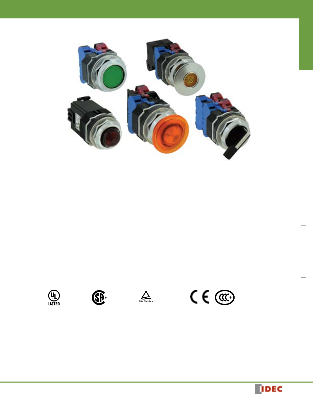
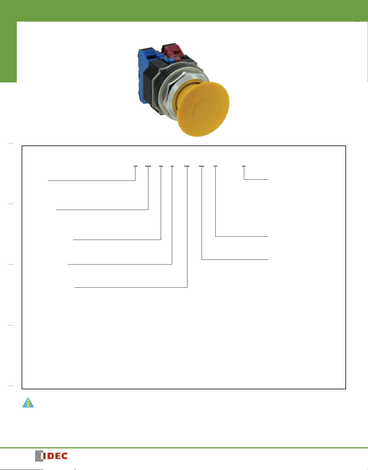
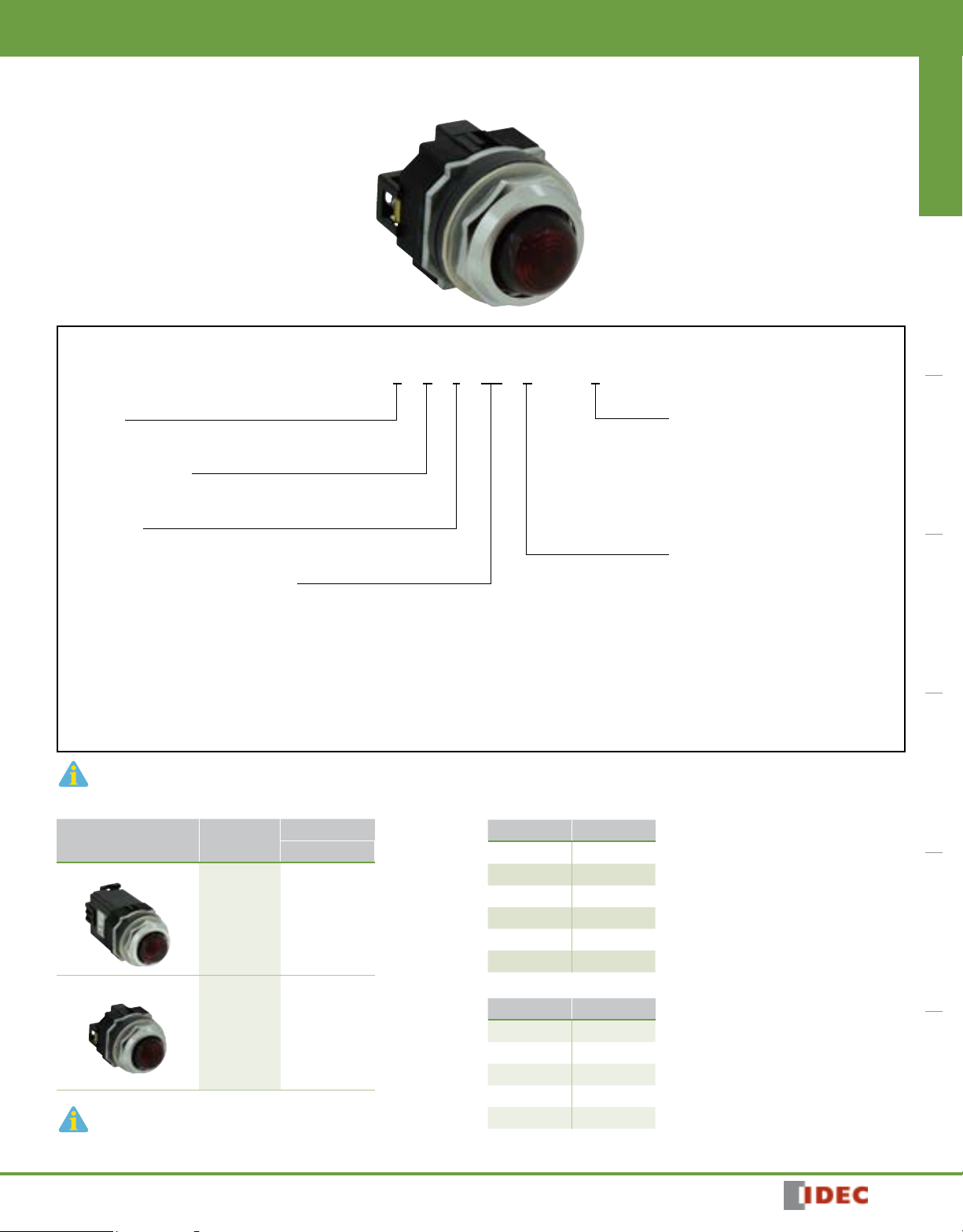
New TWND Series — Full Size NEMA Pushbuttons
ø30mm - TWND Series
Switches & Pilot Devices Signaling Lights Relays & Sockets Timers Contactors Terminal Blocks Circuit Breakers
New! TWND Series: Heavy duty switches built to last
Key features:
• Variety of button sizes up to 2 9/16” (65mm)
• Rugged construction includes chrome plated zinc locking ring die cast
zinc mounting thread
• LED illumination
• Transformer or full voltage
• Slow make, double break wiping contacts
• Modular construction for maximum flexibility
• Available assembled or as sub-components
• UL Type 4X, 13 and IP65 watertight/oiltight panel
UL Listed
File No. E68961
File No. LR21451
The rugged series of TWND switches offers both variety and durability in an
attractive design.
With button sizes up to 2 9/16” (65mm), chrome plated zinc locking rings, die
cast zinc mounting threads, steel anti-rotation rings, and self cleaning contacts,
the TWNDs are here to stay.
The TWND series also offers LED illumination in full voltage and
transformer models.
Regardless of your switching needs, the NEW TWND series provides the kind of
long lasting, industrial strength quality you’ve come to expect from IDEC.
R 50363567
Certificate No.
2016010305902410
1904041136
745
Page 2
ø30mm - TWND Series
Switches & Pilot Devices
Specifications
Conforming to Standards EN60947-5-1, UL508, CSA C22-2 No.14
CSA: pushbuttons and selector switches: A600 pilot lights and illuminated pushbuttons, direct supply pilot lights and illuminated pushbuttons with integral transformer (100/110, 115, 120, 200/220, 230, 240, 380, 400/440, 480V)
Approvals
Switches & Pilot DevicesSignaling LightsRelays & SocketsTimersContactorsTerminal BlocksCircuit Breakers
Operating Temperature
UL: pushbuttons and selector switches: A600 pilot lights and illuminated pushbuttons, direct supply pilot lights and illuminated pushbuttons
with integral transformer (100/110, 115, 120, 200/220, 230, 240, 380, 400/440, 480V)
TÜV: pushbuttons and selector switches: A600 pilot lights and illuminated pushbuttons, direct supply pilot lights and illuminated pushbuttons with integral transformer (100/110, 115, 120, 200/220, 230, 240, 380, 400/440, 480V)
Operation: –25 to +50°C (illuminated versions) -25 ~ +70C non-illuminated
Storage: –40 to +80°C (without freezing) C-> °C
Vibration Resistance 5 to 55Hz, 98m/sec2 (10g) conforming to IEC60068-2-6
Shock Resistance 980m/sec2 (100g) conforming to IEC60068-2-27
Electric Shock Protection Class 2 conforming to IEC60664-1
Degree of Protection
Mechanical Life
Pollution Degree
(conforming to IEC60947-1)
IP65 (from front of the panel) (conforming to IEC60529)
UL Type 1, 2, 3, 3R, 3S, 4, 4X, 5, 12, 13 (conforming to NEMA ICS6-110)
Momentary pushbuttons: 5,000,000 (1800 operations per hour)
All other switches: 500,000
3
Mechanical-Electrical Specifications
Rated Operational Characteristics AC-15: A600
Rated Insulation Voltage 600V
Rated Impulse Withstanding Voltage
øDielectric Strength
Rated Thermal Current 10 Amp
Minimum Switching Capacity 5 mA at 3V AC/DC (applicable range may vary with operating conditions and load types)
Contact Operation Slow break NC or NO
Operating Force
Recommended Terminal Torque
Applicable Wire Size Pilot Light
Between live and dead metal parts
2.5kV AC, 1 minute
Flush and extended pushbuttons—with 1NO or 1NC contact: 6.2±2N (momentary), 9.0±1.5N
Additional contacts—1NO or 1NC: +3.0N
Unit Wire Number of Wires
Crimping Terminal 2 1.0 to 1.3
HW-U Contact Block
Illuminated Unit (*1)
1. * refers to the lamp terminals of the illuminated push buttons and selector switches.
Solid Wire
Stranded Wire
Stranded Wire 0.3 to 2.0 mm (AWG14 to 22)
Solid Wire ø0.5 to 1.6 mm (AWG14 to 22)
Stranded Wire ø0.3 to 2.0 mm (AWG14 to 22)
ø0.5 to 1.6 mm (AWG14 to 22) 2 1.0 to 1.3
ø1.7 to 2.0 mm (AWG12) 1 1.2 to 1.3
2
0.3 to 2.0 mm
Crimping Terminal
Crimping Terminal
(AWG14 to 22) 2 1.0 to 1.3
2.1 to 3.5 mm2 (AWG12) 1 1.2 to 1.3
Recommended Tightening
Torque (Nm)
2 1.0 to 1.3 M3.5Solid Wire ø0.5 to 1.6 mm (AWG14 to 22)
2
0.6 to 1.0 (M3.0)
1.0 to 1.3 (M3.5)
Terminal Screw
M3.5
Contact Resistance Initial contact resistance of 50mΩ or less
Contact Gap
LED Ratings LEDs: 6V: 8mA, 12V: 11mA, 24V: 11mA, 120V: 8.8mA, 240V: 8.6mA
Contact Material Silver
4mm (NO and NC)
2mm (NO-EM and NC-LB)
Contact Ratings
Contact Ratings by Utilization Category IEC 60947-5-1
Contact Ratings by Utilization Category
Operational Voltage 24V 48V 50V 110V 220V 440V
AC 50/60 Hz
Operation Current
DC
AC-12 Control of resistive loads & solid state loads 10A — 10A 10A 6A 2A
AC-15 Control of electromagnetic loads (> 72VA) 10A — 7A 5A 3A 1A
DC-12 Control of resistive loads & solid state loads 10A 5A — 2.2A 1.1A —
DC-13 Control of electromagnets 5A 2A — 1.1A 0.6A —
AC-15 (A600)
DC-13 (P600)
746
1904041136
Page 3
•
Switches & Pilot Devices
Non-Illuminated Pushbuttons (Assembled)
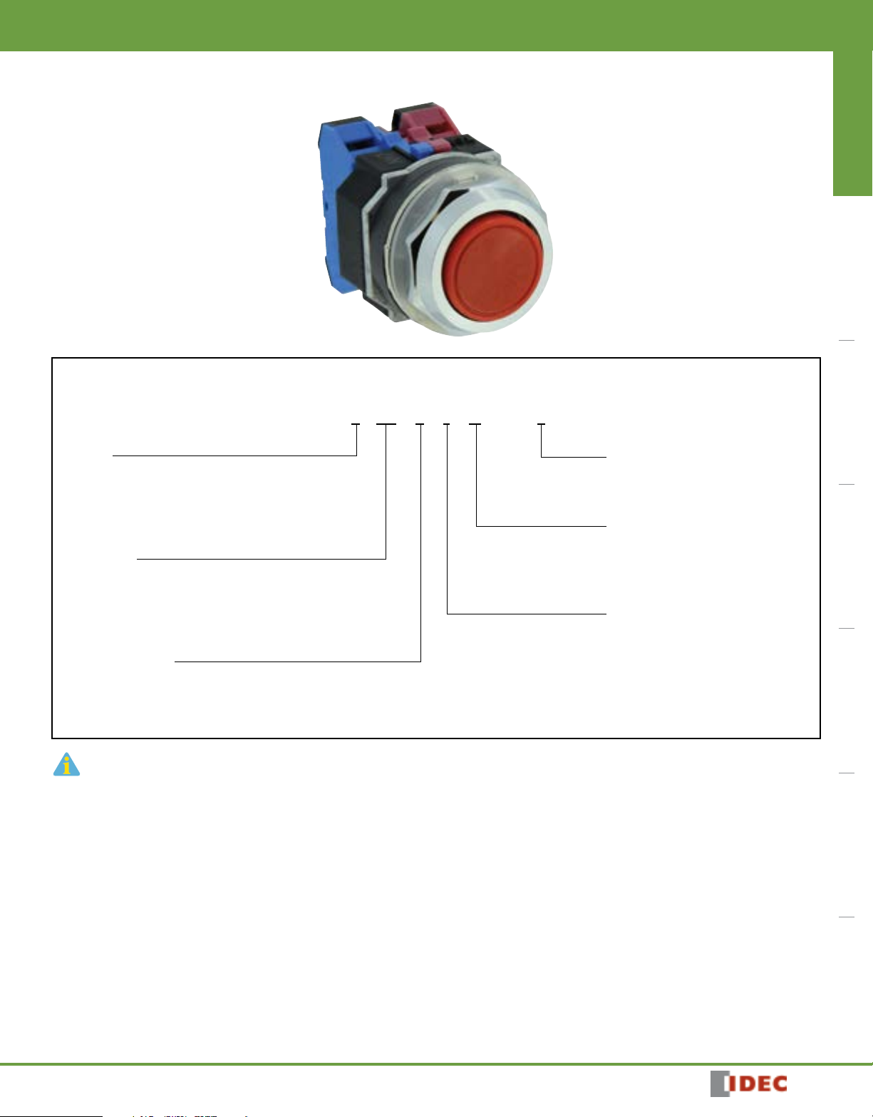
Assembled Pushbuttons
A B ( ) D 1 10 NU R
ø30mm - TWND Series
Switches & Pilot Devices Signaling Lights Relays & Sockets Timers Contactors Terminal Blocks Circuit Breakers
Function
B: Momentary
O: Maintained
V: Pushlock Turn Reset
Y: Push-Pull
Bezel Shape
Blank: Octagonal
F: Full Shroud
G: Mushroom Shroud
P: Neoprene Boot
Series Designation
D: TWND Series
1. Use only when interpreting part numbers. Do not use for developing part numbers.
2. Custom contact configurations available, contact IDEC for details.
Button Color
B: Black G: Green W: White
R: Red S: Blue Y: Yellow
Contact Arrangement
10: 1NO 01: 1NC
20: 2NO 02: 2NC
11: 1NO-1NC 22: 2NO-2NC
Button Shape
1: Flush
2: Extended
3: Mushroom ø 40mm
4: Jumbo Mushroom ø 65mm
1904041136
747
Page 4
ø30mm - TWND Series
Switches & Pilot Devices
Non-Illuminated Pushbuttons (Assembled)
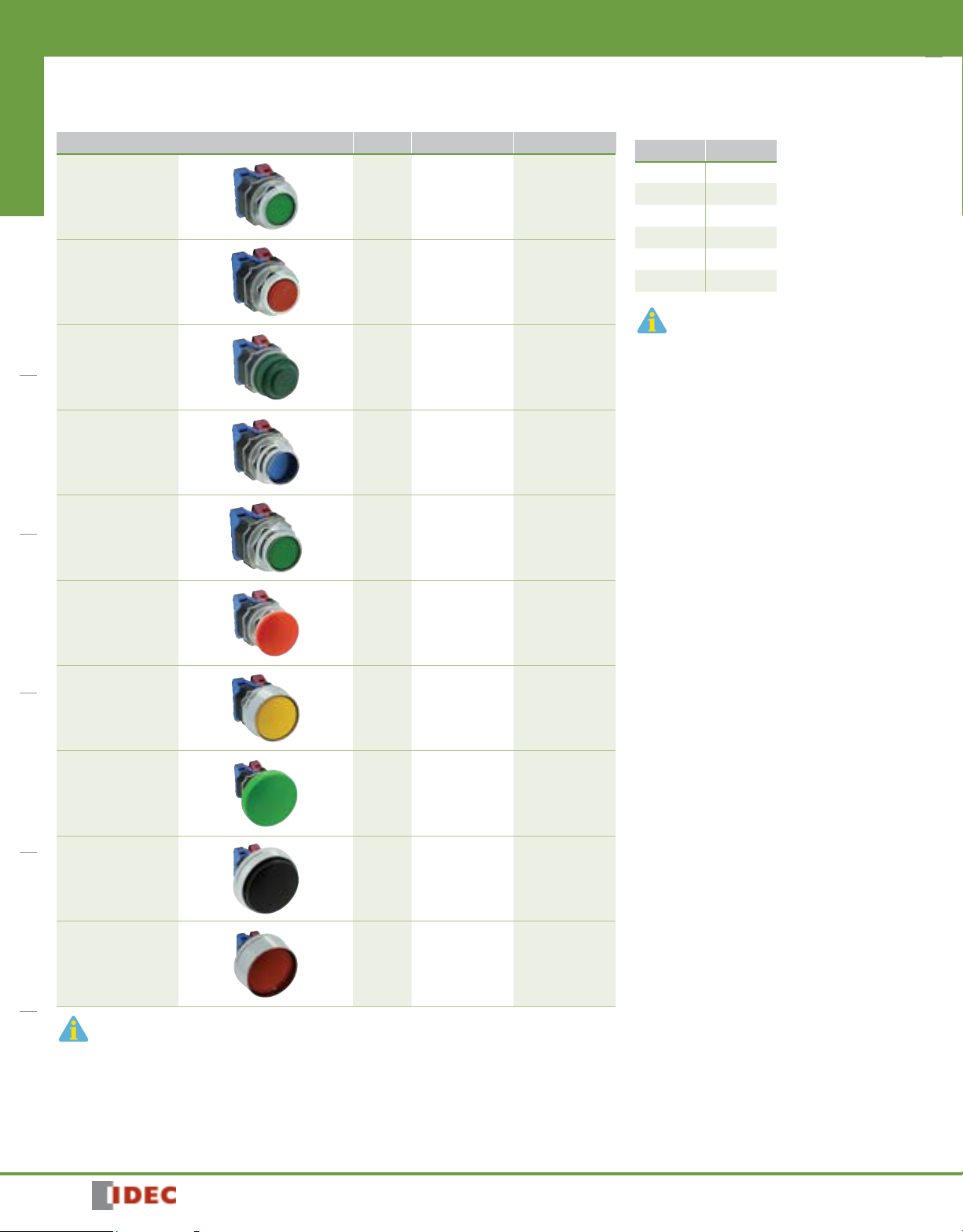
Non-Illuminated Pushbuttons
Flush
Switches & Pilot DevicesSignaling LightsRelays & SocketsTimersContactorsTerminal BlocksCircuit Breakers
Extended
Extended with
Neoprene Boot
Recessed
Extended with
Full Shroud
ø 40mm
Mushroom Head
ø 40mm
Mushroom Head
with Full Shroud
ø 65mm
Jumbo Mushroom Head
ø 65mm
Jumbo Mushroom Head
with Shallow Shroud
ø 65mm
Jumbo Mushroom Head
With Deep Shroud
†
1. In place of j, specify the Button Color Code.
2. For sub-assembly part numbers, see next page.
4. †Neoprene boot available only in Black (B), Green (G), Red (R) and Yellow (Y).
Style Contacts Momentary Maintained
1NO
1NC
1NO-1NC
2NO
2NC
1NO
1NC
1NO-1NC
2NO
2NC
1NO
1NC
1NO-1NC
2NO
2NC
1NO
1NC
1NO-1NC
2NO
2NC
1NO
1NC
1NO-1NC
2NO
2NC
1NO
1NC
1NO-1NC
2NO
2NC
1NO
1NC
1NO-1NC
2NO
2NC
1NO
1NC
1NO-1NC
2NO
2NC
1NO
1NC
1NO-1NC
2NO
2NC
1NO
1NC
1NO-1NC
2NO
2NC
ABD110NUj
ABD101NUj
ABD111NUj
ABD120NUj
ABD102NUj
ABD210NUj
ABD201NUj
ABD211NUj
ABD220NUj
ABD202NUj
ABPD210NUj
ABPD201NUj
ABPD211NUj
ABPD220NUj
ABPD202NUj
ABFD110NUj
ABFD101NUj
ABFD111NUj
ABFD120NUj
ABFD102NUj
ABFD210NUj
ABFD201NUj
ABFD211NUj
ABFD220NUj
ABFD202NUj
ABD310NUj
ABD301NUj
ABD311NUj
ABD320NUj
ABD302NUj
ABGD310NUj
ABGD301NUj
ABGD311NUj
ABGD320NUj
ABGD302NUj
ABD410NUj
ABD401NUj
ABD411NUj
ABD420NUj
ABD402NUj
ABGD410NUj
ABGD401NUj
ABGD411NUj
ABGD420NUj
ABGD402NUj
ABFD410NUj
ABFD401NUj
ABFD411NUj
ABFD420NUj
ABFD402NUj
AOD110NUj
AOD101NUj
AOD111NUj
AOD120NUj
AOD102NUj
AOD210NUj
AOD201NUj
AOD211NUj
AOD220NUj
AOD202NUj
AOPD210NUj
AOPD201NUj
AOPD211NUj
AOPD220NUj
AOPD202NUj
AOFD110NUj
AOFD101NUj
AOFD111NUj
AOFD120NUj
AOFD102NUj
AOFD210NUj
AOFD201NUj
AOFD211NUj
AOFD220NUj
AOFD202NUj
AOD310NUj
AOD301NUj
AOD311NUj
AOD320NUj
AOD302NUj
AOGD310NUj
AOGD301NUj
AOGD311NUj
AOGD320NUj
AOGD302NUj
AOD410NUj
AOD401NUj
AOD411NUj
AOD420NUj
AOD402NUj
AOGD410NUj
AOGD401NUj
AOGD411NUj
AOGD420NUj
AOGD402NUj
AOFD410NUj
AOFD401NUj
AOFD411NUj
AOFD420NUj
AOFD402NUj
j Button Color Codes
Color Code
Black B
Green G
Red R
Blue S
Yellow Y
White W
1. 65mm Jumbo mushroom not available in white.
2. Neoprene boot is not available in blue or white.
748
1904041136
Page 5
•
Switches & Pilot Devices
ø30mm - TWND Series
Non-Illuminated Pushbuttons (Sub-Assembled)
Contact Block + Operator + Button = Complete Part
Switches & Pilot Devices Signaling Lights Relays & Sockets Timers Contactors Terminal Blocks Circuit Breakers
Operators
Flush/Extended
Extended with
Full Shroud
ø 40mm Mushroom/ø
65mm Jumbo
Mushroom
ø 40mm Mushroom
with Full Shroud
Style
Part Number
Momentary Maintained
ABD1200T8 AOD1200T8
ALFD2300T8 AOLFD2300T8
ABD3400T8 AOD3400T8
ABGD-300T AOGD-300T
Buttons and Lenses
Flush
Extended
ø 40mm Mushroom
ø 65mm Jumbo
Mushroom
Style Part Number
ABD1BN-j
ABD2BN-j
ABD3BN-j
ABD4BN-j
1904041136
ø 65mm Jumbo
Mushroom with
Shallow Shroud
ø 65mm Jumbo
Mushroom with
Deep Shroud
ABGD-400T AOGD-400T
ABFD-400T AOFD-400T
In place of j, specify the Button Color Code. (See table previous page)
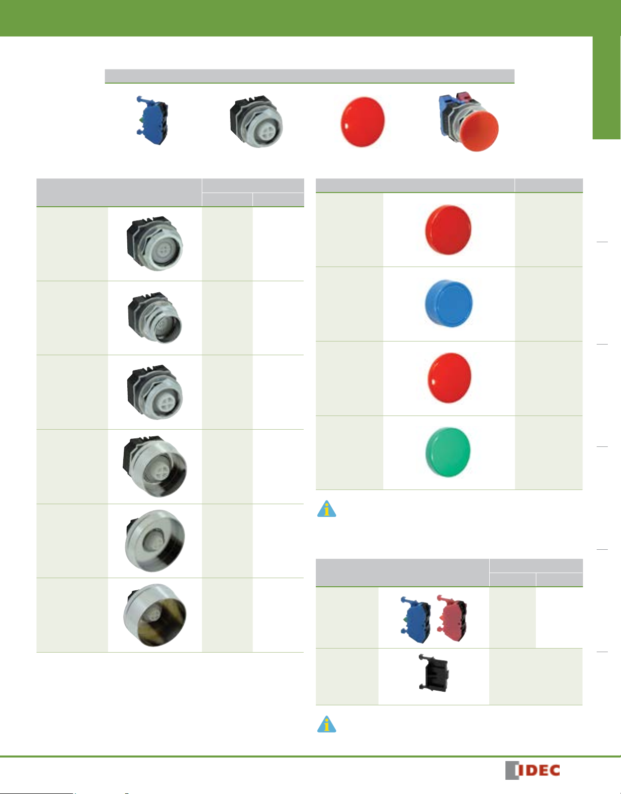
Contact Blocks
Style
All Control Units
Dummy Block
1. Dummy blocks (no contacts) are used with an odd number of contact blocks.
2. Combining HW-U10R-F and HW-U01R-F result in overlapping contacts (remain on, or
closed, when switch is moved between two positions).
1NO 1NC
HW-U10-F
HW-U10R-F
(early make)
Part Number
HW-U01-F
HW-U01R-F
(late break)
HW-DB
749
Page 6
ø30mm - TWND Series
Switches & Pilot DevicesSignaling LightsRelays & SocketsTimersContactorsTerminal BlocksCircuit Breakers
Switches & Pilot Devices
Stop Switches (Assembled)
Assembled Stop Switches
A V (L) D 3 22 11 D NU R
Function
V: Pushlock Turn Reset
Y: Push-Pull
Illumination
Blank: None
L: Illuminated
Series Designation
D: TWND Series
Button/Lens Size
3: 40mm Mushroom
Illumination Circuit
Full Voltage:
66: 6VAC/DC
11: 12VAC/DC
22: 24AC/DC
QH2: 120VAC
QM4: 240VAC
Transformer:
126: 120VAC step down transformer
246: 240VAC step down transformer
486: 480VAC step down transformer
Button/Lens Color Code
A: Amber
G: Green
R: Red
S: Blue
W: White
Y: Yellow
(illuminated units only)
D: LED
Contact Arrangement
10: 1NO 01: 1NC
20: 2NO 02: 2NC
11: 1NO-1NC 22: 2NO-2NC
1. Use only when interpreting part numbers. Do not use for developing part numbers.
2. Custom contact configurations available, contact IDEC for details.
750
1904041136
Page 7
•
Switches & Pilot Devices
Stop Switches (Assembled)
ø30mm - TWND Series
Switches & Pilot Devices Signaling Lights Relays & Sockets Timers Contactors Terminal Blocks Circuit Breakers
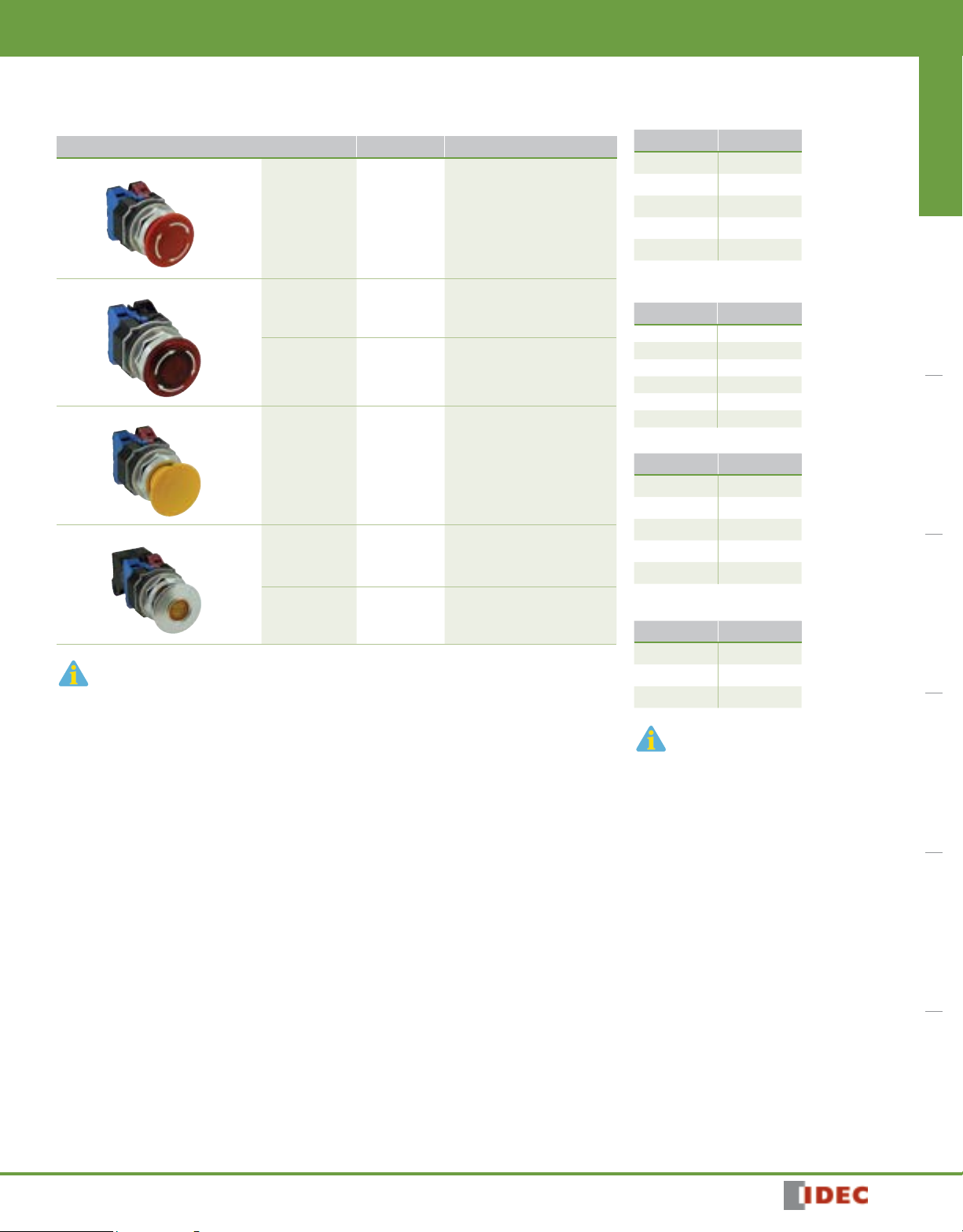
Stop Switches
Style Contacts Part Number
ø 40mm Pushlock Turn Reset
ø 40mm Illuminated Pushlock Turn Reset
ø 40mm Push-Pull
ø 40mm Illuminated Push-Pull
Non-Illuminated
Full Voltage
Transformer
Non-Illuminated
Full Voltage
1NO
1NC
1NO-1NC
2NO
2NC
1NO-1NC
2NO
2NC
1NO-1NC
2NO
2NC
1NO
1NC
1NO-1NC
2NO
2NC
1NO-1NC
2NO
2NC
AVD310NUR*
AVD301NUR*
AVD311NUR*
AVD320NUR*
AVD302NUR*
AVLD3l11DNUR*
AVLD3l20DNUR*
AVLD3l02DNUR*
AVLD3 m 11DNUR*
AVLD3 m 20DNUR*
AVLD3 m 02DNUR*
AYD310NUj
AYD301NUj
AYD311NUj
AYD320NUj
AYD302NUj
AYLD3l11DNUk **
AYLD3l20DNUk **
AYLD3l02DNUk **
j Button Color Codes
Color Code
Black B
Green G
Red R
Blue S
Yellow Y
k Lens Color Codes
Color Code
Amber A
Green G
Red R
Blue S
White W
Yellow Y
l Full Voltage Codes
Voltage Code
6V AC/DC 66
12V AC/DC 11
24V AC/DC 22
120V AC QH2
240V AC QM4
Transformer
1. In place of j, specify the button color code
2. In place of k, specify the lens color code.
3. In place of l, specify the Full Voltage (lamp voltage) Code.
4. * Only available in red.
5. In place of m, specify the transformer voltage code.
6. **Not available in blue.
7. For sub-assembly part numbers, see next page.
8. For nameplates and accessories, see page 769 and page 767.
9. For dimensions, see page 772.
1NO-1NC
2NO
2NC
AYLD3 m 11DNUk **
AYLD3 m 20DNUk **
AYLD3 m 02DNUk **
m
Transformer Voltage Codes
Voltage Code
120VAC 126
240VAC 246
480VAC 486
Transformers step down to 6V.
1904041136
751
Page 8
ø30mm - TWND Series
Transformer* + Operator + Lamp + Button/Lens = Complete Part
Switches & Pilot DevicesSignaling LightsRelays & SocketsTimersContactorsTerminal BlocksCircuit Breakers
* Not required for full voltage units.
Operators
ø40mm Illuminated and
Non-illuminated
Pushlock Turn Reset
ø 40mm Illuminated and
Non-illuminated Push-Pull
Buttons and Lenses
Button for Pushlock Turn
Reset Stop Switches
(ø40mm, red only)
Switches & Pilot Devices
Stop Switches (Sub-Assembled)
Style Part Number
AVD000T8
AYD000T8
Style Part Number
AVN3B-R
Lamps
Style Voltage Part Number
LED
1. In place of k, specify the LED color code.
2. The LED contains a current-limiting resistor
6V AC/DC
12V AC/DC
24V AC/DC
120V AC
240V AC
and a protection diode.
j Button Color Codes
Color Code
Black B
Green G
Red R
Blue S
Yellow Y
LSTD-6l
LSTD-1l
LSTD-2l
LSTD-H2l
LSTD-M4l
k Lens Color Codes
Color Code
Amber A
Green G
Red R
Blue S
White W
l LED Color Codes
Color Code
Amber A
Green G
Red R
Blue S
White W
Lens for Illuminated Pushlock
Turn Reset Stop Switches
(ø40mm, red only)
Button for Push-Pull Stop
Switches (ø40mm)
Lens for Illuminated Push-Pull
Stop Switches
(ø40mm)
1. In place of j, specify the Button Color Code. (See table below)
2. In place of k, specify the LED Color Code.
3. *Not available in blue.
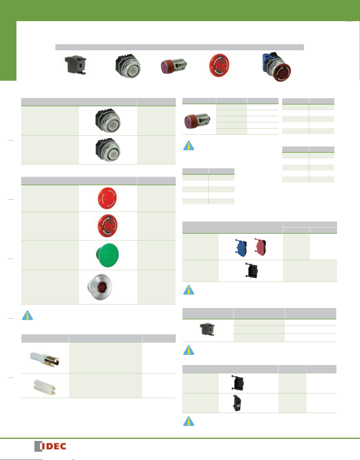
Lamp Circuit Components
Style Application Part Number
Long Lamp Holder
Used with Full-size Transformer and
two contact blocks
Used with Full Voltage Adaptor and
two contact blocks
Lead Holder
Used with TW-LH2 holder when using
four contact blocks
2 pos*
AVLN3LU-R
AYD3BN-j
AYLD3L-k
TW-LH2
HW-LH3
Contact Blocks
Style
All Control Units
Dummy Block
1. Dummy blocks (no contacts) are used with an odd number of contact blocks.
2. Combining HW-U10R-F and HW-U01R-F result in overlapping contacts.
Transformers
Style
6V secondary voltage (uses 6V LED).
Primary Voltage
(50/60Hz)
120V AC TW-F126B
240V AC TW-F246B
480V AC HW-L486
Full Voltage Modules
Style Description Part Number
Dummy Block with
Full Voltage Adaptor
Full Voltage Adaptor
All Transformers step down to 6V (use 6V lamp).
For use with
odd number
of contacts.
For use with
even number
of contacts.
Finger-Safe HW-DA1FBN
Finger-Safe TW-DA1FB
Part Number
1NO 1NC
HW-U10-F
HW-U10R-F
(early make)
HW-DB
Part Number
HW-U01-F
HW-U01R-F
(late break)
752
1904041136
Page 9
•
Switches & Pilot Devices
Pilot Lights (Assembled)
Assembled Pilot Lights
A P D 1 126 D NU R
ø30mm - TWND Series
Switches & Pilot Devices Signaling Lights Relays & Sockets Timers Contactors Terminal Blocks Circuit Breakers
Function
P: Pilot Light
Series Designation
D: TWND Series
Lens Shape
1: Dome
Rated Operational Voltage (Primary)
Transformer Type
126: 120V AC
246: 240V AC
486: 480V AC
Use only when interpreting part numbers. Do not use for developing part numbers.
Full Voltage Type
66: 6VAC/DC
11: 12VAC/DC
22: 24VAC/DC
QH2: 120VAC
QM4: 240VAC
LED Pilot Lights
Style
Transformer Dome
Full Voltage Dome
1. In place of k, specify the Lens/LED Color Code.
2. In place of l, specify the Full Voltage Code (LED voltage).
3. Yellow pilot light comes with white LED.
Operating
Voltage
120V AC
240V AC
480V AC
—
Part Number
LED
APD1126DNUk
APD1246DNUk
APD1486DNUk
APD1lDNUk
Lens Color Code
A: Amber
G: Green
R: Red
S: Blue
W: White
Y: Yellow
D: LED
k Lens Color Codes
Color Code
Amber A
Green G
Red R
Blue S
White W
Yellow Y
l Full Voltage Codes
Voltage Code
6V AC/DC 66
12V AC/DC 11
24V AC/DC 22
120V AC QH2
240V AC QM4
1904041136
753
Page 10

ø30mm - TWND Series
Transformer* + Operator + Lamp + Lens = Complete Part
Switches & Pilot DevicesSignaling LightsRelays & SocketsTimersContactorsTerminal BlocksCircuit Breakers
* Not required for full voltage units.
One Each from Left Column plus One Selection from Right Column
Operators
Switches & Pilot Devices
Pilot Lights (Sub-Assembled)
Full Voltage Clips
Style Part Number
Transformer or
FULL Voltage
Lenses
Style Part Number
Dome Lens
1. In place of k, specify the Lens Color Code.
Lamps
Style Voltage Part Number
LED
6V AC/DC
12V AC/DC
24V AC/DC
120V AC
240V AC
APD09ST8
APN106LN-k
LSTD-6l
LSTD-1l
LSTD-2l
LSTD-H2l
LSTD-M4l
Primary Voltage (50/60Hz) Part Number
Required for all full voltage models. Two pieces each.
2 clips required for full voltage pilot lights
Transformers (only for Pilot Lights)
Style
LED
6V secondary voltage (use 6V lamp).
k Lens Color Codes
Color Code
Amber A
Green G
Red R
Blue S
White W
Yellow Y
Primary Voltage
(50/60Hz)
l LED Color Codes
APD-F
Part Number
120V AC TWD-0126
240V AC TWD-0246
480V AC TWD-0486
Color Code
Amber A
Green G
Red R
Blue S
White W
Yellow LED not available, use
white LED with Yellow lens.
1. In place of k, specify the LED color code.
2. The LED contains a current-limiting resistor and a protection diode.
754
1904041136
Page 11

•
Switches & Pilot Devices
Illuminated Pushbuttons (Assembled)
Assembled Illuminated Pushbuttons
ø30mm - TWND Series
Switches & Pilot Devices Signaling Lights Relays & Sockets Timers Contactors Terminal Blocks Circuit Breakers
Function
L: Momentary Action
OL: Maintained Action
Bezel Shape
Blank: Octagonal
F: Full Shroud
Series Designation
D: TWND Series
Lens Shape
2: Extended
3: Mushroom ø 40mm
Rated Operational Voltage (Primary)
Transformer Type
126: 120V AC
246: 240V AC
486: 480V AC
Full Voltage Type
66: 6VAC/DC
11: 12VAC/DC
22: 24VAC/DC
QH2: 120VAC
QM4: 240VAC
A L ( ) D 2 126 11 D NU R
Lens Color Code
A: Amber
G: Green
R: Red
S: Blue
W: White
Y: Yellow
D: LED
Contact Arrangement
20: 2NO 02: 2NC
11: 1NO-1NC
1904041136
1. Use only when interpreting part numbers. Do not use for developing part numbers.
2. All transformers step down to 6V.
755
Page 12

ø30mm - TWND Series
Switches & Pilot Devices
Illuminated Pushbuttons (Assembled)
Illuminated Pushbuttons
Switches & Pilot DevicesSignaling LightsRelays & SocketsTimersContactorsTerminal BlocksCircuit Breakers
Extended Lens
Extended Lens with Full Shroud
ø 40mm Mushroom Lens
Style Contacts
Full Voltage
Transformer
Full Voltage
Transformer
Full Voltage
1NO-1NC
2NO
2NC
1NO-1NC
2NO
2NC
1NO-1NC
2NO
2NC
1NO-1NC
2NO
2NC
1NO-1NC
2NO
2NC
Part Number
Momentary Maintained
ALD2l11DNUk
ALD2l20DNUk
ALD2l02DNUk
ALD2 m 11DNUk
ALD2 m 20DNUk
ALD2 m 02DNUk
ALFD2l11DNUk
ALFD2l20DNUk
ALFD2l02DNUk
ALFD2 m 11DNUk
ALFD2 m 20DNUk
ALFD2 m 02DNUk
ALD3l11DNUk
ALD3l20DNUk
ALD3l02DNUk
AOLD2l11DNUk
AOLD2l20DNUk
AOLD2l02DNUk
AOLD2 m 11DNUk
AOLD2 m 20DNUk
AOLD2 m 02DNUk
AOLFD2l11DNUk
AOLFD2l20DNUk
AOLFD2l02DNUk
AOLFD2 m 11DNUk
AOLFD2 m 20DNUk
AOLFD2 m 02DNUk
AOLD3l11DNUk
AOLD3l20DNUk
AOLD3l02DNUk
k Lens Color Codes
Color Code
Amber A
Green G
Red R
Blue S
White W
Yellow Y
l Full Voltage Codes
Voltage Code
6V AC/DC 66
12V AC/DC 11
24V AC/DC 22
120V AC QH2
240V AC QM4
m Transformer Voltage Codes
Voltage Code
120VAC 126
240VAC 246
480VAC 486
6V secondary voltage
(uses 6V LED).
Transformer
1NO-1NC
1. In place of k, specify the Lens Color Code.
2. In place of l, specify the Full Voltage Code (LED voltage).
3. In place of m, specify the Transformer Voltage Code.
4. Light is independent of switch position.
5. Yellow pushbutton comes with white LED only.
2NO
2NC
ALD3 m 11DNUk
ALD3 m 20DNUk
ALD3 m 02DNUk
AOLD3 m 11DNUk
AOLD3 m 20DNUk
AOLD3 m 02DNUk
756
1904041136
Page 13

•
Switches & Pilot Devices
ø30mm - TWND Series
Illuminated Pushbuttons (Sub-Assembled)
Transformer* + Contact Block + Operator + LED + Lens = Complete Part
*Not required for full voltage types.
Switches & Pilot Devices Signaling Lights Relays & Sockets Timers Contactors Terminal Blocks Circuit Breakers
Operators
Extended
Extended with
Full Shroud
40mm Mushroom
Lenses
Extended
Style
Part Number
Momentary Maintained
ALD2300T8 AOLD2300T8
ALFD2300T8 AOLFD2300T8
ALD2300T8 AOLD2300T8
Style Part Number
ALN06LU-k
Lamps
Style Voltage Part Number
LED
1. In place of k, specify the LED color code.
2. The LED contains a current-limiting resistor
and a protection diode.
6V AC/DC
12V AC/DC
24V AC/DC
120V AC
240V AC
Contact Blocks
Style
All Control Units
LSTD-6l
LSTD-1l
LSTD-2l
LSTD-H2l
LSTD-M4l
k Lens Color Codes
Color Code
Amber A
Green G
Red R
Blue S
White W
Yellow Y
l LED Color Codes
Color Code
Amber A
Green G
Red R
Blue S
White W
Yellow lens only. Yellow
LED not available, use
white LED.
Part Number
1NO 1NC
HW-U10-F
HW-U10R-F
(early make)
HW-U01-F
HW-U01R-F
(late break)
ø 40mm Mushroom
In place of k, specify the Lens Color Code.
Lamp Circuit Components
Style Application Part Number
Long Lamp Holder
Lead Holder
1904041136
Used with Full-size Transformer and
two contact blocks
Used with Full Voltage Adaptor and
two contact blocks
Used with TW-LH2 holder when using
four contact blocks
ALN3LU-k
TW-LH2
HW-LH3
Dummy Block
1. Dummy blocks (no contacts) are used with an odd number of contact blocks.
2. Combining HW-U10R-F and HW-U01R-F result in overlapping contacts (remain on, or
closed, when switch is moved between two positions).
Transformers
Style
Transformers
6V secondary voltage (use 6V LED).
Primary Voltage
(50/60Hz)
120V AC TW-F126B
240V AC TW-F246B
480V AC HW-L486
Full Voltage Modules
Style Description Part Number
Dummy Block with
Full Voltage Adaptor
Full Voltage Adaptor
All Transformers step down to 6V (use 6V lamp).
For use with
odd number
of contacts.
For use with
even number
of contacts.
Finger-Safe HW-DA1FBN
Finger-Safe TW-DA1FB
HW-DB
Part Number
757
Page 14

ø30mm - TWND Series
Switches & Pilot DevicesSignaling LightsRelays & SocketsTimersContactorsTerminal BlocksCircuit Breakers
Switches & Pilot Devices
Non-Illuminated Selector Switches (Assembled)
Assembled Selector Switches
A S D 2 ( ) ( ) 11 NU – ( )
Function
S: Selector Switch
Series Designation
D: TWND Series
Number of Positions
2: 2-Position
3: 3-Position
Spring Return Action
Blank: Maintained
1: Spring return from Right
2: Spring return from Left
3: 2-Way spring return from Left and Right
1. Use only when interpreting part numbers. Do not use for developing part numbers.
2. Custom key removal codes available. Please contact IDEC for details.
Circuit Number
(See Circuit # column of Selector Switch
Contact Arrangement Chart on beginning
on page 764.)
Contact Arrangement Code
10: 1NO 01: 1NC
20: 2NO 02: 2NC
40: 4NO 04: 4NC
11: 1NO-1NC 22: 2NO-2NC
Operator Style Code
Blank: Knob Operator
L: Lever Operator
K: Key Operator
758
1904041136
Page 15

•
Switches & Pilot Devices
L
R
C
C
C
C
Non-Illuminated Selector Switches (Assembled)
Non-Illuminated 2-Position Selector Switches
Style Part Number
Contact
Operator
Position
L
Mounting
R
Maintained
L
ø30mm - TWND Series
Switches & Pilot Devices Signaling Lights Relays & Sockets Timers Contactors Terminal Blocks Circuit Breakers
Spring Return
from Right
R
L
R
Spring Return
from Left
1NO
1NC
1NO
1NC12
2NO
2NC
2NO
2NC
2NO
2NC
1
OOX
2
1
X
2
OOO
O
X
1
O
2
O
1
X
2
X
1
O
2
X
3
O
4
X
1
O
2
O
3
X
4
X
Knob
Lever
O
Knob
Lever
Knob
X
Lever
O
Knob
X
Lever
X
Knob
O
Lever
O
X
Knob
O
Lever
X
O
X
Knob
X
Lever
O
O
Key
Key
Key
Key
Key
Key
Key
ASD210NU
ASD2L10NU
ASD2K10NU
ASD201NU
ASD2L01NU
ASD2K01NU
ASD211NU
ASD2L11NU
ASD2K11NU
ASD220NU
ASD2L20NU
ASD2K20NU
ASD202NU
ASD2L02NU
ASD2K02NU
ASD222NU
ASD2L22NU
ASD2K22NU
ASD222NU-111
ASD2L22NU-111
ASD2K22NU-111
Non-Illuminated 3-Position Selector Switches
Style Part Number
Operator Position Maintained Spring Return from Right Spring Return from Left Spring Return Two-Way
C
R
Knob
O
O
O
X
X
X
O
X
O
O
O
X
X
X
X
O
O
X
X
O
X
O
O
X
X
O
O
X
X
O
O
X
O
O
O
X
O
O
O
X
X
X
O
X
X
X
O
X
Lever
Key
Knob
Lever
Key
Knob
Lever
Key
Knob
Lever
Key
Knob
Lever
Key
Knob
Lever
Key
Knob
Lever
Key
ASD320NU
ASD3L20NU
ASD3K20NU
ASD302NU
ASD3L02NU
ASD3K02NU
ASD322NU
ASD3L22NU
ASD3K22NU
ASD322NU-309
ASD3L22NU-309
ASD3K22NU-309
ASD322NU-310
ASD3L22NU-310
ASD3K22NU-310
ASD340NU
ASD3L40NU
ASD3K40NU
ASD304NU
ASD3L04NU
ASD3K04NU
2NO
2NC
2NO
2NC
2NO
2NC
2NO
2NC
4NO
4NC
Contact
Mounting
1
2
1
2
1
2
3
4
1
2
3
4
1
2
3
4
1
2
3
4
1
2
3
4
L
X
O
O
X
X
O
O
X
X
X
O
O
O
O
O
O
X
O
X
O
O
X
O
X
ASD2110NU
ASD21L10NU
ASD21K10NU
ASD2101NU
ASD21L01NU
ASD21K01NU
ASD2111NU
ASD21L11NU
ASD21K11NU
ASD2120NU
ASD21L20NU
ASD21K20NU
ASD2102NU
ASD21L02NU
ASD21K02NU
ASD2122NU
ASD21L22NU
ASD21K22NU
ASD2122NU-111
ASD21L22NU-111
ASD21K22NU-111
L
ASD2210NU
ASD22L10NU
ASD22K10NU
ASD2201NU
ASD22L01NU
ASD22K01NU
ASD2211NU
ASD22L11NU
ASD22K11NU
ASD2220NU
ASD22L20NU
ASD22K20NU
ASD2202NU
ASD22L02NU
ASD22K02NU
ASD2222NU
ASD22L22NU
ASD22K22NU
ASD2222NU-111
ASD22L22NU-111
ASD22K22NU-111
R
L
ASD3120NU
ASD31L20NU
ASD31K20NU
ASD3102NU
ASD31L02NU
ASD31K02NU
ASD3122NU
ASD31L22NU
ASD31K22NU
ASD3122NU-309
ASD31L22NU-309
ASD31K22NU-309
ASD3122NU-310
ASD31L22NU-310
ASD31K22NU-310
ASD3140NU
ASD31L40NU
ASD31K40NU
ASD3104NU
ASD31L04NU
ASD31K04NU
R
ASD3220NU
ASD32L20NU
ASD32K20NU
ASD3202NU
ASD32L02NU
ASD32K02NU
ASD3222NU
ASD32L22NU
ASD32K22NU
ASD3222NU-309
ASD32L22NU-309
ASD32K22NU-309
ASD3222NU-310
ASD32L22NU-310
ASD32K22NU-310
ASD3240NU
ASD32L40NU
ASD32K40NU
ASD3204NU
ASD32L04NU
ASD32K04NU
1. The truth table indicates the operating position of
contact block when the operator is switched to that
position.
X = On (closed contacts) O = Off (open contacts)
X X
= Overlapping Contacts: Remain on (closed
contacts) when switch is moved between these two
positions.
2. All knob and lever selector switches come in black.
Other colors are available by ordering the knob or lever
separately.
3. Custom contact arrangements available, see page 764.
L
R
L
R
ASD3320NU
ASD33L20NU
ASD33K20NU
ASD3302NU
ASD33L02NU
ASD33K02NU
ASD3322NU
ASD33L22NU
ASD33K22NU
ASD3322NU-309
ASD33L22NU-309
ASD33K22NU-309
ASD3322NU-310
ASD33L22NU-310
ASD33K22NU-310
ASD3340NU
ASD33L40NU
ASD33K40NU
ASD3304NU
ASD33L04NU
ASD33K04NU
1904041136
759
Page 16

ø30mm - TWND Series
Switches & Pilot Devices
Non-Illuminated Selector Switches (Sub-Assembled)
Switches & Pilot DevicesSignaling LightsRelays & SocketsTimersContactorsTerminal BlocksCircuit Breakers
Operators
Style Position Description Part Number
Knob/Lever
Key
1. Order knobs, levers, color inserts separately (see below).
2. For key switches, keys are removable in all maintained positions. Other options available,
contact IDEC for details.
3. See page 766 “Operator Truth Tables” for details of difference between cams.
j Color Codes
Knob/Lever Color Code
Black B
Blue S
Green G
Red R
Yellow Y
White W
Contact Blocks + Operator + Knob or Lever* + Color Insert* = Complete Part
1. *Not needed with key type switches.
2. †Knob type shown.
Handles and Inserts
Style Part Number
Maintained ASD0201T8
2
Spring return from right ASD0213T8
Spring return from left ASD0224T8
Maintained, Cam 1
Maintained, Cam 2
Spring return from right, Cam 1
Spring return from right, Cam 2
3
Spring return from left, Cam 1
Spring return from left, Cam 2
Spring return from left/right, Cam 1
Spring return from left/right, Cam 2
Maintained ASD0201KT8
2
Spring return from right ASD0213KT8
Spring return from left ASD0224KT8
Maintained, Cam 1
Maintained, Cam 2
Spring return from right, Cam 1
Spring return from right, Cam 2
3
Spring return from left, Cam 1
Spring return from left, Cam 2
Spring return from left/right, Cam 1
Spring return from left/right, Cam 2
ASD0302T8
ASD0306T8
ASD0314T8
ASD0310T8
ASD0323T8
ASD0328T8
ASD0335T8
ASD0339T8
ASD0302KT8
ASD0306KT8
ASD0302KT8B
ASD0310KT8B
ASD0323KT8
ASD0310KT8B
ASD0335KT8
ASD3K339KT8
Knob
Lever
Color Insert
1. In place of j, specify the Color Code.
*Not available in yellow.
ASDHHY-j
ASDHHL-j*
TW-HC1-j
Contact Blocks
Style
HW-U10-F
All Control Units
Dummy Block
1. Dummy blocks (no contacts) are used with an odd number of contact blocks.
2. Combining HW-U10R-F and HW-U01R-F result in overlapping contacts (remain on, or
closed, when switch is moved between two positions).
HW-U10R-F
(early make)
†
Part Number
1NO 1NC
HW-U01-F
HW-U01R-F
(late break)
HW-DB
1. Knob/Lever not available in white.
2. Color inserts not available in Black.
3. Lever not available in yellow.
760
1904041136
Page 17

•
Switches & Pilot Devices
ø30mm - TWND Series
Function
SL: Illuminated Selector Switch
Series Designation
D: TWND series
Number of Positions
2: 2-Position
3: 3-Position
Spring Return Action
Blank: Maintained
1: Spring return from Right
2: Spring return from Left
3: Two-Way spring return from Left and Right
Illuminated Selector Switches (Assembled)
Switches & Pilot Devices Signaling Lights Relays & Sockets Timers Contactors Terminal Blocks Circuit Breakers
Assembled Illuminated Selector Switches
A SL D 2 (2) 22 11 DN U – 111 – R
Lens Color Code
A: Amber
G: Green
R: Red
S: Blue
W: White
Y: Yellow
Circuit Code Number
See Circuit # column of Selector Switch Contact Arrangement
Charts on page 764.
D: LED Lamp
Rated Operational Voltage (Primary)
Transformer Type
136: 120V AC
256: 240V AC
486: 480V AC
Full Voltage Type
66: 6VAC/DC
11: 12VAC/DC
22: 24VAC/DC
QH2: 120VAC
QM4: 240VAC
Contact Arrangement Code
20: 2NO 02: 2NC
40: 4NO 04: 4NC
11: 1NO-1NC 22: 2NO-2NC
Use only when interpreting part numbers. Do not use for developing part numbers.
1904041136
761
Page 18

ø30mm - TWND Series
R
C
C
C
C
Switches & Pilot Devices
Illuminated Selector Switches (Assembled)
Illuminated 2-Position Selector Switches
Style Part Number
Switches & Pilot DevicesSignaling LightsRelays & SocketsTimersContactorsTerminal BlocksCircuit Breakers
Contact
1NO
1NC12OX
2NO
2NC
2NO
2NC
2NO
2NC
Operator
Position
L R
Mounting
Lamp
Circuit Type
XOTransformer
Full Voltage
12OOXXTransformer
Full Voltage
12X
1
2
3
4
1
2
3
4
X
O
X
O
X
O
O
X
X
OOTransformer
Full Voltage
X
O
Transformer
X
Full Voltage
O
X
X
Transformer
O
Full Voltage
O
Maintained Spring Return from Right
L
R
ASLD2 m11DNUk
ASLD2l11DNUk
ASLD2 m20DNUk
ASLD2l20DNUk
ASLD2 m02DNU-k
ASLD2l02DNU-104-k
ASLD2 m22DNUk
ASLD2l22DNUk
ASLD2 m22DNU-111-k
ASLD2l22DNU-111-k
ASLD21 m11DNUk
ASLD21l11DNUk
ASLD21 m20DNUk
ASLD21l20DNUk
ASLD21 m02DNU-k
ASLD21l02DNU-k
ASLD21 m22DNUk
ASLD21l22DNU
ASLD21 m22DNU-111-k
ASLD21l22DNU-111-k
Illuminated 3-Position Selector Switches, Maintained and Spring Return
Style Part Number
Operator Position
C
Contact
2NO
2NC
2NO
2NC
2NO
2NC
2NO
2NC
4NO
4NC
1. In place of k, specify the Lens/LED Color Code, in place of l, specify the Full Voltage
2. The truth table indicates the operating position of contact block when the operator is
3. Yellow selector switch comes with white LED.
L
Mounting
12X
OOOOX
12O
1
2
3
4
1
2
3
4
1
2
3
4
1
2
3
4
1
2
3
4
(LED voltage) Code, in place of m, specify the Transformer Voltage Code.
switched to that position.
X = On (Closed Contacts) O = Off (Open Contacts)
X X
= Overlapping Contacts: Remain on (closed contacts) when switch is moved
between these positions
X
X
X
X
O
O
O
X
O
X
X
X
O
X
X
O
X
O
O
O
X
O
O
O
X
O
O
X
O
O
O
X
O
O
O
X
O
X
X
X
O
X
X
Lamp
R
Circuit Type
Transformer
Full Voltage
XOTransformer
Full Voltage
O
X
Transformer
X
Full Voltage
O
X
O
Transformer
O
Full Voltage
X
O
X
Transformer
O
Full Voltage
X
O
X
Transformer
O
Full Voltage
X
X
O
Transformer
X
Full Voltage
O
Maintained Spring Return From Right Spring Return from Left Spring Return Two-Way
L
R
ASLD3 m 20DNUk
ASLD3l20DNUk
ASLD3 m 02DNUk
ASLD3l02DNUk
ASLD3 m 22DNUk
ASLD3l22DNUk
ASLD3 m 22DNU-309-k
ASLD3l22DNU-309-k
ASLD3 m 22DNU-310-k
ASLD3l22DNU-310-k
ASLD3 m 40DNUk
ASLD3l40DNUk
ASLD3 m 04DNUk
ASLD3l04DNUk
Spring Return
from Left
L
R
L
ASLD22 m11DNUk
ASLD22l11DNUk
ASLD22 m20DNUk
ASLD22l20DNUk
ASLD22 m02nDNU-k
ASLD22l02DNU-k
ASLD22 m22DNUk
k
ASLD22l22DNUk
ASLD22 m22DNU-111-k
ASLD22l22DNU-111-k
L
R
ASLD31 m 20DNUk
ASLD31l20DNUk
ASLD31 m 02DNUk
ASLD31l02DNUk
ASLD31 m 22DNUk
ASLD31l22DNUk
ASLD31 m 22DNU-309-k
ASLD31l22nDNU-309-k
ASLD31 m 22DNU-310-k
ASLD31l22DNU-310-k
ASLD31 m 40DNUk
ASLD31l40DNUk
ASLD31 m 04DNUk
ASLD31l04DNUk
ASLD32 m 20DNUk
ASLD32l20DNUk
ASLD32 m 02DNUk
ASLD32l02DNUk
ASLD32 m 22DNUk
ASLD32l22DNUk
ASLD32 m 22DNU-309-k
ASLD32l22DNU-309-k
ASLD32 m 22DNU-310-k
ASLD32l22DNU-310-k
ASLD32
ASLD32l40DNUk
ASLD32 m 04DNUk
ASLD32l04DNUk
m Transformer Voltage Codes
Voltage Code
120VAC
240VAC
480VAC
Transformers step down to 6V
(use 6V LED).
136
256
486
L
m 40DNUk
k Lens Color Codes
Color Code
Amber A
Green G
Red R
Blue S
White W
Yellow Y
l Full Voltage Codes
Voltage Code
6V AC/DC 66
12V AC/DC 11
24V AC/DC 22
120V AC QH2
240V AC QM4
R
ASLD33 m 20DNUk
ASLD33l20DNUk
ASLD33 m 02DNUk
ASLD33l02DNUk
ASLD33 m 22DNUk
ASLD33l22DNUk
ASLD33 m 22DNU-309-k
ASLD33l22DNU-309-k
ASLD33 m 22DNU-310-k
ASLD33l22DNU-310-k
ASLD33 m 40DNUk
ASLD33l40DNUk
ASLD33 m 04DNUk
ASLD33l04DNUk
L
R
762
1904041136
Page 19

•
Switches & Pilot Devices
ø30mm - TWND Series
Illuminated Selector Switches (Sub-Assembled)
Transformer* + Contact Block + Operator + Lamp + Lens = Complete Part
*Not required for full voltage units.
Switches & Pilot Devices Signaling Lights Relays & Sockets Timers Contactors Terminal Blocks Circuit Breakers
Operators
Style Position Description Part Number
2 Maintained ASLD0201T8
3
Operator
2
3
Maintained, Cam 1
Maintained, Cam 2
Spring return from right ASLD0213T8
Spring return from left ASLD0224T8
Spring return from right, Cam 1
Spring return from right, Cam 2
Spring return from left, Cam 1
Spring return from left, Cam 2
Spring return from left/right, Cam 1
Spring return from left/right, Cam 2
Lenses
Style Part Number
Knob
Lamps
Style Voltage Part Number
6V AC/DC
LED
1. In place of k, specify the LED color code.
2. The LED contains a current-limiting resistor and a protection diode.
12V AC/DC
24V AC/DC
120V AC
240V AC
LSTD-6l
LSTD-1l
LSTD-2l
LSTD-H2l
LSTD-M4l
ASLD0302T8
ASLD0306T8
ASLD0314T8
ASLD0310T8
ASLD0323T8
ASLD0328T8
ASLD0335T8
ASLD0339T8
ASLNHU-l k
Lamp Circuit Components
Style Application Part Number
Long Lamp Holder
Lead Holder
Used with Full-size Transformer and
two contact blocks
Used with Full Voltage Adaptor and
two contact blocks
Used with TW-LH2 holder when using
four contact blocks
Full Voltage Modules
Style Description Part Number
Dummy Block with
Full Voltage Adaptor
Full Voltage Adaptor
All Transformers step down to 6V (use 6V lamp).
Transformers
Style
Transformers
6V secondary voltage.
For use with
odd number
of contacts.
For use with
even number
of contacts.
Finger-Safe HW-DA1FBN
Finger-Safe TW-DA1FB
Primary Voltage
(50/60Hz)
120V AC TW-F126B
240V AC TW-F126B
480V AC HW-L486
TW-LH2
HW-LH3
Part Number
1904041136
Contact Blocks
Style
All Control Units
Dummy Block
1. Dummy blocks (no contacts) are used with an odd number of contact blocks.
2. Combining HW-U10R-F and HW-U01R-F result in overlapping contacts (remain on, or
closed, when switch is moved between two positions).
1NO 1NC
HW-U10-F
HW-U10R-F
(early make)
Part Number
HW-U10-F
HW-U10R-F
(late break)
HW-DB
k Lens Color Codes
Color Code
Amber A
Green G
Red R
Blue S
White W
Yellow Y
l LED Color Codes
Color Code
Amber A
Green G
Red R
Blue S
White W
Yellow lens only. Yellow
LED not available, use
white LED.
763
Page 20

ø30mm - TWND Series
Switches & Pilot Devices
Contact Arrangement Charts
How to Read Contact Arrangement Charts
To determine contact block mounting position, first make sure the selector switch is oriented as shown on the right
Operator Position
Switches & Pilot DevicesSignaling LightsRelays & SocketsTimersContactorsTerminal BlocksCircuit Breakers
Contact Arrangement
Type and quantity of switch
contacts
Circuit Number
* N/D = No designation
Contact Block
Mounting Position
Position or mounting
contact blocks on operator
Contact Arrangement Chart: 2-Position Selector Switches
Style
Contact
1NO N/D
1NC N/D
1NO
1NC
1NO-EM
1NC-LB
2NO N/D
2NC N/D
2NO
2NC
4NO N/D
Circuit
Number
N/D
103
600
601
N/D
110
111
Mounting
Position
1 O X HW-U10-F
2 O O HW-DB
1 X O HW-U01-F
2 O O HW-DB
1 O X HW-U10-F
2 X O HW-U01-F
1 X O HW-U01-F
2 O X HW-U10-F
1 O X HW-U10R-F
2 X O HW-U01R-F
1 X O HW-U01R-F
2 O X HW-U10R-F
1
2 O X HW-U10-F
1 X O HW-U01-F
2 X O HW-U01-F
1 O X HW-U10-F
2 X O HW-U01-F
3 O X HW-U10-F
4 X O HW-U01-F
1 X O HW-U01-F
2 O X HW-U10-F
3 X O HW-U01-F
4 O X HW-U10-F
1 O X HW-U10-F
2 O X HW-U10-F
3 X O HW-U01-F
4 X O HW-U01-F
1 O
2 O X HW-U10-F
3 O X HW-U10-F
4 O X HW-U10-F
Operator
Position
L
O X HW-U10-F
Contact Block
Part Number
R
X HW-U10-F
Description
Knob/Lever
Key
Illuminated Knob
Knob/Lever
Key
Illuminated Knob
Knob/Lever
Key
Illuminated Knob
Knob/Lever
Key
Illuminated Knob
Knob/Lever
Key
Illuminated Knob
Knob/Lever
Key
Illuminated Knob
Knob/Lever
Key
Illuminated Knob
Knob/Lever
Key
Illuminated Knob
Knob/Lever
Key
Illuminated Knob
Knob/Lever
Key
Illuminated Knob
Knob/Lever
Key
Illuminated Knob
Knob/Lever
Key
Illuminated Knob
Truth table indicates the operating
position of contact block when
operator is switched to that position.
X = On (Closed Contacts)
O = Off (Open Contacts)
X X
= Overlapping Contacts: Remain
on (closed) when switch is moved
between these two positions
Maintained
L
R
ASD0201T8
ASD0201KT8
ASLD0201T8
ASD0201T8
ASD0201KT8
ASLD0201T8
ASD0201T8
ASD0201KT8
ASLD0201T8
ASD0201T8
ASD0201KT8
ASLD0201T8
ASD0201T8
ASD0201KT8
ASLD0201T8
ASD0201T8
ASD0201KT8
ASLD0201T8
ASD0201T8
ASD0201KT8
ASLD0201T8
ASD0201T8
ASD0201KT8
ASLD0201T8
ASD0201T8
ASD0201KT8
ASLD0201T8
ASD0201T8
ASD0201KT8
ASLD0201T8
ASD0201T8
ASD0201KT8
ASLD0201T8
ASD0201T8
ASD0201KT8
ASLD0201T8
Operator Part Number
Spring Return
from Right
L
R
ASD0213T8
ASD0213KT8
ASLD0213T8
ASD0213T8
ASD0213KT8
ASLD0213T8
ASD0213T8
ASD0213KT8
ASLD0213T8
ASD0213T8
ASD0213KT8
ASLD0213T8
ASD0213T8
ASD0213KT8
ASLD0213T8
ASD0213T8
ASD0213KT8
ASLD0213T8
ASD0213T8
ASD0213KT8
ASLD0213T8
ASD0213T8
ASD0213KT8
ASLD0213T8
ASD0213T8
ASD0213KT8
ASLD0213T8
ASD0213T8
ASD0213KT8
ASLD0213T8
ASD0213T8
ASD0213KT8
ASLD0213T8
ASD0213T8
ASD0213KT8
ASLD0213T8
3
1
Contact Block
Part Number
Part number to use when
ordering sub-assembly
contact blocks, as required
for use with corresponding
mounting position
Spring Return
from Left
L
R
ASD0224T8
ASD0224KT8
ASLD0224T8
ASD0224T8
ASD0224KT8
ASLD0224T8
ASD0224T8
ASD0224KT8
ASLD0224T8
ASD0224T8
ASD0224KT8
ASLD0224T8
ASD0224T8
ASD0224KT8
ASLD0224T8
ASD0224T8
ASD0224KT8
ASLD0224T8
ASD0224T8
ASD0224KT8
ASLD0224T8
ASD0224T8
ASD0224KT8
ASLD0224T8
ASD0224T8
ASD0224KT8
ASLD0224T8
ASD0224T8
ASD0224KT8
ASLD0224T8
ASD0224T8
ASD0224KT8
ASLD0224T8
ASD0224T8
ASD0224KT8
ASLD0224T8
R
L
4
2
764
1904041136
Page 21

•
Switches & Pilot Devices
C
C
C
C
Contact Arrangement Chart: 3-Position Selector Switches
Style
Operator Position
Contact
Circuit
Number
Mounting
Position
C
L
R
Contact Block
Part Number
Description
Maintained
L
R
Operator Part Number
Spring Return
from Right
L
R
ø30mm - TWND Series
Spring Return
from Left
L
Two-Way
L
R
R
Switches & Pilot Devices Signaling Lights Relays & Sockets Timers Contactors Terminal Blocks Circuit Breakers
1NO
1NC
2NO
2NC
202
203
302
303
N/D
301
304
N/D
1 X O O HW-U10-F
2
1 O
X
X O HW-U01-F
X
X HW-U01-F
2 O O X HW-U10-F
1 X O X HW-U10-F
X
2
X O HW-U01-F
1 O X O HW-U01-F
2 O O X HW-U10-F
1 X O O HW-U10-F
2 O O X HW-U10-F
1 X O X HW-U10-F
2 O O X HW-U10-F
1 O X O HW-U01-F
2
1 O
2
X
X O HW-U01-F
X
X
X O HW-U01-F
X HW-U01-F
Knob/Lever
Key
Illuminated Knob
Knob/Lever
Key
Illuminated Knob
Knob/Lever
Key
Illuminated Knob
Knob/Lever
Key
Illuminated Knob
Knob/Lever
Key
Illuminated Knob
Knob/Lever
Key
Illuminated Knob
Knob/Lever
Key
Illuminated Knob
Knob/Lever
Key
Illuminated Knob
ASD0302T8
ASD0302KT8
ASLD0302T8
ASD0302T8
ASD0302KT8
ASLD0302T8
ASD0306T8
ASD0306KT8
ASLD0306T8
ASD0306T8
ASD0306KT8
ASLD0306T8
ASD0302T8
ASD0302KT8
ASLD0302T8
ASD0306T8
ASD0306KT8
ASLD0306T8
ASD0306T8
ASD0306KT8
ASLD0306T8
ASD0302T8
ASD0302KT8
ASLD0302T8
ASD0314T8
ASD0314KT8
ASLD0314T8
ASD0314T8
ASD0314KT8
ASLD0314T8
ASD0310T8
ASD0301KT8
ASLD310T8
ASD0310T8
ASD0301KT8
ASLD310T8
ASD0314T8
ASD0314KT8
ASLD0314T8
ASD0310T8
ASD0301KT8
ASLD310T8
ASD0310T8
ASD0301KT8
ASLD310T8
ASD0314T8
ASD0314KT8
ASLD0314T8
ASD0323T8
ASD0323KT8
ASLD0323T8
ASD0323T8
ASD0323KT8
ASLD0323T8
ASD0328T8
ASD0328KT8
ASLD0328T8
ASD0328T8
ASD0328KT8
ASLD0323T8
ASD0323T8
ASD0323KT8
ASLD0323T8
ASD0328T8
ASD0328KT8
ASLD0328T8
ASD0328T8
ASD0328KT8
ASLD0328T8
ASD0323T8
ASD0323KT8
ASLD0323T8
1 X O O HW-U10-F
N/D
210
2 O O X HW-U10-F
X
3 O
4
1 O
X
X HW-U01-F
X O HW-U01-F
X
X HW-U01-F
2 O O X HW-U10-F
X
3 O
X HW-U01-F
Knob/Lever
Key
Illuminated Knob
Knob/Lever
Key
Illuminated Knob
ASD0302T8
ASD0302KT8
ASLD0302T8
ASD0302T8
ASD0302KT8
ASLD0302T8
ASD0314T8
ASD0314KT8
ASLD0314T8
ASD0314T8
ASD0314KT8
ASLD0314T8
ASD0323T8
ASD0323KT8
ASLD0323T8
ASD0323T8
ASD0323KT8
ASLD0323T8
4 O O X HW-U10-F
1 X O X HW-U10-F
2NO
2NC
308
2
3 X O X HW-U10-F
4
X
X O HW-U01-F
X
X O HW-U01-F
1 X O X HW-U10-F
309
2
3 O X O HW-U01-F
X
X O HW-U01-F
4 O O X HW-U10-F
1 O X O HW-U01-F
310
2 O O X HW-U10-F
3 O X O HW-U01-F
4 O O X HW-U10-F
1. Each operator sub-assembly is available as an “02” and an “06” for 3-position selector switches. The internal cam of an “02” is different from that of an “06”. This results in designated combinations
of open and closed contacts in the various operator positions.
2. N/D = No circuit number designation required in assembled part number.
3. X = On (closed contacts) O = Off (open contacts).
X X
Overlapping contacts remain on (closed) when switch is moved between these two positions.
Knob/Lever
Key
Illuminated Knob
Knob/Lever
Key
Illuminated Knob
Knob/Lever
Key
Illuminated Knob
ASD0306T8
ASD0306KT8
ASLD0306T8
ASD0306T8
ASD0306KT8
ASLD0306T8
ASD0306T8
ASD0306KT8
ASLD0306T8
ASD0310T8
ASD0301KT8
ASLD310T8
ASD0310T8
ASD0301KT8
ASLD310T8
ASD0310T8
ASD0301KT8
ASLD310T8
ASD0328T8
ASD0328KT8
ASLD0328T8
ASD0328T8
ASD0328KT8
ASLD0328T8
ASD0328T8
ASD0328KT8
ASLD0328T8
ASD0335T8
ASD0335KT8
ASD0335T8
ASD0335T8
ASD0335KT8
ASD0335T8
ASD0339T8
ASD0339KT8
ASLD0339T8
ASD0339T8
ASD0339KT8
ASLD0339T8
ASD0335T8
ASD0335KT8
ASD0335T8
ASD0339T8
ASD0339KT8
ASLD0339T8
ASD0339T8
ASD0339KT8
ASLD0339T8
ASD0335T8
ASD0335KT8
ASD0335T8
ASD0335T8
ASD0335KT8
ASD0335T8
ASD0335T8
ASD0335KT8
ASD0335T8
ASD0339T8
ASD0339KT8
ASLD0339T8
ASD0339T8
ASD0339KT8
ASLD0339T8
ASD0339T8
ASD0339KT8
ASLD0339T8
1904041136
765
Page 22

ø30mm - TWND Series
C
C
C
C
Contact Arrangement Chart: 3-Position Selector Switches
Style
Operator Position
Mounting
Position
C
L
R
1 X O O HW-U10-F
2 O O X HW-U10-F
3 X O O HW-U10-F
4 O O X HW-U10-F
1 X O X HW-U10-F
2 O O X HW-U10-F
3 X O X HW-U10-F
4 O O X HW-U10-F
X
1 O
2
3 O
4
X
X
X HW-U01-F
X O HW-U01-F
X
X HW-U01-F
X O HW-U01-F
1 O X O HW-U01-F
X
2
X O HW-U01-F
3 O X O HW-U01-F
4
X
X O HW-U01-F
X X
Overlapping contacts remain on (closed) when switch is moved between these two positions.
Contact
Switches & Pilot DevicesSignaling LightsRelays & SocketsTimersContactorsTerminal BlocksCircuit Breakers
4NO
4NC
1. Each operator sub-assembly is available as an “02” and an “06” for 3-position selector switches. The internal cam of an “02” is different from that of an “06”. This results in designated combinations
2. N/D = No circuit number designation required in assembled part number.
3. X = On (closed contacts) O = Off (open contacts).
Circuit
Number
N/D
305
N/D
314
of open and closed contacts in the various operator positions.
Contact Block
Part Number
Switches & Pilot Devices
Maintained
Description
L
R
Knob/Lever
Key
Illuminated Knob
Knob/Lever
Key
Illuminated Knob
Knob/Lever
Key
Illuminated Knob
Knob/Lever
Key
Illuminated Knob
ASD0302T8
ASD0302KT8
ASLD0302T8
ASD0306T8
ASD0306KT8
ASLD0306T8
ASD0302T8
ASD0302KT8
ASLD0302T8
ASD0306T8
ASD0306KT8
ASLD0306T8
ASD0314T8
ASD0314KT8
ASLD0314T8
ASD0310T8
ASD0301KT8
ASLD0310T8
ASD0314T8
ASD0314KT8
ASLD0314T8
ASD0310T8
ASD0301KT8
ASLD0301T8
Operator Part Number
Spring Return
from Right
L
R
Spring Return
from Left
L
ASD0323T8
ASD0323KT8
ASLD0323T8
ASD0328T8
ASD0328KT8
ASLD0328T8
ASD0323T8
ASD0323KT8
ASLD0323T8
ASD0328T8
ASD0328KT8
ASLD0328T8
R
Two-Way
L
ASD0335T8
ASD0335KT8
ASD0335T8
ASD0339T8
ASD0339KT8
ASLD0339T8
ASD0335T8
ASD0335T8
ASD0335T8
ASLD0339T8
ASD0339KT8
ASLD0339T8
R
Operator Truth Tables
Use the following tables to build custom selector switches.
2 Position Selector Switches
Operator Position
Left Right
L O X
R O X
L X O
R X O
L O
R O
L
R
ASLD0201T8
Contact
HW-U10-F (NO)
HW-U01-F (NC)
HW-U10R-F (NO-EM)
HW-U01R-F (NC-LB)
Mounting
Position
3 Position Selector Switches
Contact
HW-U10-F (NO)
ASD0302T8
X
ASLD0302T8
ASD0302KT8
X
X
O
X
O
HW-U01-F (NC)
HW-U10R-F (NO-EM)
HW-U10R-F (NC-LB)
Contact
HW-U10-F (NO)
ASD0306T8
HW-U01-F (NC)
ASLD0306T8
ASD0306KT8
HW-U10R-F (NO-EM)
HW-U01R-F (NC-LB)
Mounting
Position
L X O O
R O O X
L O
R
L
R O
L
R
Mounting
Position
L X O X
R O O X
L O X O
R
L
R O
L
R
Operator Position
Left Center Right
X
X
X
X O
X
O O
O
X
O
X X
X
X O
Operator Position
Left Center Right
X
X O
X
O
X
O
X
O
X O
X
X O
766
1904041136
Page 23

•
Switches & Pilot Devices
ø30mm - TWND Series
Accessories — TWND Series
Item Appearance Description/Usage Part Number
Lamp Removal Tool Rubber tool used to install or remove LED’s OR-55
Standard octagonal units (chrome-pl.). OG-81
Extended, non-illuminated (chrome-pl.). OG-82
Metal Bezel
Replacement locking ring/
bezel
Extended, illuminated (chrome-pl.). OG-83L
Jumbo Mushroom Shallow Shroud ABN4G
Jumbo Mushroom Deep Shroud ABN4F
Switches & Pilot Devices Signaling Lights Relays & Sockets Timers Contactors Terminal Blocks Circuit Breakers
Plastic Bezel
Boot/Cover
Anti-Rotation Ring
Mounting Hole Plug
Terminal Tab Adaptor
Long Lamp Holder
Black plastic locking ring/bezel OGP11B
In place of j, specify Neoprene Rubber Boot color:
Used to cover and protect
pushbuttons
Plastic washer
For nameplates or panels that should not be scratched.
Thrust washer/Anti-rotation ring for use with notched panel cutout. OGL-D1S
Plugs used to fill unused 30mm
panel cutouts.
Tab #250 17/64” x 3/64” (6.35mm x 0.8mm): Single tab TW-FA4
Used with Transformer and two contact blocks
Used with Full Voltage Adaptor and two contact blocks
B (black), G (green), R (red), Y (yellow)
Flush units (clear plastic -40˚ to +60˚C). OC-121
Extended units (clear plastic -40˚ to +60˚C). OC-122
Plastic with locking nut attached. OBP-11
Metal with locking nut attached OB-11
Grey rubber (-5˚ to +60˚C) OB-13
OC-11 j
OGL-D1T
TW-LH2
1904041136
Lead Holder
Lock Out Adaptor
Full Voltage Clips
Replacement Keys
Used with TW-LH2 holder when using four contact blocks HW-LH3
Used to provide lockout protection for TWTD pushbuttons and knob selectors.
ø 1-13/64” (30mm)
Primary Voltage (50/60Hz) Required for all full voltage pilot lights. Two pieces each. 2 clips
required for full voltage pilot lights.
Pair of keys (#0) TW-SK
OL-KL1
APD-F
767
Page 24

ø30mm - TWND Series
Accessories TWND Series continued
Item Appearance Description/Usage Part Number
Contact Blocks
(with side entry)
Switches & Pilot DevicesSignaling LightsRelays & SocketsTimersContactorsTerminal BlocksCircuit Breakers
Contact Blocks
(without side entry)
Fingersafe Covers for TWND Series
Item Description Used with Part Number
Switches & Pilot Devices
These contacts are applicable for wires terminated
by ring, fork, terminals, not recommended for bare
wire connections.
These contacts are applicable for wires terminated
by ring, fork, or ferule terminals, and also bare wire
connections.
1NC 1NO
HW-U01
HW-U01-MAU
HW-U01R
HW-U01R-MAU
(with side entry)
HW-U01-F
HW-U01-MAU-F
HW-U01R-F
HW-U01R-MAU-F
(no side entry)
HW-U10
HW-U10-MAU
HW-U10R
HW-U10R-MAU
(with side entry)
HW-U10-F
HW-U10-MAU-F
HW-U10R-F
HW-U10R-MAU-F
(no side entry)
Fingersafe terminal cover, for full voltage
pilot lights, adds 3mm to overall depth
Fingersafe terminal cover, adds 1.5mm to
overall depth
Full voltage pilot lights APD-PVL
Transformer pilot lights N-VL3
768
1904041136
Page 25

•
Faceplates
1.85"
1.56"
2.24"
2.03"
1.95"
Switches & Pilot Devices
Nameplates — TWND Series
NALD NAKD NAQD
(40mm)
(52mm)
1.95" (50mm)
ø30mm - TWND Series
Switches & Pilot Devices Signaling Lights Relays & Sockets Timers Contactors Terminal Blocks Circuit Breakers
Dimensions
(47.5mm)
Ø1.19"
(30.5mm)
(57.5mm)
Ø1.19"
(30.5mm)
(50mm)
Description Part Number
Nameplate
(blank)
Nameplate
(engraved)
1. Nameplates are made of 0.031” aluminum. Lettering is white letters engraved on black background.
2. In place of j, insert either the standard legend code from table below or custom engraving delimited by “ “.
NALD-B (black)
NALD-R (red)
NAKD-B (black)
NAKD-R (red)
NAQD-B (black)
NAQD-R (red)
NALD-j NAKD-j NAQD-j
Standard Legend Codes
Pushbuttons Pushbuttons/Selector Switches Selector Switches
Legend Code Legend Code Legend Code Legend Code Legend Code
AUTO
CLOSE
DOWN
EMERG.STOP*
FAST
FORWARD
HAND
HIGH
IN
INCH
JOG
LOW
LOWER
OFF
ON
1. *Available in Red as standard legend code 104 and 124. To order engraved nameplate and codes, add legend code to nameplate part number.
Character height based on the number of characters, space and size of nameplate. Standard character size is 3/16”.
2. Nameplates with standard legends are the same list price as blank nameplates. Special engravings, additional cost.
101
102
103
104
105
106
107
108
109
110
111
112
113
114
115
OPEN
OUT
RAISE
RESET
REVERSE
RUN
SLOW
START
STOP*
STOP
TEST
UP
I (Int’l On)
O (Int’l Off)
EMO
116
117
118
119
120
121
122
123
124
125
126
127
150
151
152
AUTO-MAN
CLOSE-OPEN
DOWN-UP
FAST-SLOW
FOR-REV
HAND-AUTO
HIGH-LOW
JOG-RUN
LEFT-RIGHT
LOWER-RAISE
MAN-AUTO
OFF-ON
ON-OFF
OPEN-CLOSE
RAISE-LOWER
201
202
203
204
205
206
207
208
209
210
211
212
213
214
215
REV-FOR
RUN-JOG
RUN-SAFE
SAFE-RUN
SLOW-FAST
START-STOP
STOP-START
UP-DOWN
Ø1.19"
(30.5mm)
5mm
AUTO-MAN-OFF
AUTO-OFF-MAN
CLOSE-OFF-OPEN
DOWN-OFF-SLOW
FAST-OFF-SLOW
216
FOR-OFF-REV
217
LEFT-OFF-RIGHT
218
LOWER-OFF-RAISE
219
OFF-MAN-AUTO
220
OFF-SLOW-FAST
221
OFF-1-2
222
OPEN-OFF-CLOSE
223
SLOW-OFF-FAST
SUMMER-OFF-WINTER
UP-OFF-DOWN
1-OFF-2
HAND-OFF-AUTO
301
302
303
304
305
306
307
308
309
310
311
312
313
314
315
316
317
To specify engraving instructions, use the Nameplate order form on next page.
1904041136
769
Page 26

ø30mm - TWND Series
Switches & Pilot Devices
Custom engraved Nameplates Order Form — TWND Series
Copy this order form and use it to specify Letter Height, Custom Engravings, Location of Engraving on Nameplate, and Quantity Desired.
To ensure engraving accuracy, fax it to your IDEC representative. or Distributor.
Your Company Name: _________________________________________
IDEC Rep/Distributor Contact: _________________________________
Your Name: _________________________________________
Switches & Pilot DevicesSignaling LightsRelays & SocketsTimersContactorsTerminal BlocksCircuit Breakers
Telephone: _________________________________________
Fax & Email: _________________________________________
NALD Nameplate
Engraving
Location
Step 1.
Choose Letter Size - 7/64” or 1/8”.
Check the box for the letter size you
want. Then write your lettering in box
below checkboxes. Note: 1/8” size letters cannot exceed 13 characters.
Step 2.
Specify Quantity.
Enter the number of
nameplates desired
in the box on the right.
NAKD Nameplate
Engraving
Location
Step 1.
Choose Letter Size - 7/64” or 1/8”.
Check the box for the letter size you
want. Then write your lettering in box
below checkboxes. Note: 1/8” size
letters cannot exceed 9 characters.
Qty
PO number (if known): _________________________________
IDEC Rep/Distributor Phone: _________________________________
IDEC Rep/Distributor Fax & Email: _________________________________
Sample Letter Sizes
7/64” Letters:
1/8” Letters:
1 2 3 4 5 6 7 8 9 10 11 12 13 14 15 16
Letter Size
1/8”
Letter Size
7/64”
16 characters max
(for 7/64” size letters)
13 characters max
(for 1/8” size letters)
NAQD Nameplate
Engraving
Location
Step 2.
Specify Quantity.
Enter the number of
nameplates desired
in the box on the right.
Qty
Step 2.
Specify Quantity.
Enter the number of
nameplates desired
in the box on the right.
Qty
Step 1.
Choose Letter Size - 7/64” or 1/8”.
Check the box for the letter size you
want. Then write your lettering in box
below checkboxes.
Note: 1/8” size letters cannot exceed
16 characters.
1 2 3 4 5 6 7 8 9 10 11 12 13 14 15 16 17
Sample Letter Sizes
1/8” Letters:
7/64”
Letter Size
1/8”
Letter Size
1 2 3 4 5 6 7 8 9 10 11 12 13 14 15 16 17 18 19 20
20 characters max
(for 7/64” size letters)
16 characters max
(for 1/8” size letters)
Sample Letter Sizes
3/32” Letters:
1/8” Letters:
770
1904041136
Page 27

•
Switches & Pilot Devices
ø30mm - TWND Series
Switch Engraving Order Form – TWND Series
Copy this order form and use it to specify Letter Height, Maximum Number of Lines and Text to be engraved.
To insure engraving accuracy, fax it to your IDEC representative or Distributor.
Your Company: Telephone:
Name: Fax:
Address: Email:
PO: Part Number to be Engraved:
Please check one of the boxes below to indicate your choice of engraving options:
# of
Lines
Letter
Height
Square
Switch
Max. Characters
Per Line
# of
Lines
Mushroom
Letter
Height
65mm
Jumbo
Max. Characters
Per Line
ø29mm, ø40mm Mushroom Head
Lines
# of
Engraving
Engraving
Area 1
Area 2
Letter
Height
†
Max. Characters
Per Line
Switches & Pilot Devices Signaling Lights Relays & Sockets Timers Contactors Terminal Blocks Circuit Breakers
5/32 7
1
1/8 8 5/16 5 1/8 5
5/32 7
2
1/8 8 1/4 6 1/8 7
3 1/8 8 5/32 8
4 Custom*
*Engraving is possible, but character size will be
smaller than standard sizes.
Round
Switch
# of
Lines
Letter
Height
5/32 7
1
1/8 8
5/32 7
2
1/8 8
3 1/8 8
Max. Characters
Per Line
3/4 4
1
5/16 5
2
5/32 8
3
1/8 9
4 1/8 9
Engraving
Area 1
Engraving
Area 2
1. Above mentioned specifications hold true for standard size pushbuttons (round and square).
2. †Engraving Area 2 can be engraved for 40mm mushroom head
non-Illuminated pushbutton only.
3. Engraving is done on the button itself for non-Illuminated push buttons and on marking plate for illuminated push buttons and pilot
lights.
4. Please enter text exactly how you want it engraved, take care to
emphasize capital or small letters.
1
1
Enter text to be engraved:
Line 1:
Line 2:
Line 3:
Line 4:
5/32 5
5/32 7
Sample Letter Sizes
1/8 Letters:
5/32 Letters:
All engraving is 5/8mm
wide.
1904041136
4 Custom*
*Engraving is possible, but character size will be
smaller than standard sizes.
For IDEC Internal Use Only:
Work Order #:
771
Page 28

ø30mm - TWND Series
Panel Thickness 0.8 to 7.5
38
Panel Thickness
M3 Terminal
41.4
90° 2-position
41.4
90° 2-position
41.4
40
37.1
90° 2-position
90° 2-position
Pushbutton
Panel Thickness 0.8 to 7.5
Switches & Pilot DevicesSignaling LightsRelays & SocketsTimersContactorsTerminal BlocksCircuit Breakers
41.4
45.4 (1 or 2 blocks)
65.4(3 or 4 blocks)
Mushroom Pushbutton w/Full Shroud
41.4
43.9 (1 or 2 blocks)
63.9 (3 or 4 blocks)
Illuminated Pushbuttons
ø35
9
Panel Thickness 0.8 to 6.5
ø48
23.5
29.6
Switches & Pilot Devices
Dimensions (mm)
Pushbuttons Dimension A Dimension B
Flush
Extended
Extended w/Full Shroud
Mushroom
ø39
Mushroom w/Full Shroud
Jumbo Mushroom
ø 1.56” (40mm)
29.6
Mushroom, Pushlock Turn
Reset and Push-Pull
ø 1.56” (40mm)
*Dimension when operator is in reset position.
**Dimension when operator is in pull position.
0.351” (9mm)
0.566” (14.5mm)
0.663” (17mm)
0.858” (22mm)
0.936” (24mm)
1.13” (29mm)
*0.975” (25mm)
**0.975” (25mm)
ø 0.975” (25mm)
ø 0.975”(25mm)
ø 1.11” (28.5mm)
ø 1.56” (40mm)
ø 1.87” (48mm)
ø 2.54” (65mm)
ø 1.56” (40mm)
ø 1.56” (40mm)
w/Transformer
Illuminated
Pushbuttons
Flush w/Full Shroud
Extended w/Full Shroud
ø 1.56” (40mm) Mushroom
Pushlock Turn Reset,
Push-Pull
Panel Thickness 0.8 to 7.5
45.4
75.5 (2 blocks), 95.5 (4 blocks)
65.4
23.6
Dimension A Dimension B
0.975” (25mm)
0.995” (25.5mm)
0.741” (19mm)
0.761” (19.5mm)
*0.975” (25mm)
**0.975” (25mm)
ø 0.936” (24mm)
ø 0.936” (24mm)
ø 0.936” (24mm)
ø 0.936” (24mm)
ø 1.56” (40mm)
ø 1.56” (40mm)
ø35
ø24
29.6
ø39
Full Voltage
41.4
Pilot Lights
Screw
5
21.5
45.4 (1block)
65.4 (2 or 3 blocks)
85.4 (4 blocks)
0.8 to 7.5
23.5
*Dimension when operator is in reset position.
**Dimension when operator is in pull position.
Selector Switches
Knob Lever Key
45.4 (1 or 2 blocks)
65.4 (3 or 4 blocks)
Panel Thickness
0.8 to 7.5
21.1
(3-position)
45°
45°
ø35
ø25
29.4
40
45.4 (1 or 2 blocks)
65.4 (3 or 4 blocks)
Panel Thickness
0.8 to 7.5
21.1
(3-position)
45°
45°
ø35
25.1
29.4
40
Illuminated Knob
Panel Thickness
0.8 to 7.5
(3-position)
45°
45°
23.6
ø35
ø24.6
45.4 (1 or 2 blocks)
65.4 (3 or 4 blocks)
ø35
ø24
46
40
Panel Thickness 0.8 to 7.5
16.5
29.4
40
36
(3-position)
45°
45°
ø35
29.4
75.5 (2 blocks), 95.5 (4 blocks)
772
45.4
65.4
27.6
ø25
ø35
29.6
40
1904041136
Page 29

•
Selector Switches Panel Cut-Out
R0.8 max.
Round: 42 (*1)
f
ø32.6
2.8 0.8
55
0.63”
0.68”
+0.2
4.8
ø30.5
+0.5
0
Square: 55
0
0
+0.5
33
50 (*1)
IlluminatedSelector Switches
Switches & Pilot Devices
1. *Jumbo Mushroom < 2.61” (66mm)
2. Minimum mounting centers are applicable to switches with one
stack of contact blocks. When mounting two stacks of contact
blocks, minimum centers should allow for access to wiring.
3. The ø 0.195” (ø 5mm) recess is necessary when either the
nameplate or anti-rotation ring is used.
ø30mm - TWND Series
Switches & Pilot Devices Signaling Lights Relays & Sockets Timers Contactors Terminal Blocks Circuit Breakers
OL-KL1
Lock-Out Adaptor
Panel Thickness
0.8 to 3.2
Outside diameter: ø50
Inside diameter: ø44
30
70
ø44
ø30.2
Key Hole ø8
Finger-Safe Cover
N-VL3
(16mm)
1.20” (30.4mm)
NVL3
0.94”
(24mm)
82.5
R66.5
0.24”
29.5
30
(6.2mm)
0.19”
(4.7mm)
93
24.8
Waterproo
Rubber
Gasket
0.5t
0.41”
(10.5mm)
OC-31
Pushbutton Clear Boot
18 (OC-31)
22 (OC-32)
OGL-31
Anti-Rotation Ring
ø30.5
ø39
OB-31
Mounting Hole Rubber Plug
ø40
10
ø30
ø34
1904041136
APD-PVL
1.45” (37mm)
APDPVL
.413”
(10.5mm)
.354”
(9mm)
.256” (6.2mm)
1.26” (32mm)
1.73” (44mm)
773
Page 30

ø30mm - TWND Series
1 2
1 2
0
12
0
1
2
1
0
Switches & Pilot Devices
Operating Instructions
Adjustment for Panel Thickness
Each unit is shipped with several waterproof gaskets which are 0.06” (1.5mm)
and 0.12” (3mm) thick. Combine the gaskets for a dimension approximately equal
to panel thickness and install between the bezel and the body of the unit.
Switches & Pilot DevicesSignaling LightsRelays & SocketsTimersContactorsTerminal BlocksCircuit Breakers
Thrust
Unit
Panel
Cut-Out
Trim
Washer
Washer
Nameplate
A trim washer must be used with a thrust washer or a nameplate to prevent the
control unit from rotating in the mounting hole. When using anti-rotation rings
(trim washer with thrust washer or nameplate), install as shown below.
Selector Switches
The operator shaft of each unit has a recess to identify in which direction to
install the handle. Align the handle with the recess. Press color insert (TW-HC1)
into the Standard Operating Positions.
Standard Operation Positions
Insallation of LED Illuminated Units
Transformer units are recommended for use in areas subjected to inductive
noise.
Application Example For Push-To-Test Pilot Light
A typical application of illuminated pushbuttons is a push-to-test pilot light
which can be used to check the lamp/LED circuit.
Transformer/AC-Adapter Circuit
Start
M2
T
Stop
NO
Test
Pilot
Light
M2
L
NC
C
L
Full Voltage Circuit
Stop
Start
L
M
T
OLS
M
NC
NO
C
L
Test
Pilot
Light
2-Position, 90° 3-Position, 45°
Non-Illuminated 3-Position Operators
0
2
774
1904041136
 Loading...