

Timing Diagrams Overview
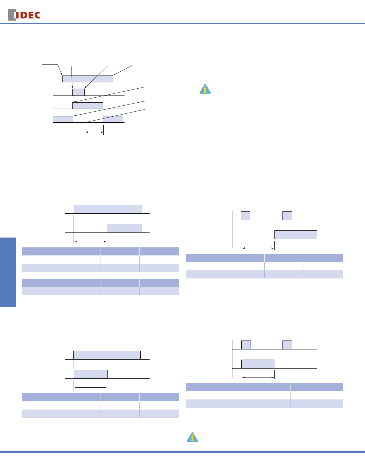
Guide to Reading Timing Function Diagrams
Timers
Timing Diagrams Overview
Power
Applied
Timer Power
Switches & Pilot LightsDisplay LightsRelays & SocketsTimersTerminal Blocks
Input Signal
NO Contact
NC Contact
Start Input
Terminals Shorted
Set Time
Start Input
Terminals Opened
Power
Removed
NO Contact Closes
NC Contact Opens
Timer Begins Counting
Timing Function Diagrams Overview
ON-Delay 1 (power start)
When voltage is applied to the coil, the relay contacts remain in the off state
and the set time begins. When the set time has elapsed, the relay contacts
transfer to the on state. The contacts remain in the on state until the timer is
reset. The timer is reset by removing the coil voltage. Applicable models: RTEP(B)1, GT3A-1, -2, -3, GT3D-1, -2, -3, -4, and GE1A.
Power
Output
T
Type No. GT3A-1, -2, -3 GT3D-1, -2, -3, -4 RTE-*1
Mode A 1-A A
See Page 805 813 798
Type No. GE1A GT5P GT5Y
See Page 844 813 853
Interval 1 (power start)
When voltage is applied to the coil, the relay contacts transfer immediately to
the on state and the set time begins. When the set time has elapsed, the relay
contacts transfer to the off state. The contacts remain in the off state until the
timer is reset. The timer is reset by removing the coil voltage. Applicable models:
RTE-P(B)1, GT3A-1, -2, -3, and GT3D-1, -2, -3, -4.
1. If power is disconnected during actual timing, most electronic timers reset to the
preset time, ready for the re-application of supply voltage
(except for GT3F “true OFF Delay”).
2. NO = Normally open.
3. NC = Normally closed.
ON-Delay 2 (signal start)
Voltage is applied to the coil at all times. When a start input is supplied, the
relay contacts remain in the off state and the set time begins. When the set
time has elapsed, the relay contacts transfer to the on state. The contacts
remain in the on state until the timer is reset. The timer is reset by applying a
reset input or by removing the coil voltage. Applicable models: GT3A-4, GT3D-4
and RTE-P(B) 2.
Start Input
Output
T
Type No. GT3A-4 GT3D-4 RTE-*2
Mode A 2-A A
See Page 805 813 798
Interval 2 (signal start)
Voltage is applied to the coil at all times. When a start signal is supplied, the
relay contacts transfer immediately to the on state and the set time begins.
When the set time has elapsed, the relay contacts transfer to the off state. The
contacts remain in the off state until the timer is reset. The timer is reset by applying a reset input or by removing the coil voltage. Applicable models: GT3A-5
and GT3D-4.
Start Input
Power
Output
T
Type No. GT3A-1, -2, -3 GT3D-1, -2, -3, -4 RTE-*1
Mode B 1-B B
See Page 805 813 798
Circuit Breakers
794
Output
T
Type No. GT3A-5 GT3D-4
Mode A 2-E
See Page 805 813
1. T = set time, T’ = shorter than set time, Ts = one shot output time
2. For more detailed timing diagrams, see specifi cations for individual timer models.
www.idec.com
Timers
Timing Diagrams Overview
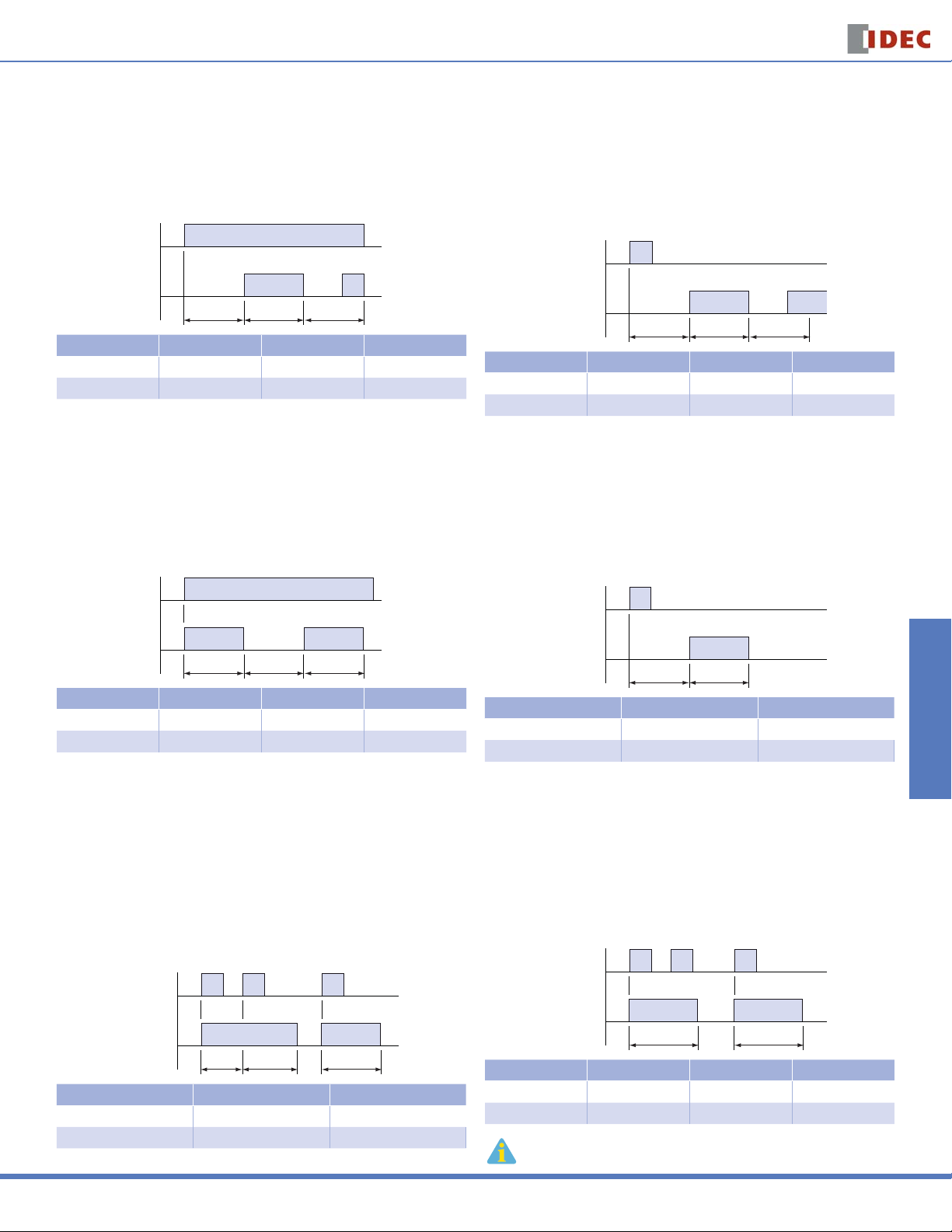
Cycle 1 (power start, OFF fi rst)
When voltage is applied to the coil, the contacts remain in the off state and the
set time begins. At the end of the set time, the contacts transfer to the on state
and remain in the on state until the set time elapses. The timer cycles between
the two states until power is removed from the coil. Removing the coil voltage
resets the timer. The set time for both the on state and the off state is the
same. Applicable models: GT3A-1, -2, -3, GT3D-1, -2, -3, -4 and RTE-P(B)1.
Power
Output
TTT
Type No. GT3A-1, -2, -3 GT3D-1, -2, -3, -4 RTE-*1
Mode C 1-C C
See Page 805 813 798
Cycle 3 (power start, ON fi rst)
When voltage is applied to the coil, the contacts immediately transfer to the on
state and the set time begins. At the end of the set time, the contacts transfer
to the off state and remain in the off state until the set time elapses. The timer
cycles between the two states until power is removed from the coil. Removing
the coil voltage resets the timer. The set time for both the off state and the
on state is the same. Applicable models: GT3A-1, -2, -3, GT3D-1, -2, -3, -4 and
RTE-P(B)1.
Cycle 2 (signal start, OFF fi rst)
Switches & Pilot Lights Display Lights Relays & Sockets Timers Terminal Blocks
Voltage is applied to the coil at all times. When a start signal is supplied, the
relay contacts remain in the off state and the set time begins. At the end of the
set time, the contacts transfer to the on state and remain in the on state until
the set time elapses. The timer cycles between the two states until the timer
is reset. The set time for both the on state and the off state are the same. The
timer is reset by application of a reset input or by removing coil voltage. Applicable models: GT3A-4, GT3D-4 and RTE-P(B) 2.
Start Input
Output
TTT
Type No. GT3A-4 GT3D-4 RTE-*2
Mode B 2-B B
See Page 805 813 798
One Shot Cycle (signal start)
Voltage is applied to the coil at all times. When a start signal is supplied, the contacts remain in the off state and the set time begins. At the end of the set time,
the contacts transfer to the on state and remain in the on state for the set time.
After the set time has elapsed, the contacts return to the off state. The contacts
remain in the off state until the timer is reset. The timer is reset by application of
a reset input or by removing coil voltage. Applicable models: GT3A-5 and GT3D-4.
Power
Output
TTT
Type No. GT3A-1, -2, -3 GT3D-1, -2, -3, -4 RTE-*1
Mode D 1-D D
See Page 805 813 798
One Shot 1 (signal start, retriggerable)
Voltage is applied to the coil at all times. When a start signal is supplied, the
contacts immediately transfer to the on state and the set time begins. If another
start signal is supplied (before set time has elapsed) the set time restarts,
as the contacts remain in the on state. Successive pulses at a frequency
greater than the set time will cause the contacts to remain in the “On state”
indefi nitely. When the set time has elapsed the contacts transfer back to the off
state. The contacts remain in the off state until the next start signal is supplied
(no reset is necessary). The timer can be reset by application of a reset input or
by removing coil voltage. Applicable models: GT3A-6 and GT3D-4.
Start Input
Output
TTT
Type No. GT3A-6 GT3D-4
Mode A 3-C
See Page 805 813
Start Input
Output
TT
Type No. GT3A-5 GT3D-4
Mode B 2-F
See Page 805 813
One Shot 2 (signal start)
Voltage is applied to the coil at all times. When a start signal is supplied, the
contacts immediately transfer to the on state and the set time begins. If another
start signal is supplied (before set time has elapsed), the set time will not be
affected. When the set time has elapsed, the contacts transfer back to the off
state. The contacts remain in the off state until the next start signal is supplied
(no reset is necessary). The timer can be reset by application of a reset input or
by removing coil voltage. Applicable models: GT3A-6, GT3D-4, and RTE-P(B)2.
Start Input
Output
TT
Type No. GT3A-6 GT3D-4 RTE-*2
Mode C 3-E F
See Page 805 813 798
1. T = set time, T’ = shorter than set time, Ts = one shot output time
2. For more detailed timing diagrams, see specifi cations for individual timer models.
Circuit Breakers
USA: 800-262-IDEC Canada: 888-317-IDEC
795

Timing Diagrams Overview
Timers
Signal ON/OFF-Delay 1
Voltage is supplied to the coil at all times. When a maintained start signal is
supplied, the contacts immediately transfer to the on state and the set time begins. When the set time has elapsed, the contacts transfer to the off state. The
contacts remain in the off state until the start signal is removed. The contacts
transfer back to the on state and remain in the on state for the set time. When
the set time has elapsed, the contacts transfer to the off state and remain in the
off state until the start signal is supplied again (no reset is necessary). The timer
Switches & Pilot LightsDisplay LightsRelays & SocketsTimersTerminal Blocks
is reset by application of a reset input or by removing coil voltage. Applicable
models: GT3A-4, GT3D-4 and RTE-R(B)2.
Start Input
Output
TT
Type No. GT3A-4 GT3D-4 RTE-*2
Mode C 2-C D
See Page 805 813 798
Signal ON/OFF-Delay 3
Voltage is supplied to the coil at all times. When a momentary start signal is
supplied, the contacts remain in the off state and the set time begins. When the
set time has elapsed, the contacts transfer to the on state. The contacts remain
in the on state until another momentary input is supplied. The contacts then
remain in the on state for the set time. When the set time has elapsed, the contacts transfer to the off state and remain in the off state until the start signal is
supplied again (no reset is necessary). The timer is reset by application of a reset
input or by removing coil voltage. Applicable models: GT3A-6 and GT3D-4.
Signal ON/OFF-Delay 2
Voltage is supplied to the coil at all times. When a maintained start signal is
supplied, the contacts remain in the off state and the set time begins. When
the set time has elapsed, the contacts transfer to the on state. The contacts
remain in the on state until the start signal is removed. Once the start signal
is removed, the contacts remain in the on state and the set time begins again.
Once the set time has elapsed, the contacts transfer back to the off state. The
timer is ready for the next start signal. The timer is reset by the application of a
reset signal or removal of power. Applicable models: GT3A-5 and GT3D-4.
Start Input
Output
TT
Type No. GT3A-5 GT3D-4
Mode C 3-A
See Page 805 813
Signal OFF-Delay 1
Voltage is applied to the coil at all times. When a start signal is supplied, the
contacts immediately transfer to the on state. The set time begins when the
start signal is removed. When the set time has elapsed, the contacts transfer
to the off state. The contacts remain in the off state until the next start signal is
supplied (no reset is necessary). The timer can be reset by application of a reset
input or by removing coil voltage. Applicable models: RTE-P(B)2, GT3A-4, and
GT3D-4.
Start Input
Start Input
Output
TT
Type No. GT3A-6 GT3D-4
Mode D 3-F
See Page 805 813
One Shot ON-Delay (signal start)
When voltage is applied to the coil, the preset time is initiated and the contacts
remain in the off state for the preset time. Following the preset time, the
contacts transfer to the on state, and remain in the on state until the start input
is supplied. Following the start input, the contacts transfer to the off state for
the preset time. After the preset time has elapsed, the contacts transfer back to
the on state and remain there until either the next start input is supplied or the
timer is reset. The timer can be reset by either a reset input or removal of the
coil voltage. Applicable models: GT3A-6 and GT3D-4.
Start Input
Output
T
Type No. GT3A-6 GT3D-4
Mode B 3-D
Circuit Breakers
See Page 805 813
Output
T
Type No. GT3A-4 GT3D-4 RTE-*2
Mode D 2-D E
See Page 805 813 798
Signal OFF-Delay 2
Voltage is applied to the coil at all times. When a maintained start signal is supplied, the contacts remain in the off state. When the “start signal is removed”,
the contacts transfer to the “On state” and the set time begins. When the set
time has elapsed, the contacts transfer back to the off state. They remain in
the off state until the next start signal is supplied (no reset is necessary. The
timer can be reset by application of a reset input or by removing coil voltage.
Applicable models: GT3A-5 and GT3D-4.
Start Input
Output
T
Type No. GT3A-5 GT3D-4
Mode D 3-B
See Page 805 813
1. T = set time, T’ = shorter than set time, Ts = one shot output time
2. For more detailed timing diagrams, see specifi cations for individual timer models.
796
www.idec.com

Timers
Timing Diagrams Overview
ON-Delay One-Shot Output 1 (signal start)
Voltage is applied to the coil at all times. When a momentary start signal is supplied, the contacts remain in the off state and the preset time begins. Following
the preset time, the contacts transfer to the on state and remain in the on state
for the one-shot preset time. Following the one-shot preset time, the contacts
transfer back to the off state and remain there until the timer is reset. The timer
can be reset by applying either a reset input or removal of the coil voltage. Applicable model: GT3D-8.
Start Input
Output
TsT
Type No. GT3D-8
Mode 1
See Page 813
ON-Delay One-Shot Output 2 (signal start)
Voltage is applied to the coil at all times. When a maintained start signal is supplied, the contacts remain in the off state and the preset time begins. Following
the preset time (start input is still present), the contacts transfer to the on state
and remain in the on state for the one-shot preset time. When the one-shot
preset time has elapsed, contacts transfer back to the off state and remain
there until timer is reset. The timer can be reset by a reset input, removal of the
coil voltage or removal of start input. Applicable model: GT3D-8.
Cycle One-Shot Output (signal start)
Switches & Pilot Lights Display Lights Relays & Sockets Timers Terminal Blocks
Voltage is applied to the coil at all times. When a momentary start signal is supplied, the contacts remain in the off state and the preset time begins. Following
the preset time, the contacts transfer to the on state. The contacts remain in
the on state for the one-shot preset time. After the one-shot preset time has
elapsed, the contacts transfer back to the off state. The contacts remain in the
off state for the preset time minus the one-shot preset time. The timer cycles
between on and off states until the timer is reset by a reset input or removal of
the coil voltage. Applicable model: GT3D-8.
Start Input
Output
TTs TsTTs
T
Type No. GT3D-8
Mode 2
See Page 813
True Power-OFF Delay
When voltage is applied, output comes on immediately; when voltage is
removed from the coil, the timer begins timing (internal capacitors power the
timing circuit). When time has expired, contacts transfer back to the OFF state. If
power is reapplied before the elapsed time has expired, the timing function will
reset back to the starting point. Applicable models: GT3F-1, 2.
Start Input
Output
TsT
Type No. GT3D-8
Mode 3
See Page 813
Sequential Start (power start)
When voltage is applied to the coil, both contacts remain in the OFF state
and the set time, T1, begins. When T1 has elapsed, output 1 comes on and T2
begins. When T2 has elapsed, output 2 comes on. Both outputs remain on until
power is removed from the coil. Applicable model: GT3W-A.
Start Input
Output
T1 T2
Type No. GT3W-A
Mode A
See Page 834
Start Input
Output
T
Type No. GT3F-1, 2
Mode Power OFF-Delay
See Page 826
Recycler Outputs (power start)
When voltage is applied to the coil, both contacts remain in the off state and
time T1 begins. When T1 has elapsed, both contacts transfer to the ON state
and T2 begins. When T2 has elapsed, both contacts transfer back to the OFF
state and T1 begins again. The cycle continues until power is removed, at which
time both contacts transfer back to the OFF state. Applicable model: GT3W-A.
Start Input
Output
T1 T2 T1 T2
Type No. GT3W-A
Mode D
See Page 834
1. T = set time, T’ = shorter than set time, Ts = one shot output time
2. For more detailed timing diagrams, see specifi cations for individual timer models.
Circuit Breakers
USA: 800-262-IDEC Canada: 888-317-IDEC
797
 Loading...