

Page 1
DECLARATION OF CONFORMITY
We DATASENSOR S.p.A. declare under our sole responsibility that these products are conform to the 2004/108/CE,
2006/95/CE Directives and successive amendments
WARRANTY
DATASENSOR S.p.A. warrants its products to be free from defects.
DATASENSOR S.p.A. will repair or replace, free of charge, any product found to be defective during the warranty period of
36 months from the manufacturing date.
This warranty does not cover damage or liability deriving from the improper application of DATASENSOR products.
DATASENSOR S.p.A. Via Lavino 265
40050 Monte S. Pietro - Bologna - Italy
Tel: +39 051 6765611 Fax: +39 051 6759324
http://www.datasensor.com e-mail: info@datasensor.com
DATASENSOR S.p.A. cares for the environment: 100% recycled paper.
DATASENSOR S.p.A. reserves the right to make modifications and improvements without prior notification.
830000201 Rev.A
Copyright © 2008-2009 Datasensor
SERIES
SAFETY INFORMATION
The following points must be observed for a correct and safe use of the
The stopping system of the machine must be electrically controlled.
This control system must be able to stop the dangerous movement of the machine within the total
machine stopping time T as per paragraph 1.3.3 of the manual included in the CD supplied and duri ng all
working cycle phases.
Mounting and connection of the safety light curtain must be carried out only by qualified personnel,
according to the indications included in the special sections (refer to sections 2; 3; 4; 5) and in respect to
the applicable Standards.
The safety light curtain must be securely installed so that access to the dangerous zone is not possible
without interrupting the beams.
The personnel o perating in the dangerous area must be well-trained and must have adequate kno wledge
of all the operating procedures of the safety light curtain.
The TEST and RESET/RESTART buttons must be located outside the protected area as the operator
must check the protected area during all Test and Restart operations.
Please carefully read the instructions for the correct functioning before powering the light curtain.
safety light curtains of the SG4-B series:
Precautions to be observed for the choice and installation of the device
Make sure that the protection level assured by the SG4 device
(Type 4) is compatible with the real danger level of the machine to be
The outputs (OSSD) of the ESPE must be used as machine stopping devices and not as command
devices. The machine must have its own START command.
The dimension of the smallest object to be detected must be larger than the resolution level of the device.
The ESPE must be installed in a room complying with the technical characteristics indicated in section 10
“Technical data” of the manual included in the CD supplied.
Do not place the device near intense and/or flashing light sources and, in particular, close to receiving unit
front surface.
controlled, according to EN 954-1 and EN 13849-1.
Safety light curtains with infrared beams
QUICK GUIDE
1
Page 2
The presence of intense electromagnetic disturbances could jeopardise device operation. This condition
has to carefully evaluated with the support of the DATASENSOR Technical service.
The operating distance of the device can be reduced in presence of smog, fog or airborne dust.
A sudden change in environment temperature, with very low minimum peaks, can generate a small
condensation layer on the lenses and so jeopardise functioning.
Reflecting surfaces near the safety light curtain light beam (above, under or lateral) can cause passive
reflections that can jeopardise functioning.
The safety device must be installed at a distance which is major or equal to the minimum safety
distance S to ensure that the operator can not reach the dangerous area until t he moving dangerous
object has been blocked by the ESPE.
The failure to respect the safety distance reduces
or cancels ESPE the protection function.
For more detailed information about calculation of safety distance,
please refer to the complete manual contained in the CD supplied.
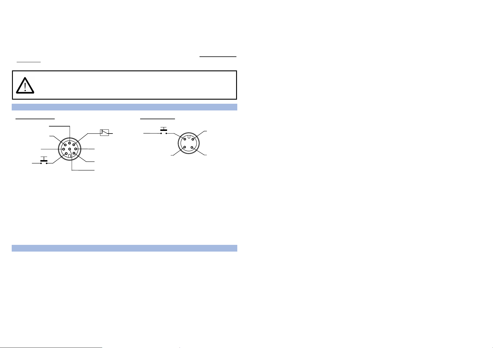
CONNECTIONS
RECEIVER (RX) EMITTER (TX)
TEST
N.O.
0 V
2
3 4
1
+24 Vdc
NOT USED
OSSD1
OSSD2
0 V
N.O.
+24 Vdc
RESET / RESTART
+24 Vdc
4
EDM
N.C. external contact
3
2
5
6
7
1
8
+24 Vdc
EDM
SELECTION
+24 Vdc
MAN/AUTO
SELECTION
1 = white = RESET / RESTART(*)
2 = brown = +24Vdc
3 = green = EDM SELECTION
4 = yellow = EDM
5 = grey = OSSD 1
6 = pink = OSSD 2
7 = blue = 0V
8 = red = MANUAL/AUTOMATIC RESTART
(*) Automatic RESTART RESET function
Manual RESTART RESET/RESTART function
1 = brown = +24 Vdc
2 = white = TEST
3 = blue = 0V
4 = black =
NOT USED
ALIGNMENT PROCEDURE
The alignment between the emitting and the receiving units is necessary to obtain the corr ect functioning of
the light curtain.
A good alignment prevents output instability caused by dust or vibrations.
The alignment is perfect if the optical axes of the first and the last emitting unit beams coincide with the
optical axes of the corresponding elements of the receiving unit.
The beam used to synchronise the two units is the first after the connector. SYNC is the optics connected
with this beam and LAST is the optics connected to the last beam after the SYNC unit.
2
Page 3

For emitter:
sy
Function Status Meaning LED DIGIT
Normal operation
Function Type Check and repair LED DIGIT
Error status
TEST
(green ON)
Emission
(green ON yellow
ON)
Internal error
(green ON)
Optical error
(green ON)
No power supply
(LEDs OFF)
Light curtain being tested . OSSD status on
the receiver must be OFF
Light curtain in normal operating condition
Switch OFF and switch ON the power
supply circuit. If the failure continues
contact DATASENSOR
Switch OFF and switch ON the power
supply circuit. If the failure continues
contact DATASENSOR
Check connections and input voltage
correct value. If the failure continues
contact DATASENSOR
6
Last optics (LAST)
First optics (SYNC) =
nchronisation optics
NORMAL
OP.
SAFE
Receiver
LAST
SYNC
Emitter
NORMAL
OP.
ON
Signals are clearly identified through symbols allowing immediate reading, independent of bars directions.
A short description of the signalling LEDs is necessary to avoid misunderstandings.
Two yellow LEDs ( LAST, SYNC) on SG4-B receiver, facilitate the alignment procedure.
Correct alignment procedure
The light curtain alignment can be effected only after having completed the mechanical installation and the
electrical connections. The following procedure has to be followed:
: SG4-B is equipped with a system which informs the user on the alignment obtained.
NOTE
The alignment function can be activated w hen powering the device, by keeping the normall y open
RESET/RESTART contact closed for at least 0.5 seconds.
LED
SAFE
(BREAK)
Display
LED
NORMAL
OP.
OFF ON
ON OFF OFF OFF
ON OFF OFF OFF
ON OFF OFF OFF
ON OFF OFF OFF
LED
yellow
SYNC
ON
OFF
OFF OFF
LED
yellow
LAST
ON
Condition
Sync NOK
Last NOK
Sync OK
Last NOK
Sync OK
Last OK
Middle optics NOK
Each beam is over the min.
operating threshold and the
number of beam over the
threshold is included between
Each beam is over the min.
operating threshold and the
number of beam over the
threshold is included between
25 and 50%
Each beam is over the min.
operating threshold and the
number of beam over the
threshold is included between
50 and 75%
Each beam is over the min.
operating threshold and the
number of beam over the
threshold is included between
75 and 100%
0 and 25%
Alignment
Status
NO align.
MINIMUM
align.
MAXIMUM
align.
3
Page 4

A Keep the receiver in a steady position and set the emitter until the yellow LED ( SYNC) is OFF.
This condition shows the effective alignment of the first beam (synchronisation beam).
B Rotate the emitter, pivoting on the lower optics axis, until the yellow LED (
LAST) is OFF.
NOTE: Ensure that the green LED (
NORMAL OP.) is steady ON.
C Delimit the area in which the green LED ( ) is steady through some micro adjustments - for the first
and then for the second unit - so to have the maximum alignment (4) and then place both units in the
centre of this area.
D Fix the two units firmly using brackets.
Verify that the green LED (
the red LED turns ON if even one single beam is interrupted SAFE(BREAK)
) on the RX unit is ON and beams are not interrupted, then verify that
, condition where an
object has been detected).
This verification shall be made with the special cylindrical “Test Piece” having a size suitable to the
resolution of the device used (refer to paragraph 2.2.6 “Controls after first installation”).
E Switch OFF and ON the device in standard operating mode.
The alignment level is monitored also during device normal operation mode via display (see paragraph
7.2 on the manual inside of the attached CD-ROM).
Once the curtain has been aligned and correctly fastened, the display signal is useful both to check the
alignment and show a change in the environmental conditions (occurrence of dust, light disturbance and
so on) via signal level monitoring.
DIAGNOSTICS FUNCTION
The operator can visualise the operating condition of the light curtains thanks to a one-digit display
positioned on both the RX and TX unit. SG4-B also has four LEDs on the RX unit and two LEDs on the TX
unit.
The figure below shows all signalling LEDs modes: OFF, ON and BLINKING.
LED OFF
LED ON
4
LED BLINKING
The operator can evaluate the main causes of the system stopping or failure using the 7-segment display
and LEDs used to visualise the functions. For the receiver:
Function Status Meaning LED DIGIT
Alignment See section 5
TEST
(red ON)
Emission
(OSSD ON)
(green ON)
Interruption
(OSSD OFF)
(red ON)
Normal operation
Function Type Check and repair LED DIGIT
Error status
Interlock
Beams free
(red ON
yellow ON)
Interlock
Beams interrupted
(red ON
yellow ON)
Signal level
EDM enabled EDM function is selected
OSSD error
(red ON)
Internal error
(red ON)
Optical error
(red ON)
EDM error
(red ON)
Restart selection
error (red ON)
No power supply
(LEDs OFF)
Light curtain being tested . OSSD status
shall be OFF
Light curtain working in normal operating
conditions
Light curtain working in safety block
conditions.
Light curtain in interlock, waiting for
restart. OSSD status must be OFF
Light curtain in interlock. OSSD status
must be OFF
Minimum (1 bar)
Medium (2 bar)
Maximum (3 bar)
Check OSSD connections. Make sure that
they are not in contact with one another or
with the supply cables, then Reset. If the
failure continues contact DATASENSOR
Switch OFF and switch ON the power
supply circuit. If the failure continues
contact DATASENSOR
Reset. If the failure continues contact
DATASENSOR
Check EDM connections and lines. If the
failure continues contact DATASENSOR
Check the man/auto restart connection. If
the failure continues contact
DATASENSOR
Check connections and input voltage
value. If the failure continues contact
DATASENSOR
5
 Loading...