

FUNCTION
-
CANCEL
ENTER
+
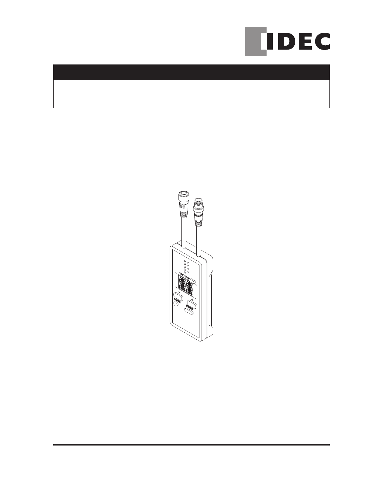
INSTRUCTION MANUAL
Handy Controller Exclusive for SE4D Series
SE9Z-HC
B-1430(0)
MJE-SE9ZHC No.0027-96V

1
(MEMO)

2
Thank you for purchasing IDEC’s Handy Controller SE9Z-HC exclusive for SE4D series.
Please read both the instruction manual of this manual and SE4D series carefully and thoroughly for
the correct and optimum use of this device.
Kindly keep this manual in a convenient place for quick reference.
This manual has been written for the following personnel who have undergone suitable training and
have knowledge of light curtains, as well as, safety systems and standards (ANSI, etc.).
● who are responsible for the introduction of this device
● who design a system using this device
● who install and connect this device
● who manage and operate a plant using this device
1) All the contents of this instruction manual are the copyright of the publishers, and may not be
reproduced (even extracts) in any form by any electronic or mechanical means (including
photocopying, recording, or information storage and retrieval) without permission in writing
from the publisher.
2) The contents of this instruction manual may be changed without prior notice for further
improvement of the device.
3) A part of / all of this instruction manual or the software may not be copied without permission
from the publisher.
4) Though we have carefully drawn up the contents of this instruction manual, if there are any
aspects that are not clear, or any error that you may notice, please contact our local IDEC
ofce or the nearest distributor.
5) We shall not be responsible for any consequences of use regardless of the descriptions
above.
NOTICE

3
Contents
CHAPTER 1 INTRODUCTION ..............................................................................4
1-1 Attention Marks ..................................................................................................... 4
1-2 Safety Precautions ................................................................................................4
CHAPTER 2 GENERAL OUTLINE .......................................................................6
2-1 Features ................................................................................................................6
2-2 Part Descriptions ..................................................................................................6
2-3 Connecting / Setting Procedures .......................................................................... 7
CHAPTER 3 FUNCTIONS ....................................................................................8
3-1 Functional Descriptions ........................................................................................8
3-1-1 Fixed Blanking Function.....................................................................................8
3-1-2 Floating Blanking Function.................................................................................9
3-1-3 Auxiliary Output Switching Function...................................................................10
3-1-4 Emission Intensity Control Function...................................................................11
3-1-5 Copy Function ....................................................................................................11
3-1-6 Muting Setting Changing Function .....................................................................11
3-1-7 Interlock Setting Changing Function ..................................................................12
3-1-8 External Device Monitor Setting Changing Function .........................................12
3-1-9 Protective Function ............................................................................................13
3-1-10 Initialization Function .......................................................................................13
3-1-11 Setting Contents Monitoring Function ..............................................................13
3-1-12 Override Setting Changing Function ................................................................13
3-2 Function Setting (Operation Procedure) ............................................................... 14
3-2-1 Fixed Blanking Function.....................................................................................17
3-2-2 Floating Blanking Function.................................................................................18
3-2-3 Auxiliary Output Switching Function...................................................................19
3-2-4 Emission Intensity Control Function...................................................................20
3-2-5 Copy Function ....................................................................................................21
3-2-6 Muting Setting Changing Function .....................................................................22
3-2-7 Interlock Setting Changing Function ..................................................................24
3-2-8 External Device Monitor Setting Changing Function .........................................25
3-2-9 Protective Function ............................................................................................26
3-2-10 Initialization Function .......................................................................................27
3-2-11 Setting Contents Monitoring Function ..............................................................28
3-2-12 Override Setting Changing Function ................................................................29
CHAPTER 4 TROUBLESHOOTING .....................................................................30
CHAPTER 5 SPECIFICATIONS / DIMENSIONS ..................................................31
5-1 Specications ........................................................................................................31
5-2 Dimensions ........................................................................................................... 31

4
CHAPTER 1 INTRODUCTION
1-1 Attention Marks
This instruction manual employs the following attention marks , depending on the
degree of the danger to call operator’s attention to each particular action. Read the following
explanation of these marks thoroughly and observe these notices without fail.
Besides, the attention mark is prepared for the helpful information, detail instruction related to each
part, and reference item or page.
If you ignore the advice with this mark, death or serious injury could result.
If you ignore the advice with this mark, injury or material damage could result.
Remarks
The supplementary content is described with this mark.
REFERENCE
The related content is described with this mark.
1-2 Safety Precautions
■ Use this device as per its specifications. Do not modify this device since its functions and
capabilities may not be maintained and it may malfunction.
■ This device has been developed / produced for industrial use only.
■ Before using this device, check whether the device performs properly with the functions and
capabilities as per the design specications.
■ In case of disposal, dispose this device as industrial waste.
♦ User in charge
● The user in charge has responsible to indicate the person to take the training required for the
safety system, using method, installation, operation, and maintenance.
● This device is used and managed by the specialist, never use this device by other operator.
♦ Specialist
● A person who is appropriately educated, has widespread knowledge and experience, and
can solve various problems which may arise during work.
♦ Operator
● The operator should read this instruction manual thoroughly, understand its contents, and perform
operations following the procedures described in this manual, for the correct operation of this device.
● In case this device does not perform properly, the operator should report this to the person in
charge and stop the machine operation immediately. The machine must not be operated until
correct performance of this device has been conrmed.

5
♦ Fixed blanking function, oating blanking function
● With the xed blanking function, this device prevents the person or object from entering into
the dangerous parts of the machine through the invalid sensing area. However, even though
this device can prevent the interference of the person or object into the invalid sensing area
with the xed blanking function, there might exist the more space between the SE4D series
and already-existence object. Therefore, set the protecting structure so as not to exist any
space in the dangerous sensing area. Detecting human body in the sensing area could result
in death or serious injury.
● With the floating blanking function, this device changes the size of the minimum sensing
object of the S E 4D series that is pre-set the function. When setting or changing the
function, calculate and measure the safety distance again, and check that the device has the
wider space than the safety distance between the dangerous parts of the machine and the
sensing area of the SE 4D serie s.
If the sufcient distance is not maintained, the machine will
not stop before its dangerous parts are reached, which can result in death or serious injury.
● Set and change the function of the device following the relative laws, regulation, and
standard without fail.
♦ Muting setting changing function
● The muting setting changing function temporarily invalidates safety function of the connected
devices. Conrm all of the applied laws and standards, and install or operate this device and
peripheral devices correctly. Failure to do so, the operator may suffer a serious injury.
♦ Environment
● Do not use a mobile phone or a radio phone near this device.
● Do not use this device in the following environments.
1) Areas with high humidity where condensation is likely to occur
2) Areas exposed to corrosive or explosive gases
3) Areas exposed to vibration or shock of levels higher than that specied
4) Areas exposed to contact with water
5) Areas exposed to too much steam or dust
♦ Wiring
● Be sure to carry out the wiring in the power supply OFF condition.
● All electrical wiring should conform to the regional electrical regulations and laws. The wiring
should be done by engineer(s) having the special electrical knowledge.
● Do not run the wires together with high-voltage lines or power lines or put them in the same
raceway. This can cause malfunction due to induction.
♦ Maintenance
● Clean this device with a clean cloth. Do not use any volatile chemicals.
♦ Other
● Never reassemble or remodel this device.
INTRODUCTION
6
CHAPTER 2 GENERAL OUTLINE
This chapter gives the system construction, part description, etc. of this device.
2-1 Features
Thi s dev ice is t h e han dy c ontr oller for setti ng e ach funct ion of the ligh t curt ain SE4D
se ries.
Beside s , th i s d e vice performs th e ch e cking and copying th e se t ting contents of th e
fu nction, and prot ection o f writin g.
<Functions>
● Fixed blanking function
● Floating blanking function
● Auxiliary output switching function
● Emission intensity control function
● Copy function
● Muting setting changing function
● Interlock setting changing function
● External device monitor setting changing function
● Protective function
● Initialization function
● Setting contents monitoring function
● Override setting changing function
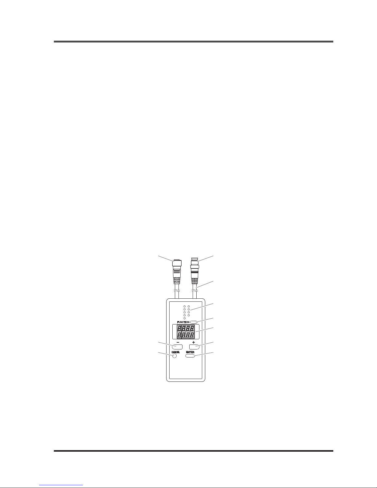
2-2 Part Descriptions
FUNCTION
-
CANCEL
ENTER
+
Male connector
Cable (0.5m)
FUNCTION indicator × 9
(Green)
FUNCTION switch
Digital display (Red)
+ switch
ENTER switchCANCEL switch
- switch
Female connector
7
Connecting / Setting Procedures
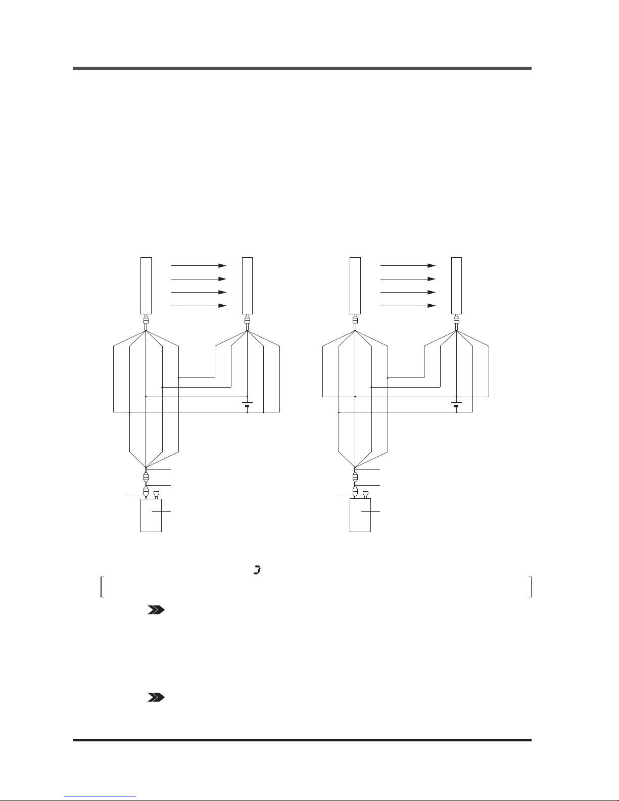
2-3 Connecting / Setting Procedures
This section describes the connecting / setting procedures for both this device and SE4D series.
1. Set the SE4D series, and check that the
SE4D series works properly. For mounting
method o f SE 4 D se r i e s , re fer t o th e
Instruction Manual.
2. Tur n OFF the powe r and conn ect this
device to the SE4D series. Use the handy
controller connection cable (SE9Z-WNC1)
for the connection. The handy controller
connection cable (SE9Z-WNC1) can be
connec ted by c onn ecti ng the include d
SE9Z-CCJ02-HC1 to the device’s female
connector.
3. Turn ON the power, and set the function with this device.
After the power of this device is ON, approx. 30 sec. will be taken for data transmission with SE4D
series. While data transmission, “
” lights up in revolving.
The control output (OSSD 1 / 2) of SE4D series is set to “OFF” while this device has been
connected.
REFERENCE Refer to “3-1 Functional Descriptions” for the details of the functions, and refer to “3-2
Function Setting (Operation Procedure)” for the setting procedures of the functions
respectively.
4. Turn OFF the power, then remove this device.
5. Check that the SE4D series works as set at the procedure 3.
Then, inspect the SE4D series.
REFERENCE Refer to “Chapter 4 Maintenance” of the SE4D series instruction manual for the details of
the inspection of the SE4D series.
<For PNP output> <For NPN output>
24V±10%
+
-
Emitter
Receiver
(Shield)
(Blue)
(Brown)
(Orange)
(Orange
/ Black)
(Blue)
(Brown)
(Orange)
(Orange
/ Black)
(Shield)
(Blue)
(Brown)
(Orange)
(Orange / Black)
24V±10%
+
-
Emitter
Receiver
(Shield)
(Blue)
(Brown)
(Orange)
(Orange
/ Black)
(Blue)
(Brown)
(Orange)
(Orange
/ Black)
(Shield)
(Blue)
(Brown)
(Orange)
(Orange / Black)
Handy controller connection
cable (SE9Z-WNC1)
This device
SE9Z-CCJ02-HC1
Female
connector
Handy controller connection
cable (SE9Z-WNC1)
This device
SE9Z-CCJ02-HC1
Female
connector
8
CHAPTER 3 FUNCTIONS
If conguration of the system is changed (replace the SE4D series etc.), set the function
again.
3-1-1 Fixed Blanking Function
This is a function that the control output (OSSD 1 / 2) of SE4D series is not turned OFF, even if the
specied beam channel(s) is blocked OFF.
This is useful when an obstacle always blocks OFF the specic beam channel(s).
There are “Clear,” “Auto” and “Manual” for the setting method.
● Clear setting : The xed blanking function is to be invalid (factory setting).
● Auto setting : The currently blocked OFF beam channels are set as “effective beam channels”
in the xed blanking function. Be sure to set this function in the state where the
emitter emits light. Furthermore, this function cannot be set in the state where all
beam channels receive lights / are blocked.
● Manual setting : Each beam channel can be set to “effective / ineffective” in the fixed blanking
function respectively.
3-1 Functional Descriptions
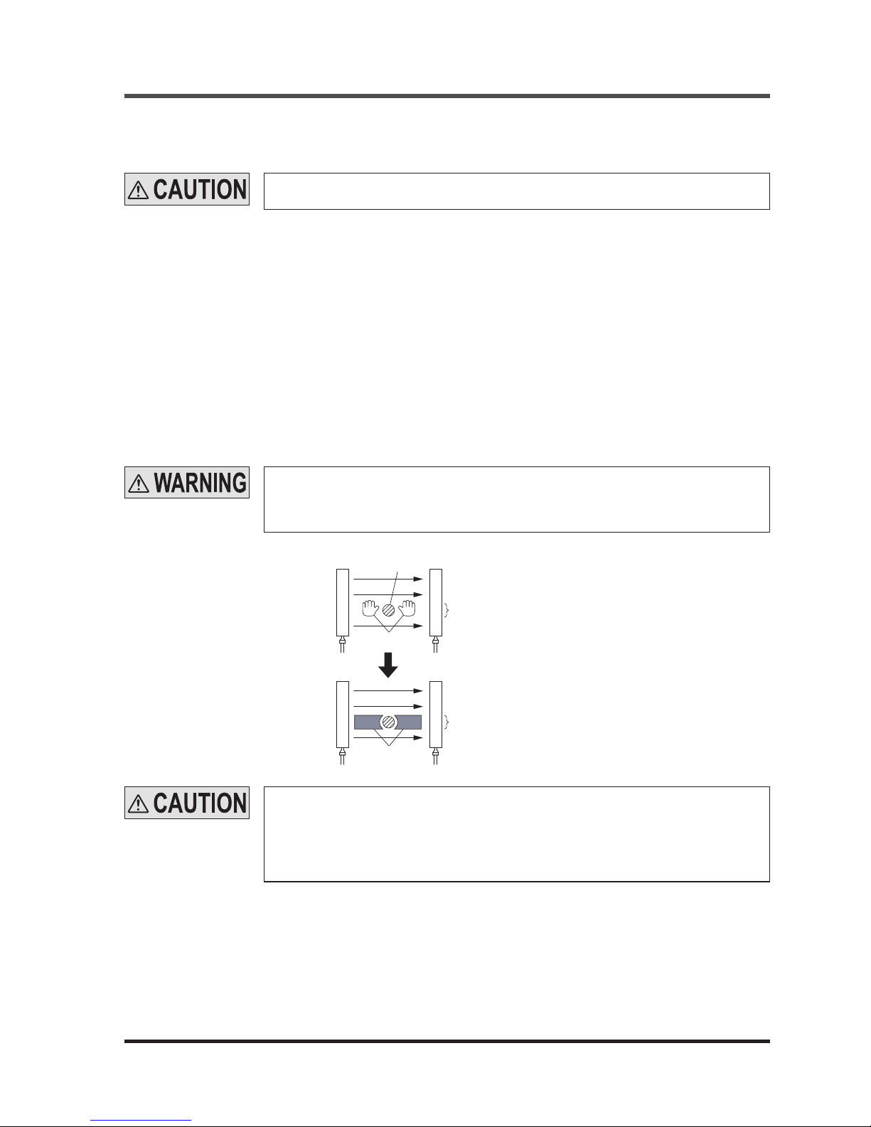
When the xed blanking function is used, the control output (OSSD 1 / 2) of SE4D series
is not turned OFF even if the particular beam channels are blocked.
By using a protection structure etc., make the dangerous parts of the machine inaccessible
to personnel through the sensing area of the particular beam channels.
<Before measures>
<After measures>
Obstacle
Dangerous area
Protection structure
Beam channels the xed blanking
function has been set to ON
Beam channels the xed blanking
function has been set to ON
Emitter
Receiver
Emitter
Receiver
When the effective beam channel(s) in the xed blanking function receive(s) the beam(s)
from the emitter, the control output (OSSD 1 / 2) of the SE4D series is xed to “OFF.” In
this case, check the mounting condition and turn the power ON again.
(Even if the power is turned ON again, the xed blanking function still stays effective.)
When the xed blanking function is used, the received light intensity indicator of SE4D
series is turned OFF regardless of the received light intensity.

9
Functional Descriptions
3-1-2 Floating Blanking Function
This function is set in each SE4D series.
If the number of the blocked beam channels is less than the set number of the beam channels, the
control output (OSSD 1 / 2) of SE4D series is not turned “OFF.”
This function is useful when an obstacle moves within the sensing area.
The factory setting of this function is “ineffective.”
The following items can be set.
Set number of beam channels
● Selectable among 0 (the oating blanking function is ineffective), 1, 2 or 3.
Ineffective setting of both end beam channel
● “Effective / ineffective” of the oating blanking function for the both end beam channels can be
selected.
• SET (Effective) : The floating blanking function becomes ineffective for the both end beam
channels. In case either end of the beam channel is blocked, the control
output (OSSD 1 / 2) of SE4D series is turned “OFF” regardless of the set
number of the beam channels.
• CLR (Ineffective) : The floating blanking function becomes effective for all beam channels
including both end beam channels.
Non-serial beam channel setting
• SET (Effective) : Even if the beam channels are blocked discontinuously in the set beam
channels, the control output (OSSD 1 / 2) of SE4D series is turned “ON.”
(Discontinuous mode)
• CLR (Ineffective) : When the beam channels are blocked discontinuously even in the set beam
channels, the control output (OSSD 1 / 2) of SE4D series is turned “OFF.”
(Continuous mode)
[For use in Europe (EU) (as EN 999)] (Also applicable to ISO 13855)
(For intrusion direction perpendicular to the sensing area)
<In case that the minimum sensing object is ø40mm or less>
● Equation S = K × T + C
S : Safety distance (mm)
Minimum required distance between the sensing area surface and the dangerous parts of
the machine.
K : Intrusion velocity of operator’s body or object (mm/sec.)
Taken as 2,000 (mm/sec.) for calculation
T : Response time of total equipment (sec.)
T = T
m
+ T
SE4D
Tm: Maximum halting time of machine (sec.)
T
SE4D
: Response time of SE4D series (sec.)
C : Additional distance calculated from the size of the minimum sensing object of the SE4D
series (mm)
However, the value of C cannot be under 0.
C = 8 × (d - 14)
d: Diameter of the minimum sensing object (mm)
● When using the floating blanking function, the size of the minimum sensing object
becomes larger, and the safety distance is longer as well. For the calculation of the
safety distance, refer to the instruction manual enclosed with SE4D series.
● Before designing the system, refer to the relevant laws and standards of the region
where SE4D series is to be used and then install SE4D series.
● The minimum sensing object differs depending on the set number of the beam channels.
10
Functional Descriptions
<Minimum sensing object>
Floating blanking function
Ineffective
Effective
1 beam channel 2 beam channels 3 beam channels
SE4D-H□ ø25mm ø45mm ø65mm ø85mm
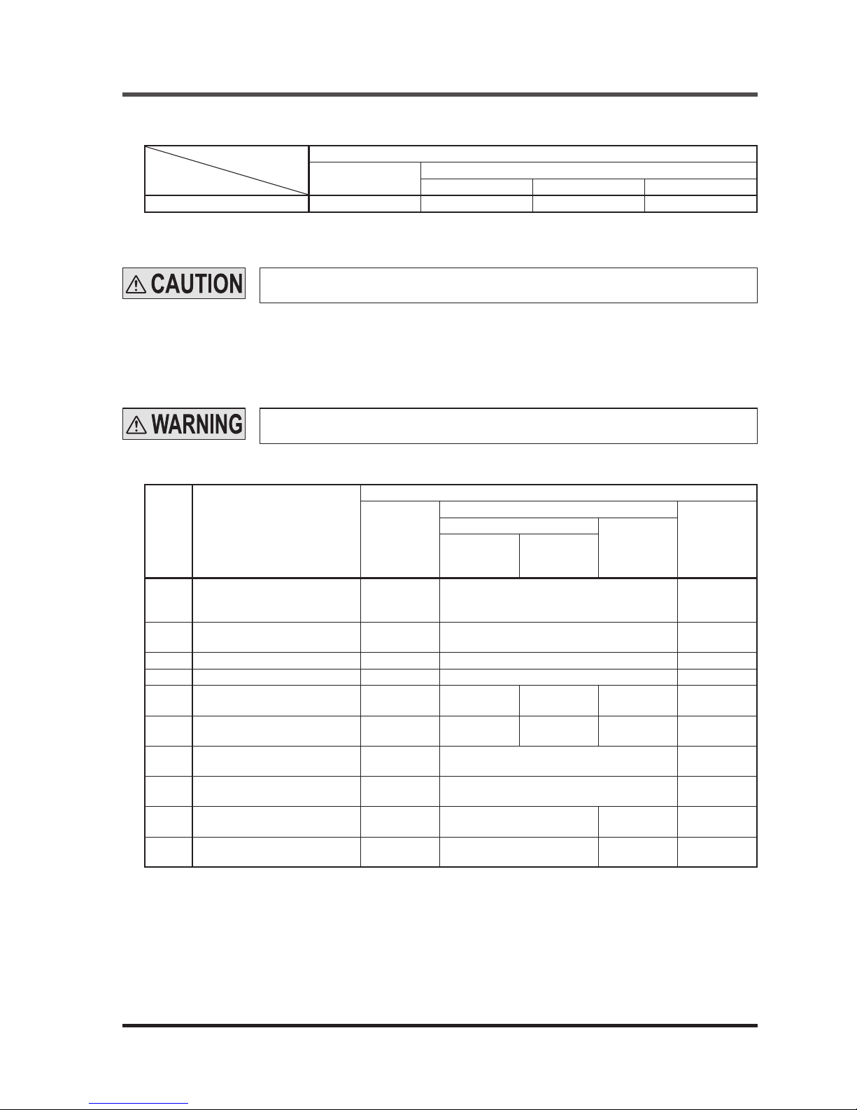
3-1-3 Auxiliary Output Switching Function
This function changes the operation state of the auxiliary output. It is useful when desired to make an
indicator to operate or inform the operation state of the SE4D series to PLC.
The following settings are selectable.
Setting
mode
Auxiliary output setting
Operation of the auxiliary output corresponding to SE4D series state
Emission
halt
State of sensing area when emitting
Lockout
Unshielded
Shielded
Unstable
light-receiving
condition
Others
0
Negative logic of the control
output (OSSD 1 / 2)
(factory setting)
ON
OFF when OSSD is ON
ON when OSSD is OFF
ON
1
Positive logic of the control
output (OSSD 1 / 2)
OFF
ON when OSSD is ON
OFF when OSSD is OFF
OFF
2 ON when emitting OFF ON OFF
3 OFF when emitting ON OFF ON
4
OFF under unstable light
receiving condition (Note 1)
(Note 3) OFF ON (Note 3) (Note 3)
5
ON under unstable light
receiving condition (Note 1)
(Note 3) ON OFF (Note 3) (Note 3)
6 ON during muting OFF
ON during muting
Others: OFF
OFF
7 OFF during muting ON
OFF during muting
Others: ON
ON
8
ON in light receiving condition
(Note 2)
OFF ON OFF OFF
9
OFF in light receiving condition
(Note 2)
ON OFF ON ON
Notes: 1) When the xed blanking function, the oating blanking function or the muting function is used, the setting of ON / OFF
under unstable light-receiving condition does not work.
2) By the setting of ON / OFF in light receiving condition, light-receiving / light interrupted condition is output regardless of
the xed blanking function, the oating blanking function or the muting function.
<e.g.>
When the fixed blanking function is used, if an obstacle exists in the set area and other area is in light receiving
condition, the control output (OSSD 1 / 2) is in ON sate, however, the auxiliary output becomes OFF since the SE4D
series has been detecting the obstacle.
3) The state of the auxiliary output remains the same even if the SE4D series state changes.
If the oating blanking function is used, the incident light intensity indicator is turned OFF
when an obstacle exists in the sensing range regardless of the incident light intensity.
Do not use the auxiliary output for the purpose of stopping the machine in which the SE4D
series is installed. Failure to do so could result in death or serious injury.
 Loading...