

Page 1
B-1430(0)
INSTRUCTION MANUAL
Handy Controller Exclusive for SE4D Series
SE9Z-HC
-
CANCEL
FUNCTION
+
ENTER
MJE-SE9ZHC No.0027-96V
Page 2

(MEMO)
1
Page 3

Thank you for purchasing IDEC’s Handy Controller SE9Z-HC exclusive for SE4D series.
Please read both the instruction manual of this manual and SE4D series carefully and thoroughly for
the correct and optimum use of this device.
Kindly keep this manual in a convenient place for quick reference.
This manual has been written for the following personnel who have undergone suitable training and
have knowledge of light curtains, as well as, safety systems and standards (ANSI, etc.).
● who are responsible for the introduction of this device
● who design a system using this device
● who install and connect this device
● who manage and operate a plant using this device
NOTICE
1) All the contents of this instruction manual are the copyright of the publishers, and may not be
reproduced (even extracts) in any form by any electronic or mechanical means (including
photocopying, recording, or information storage and retrieval) without permission in writing
from the publisher.
2) The contents of this instruction manual may be changed without prior notice for further
improvement of the device.
3) A part of / all of this instruction manual or the software may not be copied without permission
from the publisher.
4) Though we have carefully drawn up the contents of this instruction manual, if there are any
aspects that are not clear, or any error that you may notice, please contact our local IDEC
ofce or the nearest distributor.
5) We shall not be responsible for any consequences of use regardless of the descriptions
above.
2
Page 4

Contents
CHAPTER 1 INTRODUCTION ..............................................................................4
1-1 Attention Marks ..................................................................................................... 4
1-2 Safety Precautions ................................................................................................4
CHAPTER 2 GENERAL OUTLINE .......................................................................6
2-1 Features ................................................................................................................6
2-2 Part Descriptions ..................................................................................................6
2-3 Connecting / Setting Procedures .......................................................................... 7
CHAPTER 3 FUNCTIONS ....................................................................................8
3-1 Functional Descriptions ........................................................................................8
3-1-1 Fixed Blanking Function.....................................................................................8
3-1-2 Floating Blanking Function.................................................................................9
3-1-3 Auxiliary Output Switching Function...................................................................10
3-1-4 Emission Intensity Control Function...................................................................11
3-1-5 Copy Function ....................................................................................................11
3-1-6 Muting Setting Changing Function .....................................................................11
3-1-7 Interlock Setting Changing Function ..................................................................12
3-1-8 External Device Monitor Setting Changing Function .........................................12
3-1-9 Protective Function ............................................................................................13
3-1-10 Initialization Function .......................................................................................13
3-1-11 Setting Contents Monitoring Function ..............................................................13
3-1-12 Override Setting Changing Function ................................................................13
3-2 Function Setting (Operation Procedure) ............................................................... 14
3-2-1 Fixed Blanking Function.....................................................................................17
3-2-2 Floating Blanking Function.................................................................................18
3-2-3 Auxiliary Output Switching Function...................................................................19
3-2-4 Emission Intensity Control Function...................................................................20
3-2-5 Copy Function ....................................................................................................21
3-2-6 Muting Setting Changing Function .....................................................................22
3-2-7 Interlock Setting Changing Function ..................................................................24
3-2-8 External Device Monitor Setting Changing Function .........................................25
3-2-9 Protective Function ............................................................................................26
3-2-10 Initialization Function .......................................................................................27
3-2-11 Setting Contents Monitoring Function ..............................................................28
3-2-12 Override Setting Changing Function ................................................................29
CHAPTER 4 TROUBLESHOOTING .....................................................................30
CHAPTER 5 SPECIFICATIONS / DIMENSIONS ..................................................31
5-1 Specications ........................................................................................................31
5-2 Dimensions ........................................................................................................... 31
3
Page 5

CHAPTER 1 INTRODUCTION
1-1 Attention Marks
This instruction manual employs the following attention marks , depending on the
degree of the danger to call operator ’s attention to each particular action. Read the following
explanation of these marks thoroughly and observe these notices without fail.
Besides, the attention mark is prepared for the helpful information, detail instruction related to each
part, and reference item or page.
If you ignore the advice with this mark, death or serious injury could result.
If you ignore the advice with this mark, injury or material damage could result.
Remarks
REFERENCE
The supplementary content is described with this mark.
The related content is described with this mark.
1-2 Safety Precautions
■ Use this device as per its specifications. Do not modify this device since its functions and
capabilities may not be maintained and it may malfunction.
■ This device has been developed / produced for industrial use only.
■ Before using this device, check whether the device performs properly with the functions and
capabilities as per the design specications.
■ In case of disposal, dispose this device as industrial waste.
♦ User in charge
● The user in charge has responsible to indicate the person to take the training required for the
safety system, using method, installation, operation, and maintenance.
● This device is used and managed by the specialist, never use this device by other operator.
♦ Specialist
● A person who is appropriately educated, has widespread knowledge and experience, and
can solve various problems which may arise during work.
♦ Operator
● The operator should read this instruction manual thoroughly, understand its contents, and perform
operations following the procedures described in this manual, for the correct operation of this device.
● In case this device does not perform properly, the operator should report this to the person in
charge and stop the machine operation immediately. The machine must not be operated until
correct performance of this device has been conrmed.
4
Page 6

INTRODUCTION
♦ Fixed blanking function, oating blanking function
● With the xed blanking function, this device prevents the person or object from entering into
the dangerous parts of the machine through the invalid sensing area. However, even though
this device can prevent the interference of the person or object into the invalid sensing area
with the xed blanking function, there might exist the more space between the SE4D series
and already-existence object. Therefore, set the protecting structure so as not to exist any
space in the dangerous sensing area. Detecting human body in the sensing area could result
in death or serious injury.
● With the floating blanking function, this device changes the size of the minimum sensing
object of the SE4D s e r i e s that is pre-set the function. When setting or changing the
function, calculate and measure the safety distance again, and check that the device has the
wider space than the safety distance between the dangerous parts of the machine and the
sensing area of the SE 4D se rie s.
not stop before its dangerous parts are reached, which can result in death or serious injury.
● Set and change the function of the device following the relative laws, regulation, and
standard without fail.
♦ Muting setting changing function
● The muting setting changing function temporarily invalidates safety function of the connected
devices. Conrm all of the applied laws and standards, and install or operate this device and
peripheral devices correctly. Failure to do so, the operator may suffer a serious injury.
If the sufcient distance is not maintained, the machine will
♦ Environment
● Do not use a mobile phone or a radio phone near this device.
● Do not use this device in the following environments.
1) Areas with high humidity where condensation is likely to occur
2) Areas exposed to corrosive or explosive gases
3) Areas exposed to vibration or shock of levels higher than that specied
4) Areas exposed to contact with water
5) Areas exposed to too much steam or dust
♦ Wiring
● Be sure to carry out the wiring in the power supply OFF condition.
● All electrical wiring should conform to the regional electrical regulations and laws. The wiring
should be done by engineer(s) having the special electrical knowledge.
● Do not run the wires together with high-voltage lines or power lines or put them in the same
raceway. This can cause malfunction due to induction.
♦ Maintenance
● Clean this device with a clean cloth. Do not use any volatile chemicals.
♦ Other
● Never reassemble or remodel this device.
5
Page 7
CHAPTER 2 GENERAL OUTLINE
This chapter gives the system construction, part description, etc. of this device.
2-1 Features
Th i s de vice is t he h andy cont roll er f o r s e ttin g ea c h f u ncti on o f th e lig ht c urta in SE 4D
se ries.
Besid e s , th i s device p e r f o r m s the che c k i n g and copying th e se t ting cont e n t s of the
fu nctio n, and p rot ectio n o f wri tin g.
<Functions>
● Fixed blanking function
● Floating blanking function
● Auxiliary output switching function
● Emission intensity control function
● Copy function
● Muting setting changing function
● Interlock setting changing function
● External device monitor setting changing function
● Protective function
● Initialization function
● Setting contents monitoring function
● Override setting changing function
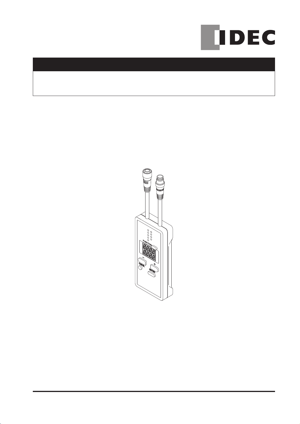
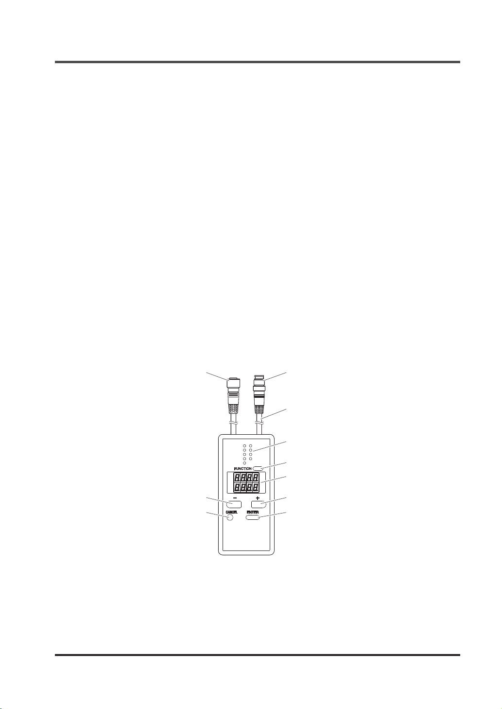
2-2 Part Descriptions
Female connector
- switch
-
CANCEL
FUNCTION
ENTER
Male connector
Cable (0.5m)
FUNCTION indicator × 9
(Green)
FUNCTION switch
Digital display (Red)
+
+ switch
ENTER switchCANCEL switch
6
Page 8
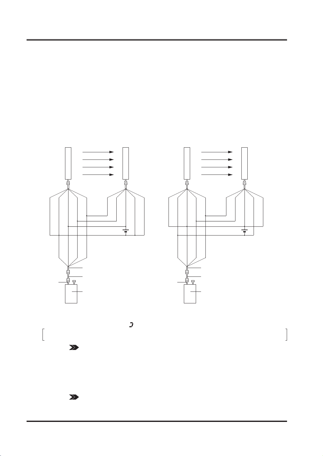
Connecting / Setting Procedures
2-3 Connecting / Setting Procedures
This section describes the connecting / setting procedures for both this device and SE4D series.
1. Set the SE4D series, and check that the
SE4D series works properly. For mounting
method of SE4D se r i e s , re f e r to th e
Instruction Manual.
2. Tur n OF F th e po wer and conne ct t his
device to the SE4D series. Use the handy
controller connection cable (SE9Z-WNC1)
for the connection. The handy controller
connection cable (SE9Z-WNC1) can be
co nnec ted by conn ecting the incl ude d
SE9Z-CCJ02-HC1 to the device’s female
connector.
<For PNP output> <For NPN output>
(Shield)
Female
connector
Emitter
(Blue)
(Blue)
(Orange
(Brown)
(Brown)
/ Black)
(Orange)
24V±10%
(Orange)
(Orange
/ Black)
Handy controller connection
cable (SE9Z-WNC1)
SE9Z-CCJ02-HC1
This device
(Orange / Black)
Receiver
(Brown)
(Orange)
+
-
(Blue)
(Shield)
Female
connector
(Blue)
(Shield)
(Blue)
Emitter
(Orange
(Brown)
(Brown)
/ Black)
(Orange)
(Orange)
(Orange
Handy controller connection
cable (SE9Z-WNC1)
SE9Z-CCJ02-HC1
This device
(Orange / Black)
24V±10%
/ Black)
Receiver
(Brown)
(Orange)
+
-
(Blue)
(Shield)
3. Turn ON the power, and set the function with this device.
After the power of this device is ON, approx. 30 sec. will be taken for data transmission with SE4D
series. While data transmission, “
” lights up in revolving.
The control output (OSSD 1 / 2) of SE4D series is set to “OFF” while this device has been
connected.
REFERENCE Refer to “3-1 Functional Descriptions” for the details of the functions, and refer to “3-2
Function Setting (Operation Procedure)” for the setting procedures of the functions
respectively.
4. Turn OFF the power, then remove this device.
5. Check that the SE4D series works as set at the procedure 3.
Then, inspect the SE4D series.
REFERENCE Refer to “Chapter 4 Maintenance” of the SE4D series instruction manual for the details of
the inspection of the SE4D series.
7
Page 9
CHAPTER 3 FUNCTIONS
3-1 Functional Descriptions
If conguration of the system is changed (replace the SE4D series etc.), set the function
again.
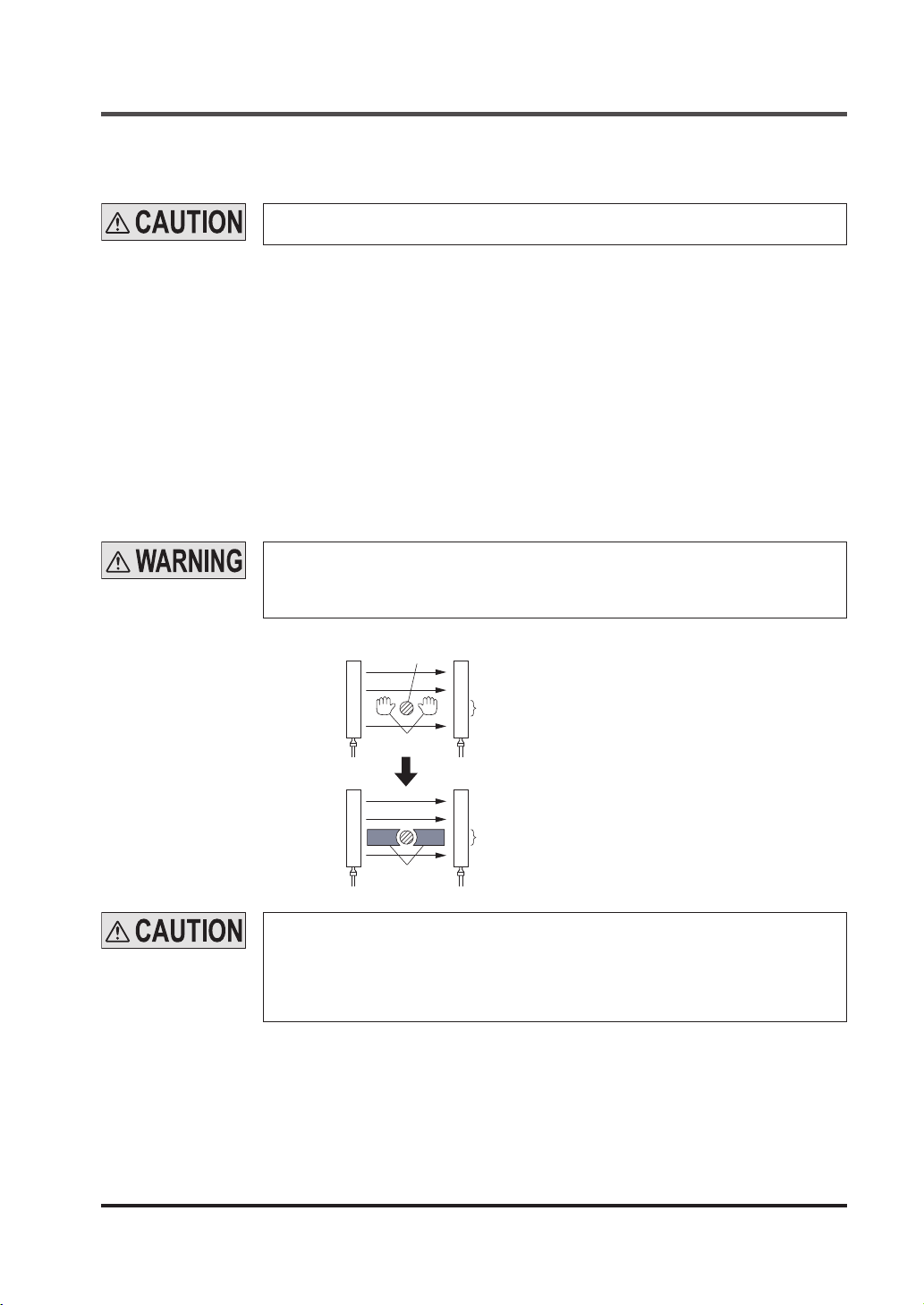
3-1-1 Fixed Blanking Function
This is a function that the control output (OSSD 1 / 2) of SE4D series is not turned OFF, even if the
specied beam channel(s) is blocked OFF.
This is useful when an obstacle always blocks OFF the specic beam channel(s).
There are “Clear,” “Auto” and “Manual” for the setting method.
● Clear setting : The xed blanking function is to be invalid (factory setting).
● Auto setting : The currently blocked OFF beam channels are set as “effective beam channels”
in the xed blanking function. Be sure to set this function in the state where the
emitter emits light. Furthermore, this function cannot be set in the state where all
beam channels receive lights / are blocked.
● Manual setting : Each beam channel can be set to “effective / ineffective” in the fixed blanking
function respectively.
When the xed blanking function is used, the control output (OSSD 1 / 2) of SE4D series
is not turned OFF even if the particular beam channels are blocked.
By using a protection structure etc., make the dangerous parts of the machine inaccessible
to personnel through the sensing area of the particular beam channels.
<Before measures>
<After measures>
When the effective beam channel(s) in the xed blanking function receive(s) the beam(s)
from the emitter, the control output (OSSD 1 / 2) of the SE4D series is xed to “OFF.” In
this case, check the mounting condition and turn the power ON again.
(Even if the power is turned ON again, the xed blanking function still stays effective.)
When the xed blanking function is used, the received light intensity indicator of SE4D
series is turned OFF regardless of the received light intensity.
Obstacle
Emitter
Dangerous area
Emitter
Protection structure
Beam channels the xed blanking
function has been set to ON
Receiver
Beam channels the xed blanking
function has been set to ON
Receiver
8
Page 10

Functional Descriptions
3-1-2 Floating Blanking Function
This function is set in each SE4D series.
If the number of the blocked beam channels is less than the set number of the beam channels, the
control output (OSSD 1 / 2) of SE4D series is not turned “OFF.”
This function is useful when an obstacle moves within the sensing area.
The factory setting of this function is “ineffective.”
The following items can be set.
Set number of beam channels
● Selectable among 0 (the oating blanking function is ineffective), 1, 2 or 3.
Ineffective setting of both end beam channel
● “Effective / ineffective” of the oating blanking function for the both end beam channels can be
selected.
• SET (Effective) : The floating blanking function becomes ineffective for the both end beam
channels. In case either end of the beam channel is blocked, the control
output (OSSD 1 / 2) of SE4D series is turned “OFF” regardless of the set
number of the beam channels.
• CLR (Ineffective) : The floating blanking function becomes effective for all beam channels
including both end beam channels.
Non-serial beam channel setting
• SET (Effective) : Even if the beam channels are blocked discontinuously in the set beam
channels, the control output (OSSD 1 / 2) of SE4D series is turned “ON.”
(Discontinuous mode)
• CLR (Ineffective) : When the beam channels are blocked discontinuously even in the set beam
channels, the control output (OSSD 1 / 2) of SE4D series is turned “OFF.”
(Continuous mode)
● When using the floating blanking function, the size of the minimum sensing object
becomes larger, and the safety distance is longer as well. For the calculation of the
safety distance, refer to the instruction manual enclosed with SE4D series.
● Before designing the system, refer to the relevant laws and standards of the region
where SE4D series is to be used and then install SE4D series.
● The minimum sensing object differs depending on the set number of the beam channels.
[For use in Europe (EU) (as EN 999)] (Also applicable to ISO 13855)
(For intrusion direction perpendicular to the sensing area)
<In case that the minimum sensing object is ø40mm or less>
● Equation S = K × T + C
S : Safety distance (mm)
Minimum required distance between the sensing area surface and the dangerous parts of
the machine.
K : Intrusion velocity of operator’s body or object (mm/sec.)
Taken as 2,000 (mm/sec.) for calculation
T : Response time of total equipment (sec.)
T = T
m
+ T
SE4D
Tm: Maximum halting time of machine (sec.)
T
: Response time of SE4D series (sec.)
SE4D
C : Additional distance calculated from the size of the minimum sensing object of the SE4D
series (mm)
However, the value of C cannot be under 0.
C = 8 × (d - 14)
d: Diameter of the minimum sensing object (mm)
9
Page 11

Functional Descriptions
<Minimum sensing object>
Floating blanking function
Others
Effective
Shielded
Lockout
ON
OFF
OFF
ON
Ineffective
SE4D-H□ ø25mm ø45mm ø65mm ø85mm
If the oating blanking function is used, the incident light intensity indicator is turned OFF
when an obstacle exists in the sensing range regardless of the incident light intensity.
1 beam channel 2 beam channels 3 beam channels
3-1-3 Auxiliary Output Switching Function
This function changes the operation state of the auxiliary output. It is useful when desired to make an
indicator to operate or inform the operation state of the SE4D series to PLC.
Do not use the auxiliary output for the purpose of stopping the machine in which the SE4D
series is installed. Failure to do so could result in death or serious injury.
The following settings are selectable.
Operation of the auxiliary output corresponding to SE4D series state
Setting
mode
0
1
2 ON when emitting OFF ON OFF
3 OFF when emitting ON OFF ON
4
5
6 ON during muting OFF
7 OFF during muting ON
8
9
Notes: 1) When the xed blanking function, the oating blanking function or the muting function is used, the setting of ON / OFF
2) By the setting of ON / OFF in light receiving condition, light-receiving / light interrupted condition is output regardless of
<e.g.>
When the fixed blanking function is used, if an obstacle exists in the set area and other area is in light receiving
3) The state of the auxiliary output remains the same even if the SE4D series state changes.
Auxiliary output setting
Negative logic of the control
output (OSSD 1 / 2)
(factory setting)
Positive logic of the control
output (OSSD 1 / 2)
OFF under unstable light
receiving condition (Note 1)
ON under unstable light
receiving condition (Note 1)
ON in light receiving condition
(Note 2)
OFF in light receiving condition
(Note 2)
under unstable light-receiving condition does not work.
the xed blanking function, the oating blanking function or the muting function.
condition, the control output (OSSD 1 / 2) is in ON sate, however, the auxiliary output becomes OFF since the SE4D
series has been detecting the obstacle.
Emission
halt
ON
OFF
(Note 3) OFF ON (Note 3) (Note 3)
(Note 3) ON OFF (Note 3) (Note 3)
OFF ON OFF OFF
ON OFF ON ON
State of sensing area when emitting
Unshielded
Unstable
light-receiving
condition
OFF when OSSD is ON
ON when OSSD is OFF
ON when OSSD is ON
OFF when OSSD is OFF
ON during muting
Others: OFF
OFF during muting
Others: ON
10
Page 12
Functional Descriptions
3-1-4 Emission Intensity Control Function
This function reduces the emitting intensity.
It is useful for preventing interference from the emitter to the other devices.
Emission intensity control
• CLR (Ineffective) : Operating range is 0.3 to 9m for SE4D-H□ (12 to 64 beam channels), 0.3 to
7m for SE4D-H□ (72 to 96 beam channels) (factory setting).
• SET (Effective) : The operating range is reduced by approx. 50%.
3-1-5 Copy Function
This is a function to copy the setting of a SE4D series to other SE4D series.
This function is available only under the same system configuration (the number of sensors, the
number of beam channels, same model No.).
All functions that are settable with this device can be copied.
Note that the password is also copied with this function.
The following operations are available with this function.
● Upload : Upload the functional setting data of SE4D series to this device.
● Download : Download the functional setting data of this device to SE4D series.
● Monitoring : Check the functional setting data saved in this device.
Upload
This device
(Storage area for SE4D series)
Download
SE4D series
Original
SE4D series
Copied
SE4D series
Copied
3-1-6 Muting Setting Changing Function
The setting of the muting function can be changed.
Setting of the muting function on each beam channel
● Each beam channel can be set to “effective / ineffective” in the muting function respectively. (Note)
● The factory setting of this function is effective for all beam channels.
Note: If the beam channel set to ineffective in the muting function is blocked, the control output (OSSD 1 / 2) becomes “OFF” and
the muting function is canceled.
● There are two setting methods, “Auto” and “Manual” to set muting beam channel.
• Auto setting : The beam channel which is currently blocked is set as the “effective” beam
channel. When all beam channels are in light receiving condition, the setting is
not accepted. Furthermore, in the state where emission is halted or all beam
channels are blocked, the all beam channels become “effective” in the muting
function.
• Manual setting : Each beam channel can be set to “effective / ineffective” in the muting function.
ON: The muting function is effective
OFF: The muting function is ineffective
11
Page 13

Functional Descriptions
Muting input conditions
● The order for inputting the muting input A and B, which the muting function activates, can be set.
A = b: Effective even either comes rst
A b: Effective only when the input A comes rst
b A: Effective only when the input B comes rst
Note: The setting is possible for each channel.
Setting of the muting lamp diagnosis function
● The muting lamp diagnosis function can be set to “effective / ineffective.” (Note)
The factory setting of this function is effective.
ON : The muting lamp diagnosis function is effective.
OFF : The muting lamp diagnosis function is ineffective.
Note: If the muting lamp diagnosis function is set to ineffective, the muting function is maintained even if the lamp blew.
Muting sensor output operation setting
● Output operation of the muting sensor can be selected.
The factory setting is NONO (Normally Open, Normally Open).
• NONO (Normally Open, Normally Open)
A muting sensor which is to be connected to the muting input A (ON with light non-received
status, ON with object approaching status and ON with object contacted status)
A muting sensor which is to be connected to the muting input B (ON with light non-received
status, ON with object approaching status and ON with object contacted status)
• NONC (Normally Open, Normally Closed)
A muting sensor which is to be connected to the muting input A (ON with light non-received
status, ON with object approaching status and ON with object contacted status)
A muting sensor which is to be connected to the muting input B (ON with light received status,
ON with object non-approaching status and ON with object non-contacted status)
3-1-7 Interlock Setting Changing Function
One condition can be selected from the following three interlock conditions. It can be set to invalid,
too. (Mode 3)
• Start / Restart interlock (Mode 0)
The SE4D series goes into interlock condition after the power is ON and when it is in the light
receiving condition.
The factory setting is Start / Restart interlock.
• Start interlock (Mode 1)
The SE4D series goes into interlock condition only when the power is ON. Once the SE4D
series is reset, it does not go into interlock condition again.
• Restart interlock (Mode 2)
The SE4D series does not go into the interlock condition when the power is ON.
series goes into interlock condition only when the SE4D series receives the light, after the
power is ON, the control output (OSSD 1 / 2) is turned into ON once and then the SE4D series
is blocked.
The SE4D
3-1-8 External Device Monitor Setting Changing Function
The setting of the external device monitor can be changed.
1. Allowable period of the response time: 100 to 600ms (unit of 10ms)
The factory setting is 300ms.
2. “Effective / ineffective” of the external device monitor function can be selected.
The factory setting is “effective.”
12
Page 14

Functional Descriptions
3-1-9 Protective Function
The functional settings are not allowed to change without the input of a password.
When the protective function is set to “effective,” the setting can be changed by inputting the password.
The setting contents monitor function can be used regardless of the protective function “effective / ineffective.”
The password should be a 4-digit number from 0 to 9. (The password of the factory setting is “0000.”)
The protective function is set on the receiver side.
● When the protecting function is set to “ineffective,” the third person may change the
setting. It is recommended that the protecting function should be set to “effective” so as
not to change the setting by the third person.
● Take sufcient care not to forget the set password. In case you forget the password,
please contact us.
3-1-10 Initialization Function
The settings can be initialized. (factory setting) (Note)
The factory setting of each function is as follows.
Function Setting
Fixed blanking function Ineffective
Floating blanking function Ineffective
Auxiliary output switching function Mode 0
Emission intensity control function Normal mode
Mu ti ng s et ting
c h a n g i n g
function
Interlock setting changing function Start / Restart
External devise monitor setting changing function Effective / 300ms
Override setting changing function 60 sec.
Note: The setting of the protective function and the setting data of the copy function are not initialized.
Setting of the muting function on each beam channel Effective for all beam channels
Muting input conditions A = B
Setting of the muting lamp diagnosis function Effective
Muting sensor output operation setting NONO
3-1-11 Setting Contents Monitoring Function
Each setting of the SE4D series can be monitored. The following can be monitored.
● Model No. / the number of beam channels
● Setting of the xed blanking function (Reading out the record of the latest 5 times is possible)
● Setting of the oating blanking function (Reading out the record of the latest 5 times is possible)
● Setting of the auxiliary output switching function
● Setting of the emission intensity control function
● Setting of the muting setting changing function
(Reading out the record of the latest 5 times is possible, however, only for setting beam channel.)
● Setting of the interlock setting changing function
● Setting of the external device monitor setting changing function
● Override setting changing function
3-1-12 Override Setting Changing Function
Maximum continuous effective time set at the override function can be changed.
The maximum continuous effective time can be set in the range of 60 to 600 sec. (in units of 10 sec.).
The factory setting is 60 sec.
13
Page 15
3-2 Function Setting (Operation Procedure)
This section describes the setting of each function (operation procedure).
<Selecting the setting item>
Select a setting item with FUNCTION or CANCEL switch, and conrm it with ENTER.
key operation
* * * *
* * * *
To “3-2-1 Fixed Blanking Function”
To “3-2-2 Floating Blanking Function”
Function Setting
: FUNCTION
: ENTER
: CANCEL
: : +
* * * *
* * * *
* * * *
* * * *
* * * *
* * * *
* * * *
To “3-2-3 Auxiliary Output Switching Function”
To “3-2-4 Emission Intensity Control Function”
To “3-2-5 Copy Function”
To “3-2-6 Muting Setting Changing Function”
To “3-2-7 Interlock Setting Changing Function”
To “3-2-8 External Device Monitor Setting Changing Function”
To “3-2-9 Protective Function”
To “3-2-10 Initialization Function”
To “3-2-11 Setting Contents Monitoring Function”
To “3-2-12 Override Setting Changing Function”
“****” indicates the connection state of the system.
● “
”: Used when connected to the SE4D series.
14
Page 16

Function Setting
<Inputting a password>
When the protective function is effective, “Lock” is shown on the lower section of the digital display.
The functional settings of the SE4D series cannot be changed unless the password is input.
“3-2-9 Protective Function” is “locked” even when the protective function is ineffective.
1) “3-2-11 Setting Contents Monitoring Function” is not “locked.”
Remarks
2) Once the password is input, you do not need to input the password again till the power is
turned OFF. (Except “3-2-9 Protective Function”) However, if the power is turned ON again
without changing the protective function to ineffective, the password have to be input again
since the protective function is still effective.
The procedure for inputting a password is as follows.
Input password
NG
CH1
Complete inputting password for 1 unit
NG
CH2
Note that
CH3
Complete inputting password for 2 units
NG
Complete inputting password
15
Page 17
Function Setting
<Selecting sensor>
Each function can be set on each SE4D series connected in series as well. Select a SE4D series to
set each function.
Since “3-2-5 Copy Function” and “3-2-9 Protective Function” are set collectively, it is not
necessary to select a sensor. Furthermore, when a SE4D series unit is used, CH2 / CH3 cannot
Remarks
be selected. When two SE4D series in series connection are used, CH3 cannot be selected.
“3-2-3 Auxiliary Output Switching Function,” “3-2-7 Interlock Setting Changing Function” or
“3-2-8 External Device Monitor Setting Changing Function” is set with CH1 only. CH2 and
CH3 are not indicated.
Emitter
Emitter
Emitter
CH3 (Sub sensor 2)
Receiver
CH2 (Sub sensor 1)
Receiver
CH1 (Main sensor)
Receiver
ALL (All sensor) (*)
*: When the units are not in series connection, it is not indicated.
16
Page 18

1. Fixed blanking
Function Setting
3-2-1 Fixed Blanking Function
function
2. To Floating
blanking
function
Select function
(Ineffective)
(Clear setting)
(Effective)
(Auto setting)
(Effective)
(Manual setting)
Select sensor
(All sensors)
(Main sensor)
(Sub sesnor 1)
(Sub sesnor 2)
Manual
setting
Input
password
Once a password
is input, it is not
necessary to input
it again till the
power is turne d
OFF.
(Clear setting) Send
Input
password
(Auto setting) Send
Input
password
Beam channel No.
Select beam channel
First beam
channel
Second beam
channel
OK
NG
OK
NG
Setting
Effective beam
channel
Ineffective beam
channel
(Error)
(Error)
To 1
Select “send”
To 1
Select sensor Check result
(Main sensor)
To 1
(Sub sensor 1)
(Sub sensor 2)
Send
OK
NG
(Effective)
(Ineffective)
Keep pressing
switch OK
It is possible to
check ON / OFF of
all beam channels
To 1
(Error)
To 2
key operation
*: The functional setting for each beam channel is as follows.
on : The xed blanking function is effective.
oFF : The xed blanking function is ineffective.
17
: FUNCTION
: ENTER
: CANCEL
: : +
Beam channel No.
The beam channel No. is given with 1, 2, 3・・・from
the bottom.
3
Emitter
2
Beam channel
No.
1
Receiver
Page 19

3-2-2 Floating Blanking Function
To 2
2. Floating blank ing function
3. To Auxiliary
output switching
function
Sensor selection
(Note)
(All sensors)
(Main sensor)
(Sub sensor 1)
(Sub sensor 2)
Set No. of beam channel
Input
password
(Ineffective)
One beam
channel effecive
Two beam
channel effecive
Three beam
channel effecive
Send
Ineffective setting
for both ends
beam channels
(Effctive)
(Ineffctive)
OK
NG
(Error)
Sett ing for
non-ser ial b eam
channel
(Effctive)
(Ineffctive)
Function Setting
To 2
Send
OK
NG
(Error)
key operation
: FUNCTION
: ENTER
: CANCEL
: : +
FLO1 <Effective setting of beam channel>
0: Ineffective
1: 1 beam channel setting
2: 2 beam channels setting
3: 3 beam channels setting
FLO2 <Ineffective setting of both end beam channel>
SET (Effective) : Both ends of the beam channels are not subject to the oat blanking function
CLR (Ineffective) : All beam channels are subject to the oating blanking function
FLO3 <Non serial beam channel setting>
SET (Effective) : Non-serial beam channel mode
CLR (Ineffective) : Serial beam channel mode
Note: When “all sensors” is selected in the sensor selection, the setting of the oating blanking function on each SE4D series
should be identical.
18
Page 20

Function Setting
3-2-3 Auxiliary Output Switching Function
3. Auxiliary output
switching function
Input password (*)
4. To Emission intensity
control function
*: When two or more SE4D series are connected, cancel the protective function of all SE4D series.
<Setting of the auxiliary output>
Mode 0: Negative logic of the control output (OSSD 1 / 2) (factory setting)
Mode 1: Positive logic of the control output (OSSD 1 / 2)
Mode 2: ON during emission, OFF when emission is not done.
Mode 3: OFF during emission, ON when emission is not done.
Mode 4: OFF when the received light level is unstable (Note 1)
Mode 5: ON when the received light level is unstable (Note 1)
Mode 6: ON during muting
Mode 7: OFF during muting
Mode 8: ON in the light receiving condition
Mode 9: OFF in the light receiving condition
Notes: 1) This cannot be used when the xed blanking function, the oating blanking function or the muting setting changing
2) When using with SE4D series only, if the external device monitor function is not used, set the monitor setting to
function is used.
ineffective in “3-2-8 External Device Monitor Setting Changing Function.”
Select output
(Mode 0)
(Mode 1)
(Mode 2)
・・・
(Mode 9)
Send
OK
NG
To 3
(Error)
key operation
: FUNCTION
: ENTER
: CANCEL
: : +
19
Page 21

Function Setting
3-2-4 Emission Intensity Control Function
4. Emission
intensity con-
trol function
5. To Copy
function
<Emission intensity control>
CLR (Ineffective) : Operating range is 0.3 to 9m for SE4D-H□ (12 to 64 beam channels), 0.3 to 7m
SET (Effective) : The operating range is reduced by approx. 50%.
Select sensor
(All sensors)
(Main sensor)
(Sub sensor 1)
(Sub sensor 2)
Emission intensity control
Input
pass-
word
(Ineffective)
(Effective)
Send
OK
NG
To 4
(Error)
key operation
: FUNCTION
: ENTER
: CANCEL
: : +
for SE4D-H□ (72 to 96 beam channels) (factory setting).
20
Page 22

Function Setting
Confirm function
3-2-5 Copy Function
5. Copy function
Input
password
6. To Muting setting
changing function
Select function
(Download)
(Upload)
of system device
* * * *
Check function
* * * *
Select sensor
Receive
Receive
OK
NG
(Error)
OK
NG
Select item
(Error)
To 5
To 5
Detail display
(Only for SET)
key operation
: FUNCTION
: ENTER
: CANCEL
: : +
(Monitor)
“****” indicates the connection state
of the system.
● “
”: Used when connected
to the SE4D series.
*1: The setting of the relay monitor
is as follows.
When set to ineffective: CLR
When set to effective: Set time
(100 to 600ms, in units of 10ms)
*2: The override function can be set
in the range of 60 to 600 sec. (in
units of 10 sec.)
Note: The indication is on the main sensor
(CH1) only.
Fixed blanking effective
/ ineffective display
Floating blanking effective
/ ineffective display
(Emission intensity control)
(Note)
(Auxiliary output)
(Protection)
(Input mode)
(Note)
(Interlock)
(Note)
(Relay monitor) *1
(Note)
(Override)*2
Detail display
(Only for SET)
(Set beam channels)
Both ends beam
channel ineffective setting
Non-serial
beam channel
setting
Muting sensor
output operation
setting
(Note)
(Effective)
(Ineffective)
・・・
Keep pressing switch OK
Muting lamp
diagnosis
function setting
(Note)
Detail display
(Only for SET)
(Effective)
(Ineffective)
・・・
Keep pressing switch OK
21
Page 23

3-2-6 Muting Setting Changing Function
6. Muting setting
changing
function
7. To Interlock
setting chang-
ing
function
Muting setting
(Initialize) (Note 1)
(Auto setting)
Select sensor
MENU setting
Input
password
Select beam
channel
First beam channel is effective
Second beam channel is effective
Beam channel No.
Set Set
Effective beam
channel
Ineffective beam
channel
Function Setting
Muting lamp diagnosis
setting (Note 2)
A←→B in
order of input
A→B in
order of input
(Effective)
(Ineffective)
(Manual setting)
Muting lamp
diagnosis
function setting
(Note 2)
Muting lamp
diagnosis
function setting
(Effective)
(Ineffective)
Muting sensor output
operation setting
AUTO setting
Input
password
Select “send”
Select “send”
Keep pressing switch OK
Select “send”
OK
NG
(Error)
OK
OK
NG
(Error)
To 6
B→A in
order of input
Select sensor Check result
(Main sensor)
To 6
(Sub sensor 1)
To 6
(Sub sensor 2)
To 7
(Effective)
(Ineffective)
Keep pressing switch OK
It is possible to
check ON / OFF of
all beam channels
Muting sensor
output operation
setting
(NONO)
(NONC)
NG
To 6
(Error)
key operation
: FUNCTION
: ENTER
: CANCEL
: : +
Beam channel No.
The beam channel No. is given with 1, 2, 3・・・from
the bottom.
3
Emitter
Beam channel
No.
2
1
Receiver
22
Page 24

Function Setting
*: The functional setting of each beam channel is as follows.
on : The muting function is effective.
oFF : The muting function is ineffective.
● CLR initializes the all settings. (factory setting)
• All beam channels: Effective
• Input condition: A = b
• Muting lamp diagnosis function setting: Effective
● When changing only the setting of the muting input condition, set it by manual setting.
The input condition can be set at SE4D series respectively.
● When initializing only the beam channel that the muting is effective, set to the auto setting in the
emission halt condition.
Notes: 1) “ALL” is displayed only when set by “Auto.”
2) Set the muting lamp diagnosis function on all SE4D series.
However, if the function has been set through CLr / Auto / ManU on each SE4D series, set the function on the SE4D
series.
23
Page 25

Function Setting
3-2-7 Interlock Setting Changing Function
7. Interlock setting
changing function
Input
password
8. To External device
monitor setting
changing function
*: When two or more SE4D series are connected, cancel the protective function of all SE4D series.
<Setting of the interlock>
Mode 0: Start / restart interlock function (factory setting)
Mode 1: Start interlock function
Mode 2: Restart interlock function
Mode 3: Ineffective
Setting selection
(Mode 0)
(Mode 1)
(Mode 2)
(Mode 3)
Send
OK
NG
To 7
(Error)
key operation
: FUNCTION
: ENTER
: CANCEL
: : +
24
Page 26

Function Setting
3-2-8 External Device Monitor Setting Changing Function
8. External device
monitor setting
changing function
9. To Sub display
function / Protect
function
Input password
Relay monitor setting
(Ineffective)
(Effective)
Time setting
(100ms)
(110ms)
(120ms)
・・・
(600ms)
Send
OK
NG
To 8
(Error)
key operation
: FUNCTION
: ENTER
: CANCEL
: : +
*: When two or more SE4D series are connected, cancel the protective function of all SE4D series.
<External device monitor>
CLR (Ineffective) : The external device monitor function is ineffective.
SET (Effective) : The external device monitor function is effective. (The factory setting is 300ms.)
25
Page 27

3-2-9 Protective Function
9. Sub display
function / Pro tect function
10. To Sub dis play function
/ Initialization
function
*: When the units are connected in series, the indication is as follows.
CH1: “
CH2: “
CH3: “
Select sensor
(All sensors)
(Main sensor)
(Sub sensor 1)
(Sub sensor 2)
Select function
Input
password
(Ineffctive)
(Eeffctive)
(Change password)
Send
Input new
password (*)
Increase /
decrease
the No. with
OK
NG
”
”
”
(Error)
To 9
Function Setting
key operation
Send
OK
NG
(Error)
: FUNCTION
: ENTER
: CANCEL
: : +
To 9
26
Page 28
Function Setting
3-2-10 Initialization Function
10. Sub display
function /
Initialization
function
11. To Sub dis play function
/ Setting con tents moni-
toring function
Select sensor
(All sensors)
(Main sensor)
(Sub sensor 1)
(Sub sensor 2)
Input
password
Confirm
Send
OK
NG
To 10
(Error)
key operation
: FUNCTION
: ENTER
: CANCEL
: : +
27
Page 29

3-2-11 Setting Contents Monitoring Function
11. Sub display
function / Set ting contents
monitoring
function
Select sensor
Fixed blanking
function
Function Setting
Detail display
(Only for SET)
12.
To Sub display
function / Over ride setting
changing
function
(Main sensor)
(Sub sensor 1)
(Sub sensor 2)
Fixed blanking
function
Floating blanking
function
Floating blanking
function
(Emission intensity control function)
(Effective)
(Note)
(Auxiliary output switching function)
(Positive logic of OSSD)
(Protect function)
(Effective)
Muting setting
changing function
(Note)
Interlock setting
changing function
(Mode 1)
(Current setting)
(Record 1)
(Record 5)
Muting sensor
output operation
setting
(NONO)
・・・
Detail display
(Only for SET)
(Effective)
(Effective)
Keep pressing switch OK
Muting on each
beam channel
Muting lamp
diagnosis
function setting
(Effective)
(Current setting)
(Current setting)
(Record 1)
・・・
(Record 5)
(Record 1)
・・・
(Effective)
(Ineffective)
Keep pressing switch
OK
Beam channel display of the
record 0 (Only for SET)
(Effective)
(Ineffective)
Keep pressing switch OK
(Note)
CLR,
*:
100 to 600 (unit of 10)
*:
60 to 600 (unit of 10)
External device monitor
setting changing function
(Effective)
(Note)
Override setting
changing function
(Model No.)
(No. of beam channel)
Note: The indication is on the main sensor (CH1) only.
(Record 5)
key operation
: FUNCTION
: ENTER
: CANCEL
: : +
28
Page 30

Function Setting
3-2-12 Override Setting Changing Function
12. Override setting
changing function
Input password
9. To Sub display
function / Protect
function
*: When two or more SE4D series are connected, cancel the protective function of all SE4D series.
Note: The factory setting is 60 sec.
Time setting
(60 sec.)
(70 sec.)
(80 sec.)
・・・
(600 sec.)
Send
OK
NG
To 12
(Error)
key operation
: FUNCTION
: ENTER
: CANCEL
: : +
29
Page 31

CHAPTER 4 TROUBLESHOOTING
Symptoms Cause Remedy
Control output (OSSD
1 / 2) is not turned ON.
Error indication Cause Remedy
Note: The factory setting of the SE4D series password is “0000.”
This devi ce is co nnected to the SE4D
series.
The fixed blanking function is set in all
lights received / all l i g h t s blocked
condition, or the muting function is set in
all lights received condition.
The copy function is used for the units
having different system conguration from
each other (the number of sensors / the
number of beam channels / model No. is
not same).
In the copy function, download the data
without uploading.
The password does not match.
Sensor communication error 1
(Model No. is wrong)
Sensor communication error 2
Wrong wiring between the emitter and
receiver.
Sensor communication error 3
Effect from noise or failure of internal
circuit
Failure of EEPROM in this device.
(Failure on device)
Failure of EEPROM in this device.
(Failure on EEPROM data)
Disconnect this device.
Do not set the xed blanking function in all
lights received / all lights blocked condition,
or the muting function in all lights received
condition.
Use the copy function for the units having
identical system conguration.
Upload the data before downloading.
Input the correct password. In case you
forget the password, contact us. (Note)
Connect this device to SE4D series.
Connect the emitter and receiver correctly.
Check the noise state around the SE4D
series.
Contact us.
Contact us.
If this device does not work, press ENTER key or CANCEL key one minute after pressing ENTER
key.
If the device does not work correctly after checking the items above, please consult us.
30
Page 32

CHAPTER 5 SPECIFICATIONS / DIMENSIONS
5-1 Specications
Model No.
Item
Applicable model Light curtain SE4D series
Supply voltage 24V DC±10% Ripple P-P 10% or less (common to sensor power supply)
Current consumption
Communication method
Digital display 4-digit red LED display × 2 (selected beam channels, setting contents etc. are displayed. )
FUNCTION indicator
Fixed blanking function, Floating blanking function, Auxiliary output switching function
Functions
Ambient temperature
Ambient humidity 30 to 85% RH, Storage: 30 to 85% RH
Voltage withstandability
Insulation resistance 20MΩ or more, with 500V DC megger between all supply terminals connected together and enclosure
Cable 8-core shielded cable with a connector on one end 0.5m long (2 pcs.)
Weight Approx. 200g
Note: There may be a case that the copied data through the copy function is deleted due to external causes. After the copy
function was used, check the copied data.
Emission intensity control function, Copy function (Note), Muting setting changing function
Interlock setting changing function, External device monitor setting changing function
Protective function, Initialization function, Setting contents monitoring function and
Override setting changing function
-10 to +55°C (No dew condensation or icing allowed), Storage: -25 to +70°C
1,000V AC for one minute between all supply terminals connected together and enclosure
RS-485 two-way communications (specic procedure)
Green LED × 9 (lights up when each functional setting is ON)
SE9Z-HC
65mA or less
5-2 Dimensions
65
30
(Unit: mm)
31
25.4
23
ø6 cable 0.5m long
140
Page 33

Revision history
First edition January 10, 2012
32
Page 34

(MEMO)
33
Page 35

1. CAUTIONS FOR SAFE USE
(1) The applications shown in the catalogue are only suggestions, and it is Purchaser's sole responsibility to
ascertain the tness and suitability of the Products for any particular application, as well as to abide by
Purchaser's applicable local laws and regulations, if any.
(2)
Never use the Products NOT rated or designated as “SAFETY SENSOR” in any application involving risk to life
or property. When such a use is made by Purchaser, such Purchaser shall indemnify and hold harmless IDEC
from any liability or damage whatsoever arising out of or in relation to such use.
(3) In incorporating the Products to any equipment, facilities or systems, it is highly recommended to employ
fail-safe designs, including but not limited to a redundant +++design, ame propagation prevention design,
and malfunction prevention design so as not to cause any risk of bodily injury, fire accident, or social
damage due to any failure of such equipment, facilities or systems.
(4) The Products are each intended for use only in environments commonly found in manufacturing industry,
and, unless expressly allowed in the catalogue, specification or otherwise, shall not be used in, or
incorporated into, any equipment, facilities or systems, such as those:
(a) which are used for the protection of human life or body parts;
(b) which are used outdoors or in environments subject to any likelihood of chemical contamination or
electromagnetic inuence;
(c) which are likely to be used beyond the limits of operations or environments specied by IDEC in the
catalogue or otherwise;
(d) which may cause risk to life or property, such as nuclear energy control equipment, transportation
equipment (whether on rail or land, or in air or at sea), and medical equipment;
(e) which are operated continuously each day for 24 hours; and
(f) which otherwise require a high level of safety performance similar to that required in those equipment,
facilities or systems as listed in (a) through (e) above.
2. EXPORT CONTROL LAWS
In some jurisdictions, the Products may be subject to local export laws and regulations. If any diversion or re-export is
to be made, Purchaser is advised to abide by such local export laws and regulations, if any, at its own responsibility.
Page 36

7-31, Nishi-Miyahara 1-Chome, Yodogawa-ku, Osaka 532-8550, Japan
IDEC ELEKTROTECHNIK GmbH
Wendenstrasse 331, D-20537, Hamburg, Germany
http://www.idec.com
2012.2
 Loading...