

Page 1
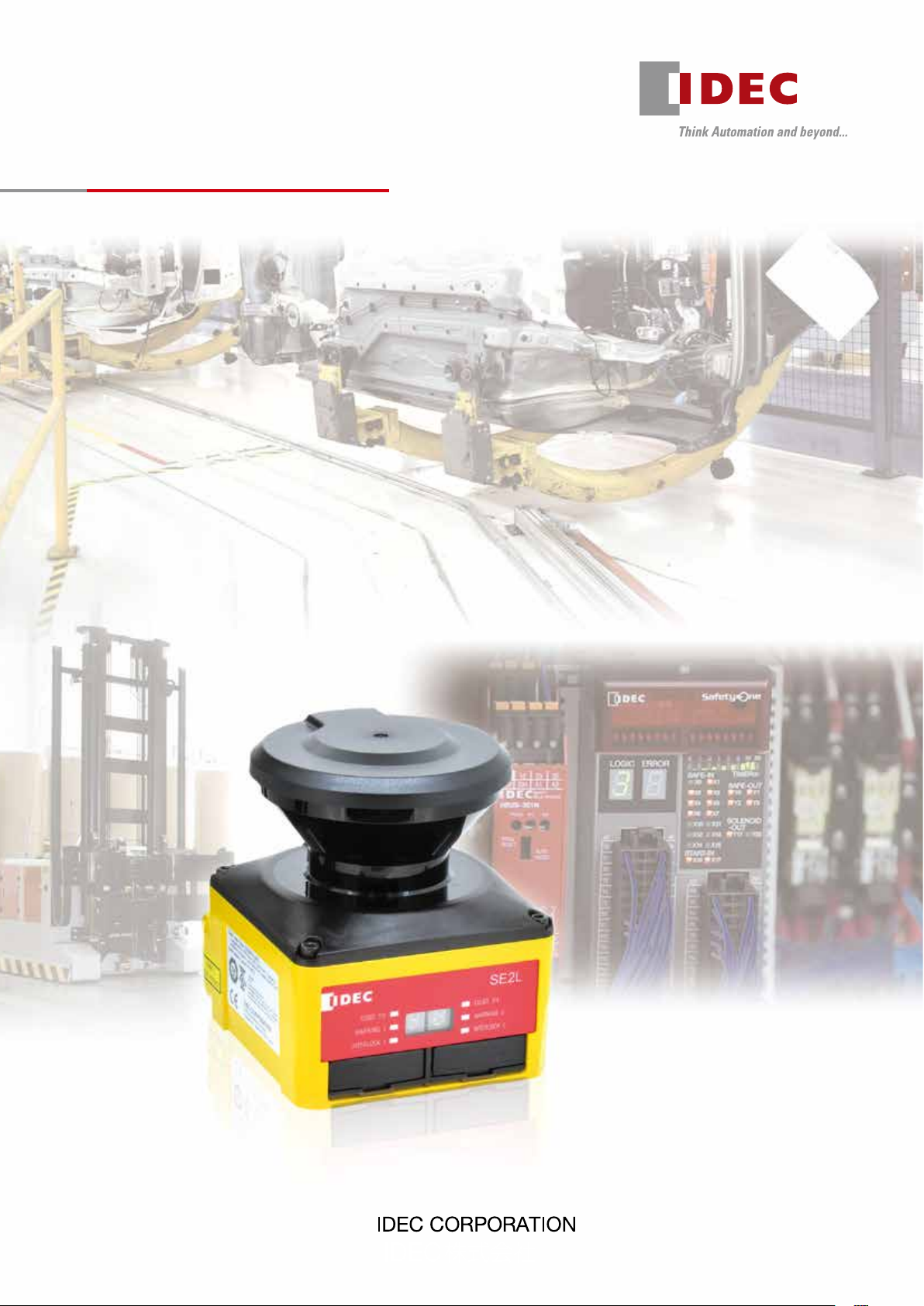
Safety Laser Scanner
SE2L
Page 2
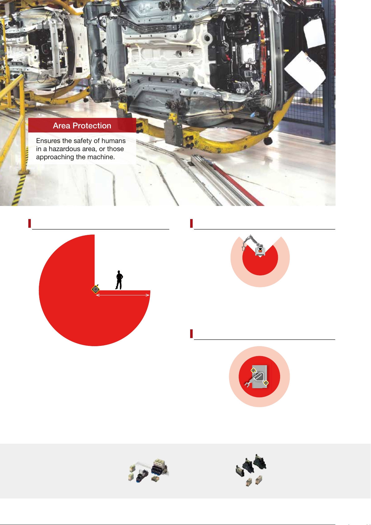
Distance 5m, sensing angle 270º
Area Protection
Ensures the safety of humans
in a hazardous area, or those
approaching the machine.
1
7 steps or more
Ensures productivity and safety
Stop
∗
Low speed
5m
One SE2L protects a wide area (270º and 5m) and
can be used in a variety of applications such as large
sized systems or long conveyor lines.
*
1: average stride length (70 cm) of a 170 cm person
IDEC’s safety products
for safe and productive
production lines
The SE2L is a safety sensor that can detect approach.
Stop area can be made smaller by detecting approach
at the additional protection zone to start slowdown.
(Conventional conguration of one protection zone +
two warning zones is possible)
Master slave function, rst in its industry
A maximum of four SE2Ls can be interconnected using
RS-485 for master/slave operation.
RF2 force-guided relay
(2-pole)
Can be used as interface
relays to send input
signals to a controller, or to
amplify current for driving a
contactor.
RF1V force-guided relay
(4-pole/6-pole)
Can interrupt a small load
directly.
2
Page 3
Dual protection function Ensures safety at positional change
r
!
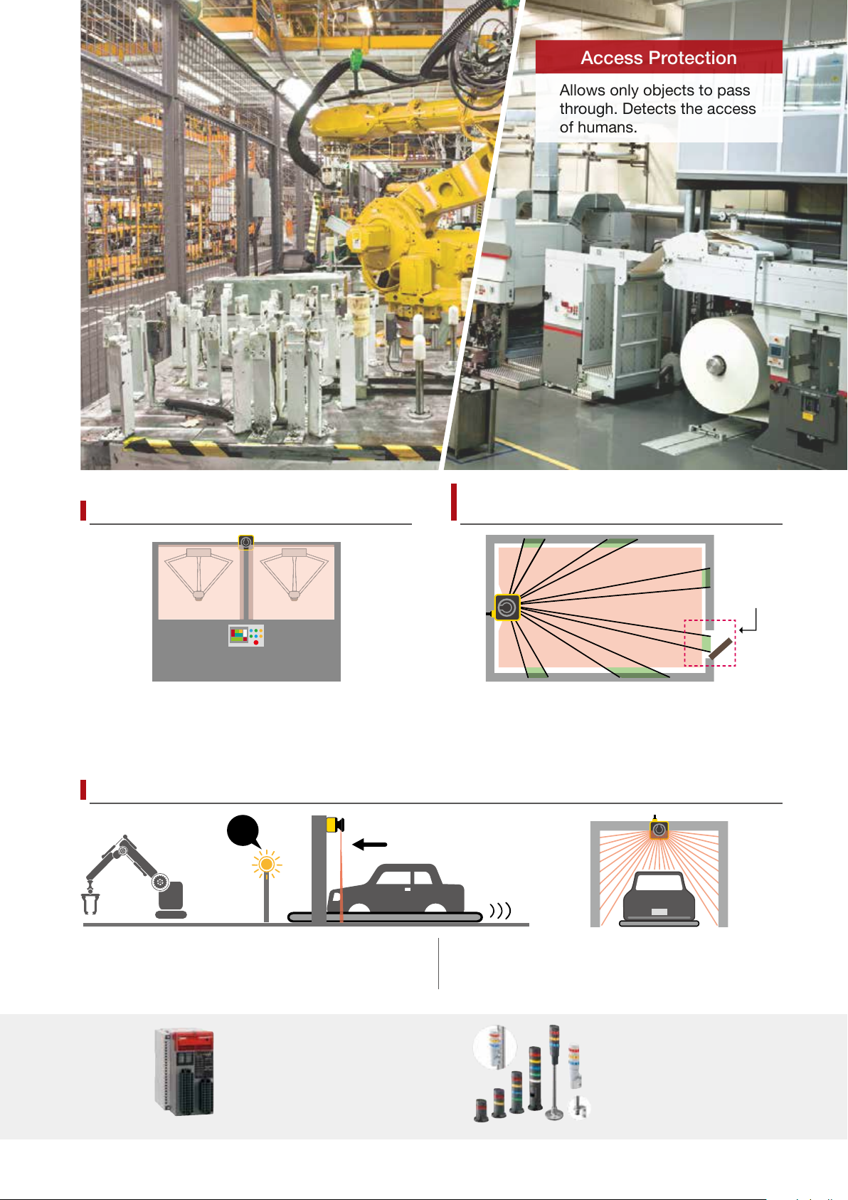
Access Protection
Allows only objects to pass
through. Detects the access
of humans.
Doo
An SE2L can monitor two separate hazardous areas to
stop machines when detecting the access of humans. No
reective sensor is necessary, thus eliminating the need
of optical axis alignment. Can replace two light curtains.
Reference monitoring function ensures safety by
detecting the positional change of SE2L or reference
boundary, such as a door’s opening/closing status.
Ensures safety at entrance of works. Override function enables restart from unintended stop.
By disabling some areas of protection zone, muting
function allows objects to enter the hazardous area
without stopping the machine.
FS1A Safety Controller LD6A LED SignaLight Towers
A variety of safety products can be
connected to the controller equipped
with various control logics.
With override function, when stopped by errors
at muting status, the work can be moved easily.
Used to indicate the status of
processes. Visible even at a distance.
3
Page 4
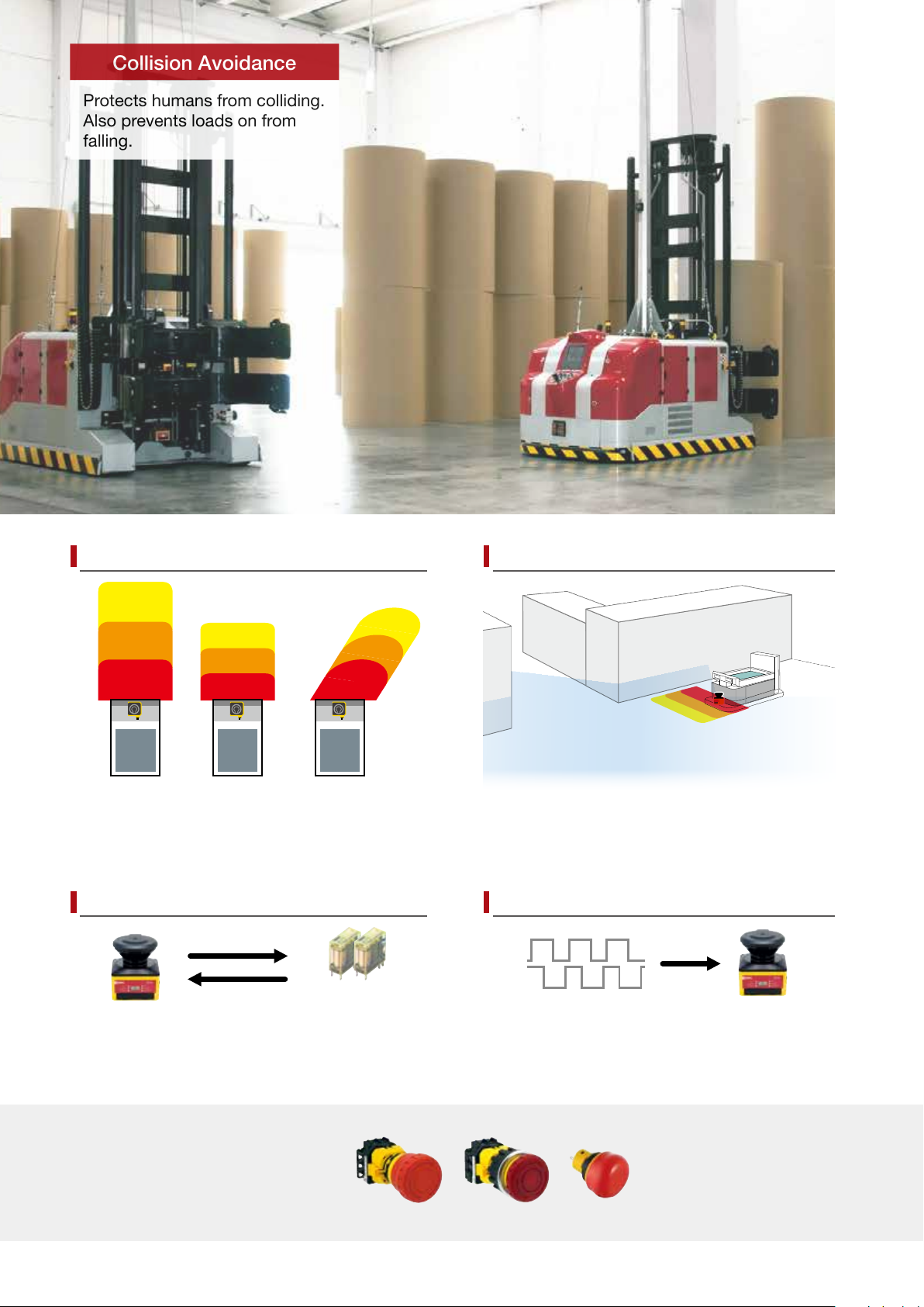
Collision Avoidance
A maximum of 32 area patterns
Protects humans from colliding.
Also prevents loads on from
falling.
Utilize distance measurement data
A maximum of 32 area patterns can be congured/
switched according to the mobile application such
as AGV, ensuring the optimum protection in various
applications.
Monitors external output equipment
EDM function monitors the status of external
devices, enabling monitoring of welded contacts and
such.
IDEC’s safety products
for safe and productive
production lines
4
During safety protection, the SE2L can send out
distance measurement data through the Ethernet
port, in order to obtain the data of the obstacles.
Encoder inputs
Force-guided relay
Pulse signals from an incremental encoder can be sent
to the SE2L directly without a controller, enabling to
switch areas easily depending on the speed.
Emergency Stop Switches
XW/XN/X6
A variety of models to choose from.
Page 5
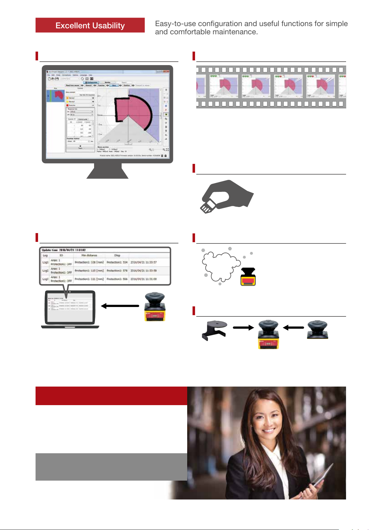
Supports area conguration
Excellent Usability
Easy-to-use conguration and useful functions for simple
and comfortable maintenance.
Check detection status with video
Teaching function enables automatic area
conguration by referring to obstacles such as walls
and columns. Area can be congured easily even
with complicated background.
Detection log report reduces maintenance
No human in the
protection zone
Area data and distance measurement data can be
recorded while monitoring on PC. Video of detection
status can be replayed with the le.
Human approaching
the protection zone
Human inside the
protection zone
Reduce maintenance and start-up time
Area data and function settings
created on PC can be transferred
to the SE2L using not only by
USB cable but also micro SD
card.
Stable operation even in dusty environment
Checks dust in air with signals
and reduces unintended
detection. Safety function is not
impaired.
Operational status is displayed on the SE2L. It can
also be displayed on PC to monitor errors and data
log for easy trouble shooting.
IDEC Safety Solution
− Safety system
− Safety consulting
− Risk assessment
− Safety seminars
IDEC—Committed to creating the optimum safety
environment—both for humans and systems.
Optical window can be replaced on-site
Cover Bracket Optical Window
Optical window can be replaced by the user, reducing
downtime and cost. A cover bracket to protect the SE2L
for damage by collision is also available.
5
Page 6

SE2L Safety Laser Scanner
SE2L Safety Laser Scanner
Model
Name & Shape Cable Length Part No. Remarks
Cable Model
3m
Connector Model
0.3m
SE2L-H05LP
SE2L-H05LPC
Production
monitored
Safety
tested
Functional
Safety
Package Quantity: 1
•Attachment: SLS Project Designer CD
(includes: User's Manual, SLS_Optical Window Adjuster)
•Applicable OS:
Windows XP, 32 bit (SP3 or higher)
Windows 7, 32/64 bit (SP1 or higher)
Windows 8, 32/64 bit
Windows 8.1, 32/64 bit
Windows 10 32/64 bit
Accessories (optional)
Part No. Cable Length Part No. Remarks
Connector Cable
Micro USB Cable
Ethernet Cable
Extension Cable
Base Mounting Bracket
Rear Mounting Bracket
Simple Base Mounting Bracket
Rear Mounting Bracket
Cover Bracket
Optical Window
2m SE9Z-HS2-C002
5m SE9Z-HS2-C005
10m SE9Z-HS2-C010
20m SE9Z-HS2-C020
1m SE9Z-HS2-XCM11
3m SE9Z-HS2-XCD13
10m SE9Z-HS2-XCE010
20m SE9Z-HS2-XCE020
SE9Z-HS2-BK01
SE9Z-HS2-BK02
SE9Z-HS2-BK03
SE9Z-HS2-BK04L
SE9Z-HS2-CM01
SE9Z-HS2-WD01
Package Quantity: 1
•Degree of protection: IP65
•Used with connector model SE2L-H05LPC only.
•Used to connect the SE2L and PC.
•Degree of protection: IP65
•Waterproof L AN cable
•Used to extend the cable length of the SE2L.
•Used to change the vertical angle alignment of the SE2L.
•Adjustable by 15 degrees total (7.5 degrees each direction)
•Material: iron
•Attachment: Four bolts (M5×12)
•Used to change the vertical/horizontal angle adjustment of the SE2L.
•Adjustable by 15 degrees total (7.5 degrees each direction)
•Material: iron
•Attachment: Four bolts (M5×12)
•Attachment: Four bolts (M5×10)
•Attachment: Four bolts (M5×10)
•Used to protect the optical window in combination with base
mounting bracket or rear mounting bracket.
•Material: iron
•Attachment: Four bolts (M5×12)
•Material: polycarbonate
•Attachment: Four bolts (M3×8)
Safety Products
Safety Controller
Name & Shape Part No. Remarks
FS1A-C11S •24 logics
FS1A-C21S •11 logi c s
Force-guided Relay
Name & Shape Part No. Remarks
2-pole
RF2S-*
RF2V-*
4-pole
RF1V-*
6-pole
RF1V-*
*
See product catalogs or IDEC's website for detailed part no.
6
•Force guided contact
mechanism (EN50205
Type A TÜV approved).
LED SignaLight Tower
Name & Shape Part No. Remarks
•Degree of protection:
LD6A-*
IP65
Emergency Stop Switches
Name & Shape Part No. Remarks
ø30mm
ø22mm
ø16mm
XN1E-*
XW1E-*
AB6E-*
•Degree of protection:
IP65
Page 7

SE2L Safety Laser Scanner
Performance Specifications
Part No. SE2L-H05LP/SE2L-H05LPC
Protection Zone 5.0m maximum
Warning Zone (Note 1) 20m maximum (non-safety)
Additional Safety Distance (Note 2) +100 mm
Sensing Characteristics Black reflector sheet (1.8%) to retro-reflector sheet
Sensing
Characteristics
Light Source
Type Type 3 (IEC 61946-1, IEC 61496-3)
Functional Safety SIL 2 (Type B, HFT=1) (IEC 61508)
PFHd
Master Slave Connection 4 maximum
Enclosure
Power Voltage
Power
Consumption
Output
Input
Interface
Environmental
Resistance
Note 1: When the reflectance of object is 90% or above.
Note 2: Additional distance of 200 mm is needed when the SE2L operates under high reflective background.
Note 3: Total current supply of OSSD output and warning output should be below 1.0A.
Note 4: The angle between the sensing plane and the light source should be more than 5 degrees.
Sensing Angle 270°
Minimum Sensing Width
Scan Cycle 30 ms (rotating speed 2,000 rpm)
Scan Area 32 patterns maximum
Response Time
Element Pulse laser diode
Wavelength 905nm
Laser Class Laser class 1 (IEC 60825-1)
Dimensions 80W × 80D × 95H (mm) (cable not included)
Weight (approx.) Cable model: 0.8 kg (incl. cable)/Connector model 0.5 kg
Degree of Protection IP65 (IEC 60529)
Material Body: aluminum diecast / Optical window: polycarbonate
Cable Cable model: 3 m/Connector model 0.3 m
Without Output Load 6W
Maximum (without output load) 50W
OSSD1/2 (safety)
OSSD3 (safety)
OSSD4 (safety)
WARNING1 (non-safety)
WARNING2 (non-safety)
RES_REQ1, RES_REQ2,
MUT_OUT1, MUT_OUT2
Area Switching
(5 inputs × 2 channels)
EDM1/EDM2/MUTING1/MUTING2/
MUTING3/MUTING4/OVERRIDE1/
OVERRIDE2/RESET1/RESET2/
ENC1_A/ENC1_B/ENC2_A/ENC2_B
PC USB2.0 (USB micro type-B connector)
Master Slave RS-485 (cable)
Distance Measurement Data Output Ethernet 100BASE-TX (water proof connector)
Operating Temperature −10 to +50˚C (no freezing)
Storage Temperature −25 to +70˚C (no freezing)
Operating Humidity 95% RH (no condensation)
Storage Humidity 95% RH (no condensation)
Surrounding Light Intensity (Note 4) 1500 lx maximum
Vibration Resistance
Shock Resistance Acceleration: 98 m/s
Outdoor Operation Not permitted
Altitude Below 2,000m
ø30 mm (maximum distance: 1.8m)
ø50 mm (maximum distance: 3.0m)
ø70 mm/ø150 mm (maximum distance: 5.0m)
ON→OFF: 60 to 510 ms
OFF→ON: 270 to 510 ms
-8
(T1=20 years): when master slave function is disabled
7.8×10
1.6×10⁻⁷ (T1=20 years): when master slave function is enabled
24V DC ±10%: power from converter
24V DC −30%/+20%: power from battery
Output type (high side SW)
Output current (maximum: 500 mA) (Note 3)
Leakage current (maximum: 1 mA)
Cable (AWG 26)
Allowable load (L/R=25 ms, C=1μF)
Output type (high side SW)
Output current (maximum: 250 mA) (Note 3)
Leakage current (maximum: 1 mA)
Cable (AWG 28)
Allowable load (L/R=25 ms, C=1μF)
Output type (PNP transistor output)
Output current (maximum: 200 mA)
Leakage current (maximum: 1 mA)
Cable (AWG 28)
Input Resistance: 4.7kΩ
Cable: AWG 28
Frequency: 10 to 55 Hz Sweep: 1 octave/minute
Amplitude: 0.35 mm ±0.05 mm
2
(10G) Pulse duration: 16 ms
7
Page 8

SE2L Safety Laser Scanner
82
124
120
133.5
Dimensions
Safety Laser Scanner
SE2L-H05LP
Scan angle 270°
9
Connection cable
(30)
Ethernet cable (sold separately)
Cover Bracket
SE9Z-HS2-CM01
All dimensions in mm.
90.7
30
95
67.4
80
4-M5 Depth 8
Cable Model
4-M5 Depth 8
Connector Model
54.5
(Sensing Plane)
68
68
Base Mounting Bracket
SE9Z-HS2-BK01
4-ø5.3 SE2L
Mounting Holes
28
3-ø5.3
ø
85
40
33
29.5
17
21
96.2
70
9
4-M5
18
•Used to protect the optical window in combination
25
15
50
80
66
32
(10)
(30)
28
with base mounting bracket or rear mounting bracket.
66
32
28
Cannot be used with simple base mounting bracket or
rear mounting bracket.
Rear Mounting Bracket
SE9Z-HS2-BK02
4-ø5.3
SE2L Mounting Holes
28
130
66
110
(18)
60
68
110
10
48.2 25
45
70
60
25
Simple Base Mounting Bracket
SE9Z-HS2-BK03 (Note 1)
110
92
37
68
15 15
11
Note 1:
•Usewasherswhenfasteningscrews.
•UsetwoM6screwswheninstallingonanaluminumframe.
(1) Position A: M5 screws
4-M5
screws
68
(2) Position B, C, or D: M6 screws
2-M6
screws
±0.1
110
±0.1
110
4-ø5.3
Cover Bracket
Mounting Holes
7.5° 7.5°
36
A
B
C
D
66
68
134
150
Rear Mounting Bracket
SE9Z-HS2-BK04L (Note 1)
(1) Position A: M5 screws
49.5
(2) Position B: M6 screws
2-M6
screws
88
106
32.4
R53
45
50
(93.2)
7.5° 7.5°
32.4
(101.2)
±0.1
48.2 25
45
20
±0.1
106
4-M5 screws
106
4-ø6
91.5
25
61.2
A
B
4-ø5.3
Cover Bracket
Mounting Holes
7.5° 7.5°
8
Page 9

Wiring Examples
a) When using 32 scanning areas (e.g. AGV)
E-STOP
+24VDC
0VDC
OSSD1
OSSD2
OSSD3
OSSD4
IN_A
IN_A
IN_B
IN_B
IN_C
IN_C
IN_D
IN_D
IN_E
IN_E
FG
X0
X1
X2
Controller
FS1A-C11S
X3
Logic 105
X4
X5
Safety
SE2L Safety Laser Scanner
c) When switching 32 scanning areas using an encoder
+24VDC
0VDC
OSSD1
Y0
Y1
OSSD2
EDM1
WARNING1
WARNING2
IN_A
IN_A
IN_B
IN_B
ENC1_A
ENC1_B
ENC2_A
ENC2_B
RES_REQ1
RESET1
FG
RF2
K1
LED
Pilot Light
RF2
K2
SignaLight
w/alarm
COM
IN1
PLC
IN2
Rotary
Encoder 1
Rotary
Encoder 2
LD6A
OUT
IDEC safety products
Safety Controller: FS1A
E-STOP: X series
b) When using muting/override/EDM
+24VDC
0VDC
OSSD1
OSSD2
EDM1
WARNING1
WARNING2
MUT_OUT1
IN_A
IN_A
IN_B
IN_B
MUTING1
MUTING2
OVERRIDE1
RESET1
FG
RF2
K1
RF2
K1
LD6A
SignaLight
w/alarm
OUT
COM
IN1
PLC
IN2
Muting Sensor 1
Muting Sensor 2
IDEC safety products
SignaLight w/alarm: LD6A
PLC: FC6A
LED pilot light: AP22
Force-guided relay: RF2
Muting Lamp
(PNP)
(PNP)
IDEC safety products
SignaLight w/alarm: LD6A
PLC: FC6A
Muting sensor: SA1E
Muting sensor lamp: HW1P-5
Force-guided relay: RF2
9
Page 10

SE2L Safety Laser Scanner
d) When using the master slave function to guard
an AGV or robot
E-STOP
+24VDC
0VDC
OSSD1
OSSD2
WARNING1
WARNING2
IN_A
IN_A
IN_B
IN_B
IN_C
IN_C
IN_D
IN_D
IN_E
IN_E
RES_REQ1
RESET1
RS-485+
RS-485–
+24VDC
0VDC
RS-485+
RS-485–
FG
+24VDC
0VDC
RS-485+
RS-485–
FG
+24VDC
0VDC
RS-485+
RS-485–
FG
FG
LED
Pilot Light
T4
X4
T5
X5
FS1A-C11S
X0
X1
COM
IN1
IN2
IDEC safety products
SignaLight w/alarm: LD6A
PLC: FC6A
LED pilot light: AP22
Safety Controller: FS1A
E-STOP: X series
Safety
Controller
Logic 11C
PLC
OUT
Y0
Y1
LD6A
SignaLight
w/alarm
e) When using the master slave function to guard
multiple hazards and perform partial stops
E-STOP
+24VDC
0VDC
OSSD1
OSSD2
WARNING1
WARNING2
IN_A
IN_A
IN_B
IN_B
IN_C
IN_C
IN_D
IN_D
IN_E
IN_E
RES_REQ1
RESET1
RS-485+
RS-485–
FG
+24VDC
0VDC
OSSD1
OSSD2
WARNING1
WANING2
RES_REQ1
RESET1
RS-485+
RS-485–
FG
+24VDC
0VDC
OSSD1
OSSD2
WARNING1
WANING2
RES_REQ1
RESET1
RS-485+
RS-485–
FG
+24VDC
0VDC
OSSD1
OSSD2
WARNING1
WANING2
RES_REQ1
RESET1
RS-485+
RS-485–
FG
LED
Pilot Light
Pilot Light
Pilot Light
LED
LED
LED
Pilot Light
IDEC safety products
SignaLight w/alarm: LD6A
PLC: FC6A
LED pilot light: AP22
Safety Controller: FS1A
E-STOP: X series
X0
X1
X2
Safety
X3
Controller
X4
FS1A-C11S
X5
Logic 105
X6
X7
X10
X11
COM
IN1
IN2
IN3
IN4
PLC
IN5
IN6
IN7
IN8
OUT1
OUT2
OUT3
OUT4
Y0
Y1
Y2
Y3
LD6A
SignaLight
w/alarm
LD6A
SignaLight
w/alarm
LD6A
SignaLight
w/alarm
LD6A
SignaLight
w/alarm
Input/Output Circuit
OSSD/WARNING Output Circuit Other Output Circuit
OSSD/WARNING outputs are N
channel MOSFET outputs.
+24V
OSSD1
OSSD2
Control
Circuit
OSSD3 / WARNING1
OSSD4 / WARNING2
10
RES_REQ1, RES_REQ2, MUT_OUT1,
MUT_OUT2 outputs are PNP outputs.
+24V
Control
Circuit
RES_REQ1 / MUT_OUT1
RES_REQ2 / MUT_OUT2
Input Circuit
Available for are input, EDM1, EDM2,
RESET1, RESET2, MUTING1, MUTING2,
MUTING3, MUTING4, OVERRIDE1, and
OVERRIDE2.
Input
Control
Circuit
0V
Page 11

SE2L Safety Laser Scanner
Operating Principle
With the SE2L, the distance is measured by the Time
of Flight (TOF) principle. The SE2L sends out very short
pulses of infrared light. The mirror rotated by the motor
sends the infrared light within the scanning range of 270º,
and is reected back from an object within the range.
Laser
Photodiode
Time difference
Emitted pulse laser
Object
Received pulse laser
Distance to object (L)
The distance can be calculated as follows:
1
=
−
L
× c × T
L = Distance to the object
2
c = Speed of light
T = Time difference
Scanning Area
A scanning area of the SE2L consists of:
•Aprotection+twozones
•Aprotectionzone
•Twoprotectionzones
Up to 32 sets of scanning areas can be congured.
A software SLS Project Designer supplied with the SE2L
is used to congure the protection and warning zones,
providing excellent user interface. Automatic zone
conguration by referring the boundary is also possible.
See SE2L User's Manual “7. Function Conguration of
SE2L” for details. The latest version of the software can be
downloaded from IDEC website.
Area Switching
The SE2L can store up to 32 area patterns. The number
of maximum congurable areas depends on selected
functions such as scan area mode and muting.
Maximum number of patterns
Mode Protection
Standard
EDN
MUTING/EDM
Encoder (Note 1) 1 2 3 32 (Note 2)
Note 1: Dual protection and muting function modes cannot be
used when encoder input mode is selected.
Note 2: Among the four input patterns, at least one pattern must
be used for encoder input. Other three remaining patterns
can be selected to be used as a static input or not in use.
A pattern with encoder input mode has up to 32 sets of
area.
1 5 32 −
2 5 32 −
1 4 16 −
2 4 16 −
1 2 4 −
2 1 2 −
Max.
Internal
Input
Max.
Area
Input combination for area switching
(ex. 5 inputs)
Area
IN_A IN_B IN_C IN_D IN_E IN_A IN_B IN_C IN_D IN_E
1 ON ON ON ON ON OFF OFF OFF OFF OFF
2 OFF ON ON ON ON ON OFF OFF OFF OFF
3 ON OFF ON ON ON OFF ON OFF OFF OFF
4 OFF OFF ON ON ON ON ON OFF OFF OFF
5 ON ON OFF ON ON OFF OFF ON OFF OFF
6 OFF ON OFF ON ON ON OFF ON OFF OFF
7 ON OFF OFF ON ON OFF ON ON OFF OFF
8 OFF OFF OFF ON ON ON ON ON OFF OFF
9 ON ON ON OFF ON OFF OFF OFF ON OFF
10 OFF ON ON OFF ON ON OFF OFF ON OFF
Max.
Encoder
Area
Protection zone: The area obtained by risk assessment
and calculation of safety distance
Warning zone: The area to send alarms which can be
set according to the application
Area preview
Area comment
Response time (ON/OFF)
Area selection
Point coordinate
Area display
Mouse position
Zoom-in, zoom-out tool
Drawing tools bar
•See User's Manual for more combinations (max. 32 areas)
11
Page 12

SE2L Safety Laser Scanner
Response Time
The OFF response time (default: 60ms) for the OSSD signal
and ON response time (default: 270ms) can be congured
by using the SLS Project Designer. The response time for
WARNING 1, 2 is the same as the response time for OSSD.
In dual protection mode, different response time can be
set for protection zone 1 and 2 each. The stability of the
SE2L can be increased by setting a long response time,
but a long safety distance is required (see User's Manual
4. Application Examples of SE2L). Before setting the
response time, the user must perform a risk assessment
thoroughly. The congurable response time is shown in the
table below. Be sure to add the time taken to switch areas
(30 ms).
Time Chart
Object
Object
Detection
OSSD
SE2L Response Time
OFF
(ON→OFF)
present
Object
absent
ON
OFF
OFF Response Time ON Response Time
Response Time (ms)
60 90 120 150 180 210 240 270
300 330 360 390 420 450 480 510
Warning zones 1 and 2 are set around the protection
zone to send alarms to prevent humans or objects from
entering the hazardous area and stopping the machine. By
detecting humans or objects in the protection zone, the
OSSD signal switches from ON to OFF. Also, when humans
or objects are detected in the warning zone, WARNING
signal switches from ON to OFF.
Upper view (stationary)
b
Protection
zone
a
Hazardous
area
•Maintain the distance “a” shorter than the minimum
detection width. To prevent unwanted detection, maintain
the distance "b" 100mm.
s
Zs
Zs
S
a
S
b
Side view (stationary)
Response Time (ms)
ON
(OFF→ON)
•
− − − − − − − 270
300 330 360 390 420 450 480 510
Default value
•Minimum congurable response time in Master/Slave mode
OFF: 120ms, ON: 300ms
Safety Distance
Access protection
In this application, the SE2L is horizontally installed to
protect the hazardous area. The protection zone is set
around the hazardous area to prevent humans or objects
from entering the hazardous area. Warning zones 1 and 2
are congured to surround the protection zone.
Protection zone 1 application
(horizontal, stationary installation)
Hazardous
area
a
H
Calculation
S = (K × (Tm + Ts) + C + Z
S = Safety distance (mm)
K = Human approach speed 1,600 (mm/s)
T
= Maximum stop speed of machine or system (s)
m
T
Response time of SE2L (s)
s =
C = 1200 − 0.4 × H ≥ 850
H = height from the oor to the sensing plane (mm)
1000 ≥ H ≥ 15 × (d − 50)
d = Minimum sensing width of object (mm)
Z
= Additional safety distance of SE2L (mm)
s
•See User's Manual for access protection and area protection (access detection, collision avoidance for mobiles)
s
12
Warning
Zone 1
Warning
Zone 2
Protection
Zone
Page 13

SE2L Safety Laser Scanner
Installation
Light Interference
SE2L is a sensor that transmits pulsed laser for obstacle
detection. Interfering light sources may lead to false
detection. Before using the SE2L, examine the surrounding
environment. If the SE2L must be used under the
environment shown below, install the SE2L so that the light
source is located more than ±5 degrees from the sensing
plane to prevent light interference.
a) Incandescent light
b) Florescent light
c) Strobe light
d) Flashing beacon
e) Sunlight
f) Infrared light source
Light source
Sensing
plane
Light source
5 degrees
5 degrees
Detection
origin point
Mutual Interference
When using several safety laser scanners or scanning
range nders of the same model, pulse laser signals from
other sensors may be falsely detected. To prevent mutual
interference, see the installation methods shown below.
See User's Manual for more details.
1) Changing the installation height
Install the SE2Ls at different heights to keep at least 5
degree distance between the detection planes.
Face to face installation
Detection plane
5° or more
5° or more
Detection plane
Parallel installation
Detection plane
5° or more
5° or more
Detection plane
2) Changing the installation angle
Adjust the angle of SE2Ls to keep at least 5 degree
distance between the detection planes.
Face to face installation
Detection plane
5° or more
Detection plane
Parallel installation
Detection plane
5° or more
Detection plane
3) Using shields
Install a shield between the SE2Ls to prevent prevent
the laser beams from entering the other SE2L.
Face to face installation
Detection plane Detection plane
Sheild
Parallel installation
Detection plane Detection plane
Sheild
13
Page 14

SE2L Safety Laser Scanner
Highly Reflective Background
Highly reective backgrounds may cause false detection
causing the SE2L to detect a longer distance than the
actual distance. If an operating environment with a highly
reective background cannot be avoided, an additional
distance of 200 mm, in addition to the 100mm additional
safety distance, is needed when conguring protection or
warning zones.
Protection Zone
or
Warning Zone
m
m
0
0
* Additional
distance (100 + 200 mm)
1
0
0
2
* Additional distance: the distance required to operate the SE2L
under high reective background
m
m
Highly reective
background
Limited Detection Capability Area
The limited detection capability area is the area between
the optical window and the beginning of the detection
zone. The area from the origin point of the SE2L to 90 mm
from the origin point is the limited detection capability area.
In this area, a low reective object is difcult to detect.
90mm
Protection Zone
Limited detection
capability zone
Wiring
The table below shows the functions of each wire. Use of a
shielded wire is recommended.
Wire Color and Functions
Color Signal Function Description AWG Pin No.
Brown +24V DC
Blue 0V DC Power: 0V DC 22 2
Red OSSD 1
Yellow OSSD 2 Protection zone output 2 26 4
Red/
Black
Yellow/
Black
OSSD 3
WARNING1
OSSD 4
WARNING2
Purple IN_A
Gray
IN_B
MUTING3
IN_C
White
OVERRIDE1
ENC1_A
IN_D
Pink
MUTING1
ENC1_B
Green
Purple/
Black
Gray/
Black
White/
Black
Pink/
Black
Green/
Black
Yellow/
Green
Yellow/
Blue
Orange
Orange/
Black
White/
Blue
White/
Red
IN_E
EDM1
IN_A Area switching input A invert 28 12
IN_B
MUTING4
IN_C
OVERRIDER2
ENC2_A
IN_D
MUTING2
ENC2_B
IN_E
EDM2
RESET1 Reset input 1 28 17
RESET2 Reset input 2 28 18
RES_REQ1
MUT_OUT1
RES_REQ2
MUT_OUT2
RS-485+
Commu-
RS-485−
Shield FG
Power: 24V DC 22 1
Power
Protection zone output 1 26 3
Output
Protection zone output 3
Output
Warning zone output 1
Protection zone output 4
Output
Warning zone output 2
Area switching input A 28 7
Area switching input B
Muting input 3
Area switching input C
Override input 1
Encoder input 1_A
Area switching input D
Muting input 1
Encoder input 1_B
Area switching input E
External device monitoring 1
Input
Area switching input B invert
Muting input 4
Area switching input C invert
Override input 2
Encoder input 2_A
Area switching input D invert
Muting input 2
Encoder input 2_B
Area switching input E invert
External device monitoring 2
RES_REQ1: request output 1
MUT_OUT1: muting state
output 1
Output
RES_REQ2: request output 2
MUT_OUT2: muting state
output 2
Communication protocol
RS-485 (twisted pair)
Communication protocol
nication
RS-485 (twisted pair)
−
Frame ground − Case
28 5
28 6
28 8
28 9
28 10
28 11
28 13
28 14
28 15
28 16
28 19
28 20
28 21
28 22
14
14
1
2
22
15
3
16
4
17
5
1918
6
87
SE2L-H05LPC
Pin No.
1
14
13
12
21
11
20
10
9
13
12
21
11
20
10
9
2
15
22
3
16
4
17
5
1819
6
78
SE9Z-HSC-C
Socket No.
Page 15

SE2L Safety Laser Scanner
OSSD
In SE2Ls, the OSSD signal has a self-diagnosis function
that tests the signal periodically to detect malfunction. The
OSSD signal will turn OFF when a error is detected due to
the self-diagnosis function. The self-diagnosis function of
the OSSD detects abnormality by switching off OSSD 1 to
OSSD 4 at intervals of 300 µs maximum. Be sure to use a
force-guided relay, converter, or controller that does not
respond to this self-diagnosis function.
Safety Precautions
Safety Precautions
For correct use of the SE2L, take note of the following
precautions.
x SE2L is a AOPDDR (Active Optoelectronic Protective
Device responsive to Diffuse Reection) that detects
diffused emitted light within the protection zone.
x Perform tests before operation to check the function and
performance of the SE2L.
x SE2L is designed to protect human beings or systems by
monitoring the hazardous area. It is not designed for the
protection from high speed objects or electromagnetic
radiation.
x To maintain the degree of protection and to prevent injury
or death, do not modify or disassemble the SE2L.
x IDEC does not warrant any problems that were caused by
modication or disassembly of the SE2L.
x The operator must be a person qualied to operate
the SE2L. The operator must be trained and be able to
operate the SE2L correctly.
x The administrator must provide continuous training to the
operator for correct use of the SE2L.
x The administrator must understand the user's manual
and be responsible for ensuring appropriate operating
conditions for SE2L.
x SE2L has been manufactured and shipped under strict
quality control. If you nd any defect in the product,
contact distributor or sales representative.
x IDEC does not take responsibility for damage caused
by improper use of the product by customers or third
parties. IDEC cannot take responsibilities for any loss
from the misuse except for the responsibilities governed
by law.
x To examine the object detecting performance, use a test
piece the size equivalent to the minimum detectable
object.
x Error occurs when detection capability is below 30% due
to homogenous dirt on the optical window. The operator
must keep the windows clean.
x When the interlock function is active, make sure that the
surrounding environment, especially within the protection
zone, is safe before resetting the interlock.
x While SE2L is removed, a protective measure must
be taken to ensure safety within the protection zone.
To prevent entry into the danger zone, use protective
materials such as a safety guard or light curtain.
x SE2L and its accessories are subject to change for
improvement without prior notice.
x Dispose the SE2L as industrial waste or in accordance
with the local regulations.
Time chart
30ms 30ms 30ms 30ms
OSSD1
OSSD2
OSSD3
OSSD4
300μs
Operating Environment
x Make sure that the operating environment is within the
range of the specications (temperature, humidity, light
interference) described in User’s Manual, otherwise
malfunction or degradation of detection performance may
result.
x Do not use the SE2L near a machine that may generate
strong radio waves. It may interfere with the operation of
the SE2L.
x Do not use or install the SE2L where dust, smoke, or
corrosive chemical substances exist. Using the SE2L
under these environments may lead to degradation of
detection performance.
x The SE2L is for indoor use only.
Installation
x Install the SE2L on a stable surface or structure to
prevent displacement of the sensor.
x Install the SE2L securely so that screws do not loosen
due to shock or vibration. (Recommended tightening
torque 3 N∙m). Displacement may degrade protection
performance.
x Determine the safety distance before installing the SE2L.
After installing the SE2L, use a test piece for all protection
zones to check the sensing functions.
x After installing the SE2L, use protective materials such as
safety guards and light curtains to prevent entry into the
protective zone.
x The following switches must be installed far from the
protection zone, so that the operator can operate the
switches while overseeing the entire protection zone.
* Switch to reset the interlock function
* Switch to start muting function
* Switch to start override function
x If several SE2Ls are installed on the same sensing plane,
mutual interference may occur.
x Provide enough space for installation and maintenance of
the SE2L.
x Do not cover the front of the optical window with glass or
transparent cover, otherwise detection characteristics of
the SE2L may be impaired.
x Minimum sensing width differs according to the distance.
15
Page 16

SE2L Safety Laser Scanner
Safety Precautions
Safety Precautions
Wiring
x Be sure to turn off all power before wiring.
x When using converter power, make sure to use power
that satises the following requirements.
1) The rated output voltage is within 24V DC±10% (SELV
circuit, overvoltage category II)
2) The circuit between primary circuit and secondary
circuit is reinforced insulation or double insulation.
3) The output holding time is 20 ms.
4) The power supply must comply with electrical safety
and electromagnetic compatibility (EMC) regulations
requirements of each country, state, and district.
x All input/output cables must be located away from power
cables and high voltage cables.
x To control safety-related machine or system, use OSSD
output. Because warning zone output (warning signal) is
a non-safety signal, do not use for safety purposes.
x Both the OSSD1 and OSSD2 outputs should be
connected to safety-related machines or control system.
When OSSD3 and OSSD4 are used, connect the outputs
in the same manner.
x Use shielded cable for the connection between OSSD
signals and safety-related machines or systems.
Installation
x A password is used for conguring the safety function.
Only an administrator or operator should be able to set
safety functions.
x SE2L will not operate without initial conguration.
x Perform test operation and check the conguration
before using the SE2L.
x The stability of the SE2L increases by delaying the
response time of the OSSD signal but the sensing
performance decreases for moving objects. Before using
this function, be sure to carry out risk assessment.
x The operator must record the changes made in the
conguration. SLS Congurator report function is
available. For details, see the User's Manual.
Testing and Maintenance
x The operator should perform the following tests or
maintenance based on the checklist described in the
User's Manual.
1) Pre-operation inspection
2) Operation inspection
3) Daily inspection
4) Periodic inspection
The checklist in the User's Manual is a basic guideline
for performing tests and maintenance. The operator
should perform additional tests and maintenance if
necessary.
x Stop the machine if failure occurs during tests.
x Clean the optical window if any dirt is found, and ask for
repair if damaged. Refer to the User's Manual for details.
16
 Loading...