

Page 1
B-1397
INSTRUCTION SHEET
Laser Sensor
SA1E-L Series
Confirm that the delivered product is what you have ordered. Read this
instruction sheet to make sure of correct operation. Make sure that the
instruction sheet is kept by the end user.
SAFETY PRECAUTINS
In this operation instruction sheet, safety precautions are categorized
in order of importance to Caution.
CAUTION
Caution notices are used where inattention might cause personal
injury or damage to equipment.
For safety use of a laser product
1
CAUTION
・ Caution - Use of controls or adjustments or performance of procedures
other than those specified in this manual may result in hazardous
radiation exposure.
・ This product emits a visible laser beam. Do not stare into the beam
directly. Furthermore, do not look the laser which is reflected at a
mirror-like object.
・ About safety standards of laser product, IEC60825-1 ”Safety of laser
products” has been stipulated by the IEC(International Electortechnical
Commission). This product is classified as “CLASS1 product”
according to IEC60825-1.
・ This product complies with 21 CFR 1040.10 and 21 CFR 1040.11
according to Laser Notice No.50, dated June 24, 2007, issued by
CDRH(Center for Devices and Radiological Health) under FDA(Food
and Drug Administration).
・ Labels
Following “Warning label” and “Certification/Identification label” are affixed
on this product according to IEC 60825-1 and laser regulation of FDA.
When this product will be incorporated into final device system which is
exported to the USA, make sure that Certification/Identification label is
affixed.
Warning label Certification/Identification label
Type
2
T : Through-beam
P : Polarized retro-reflective
B : Background suppression
N : NPN Output
P : PNP Output
3
・Do not apply excessive impact on the sensor during the installation
process, so as to prevent damage or deterioration in the degree of
protection.
・To install the sensor, tighten the mounting screws to a torque of 0.5N・m or
less. (Fig.1)
・Install the Background suppression type sensor head perpendicular to the
object transfer as shown below to minimize sensing errors. (Fig.2)
(Fig.1)
SA1E-□□□□
Installation
Mounting Bracket (Option)
SA9Z-K01
Mounting screws
M3 × 12
blank : Cable (1m)
-2M : Cable (2m)
-5M : Cable (5m)
C : Connector (M8)
Light ON / Dark ON
3 :
selectable
Correct Correct Incorrect
(Fig.2)
Sensing Object
Sensing Object
Sensing Object
Specifications
4
Detection System Through-beam Polarized retroreflective Background supression
TYPE No. NPN Output SA1E-LTN3 SA1E-LPN3 SA1E-LBN3
PNP Output SA1E-LTP3 SA1E-LPP3 SA1E-LBP3
Light Source Red Laser diode(Emission wavelength: 650nm)
IEC/JIS CLASS1
Maximum output: 7mW
Power Voltage 12 to 24V DC Ripple p-p 10% maximum (Operationg range 10 to 30V DC)
Current Consumption Emitter : 15mA maximum 35mA maximum
Receiver : 30mA maximum
Sensing Range 30m 0.3 to 10m 20 to 300mm
Reflector : IAC-R5/R8/R9*2 (White paper 200×200mm)
Adjustable setting range - - 40 to 300mm
Hysterysis - - 10%
Minimum sensing object(typical) φ6mm opaque object (at 3m) φ6mm opaque object (at 3m) φ0.2mm copper wire(at 170mm)
Control Output Open collector output (NPN / PNP output selectable)
Load voltage : 30V DC maximum, Load current : 100mA maximum, Voltage drop : 1.5V maximum
Light-ON/Dark-ON switch selectable
Protection Circuit
Response Time 250us maxium
Ambient Temperature *3 Operating : -10 to +55 ℃, Storage : -25 to +70 ℃ (no freezing and condensation)
Ambient Humidity Operating : 35 to 85% RH, Storage : 35 to 85% RH (no condensation)
Degree of protection IP67(IEC60529)
Material Housing: PBT、 Lens: PMMA, Display: PC
Cable
*1: This product complies with 21CFR 1040.10 and 1040.11 based on Notice No.50.
*2: Maintain at least the following distance between the sensor and reflector. IAC-R5/R8
*3: Maximum operating temperature is 50℃ when using this product as UL/c-UL listed products.
Notes for Operation
5
・ Do not use the sensor during the transient time of 100 ms after turning
on the power supply.
・ If the sensor and the load are connected to different power supplies,
the sensor must always be turned on first.
・ Do not install the sensor outdoors, nearby induction device, or heat
source. Choose locations free from frequent vibrations, shocks, dust,
toxic gases, water, oil, and chemicals, so as to prevent malfunctions
and damage.
・ Do not expose the sensor to sunlight or other direct light projections.
・ Do not use the sensor with drops of water remaining on the lens or
aperture of slits.
・ In case installing the reflector of polarized retro-reflective type, make
fine adjustment of angle or position of the sensor or reflector.
・ This product emits high directional beam. Therefore the beam
possibly be out of alignment by the mounting condition. Make sure to
adjust the beam axes alignment before use.
Reverse polarity protection, Load short circuit protection
φ3.5mm, 3-core(2-core for emitter of through-beam type), 0.2mm
CAUTION
・Do not connect the sensor to AC power supply, so as to prevent
explosion and burning.
Wiring
6
・ Turn off the power supply before wiring.
・ Connect correctly to prevent damage.
・ The power voltage must not exceed the rated range.
・ When using a switching power supply, be sure to ground the FG
(frame ground) terminal.
・ Do not install the sensor wiring in the same conduit with high-voltage
lines and power lines.
・ Cable extension is allowed up to 100m using a cabtyre cable with core
wires of 0.3 mm2 or more.
・ To connect the sensor with connector cable, tighten connector to a
torque of 0.5N・m or less.
・ Use a UL Listed (CYJV/CYJV7) mating connector/cord assembly
when using connector type as UL/c-UL listed products.
*1
Reverse polarity protection, Load short circuit protection, Interference prevention
2
, 1m/2m/5m cabtyre cable
/R9
: 300mm
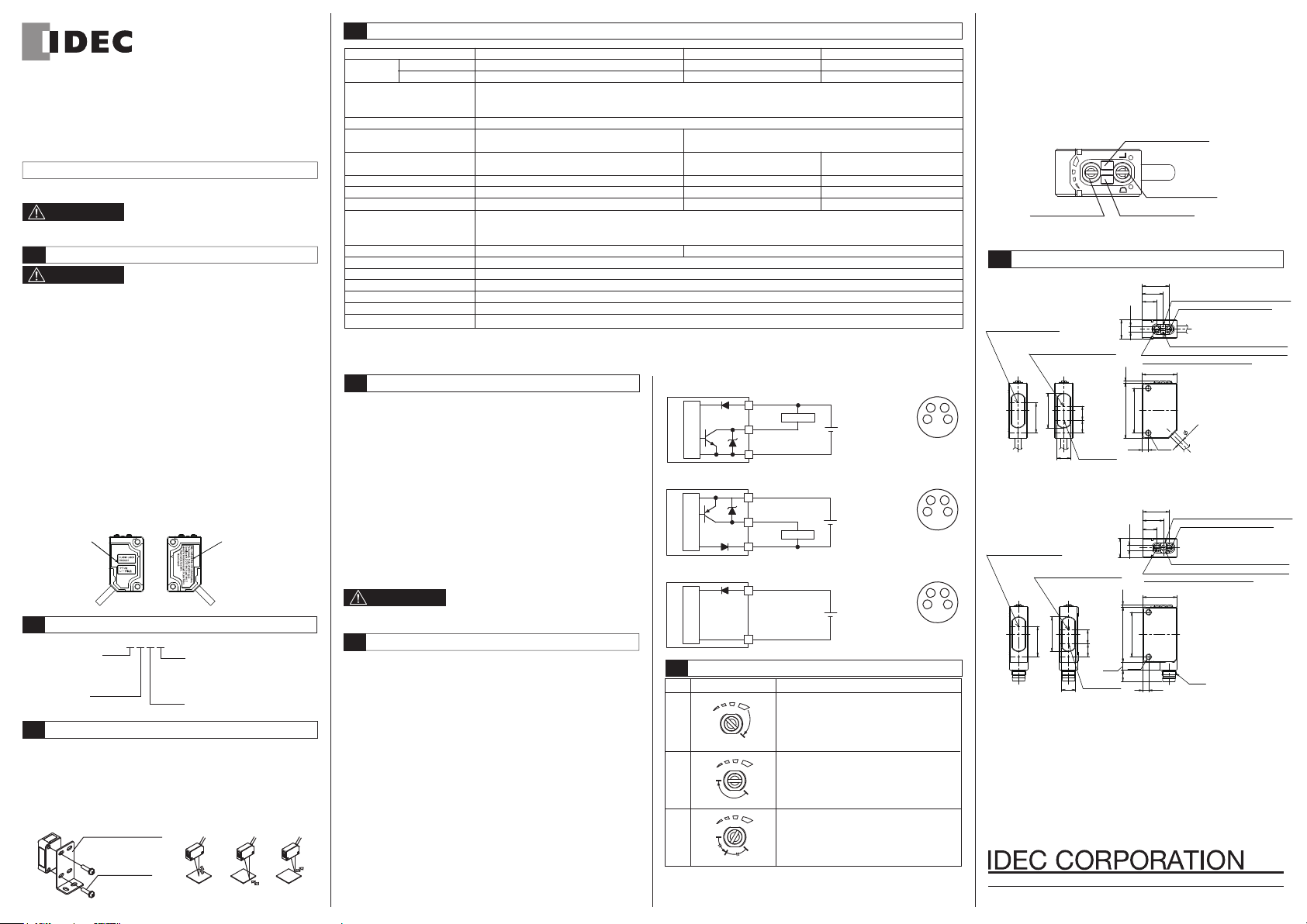
□WIRING DIAGRAM
NPN Output Type
Main circuit
PNP Output Type
Main circuit
Brown(1)
+V
Black(4)
OUT
Blue(3)
0V
Brown(1)
+V
Black(4)
OUT
Blue(3)
0V
Load
Load
12 to
24V DC
12 to
24V DC
1
Connector pin
assignment
1
Connector pin
assignment
Through-beam Type (Emitter)
Brown(1)
+V
Main circuit
Adjustment for Background suppression type
7
Step
Distance Control Adjusting Procedure
1
2
3
Blue(3)
0V
Install a photoelectric sensor and the sensing
object. Turn the control counter-clockwise until
the operation LED turns OFF (*1). Then turn
clockwise until the operation LED turns ON
A
(point A).
Remove the sensing object, then the operation
LED turns OFF. Turn clockwise until the
B
B
C
operation LED turns ON (The background is
detected) (point B). (*2)
A
Set the middle point between point A and B as
point C. (*3)
A
12 to
24V DC
1
Connector pin
assignment
*1: If the operation LED turned off, turn on by turning the control
clockwise.
*2: Make one turn or more clockwise from point A and set the position as
point C when the background is too far and the operation LED dose
turn ON.
*3: There may be more than 1 turn between points A and B, since this
photoelectric sensor incorporates a 6-turn adjuster.
Operation Indicator (Yellow)
(*4)
Sensing Range Control
6-turnendless
Operation Mode Switch
Stability Indicator (Green)
*4: Sensing range becomes longer when turned clockwise.
Dimensions
8
・ CABLE TYPE
Emitter axis(Emitter)
Receiver axis(Receiver)
432
Through-Beam
432
・ CONNECTOR TYPE
432
Through-Beam
Note1: Stability Indicator and Sensitivity Control and Operation Mode
Note2: Power Indicator (Green LED) is attached to the Emitter of
Receiver axis
(Polarized Retro-Reflective)
19.8
17.1
Emitter axis(Emitter)
Receiver axis(Receiver)
8.0
7.2
7.8
Emitter axis
Polarized Retro-Reflective
Background Suppression
Receiver axis
(Polarized Retro-Reflective)
19.8
17.1
8.0
7.2
Emitter axis
7.8
Polarized Retro-Reflective
Background Suppression
Switch are not attached to the Emitter of Through-Beam Type.
Through-Beam Type instead of Operation Indicator.
15.3
11.8
Operation Indicator (Yellow LED)(Note2)
8.2
3.2
10.8
1.2
31.5
3.4
3.2
10.8
31.5 1.2
25.4
2-M3
4.5
6.3
Operation Mode Switch (Note1)
Stability Indicator (Green LED)(Note1)
Sensitivity Control (except for BGS TYPE)(Note1)
Sensing Range Control (for BGS Type)
19.5
25.4
2-M3
15.3
Operation Indicator (Yellow LED)(Note2)
11.8
Operation Mode Switch (Note1)
8.2
Stability Indicator (Green LED)(Note1)
Sensitivity Control (except for BGS TYPE)(Note1)
Sensing Range Control (for BGS Type)
19.5
3.4
3.5
M8X1
http://www.idec.com
2012.3
 Loading...