

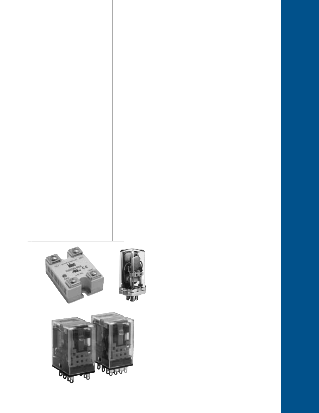
Relays
Section
E
Selection Guides..................................E-2
General Purpose Relays
• RU Series . . . . . . . . . . . . . . . . . . . . . E-3
• RR Series . . . . . . . . . . . . . . . . . . . . .E-6
• RH Series . . . . . . . . . . . . . . . . . . . . E-10
• RM Series . . . . . . . . . . . . . . . . . . . . E-16
• RY Series . . . . . . . . . . . . . . . . . . . .E-19
Latching Relays
• RR2KP Series . . . . . . . . . . . . . . . . . E-23
• RH2L Series . . . . . . . . . . . . . . . . . . E-26
• RY2KS Series . . . . . . . . . . . . . . . . . E-29
• RY2L Series . . . . . . . . . . . . . . . . . . E-32
Solid State Relays
• RSS Series. . . . . . . . . . . . . . . . . . . . E-35
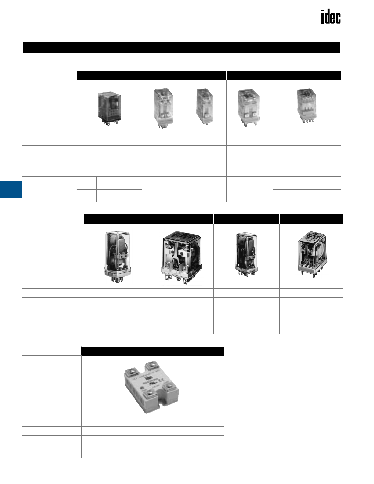
Relays
General Purpose Relays
Appearance
Page
Contact Configuration
Contact Rating
(resistive)
Contact Material
E
Selection Guides
RU Series
E-3 E-6 E-10 E-16 E-19
2, 4 Form C 1, 2, 3 Form C
DPDT: 10A, 30V DC
10A, 250V AC
4PDT: 6A, 30V DC
6A, 250V AC
DPDT
4PDT
AuSnOIn (silver tin
oxide indium)
AuAg/Ag (goldsilver alloy on silver)
RR Series RH Series RM Series RY Series
10A, 30V DC
10A, 120V, 240V AC
1/3HP, 240V AC
1/4HP, 120V AC
Silver
Selection Guide
1, 2, 3, 4 Form C 2 Form C 2, 4 Form C
10A, 30V DC
10A, 120V, 240V AC
1/3HP, 240V AC
1/6HP, 120V AC
Silver-cadmium
oxide
5A, 30V DC
5A, 120V AC, 240V AC
Silver
DPDT: 3A, 30V DC;
3A, 120V AC, 240V AC
4PDT: 5A, 30V DC;
5A, 120V AC, 240V AC
Standard Silver, gold-plated
Bifurcated
Silver-paladium
alloy (Ag-PD Alloy)
General Purpose Latching Relays
RR2KP Series
Appearance
Page
Contact Configuration
Contact Rating
(resistive)
Contact Material
2 Form C 2 Form C 2 Form C 2 Form C
10A, 30V DC
10A, 120V AC
Silver Silver-cadmium oxide Silver, gold-plated Silver, gold-flashed
Solid State Relays
Appearance
RH2L Series RY2KS Series RY2L Series
E-23 E-26 E-29 E-32
10A, 30V DC
7.5A, 240V AC
10A, 120V AC
3A, 30V DC
3A, 120V AC
3A, 30V DC
3A, 120V AC
3A, 240V AC
RSS Series
Page
Contact Configuration
Contact Rating
Output
E-2
E-35
1 Form A (SPST-NO)
10, 25, 50, 75, 90A
48V AC to 660V AC Output Ratings
Dual SCR (zero crossing)
www.idec.com
USA: (800) 262-IDEC or (408) 747-0550, Canada (888) 317-IDEC
Ordering Information
Basic Part No. Coil Voltage:
RU4S
A110
–
Relays
RU Series — General Purpose Relays
Key features of the RU series include:
• Non-polarized LED indicator
• Solder-free construction (lead-free)
• No internal wires
• Mechanical flag indicator
• Manual latching lever with color coding for AC or DC coil
• Snap-on marking plate
• Cadmium-free contacts
• Contact rating 6A: 4PDT
10A: DPDT
RU2 RU4
Contact Material
Contact Resistance
Minimum
Applicable Load
Operating Time
Release Time
Maximum
Continuous Applied
Voltage
(AC/DC) at 20°C
Minimum
Operating Voltage
(AC/DC) at 20°C
Drop-Out Voltage
(AC) at 20°C
Drop-Out Voltage
(DC) at 20°C
Power Consumption
Dielectric Strength
Specifications
Frequency Response
Vibration Resistance
Shock Resistance
Life Expectancy
Degreee of Protection
Operating Temperature
Weight
AuSnOIn (silver tin oxide
indium)
50 m
24VDC, 5mA (reference
20 msec maximum
20 msec maximum
1.1-1.4VA (AC); 0.9-1.0W (DC)
Between contact and coil:
2,500VAC, 1 minute
Between poles:
2,500VAC, 1 minute
Between contacts of the
same pole:
1,000VAC, 1 minute
1,800 operations/hr
Operating extremes:
Amplitude 1.0 mm p-p
Damage limits: 10 to 55Hz,
Amplitude 1.0 mm p-p
Operating extremes:
150 m/s2 (15G)
1,000 m/s2 (100G)
AC: 20,000,000 operations
DC: 30,000,000 operations
see electrical life curve
-55 to +70°C (no freezing)
AuAg/Ag (gold-silver alloy
on silver)
Ω
maximum
value)
110%
80%
30%
10%
Between contact and coil:
2,500VAC, 1 minute
Between poles:
2,000VAC, 1 minute
Between contacts of the
same pole:
1,000VAC, 1 minute
10 to 55Hz,
Damage limits:
Mechanical:
minimum
minimum
Electrical:
IP40
35g
RU Series
UL Recognized
File No. E66043
E
Order standard voltages for fastest delivery. Allow extra delivery time
for non-standard voltages.
www.idec.com
USA: (800) 262-IDEC or (408) 747-0550, Canada (888) 317-IDEC
E-3
Relays
Part Numbers: RU Series with Options
Termination Contact Configuration Basic Part No.
S: Solder/plugin
DPDT RU2S
4PDT RU4S
Part Numbers: Sockets
Relays
RU2 SM2S-05 SM2S-05C SY4S-51
RU4 SY4S-05 SY4S-05C SY4S-51
Standard DIN
Rail Mount
See Section F for details on sockets. All DIN rail mount
sockets shown above can be mounted using DIN rail BNDN1000.
Finger-Safe DIN
Rail Mount
E
Part Numbers
Panel Mount PC Mount
SY4S-61
SY4S-62
SY4S-61
SY4S-62
Ratings
RU Series
Springs & Clips (optional)
Part Number Use With
SY4S-02F1
SFA-101
SFA-202
SFA-301
SFA-302
SY4S-51F1
use with SY4S-05, -05C & SM2S-05, -05C
use with SY4S-51, -61
Coil Ratings
Rated Voltage
24V
AC
110-120V
220-240V
12V
DC
24V
110V
Contact Ratings
Voltage
30V DC
110V DC
120V AC
240V AC
DPDT 10A 5A
4PDT 6A 3A
DPDT 0.6A 0.3A
4PDT 0.4A 0.2A
DPDT 10A 5A
4PDT 6A 3A
DPDT 10A 5A
4PDT 6A 3A
Rated Current ±15% at 20°C
60Hz 50Hz Energizing De-Energizing
37.5mA – 164
8.4mA – 4,550
4.2mA – 18,230
83.3mA 160
41.7mA 605
9.1mA 12, 100
Coil Resistance ±10% at 20°C Inrush Current
Ω
Ω
Ω
Ω
Ω
Ω
60mA 1.8H 0.96H
14mA 36H 22H
7mA 144H 87H
Inductance
N/A
Resistive Inductive
E-4
www.idec.com
USA: (800) 262-IDEC or (408) 747-0550, Canada (888) 317-IDEC
Relays
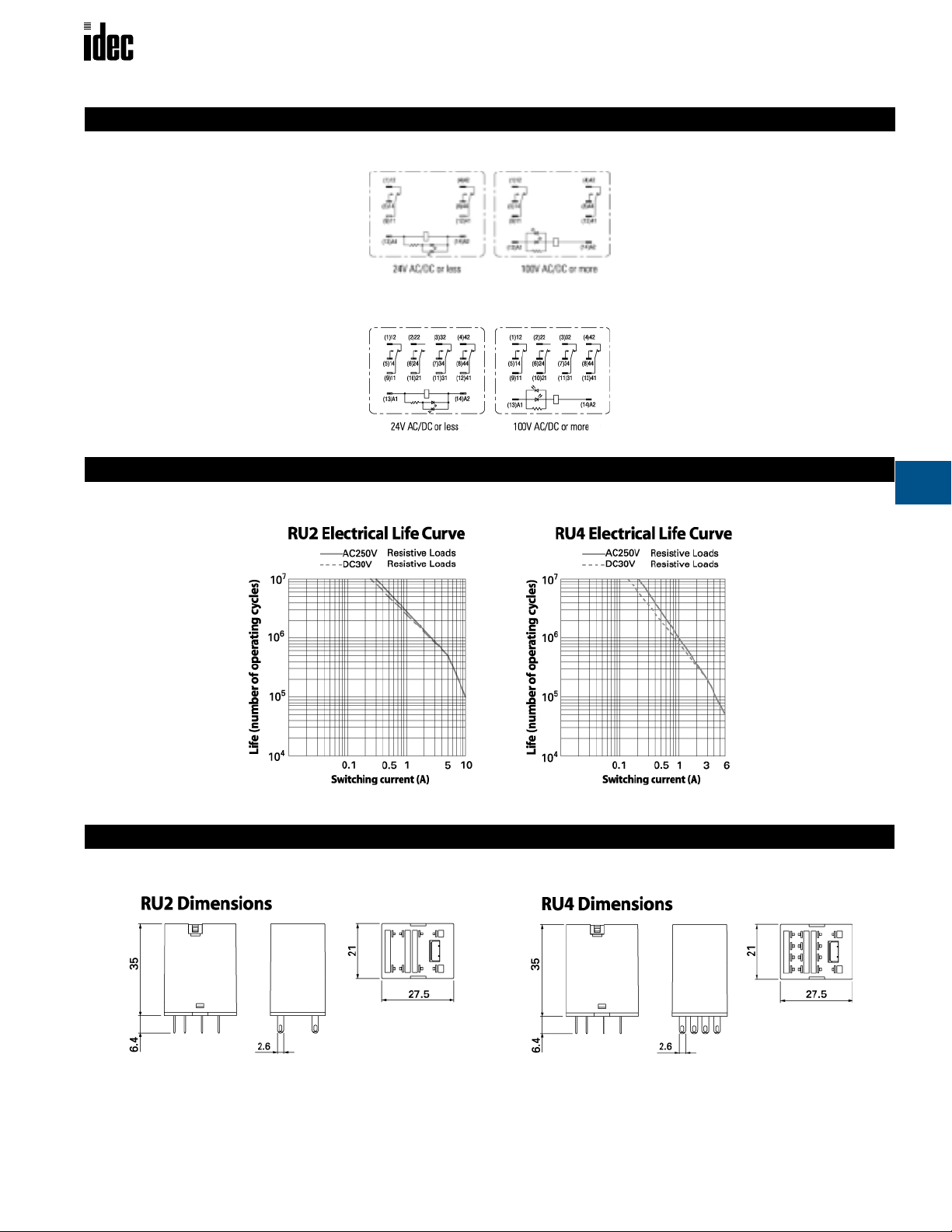
RU Series
Internal Circuit
RU2
RU4
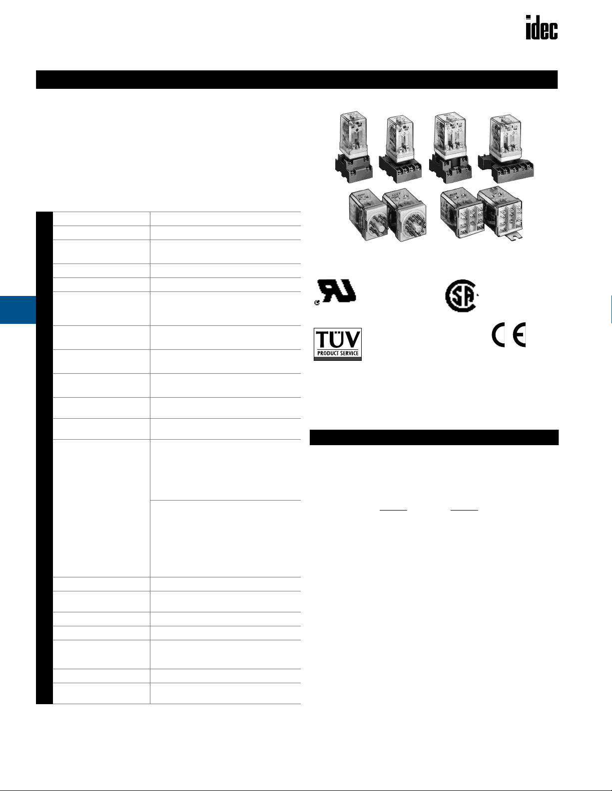
Electrical Life Curves
E
www.idec.com
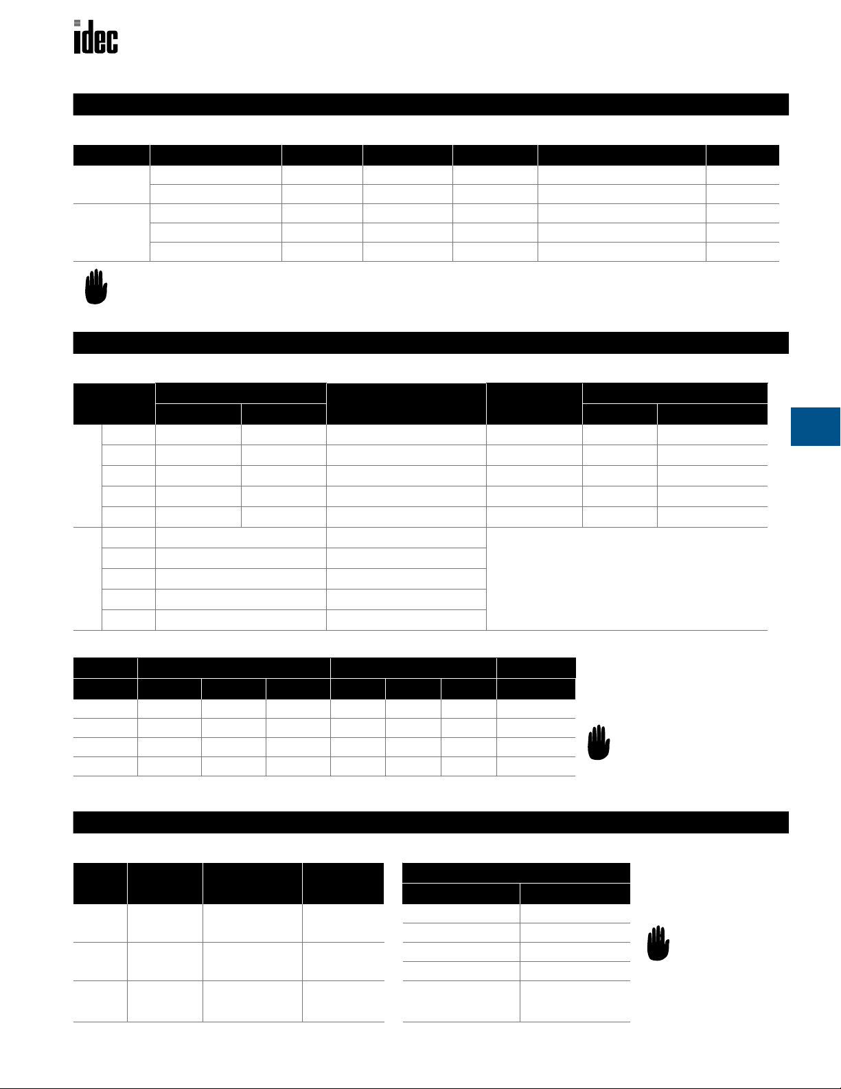
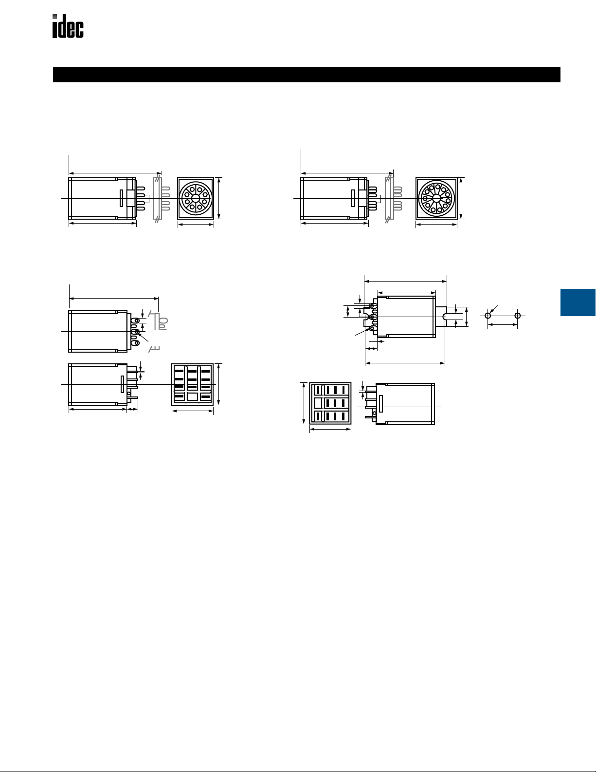
Dimensions
USA: (800) 262-IDEC or (408) 747-0550, Canada (888) 317-IDEC
E-5
Relays
RR Series — General Purpose Power Relays
Key features of the RR series include:
• High reliability and long service life
• Available in octal (8- and 11-pin) or square (11-blade) base
• Options include check button for test operation, indicator light, and
side flange
• DIN rail, surface and panel type sockets available for a wide range of
mounting applications
Silver
30m
Ω
maximum (initial value)
24V DC/10mA, 5V DC/20mA
(reference value)
25ms maximum
25ms maximum
110% of the rated voltage
80% of the rated voltage
30% of the rated voltage
15% of the rated voltage
AC: approximately 3VA (50Hz), 2.5VA (60Hz)
DC: approximately 1.5W
100M
Ω
minimum
(measured with 500V DC megger)
Pin (RR2P, RR3PA)
Between live and dead parts:
1,500V AC, 1 minute
Between contact circuit and operating coil:
1,500V AC, 1 minute
Between contact circuits: 1,500V AC,
1 minute (1,000V AC between NO-NC contacts)
Blade (RR1BA, RR2BA, RR3B)
Between live and dead parts:
2,000V AC, 1 minute
Between contact circuit and operating coil:
2,000V AC, 1 minute
Between contact circuits:
2,000V AC, 1 minute
Between contacts of same polarity:
1,000V AC, 1 minute
1,800 operations/hour
Coil: 85°C maximum
Contact: 65°C maximum
0 to 6G (55Hz maximum)
100N (approximately 10G)
Electrical: over 500,000 operations
(120V, 50/60Hz, 10A)
Mechanical: over 10,000,000 operations
–30 to +70°C
RR2P: 90g, RR3P/RR3PA: 96g (approximately)
RR1BA/RR2BA/RR3B: 82g (approximately)
E
Contact Material
Contact Resistance
Minimum
Applicable Load
Operating Time
Release Time
Maximum Continuous
Applied Voltage (AC/
DC) at 20°C
Minimum Operating
Voltage (AC/DC) at 20°C
Drop-Out Voltage
(AC) at 20°C
Drop-Out Voltage
(DC) at 20°C
Power Consumption
Insulation Resistance
Specifications
Dielectric Strength
Frequency Response
Temperature Rise
Vibration Resistance
Shock Resistance
Life Expectancy
Operating Temperature
Weight
RR Series
UL Recognized
File Nos. E67770
File No. BL951113332319*
* Pin Style Only
(does not apply to blade style)
Ordering Information
Order standard voltages for fastest delivery. Allow extra delivery time for
non-standard voltages.
Basic Part No. Coil Voltage:
RR3PA-U AC120V
–
CSA Certified
File No. LR35144
*
* Pin Style Only
E-6
www.idec.com
USA: (800) 262-IDEC or (408) 747-0550, Canada (888) 317-IDEC
Inductive load:
cos ø = 0.3, L/R = 7ms.
See Section F for
details on sockets.
All DIN rail mount
sockets listed can be
mounted using DIN
rail BNDN1000.
Relays
RR Series
Part Numbers
Part Numbers: RR Series with Options
Termination Contact Configuration Basic Part No. Indicator Light Check Button Light and Check Button Side Flange
P, PA
(pin)
B, BA
(blade)
1.RR1BA, RR2BA, and RR3PA are U.S. standard terminal arrangements.
2. For diode option on DC coils please consult factory.
DPDT RR2P-U RR2P-UL RR2P-UC RR2P-ULC —
3PDT RR3PA-U RR3PA-UL RR3PA-UC RR3PA-ULC —
SPDT RR1BA-U RR1BA-UL RR1BA-UC RR1BA-ULC RR1BA-US
DPDT RR2BA-U RR2BA-UL RR2BA-UC RR2BA-ULC RR2BA-US
3PDT RR3B-U RR3B-UL RR3B-UC RR3B-ULC RR3B-US
Ratings
Coil Ratings
Rated Voltage
6V
12V
24V
AC
120V
240V
6V
12V
24V
DC
48V
110V
Rated Current ±15% at 20°C
60Hz 50Hz Energizing De-Energizing
420mA 490mA 4.9
210mA 245mA 18
105mA 121mA 79
20.5mA 24mA 2100
10.5mA 12.1mA 8330
240mA 25
120mA 100Ω
60mA 400Ω
30mA 1600Ω
13mA 8460Ω
Coil Resistance ±10% at 20°C Inrush Current
Ω
Ω
Ω
Ω
Ω
Ω
720mA 0.04H 0.02H
365mA 0.15H 0.08H
182mA 0.57H 0.32H
35mA 15H 8.2H
18mA 57H 32H
Inductance
N/A
E
Contact Ratings
Voltage Nominal UL CSA Nominal UL CSA UL
30V DC 10A 10A 10A 7.5A 7A 7.5A —
110V DC 0.5A — — 0.3A — 0.5A —
120V AC 10A 10A 10A 7.5A 7.5A 7.5A 1/4 hp
240V AC 7.5A 10A 10A 5A 7A 7A 1/3 hp
Part Numbers: Sockets
Relays
RR2P
RR3PA
RR1BA
RR2BA
RR3B
www.idec.com
Standard DIN
Rail Mount
SR2P-05
SR2P-06
SR3P-05
SR3P-06
SR3B-05 — SR3B-51 SR3B-02F1
Resistive Inductive Motor Load
Applicable Sockets
Finger-Safe DIN
Rail Mount
SR2P-05C SR2P-51
SR3P-05C SR3P-51
Panel Mount
Springs & Clips (optional)
Part Numbers Use With
SR2B-02F1 SR2P-05, -05C, -06
SR3P-01F1 SR2P-51
SR3B-02F1 SR3P-05, -05C, -06
SR3P-01F1 SR3P-51
SR3B-05
SR3B-51
USA: (800) 262-IDEC or (408) 747-0550, Canada (888) 317-IDEC
E-7
Relays RR Series
012345678910
10
50
100
500
1000
DC 30V Resistive
DC 100V Inductive
DC 100V Resistive
DC 30V Inductive
Load Current (A)
Life (x 10,000) Operations
Internal Circuit
E
1000
500
3
2
2
5
7
(-)
RR1BA
AC 110V Resistive
AC 220V Resistive
AC 110V Inductive
AC 220V Inductive
BA
(+)
4
1
RR2P
5
6
7
(+)(-)
8
1
4
7
(-)
3
6
9
BA
(+)
RR2BA
Electrical Life Curves
6
57
3
2
1
RR3PA
1
4
7
(-)
11
84
9
10
2
5
8
RR3B
(+)(-)
3
6
9
BA
(+)
Life (x 10,000) Operations
100
50
10
012345678910
Load Current (A)
E-8 www.idec.com USA: (800) 262-IDEC or (408) 747-0550, Canada (888) 317-IDEC
Relays RR Series
Dimensions
8-Pin
RR2P
Total length from panel surface including socket:
SR2P-05: 3.33" (85.3mm) [3.44" (88.3mm) maximum]
SR2P-51: 2.48" (63.6mm) [2.68" (68.7mm) maximum]
2.18" (56mm) or Less
1.14" (29.3mm)
1.42" (36.4mm)
Blade
RR1BA, RR2BA, RR3B
Total length from panel surface including socket:
SR3B-02: 2.87"
SR3B-51: 2.21" (56.6mm) [2.36" (60.6mm) maximum]
1.87" (48mm) or less
(73.7mm) [3.0" (76.7mm) maximum]
0.187" (4.8mm)
0.078" (2mm) x 0.117" (3mm)
Terminal Hole
0.02"
(0.51mm)
0.288"
(7.4mm)
1.42" (36.4mm)
1.42" (36.4mm)
Note: Dimensions in [ ] include hold-down spring.
11-Pin
RR3PA
Total length from panel surface including socket:
SR2P-05: 3.33" (85.3mm) [3.44" (88.3mm) maximum]
SR2P-51: 2.48" (63.6mm) [2.68" (68.7mm) maximum]
2.18" (56mm) or Less
1.42" (36.4mm)
Side Flange
RR1BA-US, RR2BA-US, RR3B-US
2.94" (75.4mm)
1.09" (28mm) or less
0.288" (7.4mm)
0.644" (16.5mm)
2.54" (65mm)
0.02" (0.51mm)
0.444"
(11.4mm)
Ø 0.117"
3 T erminal Holes
1.44" (37mm)
1.44" (37mm)
0.187"
(4.8mm)
(3mm)
1.42" (36.4mm)
0.168"
(4.3mm)
0.64" (16.4mm)
Ø 0.18" (4.6mm)
2 Mounting Holes
2.54" (65mm)
E
www.idec.com
USA: (800) 262-IDEC or (408) 747-0550, Canada (888) 317-IDEC
E-9
Relays RH Series
RH2B-U AC110-120V
Basic Part No. Coil Voltage:
–
RH Series — General Purpose Midget Relays
Key features of the RH series include:
• Compact midget size saves space
• High switching capacity (10A)
• Choice of blade or PCB style terminals
• Relay options include indicator light, check button, and top
mounting bracket
• DIN rail, surface, panel, and PCB type sockets
available for a wide range of mounting applications
Silver cadmium oxide
50mΩ maximum (initial value)
24V DC/30mA, 5V DC/100mA
(reference value)
SPDT (RH1), DPDT (RH2): 20ms maximum
3PDT (RH3), 4PDT (RH4): 25ms maximum
SPDT (RH1), DPDT (RH2): 20ms maximum
3PDT (RH3), 4PDT (RH4): 25ms maximum
110% of the rated voltage
80% of the rated voltage
30% or more of the rated voltage
10% or more of the rated voltage
SPDT (RH1): DC: 0.8W
AC: 1.1VA (50Hz), 1VA (60Hz)
DPDT (RH2): DC: 0.9W
AC: 1.4VA (50Hz), 1.2VA (60Hz)
3PDT (RH3): DC: 1.5W
AC: 2VA (50Hz), 1.7VA (60Hz)
4PDT (RH4): DC: 1.5W
AC: 2.5VA (50Hz), 2VA (60Hz)
100MΩ min (measured with a 500V DC megger)
SPDT (RH1)
Between live and dead parts: 2,000V AC, 1
minute; Between contact circuit and operating coil: 2,000V AC, 1 minute;
Between contacts of the same pole: 1,000V
AC, 1 minute
DPDT (RH2), 3PDT (RH3), 4PDT (RH4)
Between live and dead parts: 2,000V AC, 1
minute; Between contact circuit and operating coil: 2,000V AC, 1 minute;
Between contact circuits: 2,000V AC,
1 minute; Between contacts of the same
pole: 1,000V AC, 1 minute
1,800 operations/hour
Coil: 85°C maximum
Contact: 65°C maximum
0 to 6G (55Hz maximum)
SPDT/DPDT: 200N (approximately 20G)
3PDT/4PDT: 100N (approximately 10G)
Electrical: over 500,000 operations at 120V
AC, 10A; (over 200,000 operations at 120V
AC, 10A for SPDT [RH1], 3PDT [RH3], 4PDT
[RH4])
Mechanical: 50,000,000 operations
–30 to +70°C
SPDT: 24g, DPDT: 37g (approximately)
3PDT: 50g, 4PDT: 74g (approximately)
UL Recognized
Files No. E67770
E59804
File No. BL951113332319
Ordering Information
Order standard voltages for fastest delivery. Allow extra delivery time for
non-standard voltages.
E
Contact Material
Contact Resistance
Minimum Applicable
Load
Operating Time
Release Time
Maximum Continuous
Applied Voltage
(AC/DC) at 20°C
Minimum Operating
Voltage (AC/DC) at 20°C
Drop-Out Voltage (AC)
Drop-Out Voltage (DC)
Power
Consumption
Insulation Resistance
Specifications
Dielectric Strength
Frequency Response
Temperature Rise
Vibration Resistance
Shock Resistance
Life Expectancy
Operating Temperature
Weight
CSA Certified
File No.LR35144
E-10 www.idec.com USA: (800) 262-IDEC or (408) 747-0550, Canada (888) 317-IDEC
Relays RH Series
Part Numbers
Part Numbers: RH Series with Options
Termination Contact Configuration Basic Part No. Indicator Light Check Button Indicator Light and Check Button Top Bracket
SPDT RH1B-U RH1B-L* — — RH1B-UT
B
(blade)
V2
(PCB 0.078"
[2mm] wide)
* RH1B(V2)-L is not UL recognized.
DPDT RH2B-U RH2B-UL RH2B-UC RH2B-ULC RH2B-UT
3PDT RH3B-U RH3B-UL RH3B-UC RH3B-ULC RH3B-UT
4PDT RH4B-U RH4B-UL RH4B-UC RH4B-ULC RH4B-UT
SPDT RH1V2-U RH1V2-L* — — —
DPDT RH2V2-U RH2V2-UL RH2V2-UC RH2V2-ULC —
3PDT RH3V2-U RH3V2-UL RH3V2-UC RH3V2-ULC —
4PDT RH4V2-U RH4V2-UL RH4V2-UC RH4V2-ULC —
Ratings
Coil Ratings
Rated Voltage
60Hz 50Hz
SPDT DPDT 3PDT 4PDT SPDT
6V 150mA 200mA 280mA 330mA 170mA 238mA 330mA 387mA 18.8Ω 9.4Ω 6.0Ω 5.4Ω
12V 75mA 100mA 140mA 165mA 86mA 118mA 165mA 196mA 76.8Ω 39.3Ω 25.3Ω 21.2Ω
24V 37mA 50mA 70mA 83mA 42mA 59.7mA 81mA 98mA 300Ω 153Ω 103Ω 84.5Ω
AC
120V* 7.5mA 11mA 14.2mA 16.5mA 8.6mA 12.9mA 16.4mA 19.5mA 7,680Ω 4,170Ω 2770Ω 2220Ω
240V† 3.2mA 5.5mA 7.1mA 8.3mA 3.7mA 6.5mA 8.2mA 9.8mA 3,1200Ω 15,210Ω 12,100Ω 9120Ω
Rated Current ±15% at 20°C
DPDT
3PDT
4PDT
Coil Resistance ±15% at 20°C
SPDT DPDT 3PDT 4PDT
SPDT DPDT 3PDT 4PDT SPDT DPDT 3PDT 4PDT
6V 128mA 150mA 240mA 250mA 47Ω 40Ω 25Ω 24Ω
12V 64mA 75mA 120mA 125mA 188Ω 160Ω 100Ω 96Ω
24V 32mA 36.9mA 60mA 62mA 750Ω 650Ω 400Ω 388Ω
DC
48V 18mA 18.5mA 30mA 31mA 2,660Ω 2,600Ω 1,600Ω 1550Ω
110V‡ 8mA 9.1mA 12.8mA 15mA 13,800Ω 12,100Ω 8,600Ω 7,340Ω
* For RH2 relays = 110/120V AC.
† For RH2 relays = 220/240V AC.
‡ For RH2 relays = 100/110V DC.
Rated Voltage
SPDT DPDT 3PDT 4PDT SPDT
6V 250mA 340mA 520mA 620mA 0.09H 0.08H 0.05H 0.05H 0.06H 0.04H 0.03H 0.02H
12V 120mA 170mA 260mA 310mA 0.037H 0.30H 0.22H 0.18H 0.22H 0.16H 0.12H 0.10H
24V 56mA 85mA 130mA 165mA 1.5H 1.2H 0.9H 0.73H 0.9H 0.63H 0.5H 0.36H
AC
120V* 12mA 16mA 26mA 33mA 37H 33H 21H 18H 22H 15H 12H 9H
240V† 7mA 8mA 12mA 16mA 130H 130H 84H 73H 77H 62H 47H 36H
Coil Inrush
Energizing De-Energizing
DPDT
3PDT
Coil Inductance
4PDT
SPDT DPDT 3PDT 4PDT
SPDT DPDT 3PDT 4PDT SPDT DPDT 3PDT 4PDT
6V
12V
24V
DC
48V
110V‡
* For RH2 relays = 110/120V AC.
† For RH2 relays = 220/240V AC.
‡ For RH2 relays = 100/110V DC.
N/A N/A N/A N/A N/A N/A N/A N/A
E
www.idec.com
USA: (800) 262-IDEC or (408) 747-0550, Canada (888) 317-IDEC
E-11
Relays RH Series
Ratings con’t
Contact Ratings
Voltage Rating
28V DC
UL 10A 10A 10A 10A 7.5A — — 7.5A — — —
SPDT DPDT 3PDT 4PDT SPDT DPDT 3PDT 4PDT SPDT DPDT 3PDT
UL
30V DC
CSA
10A 10A 10A
Nominal 7.5A 7.5A — — —
110V DC
Nominal 0.5A 0.5A 0.5A 0.5A 0.3A 0.3A 0.3A 0.3A — — —
UL
120V AC
CSA
10A 10A 10A 10A
Nominal 7A 7.5A
240V AC
UL
CSA 7A
10A 10A — 7.5A 7A 7A
Nominal 7A 7.5A 7.5A 4.5A 5A 5A 5A
1.* 6.5A/pole, 20A total.
2.Inductive load cos ø = 0.3, L/R = 7ms.
Resistive Inductive Motor Load
—
10A 7.5A
7A
7.5A
7A
—
——
—
7.5A — — —
*
———
———
1/6 1/6 1/6
7.5A
1/3 1/3 1/3
5A
———
E
Part Numbers: Sockets
Relay
RH1B
RH2B
RH3B
RH4B
Standard DIN
Rail Mount
SH1B-05 SH1B-05C
SH2B-05 SH2B-05C SH2B-02 SH2B-51 SH2B-62
SH3B-05 SH3B-05C
SH4B-05 SH4B-05C SH4B-51 SH4B-62
See Section F for details on sockets. All DIN rail mount sock ets shown above can be mounted using
DIN rail BNDN1000.
Finger-Safe DIN
Rail Mount
Surface Mount
—
—
Applicable Sockets
Panel
Mount
SH1B-51 SH1B-62
SH3B-51 SH3B-62
PCB Mount
Spring & Clips (optional)
Part Number Use With
SY2S-02F1
SFA-101
SFA-202
SY4S-51F1
SFA-301
SFA-302
SY4S-02F1
SFA-101
SFA-202
SY4S-51F1
SFA-301
SFA-302
SH3B-05F1
SFA-101, -202
SY4S-51F1
SFA-301
SFA-302
SH4B-02F1
SFA-101, -202
SY4S-51F1
SFA-301
SFA-302
SH1B-05, 05C
SH1B-51, 62
SH2B-05, 05C
SH2B-51, 62
SH3B-05, 05C
SH3B-51, 62
SH4B-05, 05C
SH4B-51, 62
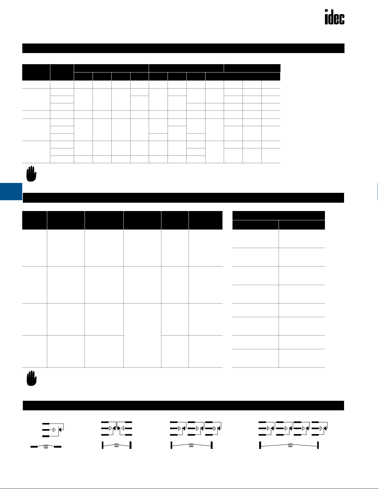
Internal Circuits
1
5
9
(-) (+)
RH1
1
5
9
1413
(-)
RH2
4
8
12
1413
(+)
1
2
4
65
8
9
10
12
1413
(-)
(+)
RH3
1
2
3
65
9
10
(-)
4
7
8
11
12
1413
(+)
RH4
E-12 www.idec.com USA: (800) 262-IDEC or (408) 747-0550, Canada (888) 317-IDEC

RH1
Relays RH Series
Electrical Life Curves
1000
500
100
Life (x 10,000) Operations
50
20
AC 220V Inductive AC 220V ResistiveAC 110V Inductive
10
13579246810
RH2
1000
500
100
AC 110V Resistive
Load Current (A)
AC 110V Resistive
1000
500
100
DC 100V Resistive
50
Life (x 10,000) Operations
DC 30V Inductive
20
DC 100V Inductive
10
13579246810
1000
500
100
DC 30V Resistive
AC 220V Resistive
Load Current (A)
DC 30V Resistive
E
50
Life (x 10,000) Operations
20
10
13579246810
RH3 and 4
1000
500
100
50
Life (x 10,000) Operations
20
10
13579246810
AC 220V Inductive
AC 110V Resistive
Load Current (A)
AC 220V Inductive
Load Current (A)
AC 220V Resistive
AC 110V Inductive
AC 220V Resistive
AC 110V Inductive
50
Life (x 10,000) Operations
20
10
1000
500
100
50
Life (x 10,000) Operations
20
10
DC 100V Resistive
DC 100V Inductive
13579246810
DC 30V Resistive
DC 30V Inductive
DC 100V Resistive
DC 100V Inductive
13579246810
DC 30V
Inductive
Load Current (A)
Load Current (A)
www.idec.com
USA: (800) 262-IDEC or (408) 747-0550, Canada (888) 317-IDEC
E-13

Relays RH Series
Dimensions
E
Top Bracket Mounting
Blade Terminal
RH1B-UT
1.48" (38mm)
1.68" (43.2mm)
0.137"
(3.5mm)
0.566"
(14.5mm)
Plug-in
Blade Terminal
RH1B
Total length from panel surface including socket:
SH1B-05: 2.40" (61.5mm) maximum; SH1B-51: 1.54" (39mm) maximum
Total length from panel surface including hold-down spring:
SH1B-05: 2.48" (63.5mm) maximum; SH1B-51: 1.62" (41.6mm) maximum
1.39" (35.6mm)
or less
0.019"
(0.5mm)
0.078"
(2mm)
1.39" (35.6mm)
or Less
0.183"
(4.7mm)
Ø 0.101" (2.6mm)
0.019"
(0.5mm)
0.211"
(5.4mm)
0.25"
(6.4mm)
0.183"
(4.7mm)
Ø 0.101" (2.6mm)
0.185"
(4.7mm)
0.23"
(5.9mm)
0.257"
(6.6mm)
0.211"
(5.4mm)
0.25"
(6.4mm)
1.07" (27.5mm)
0.546"
(14mm)
1.07" (27.5mm)
0.019"
(0.5mm)
0.39"
(10mm)
Ø 0.101" (2.6mm)
0.183"
(4.7mm)
0.25"
(6.4mm)
RH2B-UT
1.48" (38mm)
1.68" (43.2mm)
0.137"
(3.5mm)
0.839"
(21.5mm)
0.078"
(2mm)
1.39" (35.6mm)
or Less
RH2B
Total length from panel surface including socket:
SH2B-05: 2.40" (61.5mm) maximum; SH2B-51: 1.54" (39.6mm)
Total length from panel surface including hold-down spring:
SH2B-05: 2.48" (63.5mm) maximum; SH2B-51: 1.62" (41.6mm)
Ø 0.101" (2.6mm)
0.019"
(0.5mm)
0.183"
1.39" (35.6mm)
or less
0.25"
(6.4mm)
(4.7mm)
1.07" (27.5mm)
0.819" (21mm)
0.185"
(4.7mm)
0.23"
(5.9mm)
0.293"
(7.5mm)
1.07" (27.5mm)
Plug-in
Blade Terminal
RH3B
Total length from panel surface including socket:
SH3B-05: 2.57" (66mm) maximum
Total length from panel surface including hold-down spring:
SH3B-05: 2.65" (68mm) maximum
0.019" (0.5mm)
1.39" (35.6mm) or Less
0.183"
(4.7mm)
Ø 0.101" (2.6mm)
0.25"
(6.4mm)
1.07" (27.5mm)
1.21" (31mm)
RH4B
Total length from panel surface including socket:
SH4B-05: 2.40" (61.5mm) or less; SH4B-51: 1.54" (39.6mm)
Total length from panel surface including hold-down spring:
SH4B-05: 2.48" (63.5mm) or less; SH4B-51: 1.62" (41.6mm)
0.183"
(4.7mm)
0.019" (0.5mm)
1.39" (35.6mm) or less
Ø 0.101" (2.6mm)
0.25"
(6.4mm)
1.07" (27.5mm)
1.60" (41mm)
E-14 www.idec.com USA: (800) 262-IDEC or (408) 747-0550, Canada (888) 317-IDEC

Relays RH Series
Dimensions
PCB Terminal
RH1V2
0.019" (0.5mm)
1.39" (35.6mm) or Less
RH3V2
0.019" (0.5mm)
(0.5mm)
1.39" (35.6mm)
or Less
0.059" (1.5mm)
0.019" (0.5mm)
0.019"
0.078"
(2mm)
0.179"
(4.6mm)
0.078"
(2mm)
1.07" (27.5mm)
0.179"
(4.6mm)
1.07" (27.5mm)
0.546" (14mm)
Ø 0.094"
(2.4mm) 11 Holes
1.21" (31mm)
Ø 0.094"
(2.4mm) 3 Holes
0.279" (7.15mm)
0.172"
(4.4mm)
0.39” (10mm)
0.39” (10mm)
0.304" (7.8mm)
0.183" (4.7mm)
0.488"
(12.5mm)
0.257" (6.6mm)
Ø 0.078"
(2mm) 2 Holes
0.183"
(4.7mm)
0.513"
(13.15mm)
0.283"
(7.25mm)
RH2V2
0.019" (0.5mm)
0.019" (0.5mm)
0.019" (0.5mm)
1.39" (35.6mm) or Less
RH4V2
0.019" (0.5mm)
0.019"
(0.5mm)
1.39" (35.6mm)
or Less
0.078"
(2mm)
0.195"
0.304"
(5mm)
(7.8mm)
0.179"
(4.6mm)
0.078"
(2mm)
1.07" (27.5mm)
1.60" (41mm)
0.179"
(4.6mm)
Ø 0.094"
(2.4mm) 8 Holes
0.39"
(10mm)
0.566" (14.5mm)
Ø 0.078"
(2mm) 14 Holes
0.183"
(4.7mm)
0.513"
(13.15mm)
0.283"
(7.25mm)
1.17" (30mm)
0.39" (10mm)
0.304" (7.8mm)
0.183"
(4.7mm)
0.513"
(13.15mm)
0.283"
(7.25mm)
E
RH3B-UT
1.40" (35.4mm)
1.50" (38.0mm)
1.24" (31.5mm)
1.73" (44.0mm)
RH4B-UT
1.40" (35.4mm)
1.50" (38.0mm)
1.63"(41.4mm)
1.73" (44.0mm)
1.10" (27.9mm)
www.idec.com
USA: (800) 262-IDEC or (408) 747-0550, Canada (888) 317-IDEC
E-15

Relays RM Series
RM Series — General Purpose Miniature Relays
Key features of the RM series include:
• Compact miniature size saves space
• High reliability and long service life
• Choice of plug-in/solder or PCB type terminals
• Options include models with indicator light, check button, and top
mount bracket
• DIN rail, surface, panel, and PCB type sockets available for a wide
range of mounting applications
E
Contact Material
Contact Resistance
Minimum
Applicable Load
Operating Time
Release Time
Maximum Continuous Applied Voltage
(AC/DC) at 20°C
Minimum Operating
Voltage
(AC/DC) at 20°C
Drop-Out Voltage
(AC)
Drop-Out Voltage
(DC)
Power Consumption
Insulation
Resistance
Specifications
Dielectric Strength
Frequency Response
Temperature Rise
Vibration Resistance
Shock Resistance
Life Expectancy
Operating
Temperature
Weight
Silver
30mΩ maximum (initial value)
24V DC/10mA, 5V DC/20mA
(reference value)
20ms maximum
20ms maximum
110% of the rated voltage
80% of the rated voltage
30% or more of the rated voltage
10% or more of the rated voltage
AC: Approximately 1.2VA (60Hz); 1.4VA (50Hz)
DC: Approximately 0.9W
100MΩ minimum
(measured with 500V DC megger)
Between live and dead parts:
2,000V AC, 1 minute
Between contact circuit and operating coil:
2,000V AC, 1 minute
Between contact circuits: 2,000V AC,
1 minute (1,000V between NO-NC contacts)
1,800 operations/hour
Coil: 85°C maximum
Contact: 65°C maximum
0 to 6G (55Hz maximum)
200N (approximately 20G)
Electrical: over 500,000 operations (240V AC, 5A)
Mechanical: over 50,000,000 operations
–30 to +70°C
35g (approximately)
UL Recognized
Files No. E59804
CSA Certified
File No.LR35144
File No. BL951113332319
Ordering Information
Order standard voltages for fastest delivery. Allow extra delivery time for
non-standard voltages.
Basic Part No. Coil Voltage:
RM2S-U AC110-120V
–
E-16 www.idec.com USA: (800) 262-IDEC or (408) 747-0550, Canada (888) 317-IDEC

Relays RM Series
Part Numbers
Part Numbers: RM Series with Options
Termination Contact Configuration Part No. Indicator Light Check Button Indicator Light and Check Button Top Bracket
S: Solder/
plug-in
V: PCB. 0.031"
(0.8mm) wide
Coil Ratings
Rated Voltage (V) 60Hz 50Hz Coil Resistance ±10% at 20°C
AC
DC
DPDT RM2S-U RM2S-UL RM2S-UC RM2S-ULC RM2S-UT
DPDT RM2V-U RM2V-UL RM2V-UC RM2V-ULC —
Ratings
Rated Current ±15% at 20°C
6 200mA 240mA 9.4Ω
12 100mA 121mA 39.3Ω
24 50mA 60.5mA 153Ω
120* 11mA 13.1mA 4170Ω
240 † 5.5mA 6.6mA 15210Ω
6 150mA 40Ω
12 75mA 160Ω
24 36.9mA 650Ω
48 18.5mA 2600Ω
110‡ 9.1mA 12100Ω
E
* For RM2 relays = 110/120V AC.
† For RM2 relays = 220/240V AC.
‡ For RM2 relays = 100/110V DC.
Contact Ratings
Resistive Inductive
Voltage Nominal UL CSA Nominal UL CSA
30V DC 5A 5A 5A 2.5A — 2.5A
110V DC 0.4A 0.4A — 0.4A — 0.4A
120V AC 5A 5A 5A 2.5A 2.5A 2.5A
240V AC 5A 5A 5A 2A 2A 2A
Applicable Sockets
Part Numbers: Sockets
Relay Standard DIN Rail Mount Finger-Safe DIN Rail Mount Panel Mount PC Mount Spring (optional)
SY4S-51F1
RM2S
SM25-05
SY4S-05
See Section F for details on sockets. All DIN rail mount sock ets shown above
can be mounted using DIN rail BNDN1000.
SM25-05C
SY4S-05C
SY4S-51
SY4S-61
SY4S-62
SFA-101
SFA-202
SFA-302
SFA-301
www.idec.com
USA: (800) 262-IDEC or (408) 747-0550, Canada (888) 317-IDEC
E-17

Relays RM Series
103524
50
100
500
1000
10
DC 30V Resistive
DC 30V Inductive
DC 100V Resistive
DC 100V Inductive
Load Current (A)
Life (x 10,000) Operations
Internal Circuit
E
AC 100V Resistive
AC 220V Resistive
1000
500
100
50
Life (x 10,000) Operations
10
103524
Load Current (A)
AC 110V Inductive
AC 220V Inductive
1
4
85
9
13
(-)
12
14
(+)
RM2
Electrical Life Curves
Solder Terminal
Plug-in
RM2S
Total length from panel surface including socket:
SH2S-02: 2.40" (61.6mm) maximum; SH2S-51: 1.56" (40mm)
Total length from panel surface including hold-down spring:
SH2S-02: 2.48" (63.6mm) maximum; SH2S-51: 1.64" (42mm)
0.019" (0.5mm)
1.40" (36mm) or Less
0.103" (2.64mm)
Ø 0.119" x 0.047"
(3.05 x 1.2mm)
0.214"
(5.5mm)
1.07" (27.5mm)
PCB Terminal
RM2S, RM2V
Hole
0.827" (21.2mm)
(5mm) 2 Holes
0.764" (19.6mm)
0.133"
(3.4mm)
0.52"
(13.3mm)
Ø 0.195"
RM2V: 0.032" (0.8mm)
0.019" (0.5mm)
Dimensions
0.646"
(16.6mm)
0.148"
(3.8mm)
0.103"
(2.64mm)
With Top Bracket
RM2S-UT
1.50" (38.4mm)
1.70" (43.6mm)
0.137"
0.846" (21.7mm)
RM2V: Ø 0.039" (1mm) 8 Holes
(3.5mm)
0.019" (0.5mm)
0.078"
(2mm)
1.40" (36mm) or Less
0.161"
(4.13mm)
0.50"
(12.8mm)
(5.5mm)
(2.64mm)
0.103"
0.519" (13.3mm)
Ø 0.119" x 0.047"
(3.05 x 1.2mm)
0.162"
(4.15mm)
0.25
(6.4mm)
0.254"
(6.5mm)
0.214"
Hole
1.07" (27.5mm)
E-18 www.idec.com USA: (800) 262-IDEC or (408) 747-0550, Canada (888) 317-IDEC
1.40" (36mm)
or Less
RM2V: 0.137" (3.5mm)
1.07" (27.5mm)
0.827" (21.2mm)
0.281" (7.2mm)
0.519"
(13.3mm)
0.254"
(6.5mm)

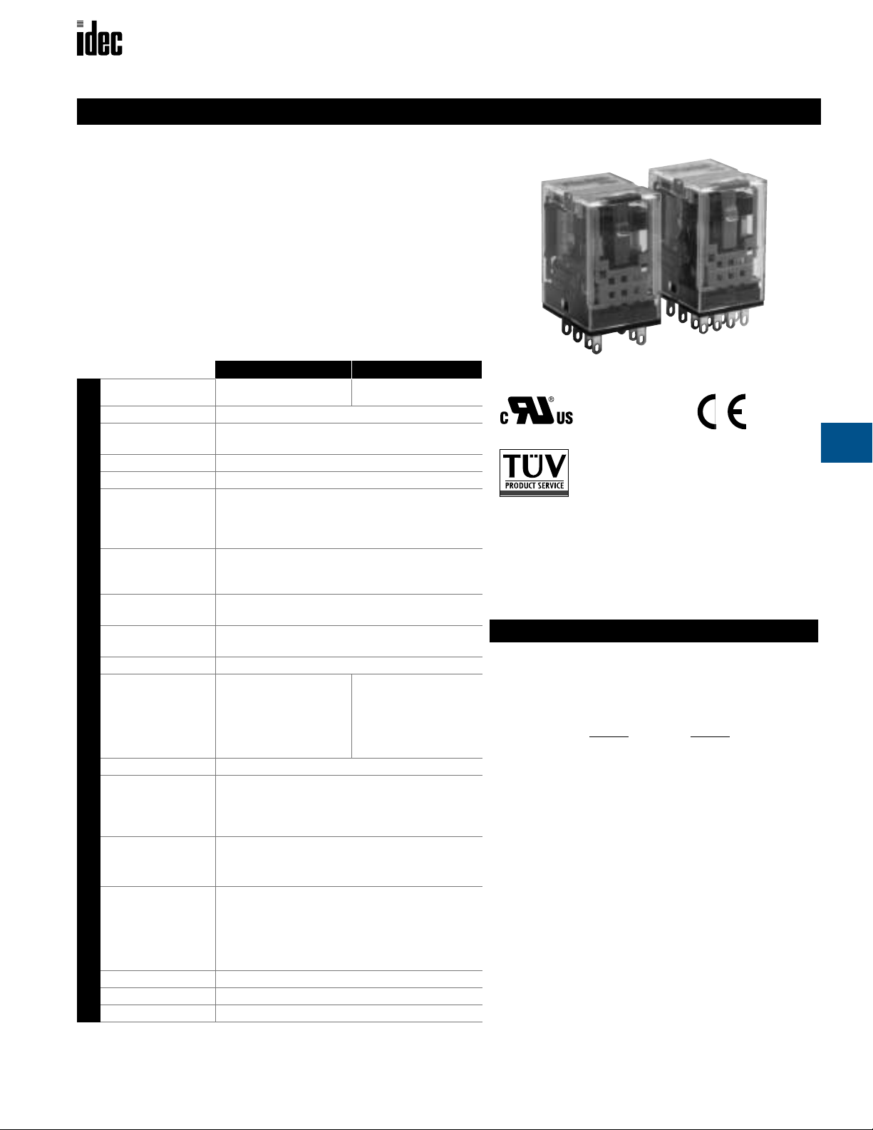
Relays RY Series
RY4S-U
AC110-120V
Basic Part No.
Coil V oltage:
–
RY Series — General Purpose Miniature Relays
Key features of the RY series include:
• Compact miniature size saves space
• 2PDT and 4PDT models, available with bifurcated crossbar contacts,
ensure reliable low-current switching for dry circuit applications
• Choice of plug-in/solder or PCB type terminals
• Options include check button for test operation and indicator lights
on 4PDT models
• DIN rail, surface, panel, and PCB type sockets available for a wide
range of mounting applications
Contact Material
Contact Resistance
Minimum
Applicable Load
Operating Time
Release Time
Maximum Continuous
Applied Voltage (AC/DC) at
20°C
Minimum Operating Voltage
(AC/DC) at 20°C
Drop-Out Voltage (AC)
Drop-Out Voltage (DC)
Power Consumption
Insulation Resistance
Specifications
Dielectric Strength
Frequency Response
Temperature Rise
Vibration Resistance
Shock Resistance
Life Expectancy
Operating Temperature
Weight
RY2, RY4: Silver (Ag), gold-plated
RY22, RY42: Ag-Pd alloy
RY2, RY4: 50mΩ maximum
RY22, RY42: 100mΩ maximum
DPDT/4PDT: 5V DC, 10mA/24V DC, 5mA
(reference value)
Bifurcated contacts: DPDT/4PDT:
1V DC, 100µA (reference value)
20ms maximum
20ms maximum
110% of the rated voltage
80% of the rated voltage
30% or more of the rated voltage
10% or more of the rated voltage
RY2, RY22: DC: approximately 0.8W
AC: approximately 1.1VA (50Hz), 1VA (60Hz)
RY4, RY42: DC: approximately 0.9W
AC: approximately 1.4VA (50Hz), 1.2VA (60Hz)
100MΩ minimum
(measured with 500V DC megger)
DPDT: Between live and dead parts: 1,500V
AC, 1 minute; Between contact and coil:
1,500V AC, 1 minute; Between contacts of
different poles: 1,500V AC, 1 minute; Between
contacts of the same pole: 1,000V AC, 1 minute
4PDT: Between live and dead parts: 2,000V AC,
1 minute; Between contact and coil: 2,000V
AC, 1 minute; Between contacts of different
poles: 2,000V AC, 1 minute; Between contacts
of the same pole: 1,000V AC, 1 minute
1,800 operations/hour
Coil: 85°C maximum
Contact: 65°C maximum
0 to 6G (55Hz maximum)
RY2, RY22: 100N (approximately 10G)
RY4, RY42: 200N (approximately 20G)
RY2, RY4: Electrical: over 200,000
operations (120V, 3A)
Mechanical: over 50,000,000 operations
RY22, RY42: Electrical: over 200,000
operations (120V AC, 1A)
Mechanical: over 50,000,000 operations
–30 to +70°C
DPDT: 23g; 4PDT: 34g (approximately)
UL Recognized
Files No. E59804
E
CSA Certified
File No.LR35144
File No. BL951113332319
Ordering Information
Order standard voltages for fastest delivery. Allow extra delivery time
for non-standard voltages.
www.idec.com
USA: (800) 262-IDEC or (408) 747-0550, Canada (888) 317-IDEC
E-19

Relays RY Series
Part Numbers
Part Numbers: RY Series with Options
Termination Contact Configuration Basic Part No. Indicator Light Check Button Indicator Light and Check Button Top Bracket
DPDT RY2S-U RY2S-L* — — RY2S-UT
DPDT
S
Solder/plug-in
V
PCB 0.031"
(0.8mm) wide
* RY2S-L, RY22-L, RY2V-L, and RY22V-L are not UL recognized or CSA certified.
(bifurcated contacts)
4PDT RY4S-U RY4S-UL RY4S-UC RY4S-ULC RY4S-UT
4PDT
(bifurcated contacts)
DPDT RY2V-U RY2V-L* — — —
DPDT
(bifurcated contacts)
4PDT RY4V-U RY4V-UL RY4V-UC RY4V-ULC —
4PDT
(bifurcated contacts)
RY22S-U RY22S-L* — — RY22S-UT
RY42S-U RY42S-UL RY42S-UC RY42S-ULC RY42S-UT
RY22V-U RY22V-L* — — —
RY42V-U RY42V-UL RY42V-UC RY42V-ULC —
E
Coil Ratings
Rated Voltage (V)
6V 150mA 200mA 170mA 240mA 18.8Ω 9.4Ω 250mA 340mA 0.09H 0.08H 0.06H 0.04H
AC
DC
or RY4/RY42 relays = AC110/120V AC.
or RY4/RY42 relays = 220/240V AC.
or RY4/RY42 relays = 100/110V DC.
Contact Ratings (gold plated)
12V 75mA 100mA 86mA 121mA 76.8Ω 39.3Ω 120mA 170mA 0.37H 0.30H 0.22H 0.16H
24V 37mA 50mA 42mA 60.5mA 300Ω 153Ω 56mA 85mA 1.5H 1.2H .9H 0.63H
120V* 7.5mA 11mA 8.6mA 13.1mA 7,680Ω 4,170Ω 12mA 16mA 37H 33H 22H 15H
240V † 3.2mA 5.5mA 3.7mA 6.6mA 31,200Ω 15,210Ω 7mA 8mA 130H 130H 77H 62H
6V 128mA 150mA 47Ω 40Ω
12V 64mA 75mA 188Ω 160Ω
24V 32mA 36.9mA 750Ω 650Ω
48V 18mA 18.5mA 2,660Ω 2,600Ω
110V‡ — 9.1mA — 12,100Ω
Voltage Contact UL CSA UL CSA
30V DC
100V DC
120V AC
240V AC
DPDT 3A 3A 3A 1.5A
4PDT 5A 5A 5A 1.5A
DPDT 0.2A — 0.2A 0.2A
4PDT 0.2A — 0.2A 0.2A
DPDT 3A 3A 1.5A 1.5A
4PDT 5A 5A 5A 5A
DPDT 3A 3A 0.8A 0.8A
4PDT 5A 5A 5A 5A
Ratings
Rated Current ±15% at 20°C
60Hz 50Hz Energiziing De-Energizing
Coil Resistance
±10% at 20°C
Coil Inrush
(60Hz)
Coil Inductance
DPDT 4PDT DPDT 4PDT DPDT 4PDT DPDT 4PDT DPDT 4PDT DPDT 4PDT
DPDT 4PDT DPDT 4PDT
N/A
Contact Ratings (bifurcated)
Resistive Inductive
Voltage
30V DC 1A 0.5A
120V AC 1A 0.5A
240V AC 0.8A 0.4A
Resistive
UL/CSA
Inductive
UL/CSA
E-20 www.idec.com USA: (800) 262-IDEC or (408) 747-0550, Canada (888) 317-IDEC

Relays RY Series
See Section F for
details on sockets. All
DIN rail mount sockets shown above can
be mounted using DIN
rail BNDN1000.
Part Numbers: Sockets
Relay
RY2S
RY22S
RY4S
RY42S
Standard DIN
Rail Mount
SY2S-05 SY2S-05C SY2S-51 SY2S-61
SY4S-05 SY4S-05C SY4S-51
Finger-Safe
DIN Rail Mount
Applicalble Sockets
Panel Mount PC Mount
SY4S-61
SY4S-62
Internal Circuits
Spring (optional)
Part Number Use With
SY2S-02F1
SFA-101
SFA-202
SFA-301
SFA-302
SY4S-51F1
SY4S-02F1
SFA-101
SFA-202
SFA-301
SFA-302
SY4S-51F1
SY2S-05, -05C
SY2S-51, -61
SY2S-05, -05C
SY4S-51, -61
1
9
(-) (+)
RY2, RY22
4
85
12
1413
1
2
3
65
9
10
4
7
8
11
12
1413
(-)
(+)
RY4, RY42
Electrical Life Curves
RY2 Bifurated Contacts RY42, RY22
1000
500
100
50
Life (x 10,000) Operations
20
10
01
AC 110V Resistive
AC 220V Inductive
Load Current (A)
AC 220V Resistive
AC 110V Inductive
2
1000
500
100
50
Life (x 10,000) Operations
20
10
3
05
DC 30V Resistive
DC 30V Inductive
DC 100V Resistive
DC 100V Inductive
Load Current (A)
23
1000
500
AC 110V Resistive
AC 220V Resistive
100
50
Life (x 10,000) Operations
20
10
AC 110V Inductive
AC 220V Inductive
Load Current (A)
1
1000
500
100
50
Life (x 10,000) Operations
20
10
RY4
RY4 AC Load
7
10
RY4 DC Load
7
10
DC 30V Resistive
DC 30V Inductive
DC 100V Resistive
DC 100V Inductive
Load Current (A)
1
E
6
10
5
10
Life (number of operating cycles)
4
10
120V AC Inductive
250V AC Inductive
1A 2A 3A 4A 5A
Load Current (A)
www.idec.com
120V AC Resistive
240V AC Resistive
6
10
30V DC Inductive
5
10
110V DC Resistive
110V DC Inductive
Life (number of operating cycles)
4
10
1A 2A 3A 4A 5A
Load Current (A)
30V DC Resistive
USA: (800) 262-IDEC or (408) 747-0550, Canada (888) 317-IDEC
E-21

Relays RY Series
Dimensions
Solder Terminal
Plug-in
RY2S
RY22S
RY4S
RY42S
E
Total length from panel surface including socket:
SY2S-02: 2.40"
Total length from panel surface including hold-down spring:
SY2S-02: 2.48" (63.6mm) maximum; SY2S-51: 1.64" (42mm)
(61.6mm) maximum; SY2S-51: 1.56" (40mm)
0.103"
(2.64mm)
Ø 0.119" x 0.047"
(3.05 x 1.2mm)
0.019"
(0.5mm)
Hole
1.07” (27.5mm)
1.40" (36mm)
or Less
Total length from panel surface including socket:
SY4S-02: 2.40" (61.6mm) maximum; SY4S-51: 1.56" (40mm)
Total length from surface including hold-down spring:
SY4S-02: 2.48" (63.6mm) maximum; SY4S-51: 1.64" (42mm)
1.40" (36mm)
or Less
0.214"
(5.5mm)
0.103"
(2.64mm)
Ø 0.119" x 0.047"
(3.05 x 1.2mm) Hole
0.019"
(0.5mm)
0.214"
(5.5mm)
1.07" (27.5mm)
0.827"
(21.2mm)
0.552"
(14.15mm)
0.28"
(7.2mm)
0.764"
(19.6mm)
0.133"
(3.4mm)
0.52"
(13.3mm)
Ø 0.195"
(5mm) 2 Holes
With Top Bracket
Plug-in
RY2S-UT, RY22S-UT
1.70" (43.6mm)
1.50" (38.4mm)
0.137"
(3.5mm)
(21.5mm)
RY4S-UT
RY42S-UT
1.70" (43.6mm)
0.137"
(3.5mm)
1.50" (38.4mm)
0.646"
(16.6mm)
0.148"
(3.8mm)
0.839"
0.847"
(21.7mm)
0.078"
(2mm)
1.40" (36mm)
or Less
0.019" (0.5mm)
0.078"
(2mm)
1.40" (36mm)
or Less
0.019"
(0.5mm)
0.214"
(5.5mm)
0.103"
(2.64mm)
0.253"
(6.5mm)
0.253"
(6.5mm)
0.102"
(2.6mm)
0.253"
(6.5mm)
0.175"
(4.5mm)
Ø 0.119" x 0.047"
(3.05x1.2mm) Hole
0.162"
(4.15mm)
0.25"
(6.4mm)
0.162"
(4.15mm)
1.07" (27.5mm)
1.07” (27.5mm)
PCB Terminal
RY2V
RY22V
1.40" (36mm)
or Less
0.032" (0.8mm)
0.103"
(2.64mm)
0.019"
(0.5mm)
0.138"
(3.5mm)
1.07" (27.5mm)
0.552"
(14.15mm)
Ø 0.039"
(1mm)
8 Holes
0.282"
(7.2mm)
0.172"
(4.4mm)
0.16"
(4.1mm)
0.50"
(12.8mm)
0.252"
(6.5mm)
PCB Terminal
RY4V, RY42V
1.40" (36mm)
or Less
RY4V, RY42V:
0.031" (0.8mm)
0.103"
(2.64mm)
0.019"
(0.5mm)
RY4V, RY42V:
0.137" (3.5mm)
1.07" (27.5mm)
0.827"
(21.2mm)
RY4V, RY42V:
Ø 0.039" (1mm)
14 Holes
0.281"
(7.2mm)
0.172"
(4.4mm)
3 Places
0.161"
(4.13mm)
0.50"
(12.8mm)
0.254"
(6.5mm)
E-22 www.idec.com USA: (800) 262-IDEC or (408) 747-0550, Canada (888) 317-IDEC

Relays RR2KP Series
RR2KP-U AC120V
Basic Part No. Coil Voltage:
–
RR2KP Series — Magnetic Latching Relays
Key features of the RR2KP series include:
• Standard octal base (11-pin) termination
• Operates by pulse input and maintains condition even
during power failure
• Coils rated for continuous duty
• High vibration and shock resistance
• Excellent self-holding performance (magnetic latch)
• Optional manual check button for circuit testing
• DIN rail, surface, and panel mount sockets
available for a wide range of mounting applications
Contact Material
Contact Resistance
Minimum
Applicable Load
Operating Time
Maximum Continuous Applied Voltage (AC/DC) at 20°C
Minimum Set and
Reset Voltage at
20°C
Power Consumption
Insulation
Resistance
Dielectric Strength
Specifications
Frequency
Response
Temperature Rise
Vibration
Resistance
Shock Resistance
Life Expectancy
Operating
Temperature
Weight
Silver
30mΩ maximum (initial value)
5V DC, 100mA
25ms maximum
110% of the rated voltage
without overheating
80% of the rated voltage
AC: approximately 2.4VA (50Hz), 2.2VA (60Hz)
DC: approximately 1.5W
100MΩ minimum (with 500V DC megger)
Between live and dead parts: 1,500V AC,
1 minute
Between contact circuit and opposite coil:
1,500V AC, 1 minute
Between contact circuits: 1,500V AC,
1 minute (1,000V between NO-NC contacts)
1,800 operations/hour
Coil: 85°C maximum; Contact: 65°C maximum
0 to 6G (55Hz maximum)
100N (approximately 10G)
Electrical: over 500,000 operations (120V, 10A)
Mechanical: over 5,000,000 operations
–30 to +70°C
170g (approximately)
UL Recognized
File No. E67770
CSA Certified
File No.LR35144
Ordering Information
Order standard voltages for fastest delivery. Allow extra delivery time for
non-standard voltages.
E
www.idec.com
USA: (800) 262-IDEC or (408) 747-0550, Canada (888) 317-IDEC
E-23

Relays RR2KP Series
Part Numbers
Part Numbers: RR2KP Series
Termination Contact Configuration Standard With Check Button
P: 11-Pin DPDT RR2KP-U RR2KP-UC
Ratings
Coil Ratings
Rated Current ±15% at 20°C
Rated Voltage 60Hz 50Hz Coil Resistance ±10% at 20°C
6V 429mA 467mA 3.5Ω
12V 184mA 200mA 23.8Ω
AC
E
DC
24V 92mA 100mA 95Ω
120V 22mA 24mA 2,200Ω
240V 10.6mA 11.5mA 9,190Ω
6V 240mA 25Ω
12V 120mA 100Ω
24V 60mA 400Ω
48V 30mA 1,600Ω
110V 13.8mA 7,960Ω
Contact Ratings
Resistive Inductive
Voltage Nominal UL CSA Nominal UL CSA
30V DC 10A 10A 10A 7.5A 7A 7.5A
100V DC 0.5A — — 0.5A — 0.5A
120V AC 10A 10A 10A 7.5A 7.5A 7.5A
240V AC 7.5A 10A 10A 5A 7A 7A
2.Inductive load cos ø = 0.3, L/R = 7ms.
3.UL/CSA motor load rating 1/4 HP at 120V A C and 1/3 HP at 240V AC.
Applicable Sockets
Part Numbers: Sockets
Relay Snap DIN Rail Mount Finger-Safe DIN Rail Mount Panel Spring (optional)
RR2KP
SR3P-05
SR3P-06
1.See Section F for details on sockets. All DIN rail mount sockets shown above can be
mounted using DIN rail BNDN1000.
SR3P-05C SR3P-51
SR3P-06F3
SR3P-51F3
E-24 www.idec.com USA: (800) 262-IDEC or (408) 747-0550, Canada (888) 317-IDEC

Relays RR2KP Series
5000
1000
500
100
50
Life (x 10,000 operations)
12345
Load Current (A)
AC Load
120V AC Resistive Load
120V AC Inductive Load
240V AC Inductive Load
678910
240V AC Resistive Load
5000
1000
500
100
50
Life (x 10,000 operations)
12345
Load Current (A)
DC Load
30V DC Resistive Load
678910
30V DC Inductive Load
110V DC
Resistive Load
110V DC
Inductive Load
Internal Circuits
RR2KP Series
(+)
6
57
Reset
(-)
3
Set
2
(-)
1
Bottom View
Shown in reset (unlatched) position.
Electrical Life curves
84
9
10
(+)
11
E
Plug-in
RR2KP
Dimensions
Total length from panel surface including socket:
SR3P-05: 4.13"
Total length from panel surface including hold down springs:
SR3P-05: 4.27" (109.5mm) maximum; SR3P-51: 3.62" (92.9mm) maximum
3.17" (81.3mm) or Less
(106mm) maximum; SR3P-51: 3.45" (88.4mm) maximum
1.42" (36.4mm)
1.42" (36.4mm)
www.idec.com
USA: (800) 262-IDEC or (408) 747-0550, Canada (888) 317-IDEC
E-25

Relays RH2L Series
RH2L Series — Magnetic Latching Relays
Key features of the RH2L series include:
• Compact miniature size saves board space
• Power-saving operation by pulse inputs eliminates the
need for continuous control voltage
• Coils rated for continuous duty
• Built-in operation indicator to show set/reset condition
• Available with blade and PC mount terminals
• DIN rail, surface, panel, and PCB type sockets available
for a wide range of mounting applications
• Excellent self-holding performance (magnetic latching)
E
Contact Material
Contact Resistance
Minimum Applicable Load
Operating Time
Maximum Continuous
Applied Voltage (AC/DC)
Minimum Set and Reset
Voltage at 20°C
Set Time
Reset Time
Power Consumption
Insulation Resistance
Specifications
Dielectric Strength
Frequency Response
Vibration Resistance
Shock Resistance
Life Expectancy
Operating Temperature
Weight
Silver cadmium oxide
50mΩ or less (initial value)
5V DC, 100mA
30ms (AC); 20 ms (DC)
110% of rated voltage
80% of rated voltage
30ms or less (AC); 20ms or less (DC)
30ms or less (AC); 20ms or less (DC)
Set coil: AC: approximately 1.2V;
DC: approximately 2W
Reset coil: approximately 0.5VA;
DC: approximately 0.9W
100MΩ minimum
Betwen live and dead parts:
2,000V AC, 1 minute
Between contact circuit and opposite
coil: 2,000V AC, 1 minute
Between contact circuits:
1,500V AC, 1 minute
Between contacts of same pole:
1,000V AC, 1 minute
1,800 operations/hour
60N (approximately 6G)
Maximum frequency 55Hz
100N or more (approximately 10G)
Electrical: over 200,000 operations
Mechanical: over 10,000,000 operations
–30 to +70°C
50g
UL Recognized
File No. E67770
CSA Certified
File No.LR35144
Ordering Information
Order standard voltages for fastest delivery. Allow extra delivery time for
non-standard voltages.
Basic Part No. Coil Voltage:
RH2LB-U AC120V
–
E-26 www.idec.com USA: (800) 262-IDEC or (408) 747-0550, Canada (888) 317-IDEC

Relays RH2L Series
Part Numbers: RH2L Series
Termination Contact Configuration Part No.
B: Blade DPDT RH2LB-U
V2: PCB - 0.079" (2mm) DPDT RH2LV2-U
Coil Ratings
Set Coil Reset Coil
Rated Voltage
AC
120V 10mA 10.3mA 4,670Ω 4.2mA 4.2mA 2,680Ω
DC
Rated Current ±15% at 20°C
60Hz 50Hz 60Hz 50Hz
6V 220mA 227mA 8.8Ω 68mA 68.7mA 6.9Ω
12V 100mA 103mA 41.6Ω 34mA 34.2mA 30.2Ω
24V 50mA 51.2mA 182Ω 17.1mA 17.1mA 105Ω
6V 333mA 18Ω 150mA 40Ω
12V 167mA 72Ω 75mA 160Ω
24V 83mA 288Ω 37.5mA 640Ω
48V 42mA 1,150Ω 18.8mA 2,560Ω
Coil Resistance ±10% at 20°C
Part Numbers
Ratings
Rated Current ±15% at 20°C
Coil Resistance ±10% at 20°C
E
Contact Ratings
Resistive Inductive Motor Load
Voltage UL CSA UL CSA UL CSA
30V DC 10A 10A — 7.5A — —
120V AC 10A 10A 7.5A 7.5A 1/6HP 1/6HP
240V AC 7.5A 7.5A 6.5A 5A 1/3HP 1/3HP
Applicable Sockets
Part Numbers: Sockets
Relay Standard DIN Rail Mount Finger-Safe DIN Rail Mount Panel Mount PC Mount Spring (optional)
RH2LB
SH3B-05 SH3B-05C SH3B-51 SH3B-62
See Section F for details on sockets. All DIN rail mount sockets shown above can be mounted
using DIN rail BNDN1000.
SFA-101
SY4S-51F1
www.idec.com
USA: (800) 262-IDEC or (408) 747-0550, Canada (888) 317-IDEC
E-27

Relays RH2L Series
Internal Circuits
RH2L Series
E
PCB Terminal
RH2LV2
0.019"
(0.5mm)
0.078"
(2mm)
Ø 0.094"
(2.4mm)
10 Holes
1
65
9
10
(-) (+)
Set
Reset
Bottom View
Shown in reset (unlatched) position.
Dimensions
0.39"
(10mm)
2 Places
0.183"
(4.7mm)
4
8
(+)(-)
12
1413
Plug-in
RH2LB
Total length from panel surface including socket;
SH3B-05: 2.40" (61.6mm) maximum
Total length from panel surface including hold-down spring:
SH3B-05: 2.48" (63.6mm) maximum
0.183"
(4.7mm)
Ø 0.101" (2.6mm) Hole
0.019"
(0.5mm)
1.40" (35.9mm)
or Less
0.179"
(4.6mm)
1.07" (27.5mm)
1.21" (31mm)
0.304"
(7.8mm)
0.217"
(5.56mm)
0.513"
(13.15mm)
0.283"
(7.25mm)
1.40" (35.9mm)
or Less
0.019"
(0.5mm)
0.25"
(6.4mm)
1.07" (27.5mm)
1.21" (31mm)
E-28 www.idec.com USA: (800) 262-IDEC or (408) 747-0550, Canada (888) 317-IDEC

Relays RY2KS Series
RY2KS-U AC120V
Basic Part No. Coil Voltage:
–
RY2KS Series — Miniature Magnetic Latching Relays
Key features of the RY2KS series include:
• Standard “ice cube” base, solder lug (14-pin) termination
• Operates by pulse input and maintains condition even
during power failure
• High vibration and shock resistance
• Excellent self-holding performance
• Optional manual check button for circuit testing
• DIN rail, surface, and panel mount sockets
available for a wide range of mounting applications
• UL recognized and CSA certified
Contact Material
Contact Resistance
Minimum Applicable Load
Operating Time
Release Time
Maximum Continuous
Applied
Voltage (AC/DC) at 20°C
Set and Reset Voltages
(AC/DC) at 20°C
Power Consumption
Insulation Resistence
Dielectric Strength
Specifications
Frequency Response
Temperature Rise
Vibration Resistence
Shock Resistance
Life Expectancy
Operating Temperature
Weight
Silver, gold-plated
50mΩ maximum (initial value)
5V DC, 100mA
25ms maximum
25ms maximum
110% of the rated voltage
80% of the rated voltage
AC: approximately 1.6V (50Hz), 1.5VA (60Hz)
DC: approximately 1.2W
100MΩ minimum (with 500V DC megger)
Between live and dead parts:
1,500V AC, 1 minute
Between contact circuit and opposite
coil: 1,000V AC, 1 minute
Between contact circuits:
1,000V AC, 1 minute (700V between
NO-NC contacts)
1,800 operations/hour
Coil: 85°C maximum
Contact: 65°C maximum
0 to 6G (55Hz maximum)
20G minimum
Electrical: over 200,000 operations
(240V AC, 3A)
Mechanical: over 5,000,000 operations
–30 to +70°C
67g (approximately)
UL Recognized
File No. E55996
CSA Certified
File No.LR35144
Ordering Information
Order standard voltages for fastest delivery. Allow extra delivery time for
non-standard voltages.
E
www.idec.com
USA: (800) 262-IDEC or (408) 747-0550, Canada (888) 317-IDEC
E-29

Relays RY2KS Series
Part Numbers
Part Numbers: RY2KS Series
Termination Contact Configuration Standard With Check Button
S: Solder/plug-in DPDT RY2KS-U RY2KS-UC
Ratings
Coil Ratings
Rated Current ±15% at 20°C
Rated Voltage 60Hz 50Hz Coil Resistance ±10% at 20°C
6V 250mA 260mA 6.3Ω
AC
E
DC
12V 115mA 120mA 30.3Ω
24V 56mA 58mA 132Ω
120V 10.8mA 11.2mA 3,840Ω
6V 200mA 30Ω
12V 100mA 120Ω
24V 50mA 480Ω
48V 25mA 1,920Ω
110V 11mA 10,000Ω
Contact Ratings
Resistive Inductive
Voltage Nominal UL CSA Nominal UL CSA
30V DC 3A 3A 3A 1.5A — 1.5A
100V DC 0.2A — — 0.12A — 0.2A
120V AC 3A 3A 3A 1.5A 1.5A 1.5A
240V AC 3A 3A 3A 0.8A 0.8A 0.8A
2.Inductive load cos ø = 0.3, L/R = 7ms.
Applicable Sockets
Part Numbers: Sockets
Relay Standard DIN Rail Mount Finger-Safe DIN Rail Mount Panel Mount PC Mount Spring (optional)
RY2KS
SY4S-05 SY4S-05C SY4S-51
1.See Section F for details on sockets. All DIN rail mount sockets shown above can be mounted
using DIN rail BNDN1000.
SY4S-61
SY4S-62
SFA-202
SY4S-51F3
E-30 www.idec.com USA: (800) 262-IDEC or (408) 747-0550, Canada (888) 317-IDEC

Relays RY2KS Series
Internal Circuits
RY2KS Series
1
5
9
10 11
(-)
13
Reset
Set
(-)
Bottom View
Shown in reset (unlatched) position.
Electrical Life Curves
4
8
12
(+)
14
(+)
5000
1000
AC Load
120V AC Resistive Load
500
100
50
Life (x 10,000 operations)
123
Load Current (A)
Plug-in
RY2KS
5000
1000
240V AC Resistive Load
500
120V AC Inductive Load
240V AC
Inductive Load
100
Life (x 10,000 operations)
Dimensions
Total length from panel surface including socket:
SY4S-05: 3.20" (82.1mm) maximum; SY4S-51: 2.34" (59.9mm)
Total length from panel surface including hold-down spring:
SY4S-05: 3.28" (84.1mm) maximum; SY4S-51: 2.45" (62.9mm)
0.103"
(2.64mm)
Ø 0.119" x 0.047"
(3.05 x 1.2mm) Hole
DC Load
30V DC Resistive Load
50
110V DC
Inductive Load
123
Load Current (A)
0.764"
(19.6mm)
0.133"
(3.4mm)
30V DC Inductive Load
110V DC Resistive Load
0.646"
(16.6mm)
E
www.idec.com
0.148"
(3.8mm)
2.18" (55.4mm)
or Less
0.214"
(5.5mm)
1.07" (27.5mm)
0.827"
(21.2mm)
0.28"
(7.2mm)
0.52"
(13.3mm)
Ø 0.195"
(5mm) 2 Holes
USA: (800) 262-IDEC or (408) 747-0550, Canada (888) 317-IDEC
E-31

Relays R Y2L Series
RY2L Series — Miniature Magnetic Latching Relays
Key features of the RY2L series include:
• Standard “ice cube,” 14-pin solder lug termination
• Operates by pulse input and maintains condition even
during power failure
• Coils rated for continous duty
• Excellent self-holding performance (magnetic latch)
• Built-in operation indicator to show set/reset condition
• DIN rail, surface, and panel mount sockets
available for a wide range of mounting applications
E
Contact Material
Contact Resistance
Minimum Applicable Load
Operating Time
Release Time
Maximum Continuous
Applied
Voltage (AC/DC) at 20°C
Set and Reset Voltages
(AC/DC) at 20°C
Power Consumption
Insulation Resistance
Specifications
Dielectric Strength
Response Frequency
Vibration Resistance
Shock Resistance
Life Expectancy
Operating Temperature
Weight
Silver, gold-plated
50mΩ or less (initial value)
5V DC, 100mA
30ms or less (AC); 20ms or less (DC)
30ms or less (AC); 20ms or less (DC)
110% of the rated voltage
80% of the rated voltage
Set coil: DC: approximately 1.2W
AC: approximately 0.75VA (50Hz);
0.7VA (60Hz)
Reset coil: DC: approximately 0.60W
AC: approximately 0.35VA
100MΩ minimum
Between live and dead parts:
1,500V AC, 1 minute
Between contact circuit and
operating coil: 1,000V AC, 1 minute
Between contact circuits:
1,000V AC, 1 minute
Between contacts of same pole:
700V AC, 1 minute
1,800 operations/hour
60N (0–6G); Maximum frequency 55Hz
100N or more (10G or more)
Electrical: 200,000 operations
Mechanical: 10,000,000 operations
–30 to +70°C
34g (approximately)
UL Recognized
File No. E55996
CSA Certified
File No.LR35144
Ordering Information
Order standard voltages for fastest delivery. Allow extra delivery time for
non-standard voltages.
Basic Part No. Coil Voltage:
RY2LS-U AC120V
–
E-32 www.idec.com USA: (800) 262-IDEC or (408) 747-0550, Canada (888) 317-IDEC

Relays R Y2L Series
Part Number: RY2L Series
Termination Contact Configuration Part No.
S: Solder/plug-in DPDT RY2LS-U
V: PCB—0.032" (0.8mm) wide DPDT RY2LV-U
Coil Ratings
Set Coil Reset Coil
Rated Voltage
AC
120V 6mA 6.3mA 7,480Ω 2.8mA 2.8mA 3,380Ω
DC
Rated Current ±15% at 20°C
60Hz 50Hz 60Hz 50Hz
6V 120mA 127mA 14.3Ω 61mA 61.8mA 7.8Ω
12V 60mA 64mA 64.6Ω 30.5mA 31.1mA 34.1Ω
24V 30mA 32mA 282Ω 14.2mA 14.4mA 127Ω
6V 200mA 30Ω 100mA 60Ω
12V 100mA 120Ω 51mA 235Ω
24V 51mA 470Ω 25.5mA 940Ω
48V 25.5mA 1,880Ω 12.8mA 3,760Ω
Coil Resistance ±10% at 20°C
Part Numbers
Ratings
Rated Current ±15% at 20°C
Coil Resistance ±10% at 20°C
E
Contact Ratings
Resistive Inductive
Voltage Nominal UL CSA Nominal UL CSA
30V DC 3A 3A 3A 1.5A — 1.5A
110V DC — — — 0.2A — 0.2A
120V AC 3A 3A 3A 1.5A 1.5A 1.5A
240V AC 3A 3A 3A 0.8A
2.Inductive load cos ø = 0.3, L/R = 7ms.
Applicable Sockets
Part Numbers: Sockets
Relay Standard DIN Rail Mount Finger-Safe DIN Rail Mount Panel Mount PC Mount Spring (0ptional)
SFA-101
RY2LS
SY4S-05 SY4S-05C SY4S-51
SY4S-61
SY4S-62
SFA-202
SFA-301
SFA-302
SY4S-51F1
1.See Section F for details on sockets. All DIN rail mount sockets shown above can be mounted using
DIN rail BNDN1000.
www.idec.com
USA: (800) 262-IDEC or (408) 747-0550, Canada (888) 317-IDEC
E-33

Relays R Y2L Series
Internal Circuits
RY2L Series
1
5
(-)
9
10 11
(-)
13
Set
Reset
Bottom View
Shown in reset (unlatched) position.
Dimensions
(+)
4
8
(+)
12
14
E
PCB Terminal
RY2LV
1.40" (35.9mm)
or Less
0.031"
(0.8mm)
0.019"
(0.5mm)
0.137"
(3.5mm)
0.103"
(2.64mm)
10 Holes
1.07" (27.5mm)
0.827" (21.2mm)
Ø 0.039"
(1mm)
0.296"
(7.6mm)
0.26"
0.154"
(3.9mm)
(4.46mm)
(6.7mm)
3 Places
(6.7mm)
0.174"
0.26"
0.50"
(12.8mm)
0.254"
(6.5mm)
Plug-in
RY2LS
0.161"
(4.13mm)
Total length from panel surface including socket:
SY4S-05: 2.42" (62.1mm) maximum; SY4S-51: 1.56" (40mm)
Total length from panel surface including hold-down spring:
SY4S-02: 2.50" (64.1mm) maximum; SY4S-51: 1.64" (42mm)
0.103"
(2.64mm)
0.764"
(19.6mm)
0.133"
(3.4mm)
0.52"
(13.3mm)
Ø 0.195"
(5mm) 2 holes
0.019" (0.5mm)
1.40" (36mm)
or Less
Ø 0.119" x 0.047"
(3.05 x 1.2mm) Hole
0.214"
(5.5mm)
1.07" (27.5mm)
0.827"
(21.2mm)
0.28"
(7.2mm)
0.646"
(16.6mm)
0.148"
(3.8mm)
E-34 www.idec.com USA: (800) 262-IDEC or (408) 747-0550, Canada (888) 317-IDEC

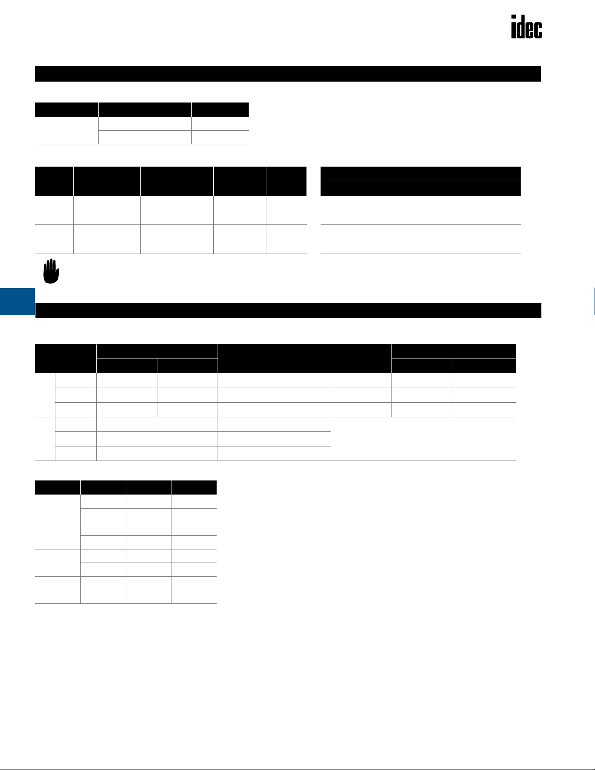
Relays RSS Series
Part Numbers
RSS Series — Panel Mount Solid State Relays
Key features of the RSS series include:
• Input status LED Indicator
• Dual SCR output
• Direct bond copper substrate
• Internal transient protection – built-in snubber
• EMC compliant (level 3)
• Photo isolation
• 1200 volt blocking voltage
• 4000 volt optical isolation
• Zero voltage turn-on
• 100% tested at rated current
• High surge capability
• Optional finger-safe
terminal cover (RSS-CVR)
UL Recognized
File No. E194577
Series RSSDN RSSAN
Voltage Range
Input Current
Pick Up Voltage
Drop Out Voltage
Dielectric Strength
(Input-Output-Base)
Input Specifications
Capacitance
(Input to Output)
Rev. Voltage Protection
Current (continuous)
1-Cycle Surge Current
1-Second Surge Current
Minimum Holding Current
Voltage Drop
at Rated Current
Voltage Range
Contact
Over Voltage Rating
Frequency Range
Off-State Leakage
Output Specifications
at Rated Voltage
Turn-On Time
Turn-Off Time
Zero Voltage Switching
Static DV/DT
Commutating DV/T
4 to 32V DC 90 to 280V AC
current regulated (10mA)
4V DC 90V AC
1V DC 10V AC
4000 RMS (min) 4000 RMS (min)
8pF 8pF
Yes (–32VDC) N/A
10A 25A 50A 75A 90A
150A 300A 750A 1000A 1200A
30A 75A 150A 225A 300A
50mA 50mA 100mA 100mA 100mA
1.6V (maximum)
48 - 660V AC
1 Form A (SPST-NO)
1200 PIV
47 to 80Hz
20mA (maximum)
1/2 cycle @ 60Hz
1/2 cycle @ 60Hz
Yes
200V/µsec
Snubbed for 0.5 power factor at rated load
10, 25, 50, 75, 90A Current Ratings
48V AC to 660V AC Output Ratings
E
Part Numbers: RSS Series
Continuous Output Current DC Input AC Input
10A RSSDN-10A RSSAN-10A
25A RSSDN-25A RSSAN-25A
50A RSSDN-50A RSSAN-50A
75A RSSDN-75A RSSAN-75A
90A RSSDN-90A RSSAN-90A
2.The fingersafe cover is part no. RSS-CVR.
www.idec.com
USA: (800) 262-IDEC or (408) 747-0550, Canada (888) 317-IDEC
E-35

Relays RSS Series
At higher voltages, the current will be
correspondingly higher.
Recommended Loads
Lamp Loads
Transformer Loads
Transformer loads sometimes result in severe inrush current when the transformer saturates during the first cycle. Use a relay rated for this surge, which
has a 1/2 cycle surge current greater than the maximum applied line voltage ÷
the transformer’s primary resistance (approximately 10x rated current).
Recommended Loads
SSR Rating at 120V AC at 240V AC
2A 150VA 300VA
4A 200VA 400VA
10A 500VA 1KVA
25A 1KVA 2KVA
50A 2KVA 4KVA
Heater Loads
When using solid state relays for driving heaters where the load is switched
on and off rapidly and continuously, severe thermal stress will result. In such
cases, use an SSR relay at no more than 75% of the rating.
Recommended Loads
E
SSR Rating at 120V AC at 240V AC
2A 250W 500W
4A 400W 800W
10A 1KW 2KW
25A 2KW 4KW
50A 3KW 6KW
Solenoid Valves and Contactors
RSS relays use high-noise immunity circuitry with a snubber to handle the
electrical noise generated by inductive loads.
Recommended Loads
SSR Rating at 120V AC at 240V AC
2A 250W 500W
4A 400W 800W
10A 900W 1,800W
25A 2,100W 4,200W
50A 3,800W 7,500W
Zero voltage switching is ideal for driving incandescent lamps,
since the cold filiment will not be subjected to a large inrush
current. Using a zero-switched SSR will reduce inrush current
and prolong lamp life.
Recommended Loads
SSR Rating at 120V AC at 240V AC
2A 2A 2A
4A 3A 3A
10A 1KW 2KW
25A 2KW 4KW
50A 3KW 6KW
Calculating Input Current
RSS relays (DC in/AC out) have a circuit with 1,000Ω in series
with opto-couplers LEDs. At 4V input, the relay will turn on with
3mA: [4V – (1V drop across LED) = 3V]; [3V ÷ 1,000Ω = 3mA].
[(Input Voltage – 1) ÷ Impedance] = Input Current (A)
4
3 2
AC INPUT EQUIVALENT CIRCUIT
4
3 2
DC INPUT EQUIVALENT CIRCUIT
TRIGGER
CIRCUIT
TRIGGER
CIRCUIT
1
SNUBBER
1
SNUBBER
RSS series relays provide a highly reliable means of switching AC loads when
applied properly. Read the following technical notes prior to installing IDEC’s
quality solid state relays.
UL Motor Load Ratings
Part Number 120V 240V 480V
10A 1/2 3/4 3/4
25A 1/2 3/4 3/4
50A 3/4 11/
2
75A 3/4 5 5
90A 3/4 5 5
E-36 www.idec.com USA: (800) 262-IDEC or (408) 747-0550, Canada (888) 317-IDEC
11/
2

Relays RSS Series
Technical Notes
Environment
Do not install SSRs near sources of excessive heat. Make sure applications are dry and well ventilated.
If SSRs must be installed in an environment subject to high temperatures or poor ventilation, or if SSRs are mounted collectively, reduce the load current so that it
does not approach the ambient temperature-load current recommendation. (See the Temperature Derating Curves on the following page.)
When SSRs are used with inductive loads, suppress the inrush current to half of the peak surge current.
Heat Sinks
Heat sinks are recommended for 10, 25, 50, 75, and 90 amp rated solid state relays depending on ambient temperature and mounting position. The recommended
heat sink dimensions and material are shown in the table:
Output Rating Dimensions Material
10A 12" x 12" x 1/8" Aluminum (black anodized)
25A 12" x 12" x 1/8" (DC/AC) Aluminum (black anodized)
25A 15" x 15" x 1/8" (AC/AC) Aluminum (black anodized)
50A 15" x 15" x 1/8" Aluminum (black anodized)
75A 17" x 17" x 1/8" Aluminum (black anodized)
90A 17" x 17" x 1/8" Aluminum (black anodized)
Using a thermal compound between the base of the SSR and the heat sink for heat dissipation is recommended.
Wiring
Locate SSRs as far from motor leads as possible to prevent malfunction from induced current.
Use shielded wires for input leads when they are exposed to a source of induced current.
Mounting
Provide sufficient ventilation.
Use #6 – 32 screws, flat washers, and lock washers to secure mounting on heat sinks.
Vertical mounting is recommended to allow air to flow unimpeded. Horizontal or inverted mounting is possible, but the SSR must be derated according to the derating curves on the following page.
Additional Information
Do not exceed the load voltage and current specifications.
A small-capacity load may not turn off due to the leackage current present after the SSR has turned off. If this is the case, use a resistor in parallel with the load
to shunt the leakage current.
Observe the polarity of input terminals. Failure to do so may cause damage to the SSR.
When the SSR output is subjected to a higher than rated voltage, a varistor or other element should be connected to the output terminals to absorb the over-voltage.
When the input signal contains a ripple voltage, the lowest ripple amplitude should exceed the minimum pick-up voltage of 4V.
Over 4V
0V
Lowest Voltage
E
www.idec.com
USA: (800) 262-IDEC or (408) 747-0550, Canada (888) 317-IDEC
E-37

Relays RSS Series
Temperature Derating Curves: RSS Series
E
RSS Series
Derating Curve
10-Amp and 25-Amp
25
Mounted on Heatsink
20
15
10
25 Amp Unit-Free Air
5
10 Amp Unit-Free Air
RMS On-State Current (Amps)
For information on heat sink size, refer to the Technical Notes on
the previous page.
30
20
Relay Base Temp (°C)
10 Amp
50 60 70 90
40
Heatsink
80
100
RSS Dimensions
Derating Curve
50-Amp, 75-Amp, and 90-Amp
100
80
90 Amp
75 Amp
Mounted on
60
50 Amp Heatsink
50
20
RMS On-State Current (Amps)
20
1.9" (48.26mm)
90 Amp Unit-Free Air
50 Amp-Free Air
30
Relay Base Temp (°C)
50 60 70 90
40
Mounted on Heatsink
Heatsink
80
100
8-32 Pan Head Screw
Large Saddle Clamp
6-32 Pan Head Screw
Small Saddle Clamp
0.09" (2.3mm)
1.1" (27.9mm)
1
1.7" (43.2mm)
2.25" (57.2mm)
-4
R 0.265" (6.7mm)
1.75" (44.5mm)
1.0" (25.4mm)
2
3+
ø0.187"
(4.5mm)
1.88" (47.6mm)
0.2"
(4.8mm)
0.95" (24.1mm)
2.4" (6.96mm)
2.65" (67.31mm)
1.075"
(27.31mm)
0.79"
(20.07mm)
Material: Polycarbonate-Clear
0.5" (12.70mm)
0.37" (9.40mm)
E-38 www.idec.com USA: (800) 262-IDEC or (408) 747-0550, Canada (888) 317-IDEC
 Loading...