

Page 1
RU
Relays & Sockets
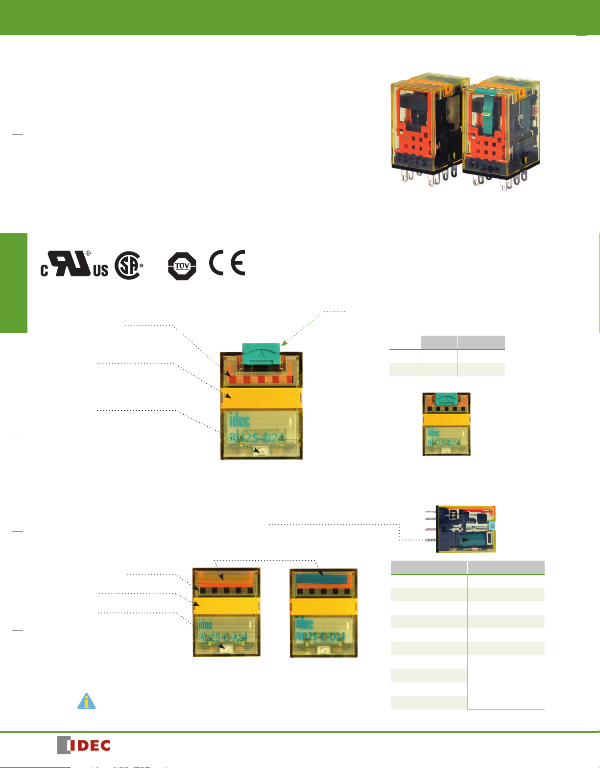
RU Series Universal Relays
Key features:
• Full featured universal miniature relays
• Designed with environment taken into consideration
• Two terminal styles: plug-in and PCB mount
Switches & Pilot LightsSignaling LightsRelays & SocketsTimersContactorsTerminal BlocksCircuit Breakers
• Non-polarized LED indicator
• No internal wires, lead-free construction
• Cadmium-free contacts
• Mechanical ag indicator
• Manual latching lever with color coding for AC or DC coil
• Snap-on yellow marking plate; optional marking plates are available in four other colors
• Maximum contact ratings: 10A (RU2), 6A (RU4), 3A (RU42)
• UL Recognized, CSA Certied, EN Compliant
With Latching or Momentary Lever
Mechanical Indicator*
The contact position can be conrmed through
the ve small windows.
Marking Plate
Standard yellow marking plate is easily replaced
with optional marking plates in four colors for
easy identication of relays.
LED Indicator*
Non-polarized green LED indicator is standard
provision for plug-in terminal, latching lever
types
Standard (without lever)
AC/DC Color Marking
For identication of AC or DC coils.
AC coil: Yellow
DC coil: Blue
Mechanical Indicator*
Marking Plate
LED Indicator*
Non-polarized green LED indicator is standard
provision for plug-in terminal types.
*Not available on PCB type.
EN61810-1
AC Coil DC Coil
Latching and Momentary Lever
Using the lever, operation can be checked without energizing the coil.
The lever is color coded for AC and DC coils.
Latching Momentary
AC coil: Orange Red
DC coil: Green Blue
In Normal Operation
Note: Turn off the power to the relay coil when using the latching
lever. After checking the operation, return the latching lever
in the normal position.
Coil Voltage Tape Color
24V AC White
100 to 110V AC Clear
110 to 120V AC Blue
200 to 220V AC Black
220 to 240V AC Red
24V DC Green
6V DC
12V DC
48V DC
110V DC
Voltage marking on
yellow tape
890
1705151135
Page 2
•
Relays & Sockets
RU
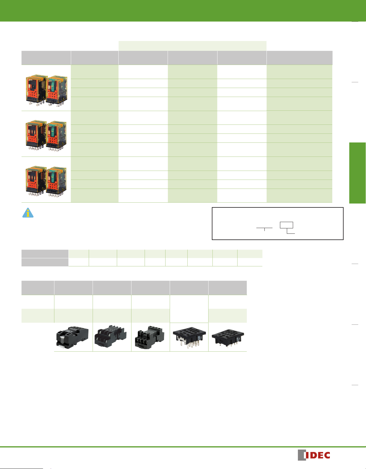
Part Number Selection
Part Number
Contact Model Standard With Latching Lever With Momentary Lever
DPDT (10A)
4PDT (6A)
4PDT Bifurcated (3A)
1. Plug-in terminal models have an LED indicator and a mechanical indicator as standard.
2. PCB models do not have an LED indicator or a mechanical indicator.
Standard
With RC (AC coil only)
With diode (DC coil only)
PCB
Standard
With RC (AC coil only)
With diode (DC coil only)
PCB
Standard
With RC (AC coil only)
With diode (DC coil only)
PCB
RU2S-C-0 RU2S-0 RU2S-M-0
0 RU2S-R-0 RU2S-MR-0
RU2S-CR-
RU2S-CD-
0 RU2S-D-0 RU2S-MD-0
0
RU2V-NF-
RU4S-C-0 RU4S-0 RU4S-M-0
0 RU4S-R-0 RU4S-MR-0
RU4S-CR-
RU4S-CD-
0 RU4S-D-0 RU4S-MD-0
0
RU4V-NF-
RU42S-C-0 RU42S-0 RU42S-M-0
RU42S-CR-
RU42S-CD-
RU42V-NF-
0 RU42S-R-0 RU42S-MR-0
0 RU42S-D-0 RU42S-MD-0
0
— —
— —
— —
Ordering Information
When ordering, specify the Part No. and coil voltage code:
(example) RU2S-C A110
Part No. Coil Voltage Code
Switches & Pilot Lights Signaling Lights Relays & Sockets Timers Contactors Terminal Blocks Circuit Breakers
Coil Voltage Code
(Standard Stock in bold)
A24, A110, A220
D6, D12, D24, D48, D110
A110, A220
D6, D12, D24, D48, D110
A24, A110, A220
D6, D12, D24, D48, D110
A24, A110, A220
D6, D12, D24, D48, D110
A110, A220
D6, D12, D24, D48, D110
A24, A110, A220
D6, D12, D24, D48, D110
A24, A110, A220
D6, D12, D24, D48, D110
A110, A220
D6, D12, D24, D48, D110
A24, A110, A220
D6, D12, D24, D48, D110
Coil Voltage Table
Coil Voltage Code A24 A110 A220 D6 D12 D24 D48 D110
Coil Rating 24V AC 110-120V AC 220-240V AC 6V DC 12V DC 24V DC 48V DC 110V DC
Sockets
Relays
RU2S (DPDT) SU2S-11L SM2S-05 SM2S-05C
RU4S (4PDT)
RU42S (4PDT)
Spring Clamp
DIN Rail Mount
SU4S-11L SY4S-05 SY4S-05C
Standard DIN
Rail Mount
Finger-safe DIN
Rail Mount
Panel Mount PCB Mount
SM2S-61
SY4S-51
SM2S-62
SY4S-61
SY4S-62
1705151135
891
Page 3
RU
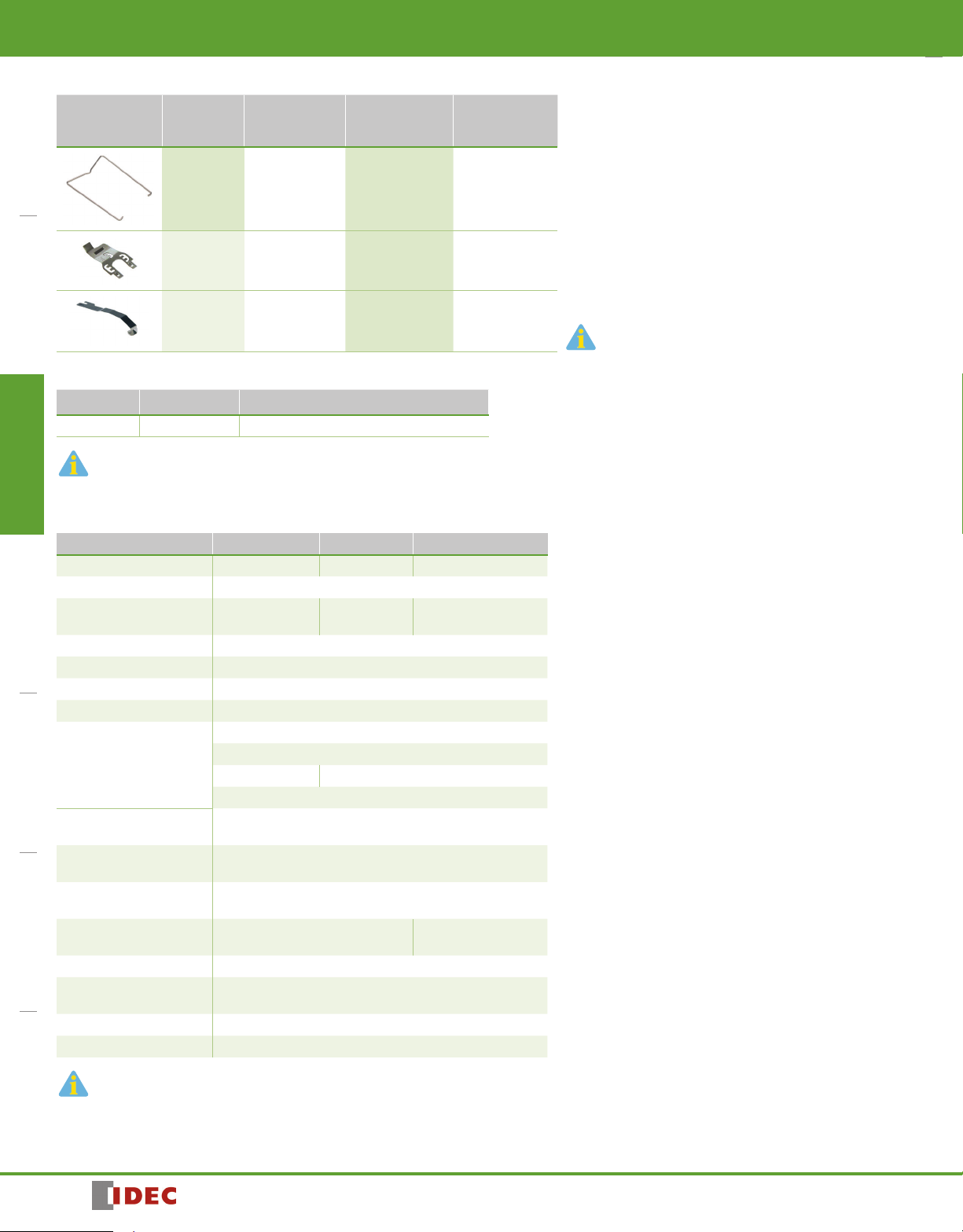
Hold Down Springs & Clips
Appearance Item Relay
For DIN
Mount Socket
Relays & Sockets
For Through
Panel & PCB
Mount Socket
Switches & Pilot LightsSignaling LightsRelays & SocketsTimersContactorsTerminal BlocksCircuit Breakers
Pullover Wire
Spring
Leaf Spring
(side latch)
Leaf Spring
(top latch)
RU2S/RU4S/
RU42S
RU2S/RU4S/
RU42S
RU2S/RU4S/
RU42S
SY4S-02F1 SY4S-51F1
SFA-202* SFA-302*
SFA-101* SFA-301*
Accessories
Name Part Number Color Code *
Marking Plate RU9Z-P* A (orange), G (green), S (blue), W (white), Y (yellow)
Specify a color code when ordering. The marking plate can be removed from the relay by inserting
a at screwdriver under the marking plate.
Specications
Model (Contact) RU2 (DPDT) RU4 (4PDT) RU42 (4PDT-bifurcated)
Contact Material Silver alloy Silver (gold clad) Silver-nickel (gold clad)
Contact Resistance
Minimum
Applicable Load
Operating Time
Release Time
Power Consumption AC: 1.1 to 1.4VA (50 Hz), 0.9 to 1.2VA (60 Hz) DC: 0.9 to 1.0W
Insulation Resistance 100MΩ minimum (500V DC megger)
Dielectric Strength
Operating Frequency
Vibration Resistance
Shock Resistance
Mechanical Life
Electrical Life
Operating
Temperature 5
Operating Humidity 5 to 85% RH (no condensation)
Weight Approx. 35g
1. Measured using 5V DC, 1A voltage drop method
2. Measured at operating frequency of 120 operations/min (failure rate level P, reference value)
3. Measured at the rated voltage (at 20°C), excluding contact bouncing;
Release time of AC relays with RC: 25 ms maximum
Release time of DC relays with diode: 40 ms maximum
1
2
3
3
24V DC, 5 mA
(reference value)
50 mΩ maximum
1V DC, 1 mA 1V DC, 0.1 mA
20 ms maximum
20 ms maximum
Between contact and coil: 2500V AC, 1 minute
Between contacts of different poles:
2500V AC, 1 minute 2000V AC, 1 minute
Between contacts of the same pole: 1000V AC, 1 minute
Electrical: 1800 operations/h maximum
Mechanical: 18,000 operations/h maximum
Damage limits: 10 to 55 Hz, amplitude 0.5 mm
Operating extremes: 10 to 55 Hz, amplitude 0.5 mm
2
Damage limits: 1000 m/s
(100G)
Operating extremes: 150 m/s2 (15G)
AC: 50,000,000 operations
DC: 100,000,000 operations
4
See table on page 894
50,000,000 operations
PCB model: –55 to +70°C (no freezing)
Blade model: –55 to +60°C (no freezing)
Note: Order 2 pieces for each relay
4. Contact Load and Electrical Life (at ambient temperature 20°C)
5. Measured at the rated voltage.
892
1705151135
Page 4

•
Relays & Sockets
RU
Accessories
Item Appearance Use with Part No. Remarks
Aluminum
DIN Rail
(1 meter length)
DIN Rail End
Stop
Replacement
Hold-Down
Spring Anchor
All DIN rail sockets BNDN1000
DIN rail BNL5 9.1 mm wide.
Horseshoe clip for DIN rail
sockets
Y778-011
The BNDN1000 is designed to accommodate DIN mount sockets.
Made of durable extruded aluminum, the BNDN1000 measures 0.413
(10.5mm) in height and 1.37 (35mm) in width (DIN standard). Standard
length is 39” (1,000mm).
For use on DIN rail mount socket when using pullover wire hold down
spring. 2 pieces included with each socket.
Coil Ratings
Rated Voltage (V)
AC
(50/60 Hz)
DC
1. The rated current includes the current of the LED indicator.
24 A24 49.3 42.5 164
220-240 A220 4.2-5.0 3.6-4.2 18,230
6 D6 155 40
12 D12 80 160
24 D24 44.7 605
48 D48 18 2,560
110 D110 8.9 12,100
Coil
Voltage
Code
Rated Current (mA)
±15% (at 20°C)
50 Hz 60 Hz
Coil Resistance (Ω)
±10% (at 20°C)
Maximum Continuous
Applied Voltage
110% 80% maximum 30% minimum110-120 A110 8.4-10.0 7.1-8.2 4,550
110% 80% maximum 10% minimum
Switches & Pilot Lights Signaling Lights Relays & Sockets Timers Contactors Terminal Blocks Circuit Breakers
Operating Characteristics (values at 20°C)
Pickup Voltage Dropout Voltage
Surge Suppressor Ratings
Model Ratings
AC Coil With RC
DC Coil With Diode
RC series circuit
R: 20 kΩ, C: 0.033 µF
Diode reverse voltage: 1000V
Diode forward current: 1A
Contact Ratings
Maximum Contact Capacity
Contact
DPDT 10A
4PDT 6A
4PDT
bifurcated
Continuous
Current
3A
1. On 4PDT relays, the maximum allowable total current of neighboring two poles is 6A. At the rated
load, make sure that the total current of neighboring two poles does not exceed 6A (3A + 3A = 6A).
2. Inductive load for the rated load — cos ø = 0.3, L/R = 7 ms
Allowable Contact Power
Resistive Load Inductive Load Res. Load Ind. Load
2500VA AC 1250VA AC 250 AC 10A 5A
300W DC 150W DC 30 DC 10A 5A
1500VA AC 600VA AC 250 AC 6A 0.8A
180W DC 90W DC 30 DC 6A 1.5A
750VA AC 200VA AC 250 AC 3A 0.8A
90W DC 45W DC 30 DC 3A 1.5A
Voltage
(V)
Rated Load
UL and c-UL Ratings
Voltage
250V AC 10A — 3A — 6A — — 1/10HP —
30V DC 10A 6A 3A — — — — — —
CSA Ratings
Voltage
250V AC 3A
30V DC 3A
Resistive General Use Horse Power Rating
RU2 RU4 RU42 RU2 RU4 RU42 RU2 RU4 RU42
TÜV Ratings
Resistive
RU42
Voltage
250V AC 10A 6A 3A 5A 0.8A 0.8A
30V DC 10A 6A 3A 5A 1.5A 1.5A
Resistive Inductive
RU2 RU4 RU42 RU2 RU4 RU42
1705151135
893
Page 5

RU
250V AC
Load Current (A)
(¥ 10,000 operations)
250V AC
Load Current (A)
(¥ 10,000 operations)
250V AC
Load Current (A)
(¥ 10,000 operations)
250V AC/30V DC
Load Current (A)
(¥ 10,000 operations)
Load Current (A)
(¥ 10,000 operations)
250V AC
Load Current (A)
(¥ 10,000 operations)
250V AC
AC resistive
Load Voltage (V)
Load Current (A)
Relays & Sockets
Socket Specications
Sockets Terminal Electrical Rating Wire Size Torque
SU2S-11L Spring clamp terminals 250V/10A 24-16 AWG —
SU4S-11L Spring clamp terminals 250V/6A (using RU4), 10A (using RU2) 24-16 AWG —
DIN Rail Mount
Sockets
Switches & Pilot LightsSignaling LightsRelays & SocketsTimersContactorsTerminal BlocksCircuit Breakers
SM2S-05 M3 screw with captive wire clamp 300V, 10A Maximum up to 2–#14AWG 5.5 - 9in•lbs
SM2S-05C M3 screw with captive wire clamp, ngersafe 300V, 10A Maximum up to 2–#14AWG 5.5 - 9in•lbs
SY4S-05 M3 screw with captive wire clamp 300V, 7A (using RU4), 10A (using RU2) Maximum up to 2–#14AWG 5.5 - 9in•lbs
SY4S-05C M3 screw with captive wire clamp, ngersafe 300V, 7A (using RU4), 10A (using RU2) Maximum up to 2–#14AWG 5.5 - 9in•lbs
Through Panel
Mount Socket
PCB Mount Socket
SY4S-51 Solder 300V, 7A — —
SY4S-61 PCB mount 300V, 7A — —
SY4S-62 PCB mount 250V, 7A — —
Electrical Life Curves
RU2 (Resistive Load) RU4 (Resistive Load) RU42 (Resistive Load)
30V DC
110V DC
30V DC
110V DC
100
10
1
6 3 10.50.1
0.02 6310.50.1
1000
100
30V DC
110V DC
10
1
10 5 10.50.1
1000
100
10
1
RU2 (Inductive Load) RU4 (Inductive Load) RU42 (Inductive Load)
1000
100
10
1
110V DC
AC: cos ø = 0.3
DC: L/R = 7 ms
0.1 0.5 1 5 10
100
10
1
AC: cos ø = 0.3
DC: L/R = 7 ms
0.1 0.50.02
30V DC
110V DC
100
10
1
AC: cos ø = 0.3
DC: L/R = 7 ms
0.1 0.50.02
30V DC
110V DC
Maximum Switching Current
RU2 RU4 RU42 (Bifurcated)
10
5
1
0.1
894
DC resistive
DC inductive
L/R = 7 ms
10 30 100 250 500
AC inductive
(cos ø = 0.3)
1705151135
Page 6

•
Relays & Sockets
120
70
Ambient Temperature (C)
Temperature Rise (C)
070
120
Ambient Temperature (C)
Temperature Rise (C)
070
120
Ambient Temperature (C)
Temperature Rise (C)
070
120
Ambient Temperature (C)
Temperature Rise (C)
120
70
Ambient Temperature (C)
Temperature Rise (C)
120
70
Ambient Temperature (C)
Temperature Rise (C)
RU
Ambient Temperature vs. Temperature Rise Curves
RU2 (AC Coil, 50 Hz) RU2 (AC Coil, 60 Hz) RU2 (DC Coil)
110
100
90
80
70
60
50
40
30
20
10
Load current
10A ¥ 2 poles
Load current
5A ¥ 2 poles
No load current
6050403020100
110
100
90
80
70
60
50
40
30
20
10
Load current
10A ¥ 2 poles
Load current
5A ¥ 2 poles
No load current
010203040506
RU4/RU42 (AC Coil, 50 Hz) RU4/RU42 (AC Coil, 60 Hz) RU4/RU42 (DC Coil)
110
100
90
80
70
60
50
40
30
20
10
010203040506
Load current
3A ¥ 4 poles
Load current
6A ¥ 2 poles
No load current
110
100
90
80
70
60
50
40
30
20
10
Load current
3A ¥ 4 poles
Load current
6A ¥ 2 poles
No load current
6050403020100
110
100
90
80
70
60
50
40
30
20
10
110
100
90
80
70
60
50
40
30
20
10
Load current
10A ¥ 2 poles
Load current
5A ¥ 2 poles
010203040506
Load current
3A ¥ 4 poles
Load current
6A ¥ 2 poles
No load current
Switches & Pilot Lights Signaling Lights Relays & Sockets Timers Contactors Terminal Blocks Circuit Breakers
No load current
6050403020100
The above temperature rise curves show the characteristics when 100% the rated coil voltage is applied.
The heat resistance of the coil is 120°C. The slant dashed line indicates the allowable temperature rise for the coil at different ambient temperatures.
Load current 6A x 2 poles is for the RU4 models only.
1705151135
895
Page 7

RU
Over 24V AC/DC coil
(1)12 (4)42
Over 24V DC coil
(4)42(1)12
Over 24V AC/DC coil
(4)42(3)32(2)22(1)12
Over 24V DC coil
(1)12 (2)22 (3)32 (4)42
Latching
Lever
AC: Orange
DC: Green
Marking Plate (yellow)
LED Indicator
(green)
Marking Plate
Removal Slot
Mechanical Indicator Window
Marking Plate (yellow)
Marking Plate
Removal Slot
Color Marking
A
C: Yellow
DC: Blue
Relays & Sockets
Internal Connection (View from Bottom)
RU2S-* Standard RU2S-*R with RC RU2S-*D With Diode RU2V-NF-*
(4)42(1)12
(8)44(5)14
(12)41(9)11
(14)A2
Switches & Pilot LightsSignaling LightsRelays & SocketsTimersContactorsTerminal BlocksCircuit Breakers
(5)14 (8)44
(9)11 (12)41
(13)A1
(14)A2
(13)A1
(8)44(5)14
(12)41(9)11
(14)A2
(13)A1
(13)A1
(4)42(1)12
(8)44(5)14
(12)41(9)11
(14)A2
24V AC/DC coil or less
(4)42(1)12
(8)44(5)14
(12)41(9)11
(13)A1
(14)A2
24V DC coil or less
(1)12 (4)42
(5)14 (8)44
(9)11 (12)41
(13)A1
(14)A2
RU4S-*/RU42S-* Standard RU4S-*R/RU42S-*R With RC RU4S-*D/RU42S-*D With Diode RU4V-NF-*/RU42V-NF-*
(4)42(3)32(2)22(1)12
(8)44(7)34(6)24(5)14
(12)41(11)31(10)21(9)11
(13)A1
(14)A2
24V AC/DC coil or less
(1)12 (2)22 (3)32 (4)42
(5)14 (6)24 (7)34 (8)44
(9)11 (10)21 (11)31 (12)41
(13)A1
(14)A2
(13)A1
(8)44(7)34(6)24(5)14
(12)41(11)31(10)21(9)11
(14)A2
(5)14 (6)24 (7)34 (8)44
(9)11 (10)21 (11)31 (12)41
(13)A1
(14)A2
24V DC coil or less
(4)42(3)32(2)22(1)12
(8)44(7)34(6)24(5)14
(12)41(11)31(10)21(9)11
(13)A1
(14)A2
(13)A1
Dimensions (mm)
(4)42(3)32(2)22(1)12
(8)44(7)34(6)24(5)14
(12)41(11)31(10)21(9)11
(14)A2
RU2S RU2V
35.06.4
2.6
0.5
ø1.2 ¥ 2.2 Hole
21.0
14
58912
13 14
27.5
Marking plate removal slot is provided only on one side.
Insert a at screwdriver into the slot to remove the marking
plate.
0.5
21.0
27.5
Mounting Hole Layout
7.0
12.74.1
8-ø1 Holes
6.4
35.0
13.2
0.8
2.6
4.0
13.2
All dimensions in mm.
0.5
896
1705151135
Page 8

•
Relays & Sockets
Latching
Lever
AC: Orange
DC: Green
LED Indicator
(green)
Marking Plate
Removal Slot
Mechanical Indicator Window
Marking Plate (yellow)
Marking Plate (yellow)
Marking Plate
Removal Slot
Color Marking
A
C: Yellow
DC: Blue
31
80
38.3
31
80
cannot be used.
623 0.7
31.5
Terminal Arrangement
30
RU
Dimensions con’t (mm)
RU4S/RU42S RU4V/RU42V
35.0
0.5
1211109
ø1.2 × 2.2 Hole
1413
8
4321
765
21.0
27.5
Marking plate removal slot is provided only on one side.
Insert a at screwdriver into the slot to remove the marking
plate.
6.4
2.6
Mounting Hole Layout
0.5
21.0
27.5
7.0
4.1 12.7
14-ø1 Holes
6.4
35.0
4.0
4.4
0.5
3-4.4
0.8
2.6
13.2
All dimensions in mm.
Switches & Pilot Lights Signaling Lights Relays & Sockets Timers Contactors Terminal Blocks Circuit Breakers
Spring Clamp DIN Rail Mount Sockets
SU2S-11L SU4S-11L
28.8
4.4
Standard DIN Rail Mount Sockets
SM2S-05 SY4S-05
30
6
M3 Terminal
Screw
4.2
26
32
38.3
4.8 min.
ø3.2 min.
Terminal Arrangement
12 11 10 9
5678
4321
1314
(
)
Top View
Terminal Arrangement
78
432
14
12 1110
(
Top View
56
1
13
9
)
Terminal Arrangement
912
2-ø3.2
Mounting Holes
24.0
37.5
Ring terminals
cannot be used.
18
DIN Rail
(BNDN)
45
18.5
25
2-ø4.2 Mounting Holes
(or M4 Tapped Holes)
26
4 max.
5.9 max.
4.8 min.
ø3.2 min.
8 5
14 13
(
Top View
8
4
14
12
(
Top View
14
28.8
)
5
1
13
9
)
4.4
6
M3 Terminal
Screw
623 0.7
4.2
26
37.5
32
31.5
DIN Rail
18
(BNDN)
45
18.5
25
24.0
4 max.
5.9 max.
2-ø3.2
Mounting Holes
Ring terminals
2-ø4.2 Mounting Holes
(or M4 Tapped Holes)
26
1705151135
897
Page 9

RU
30
64
1.6
Terminal Arrangement
30
64
1.6
35.5
31
13.2
13.2
Relays & Sockets
Dimensions con’t (mm)
Finger-safe DIN Rail Mount Sockets
SM2S-05C SY4S-05C
35.5
46
2
29
Switches & Pilot LightsSignaling LightsRelays & SocketsTimersContactorsTerminal BlocksCircuit Breakers
6
M3 Terminal
Screw
ø
5.5
4.2
26
PCB Mount Sockets
SM2S-61 SM2S-62
25.4
27
21.2
3
0.3
11
15
1.5
SY4S-61 SY4S-62
Terminal Arrangement
31
27
1.5
21.2
25.4
3
0.3
11
15
DIN Rail
(BNDN)
25
18
Ring terminals
18.2
cannot be used.
Terminal Arrangement
1
5
12
9
13 14
(Bottom View)
* 19.2 min. when using
hold-down springs
3
462
1
5
8
7
12
9
11
10
13
14
(Bottom View)
* 19.2 min. when using
hold-down springs
2-ø4.2 Mounting Holes
(or M4 Tapped Holes)
26
4
8
16.8
14.2 min.*
16.8
14.2 min.*
10.4
8
5
1
4
13
14
12
9
(
)
Top View
13.2
4.1
10.4
1.4
8.8
4.1
1.4
4.4
ø2 holes
9-
(Tolerance 0.1)
13.8 min.
ø2 holes
15-
(Tolerance 0.1)
13.8 min.
9
M3 Terminal
6
Screw
ø
5.5
4.2
46
26
2
DIN Rail
25
(BNDN)
18
18.2
29
2-ø4.2 Mounting Holes
(or M4 Tapped Holes)
26
Ring terminals
cannot be used.
Terminal Arrangement
56
78
432
1
13
14
12 11 10
9
(
)
Top View
13.2
Terminal Arrangement
4
1
5
29
9
21.2
1.5
29
21.2
1.5
3
3
0.3
11
15
Terminal Arrangement
0.3
11
15
9
13
(Bottom View)
3
1
5
7
9
11
10
13
(Bottom View)
8
12
14
462
8
12
14
*
17.2 min. when using a hold-down spring.
13.2 min. when using a hold-down spring for
* *
the relay with check button
4.1
10.4
16.8
1.4
12.2 min.*
*
17.2 min. when using a hold-down spring.
13.2 min. when using a hold-down spring for
**
the relay with check button.
8.8
4.4
4.1
10.4
16.8
1.4
12.2 min.*
8.2 min.**
9
9-ø2 holes
(Tolerance 0.1)
8.2 min.**
9
15-ø2 holes
(Tolerance 0.1)
Through Panel Mount Socket
SY4S-51
Panel Thickness:
1 to 2
31
27
21.2
3
0.3
11
18.7
2.4
898
25.4
Terminal Arrangement
3
2
1
5
7
846
12
10
11
9
13
14
(Bottom View)
[27 (N–1) + 21.4]
0
+0.2
25.6
5.4 min.*
* 10.4 min. when using hold-down springs
+0.5
0
N: No. of sockets mounted
1705151135
 Loading...