

RTE
Key features:
• 20 time ranges and 10 timing functions
• Time delays up to 600 hours
• Space-saving package
• High repeat accuracy of ± 0.2%
Switches & Pilot LightsSignaling LightsRelays & SocketsTimersContactorsTerminal BlocksCircuit Breakers
• ON and timing OUT LED indicators
• Standard 8- or 11-pin and 11-blade termination
• 2 form C delayed output contacts
• 10A Contact Rating
Timers
Timers
RTE
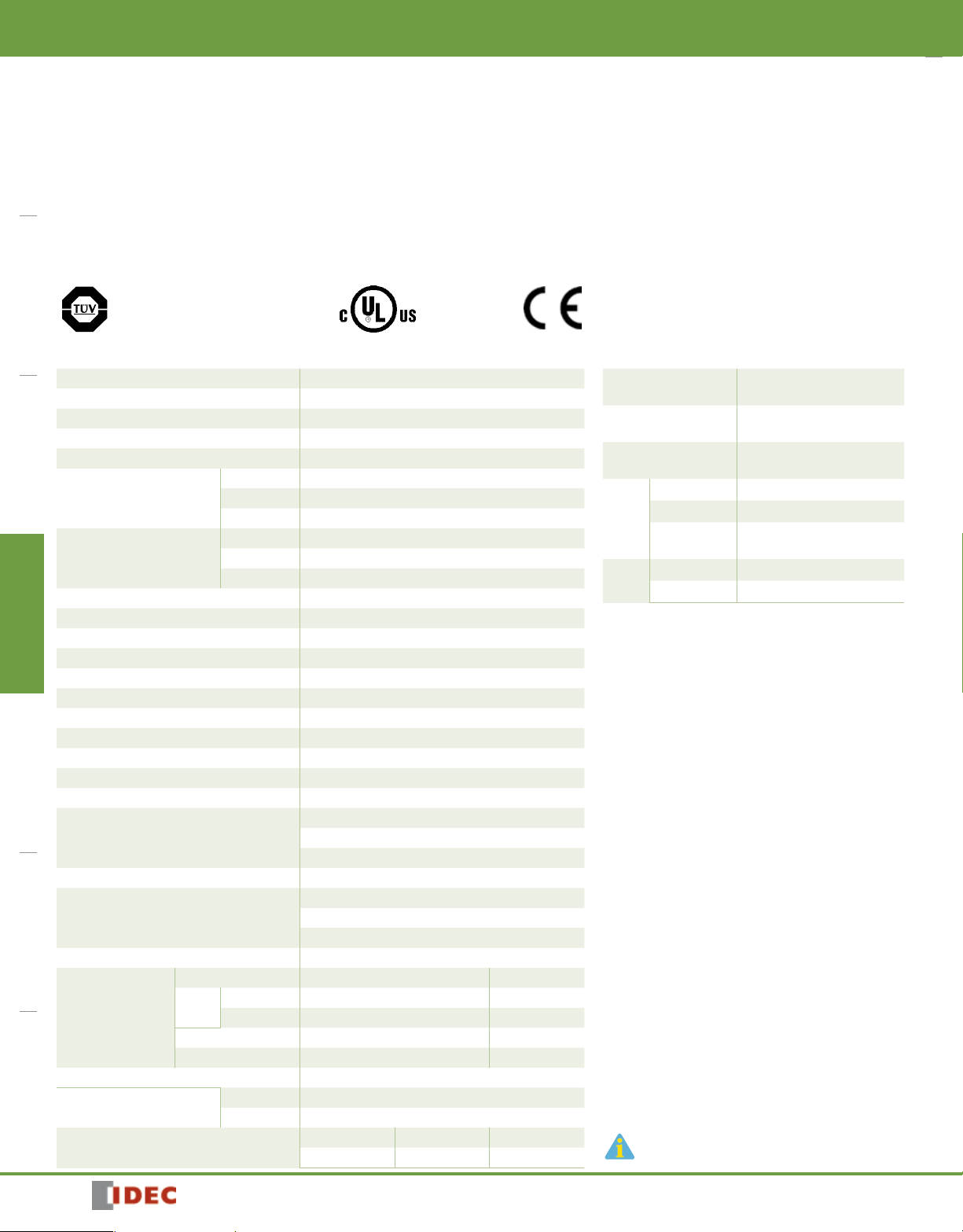
RTE Series — Analog Timers
Cert. No. E9950913332316 (EMC, RTE)
Cert. No. BL960813332355 (LVD, RTE)
UL Listed
File No. E66043
General Specifications Contact Ratings
Operation System Solid state CMOS Circuit
Operation Type Multi-Mode
Time Range 0.1sec to 600 hours
Pollution Degree 2 (IE60664-1)
Over voltage category III (IE60664-1)
AF20 100-240V AC(50/60Hz)
Rated Operational Voltage
Voltage Tolerance
Input off Voltage Rated Voltage x10% minimum
Ambient Operating Temperature -20 to +65ºC (without freezing)
Ambient Storage and Transport Temperature -30 to +75ºC (without freezing)
Relative Humidity 35 to 85%RH (without condensation)
Atmospheric Pressure 80kPa to 110kPa (Operating), 70kPa to 110kPa (Transport)
Reset Time 100msec maximum
Repeat Error ±0.2%, ±20msec*
Voltage Error ±0.2%, ±20msec*
Temperature Error ±0.5%, ±20msec*
Setting Error ±10% maximum
Insulation Resistance 100MΩ minimum (500V DC)
Dielectric Strength
Vibration Resistance 10 to 55Hz amplitude 0.5mm
Shock Resistance
Degree of Protection IP40 (enclosure) (IEC60529)
Power Consumption
(Approx.)
Mounting Position Free
Dimensions
Weight (Approx.)
AD24 24V AC(50/60Hz)/24V DC
D12 12V DC
AF20 85-264V AC(50/60Hz)
AD24 20.4-26.4V AC(50/60Hz)/21.6-26.4V DC
D12 10.8-13.2V DC
Between power and output terminals: 2000V AC, 1 minute
Between contacts of different poles: 2000V AC, 1 minute
Between contacts of the same pole:1000V AC, 1 minute
2
hours in each of 3 axes
Operating extremes: 98m/sec2 (10G)
Damage limits: 490m/sec2 (50G)
3 times in each of 3 axes
TYPE RTE-P1, -B1 RTE-P2, -B2
120V AC/60Hz 6.5VA 6.6VA
AF20
240V AC/60Hz 11.6VA 11.6VA
24V AC 60Hz/DC 3.4VA/1.7W 3.5VA/1.7W
D12 1.6W 1.6W
RTE-P1, P2 40Hx 36W x 77.9D mm
RTE-B1, B2 40Hx 36W x 74.9D mm
RTE-P1 RTE-P2 RTE-B1, -B2
87g 89g 85g
Contact Configuration
Allowable Voltage /
Allowable Current
Maximum Permissible
Operating Frequency
Resistive 10A 240V AC, 30V DC
Rated
Inductive 7A 240V AC, 30V DC
Load
Horse Power
Rating
Electrical 500,000 op. minimum (Resistive)
Life
Mechanical 50,000,000 op. minimum
*For the value of the error against a preset
time, whichever the largest, applies.
2 Form C, DPDT
(Delay output)
240V AC, 30V DC / 10A
1800 cycles per hour
1/6 HP 120V AC, 1/3 HP 240V AC
836
www.IDEC.com
Timers
RTE
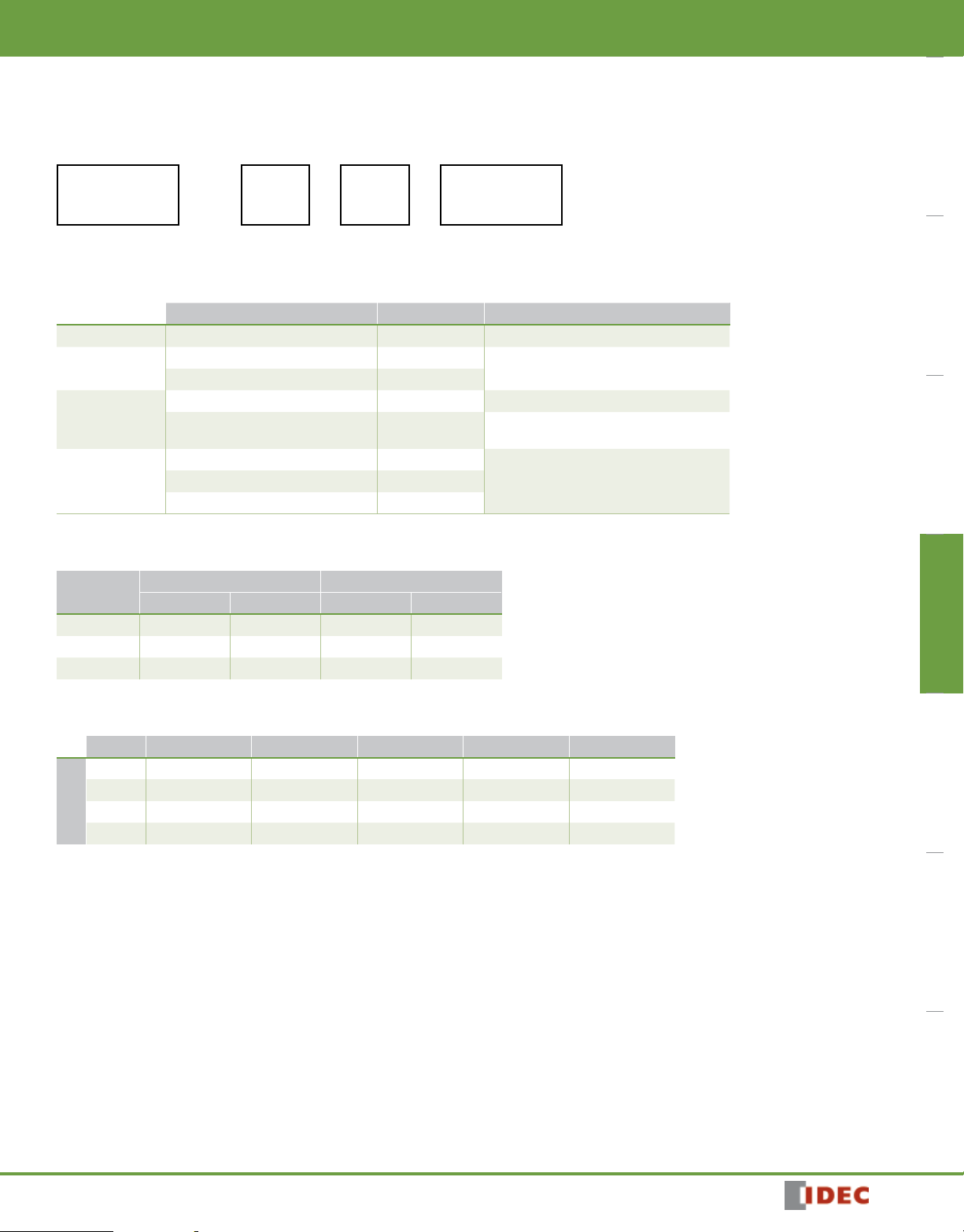
Part Numbering Guide
RTE series part numbers are composed of 4 part number codes. When ordering a RTE series part, select one code from each category.
Example: RTE-P1AF20
RTE — P 1 AF20
j Series k Terminal
Style
Part Numbers: RTE Series
Description Part Number Code Remarks
j Series
k Terminal Style
l Function Group
m Input Voltage
RTE series RTE For internal circuits, see next page.
Pin P
Blade B
ON-delay, interval, cycle OFF, cycle ON 1 Each function group has different timing functions.
ON-delay, cycle OFF, cycle ON, signal ON/
OFF delay, OFF-delay, one-shot
100 to 240V AC(50/60Hz) AF20
24V AC(50/60Hz)/24V DC AD24
12V DC D12
l Function
Group
m Input Voltage
Select one only.
2 See page 832.
Switches & Pilot Lights Signaling Lights Relays & Sockets Timers Contactors Terminal Blocks Circuit Breakers
Part Numbers
Voltage
12V DC RTE-P1D12 RTE-B1D12 RTE-P2D12 RTE-B2D12
24V AC/DC RTE-P1AD24 RTE-B1AD24 RTE-P2AD24 RTE-B2AD24
100-240V AC RTE-P1AF20 RTE-B1AF20 RTE-P2AF20 RTE-B2AF20
Power Triggered Start Input Triggered
8-Pin Blade 11-Pin Blade
Time Range Determined by Time Range Selector and Dial Selector
Dial 0 - 1 0 - 3 0 - 10 0 - 30 0 - 60
Second 0.1 sec - 1 sec 0.1 sec - 3 sec 0.2 sec - 10 sec 0.6 sec - 30 sec 1.2 sec - 60 sec
Minute 1.2 sec - 1 min 3.6 sec - 3 min 12 sec - 10 min 36 sec - 30 min 1.2 min - 60 min
Hour 1.2 min - 1 hr 3.6 min - 3 hr 12 min - 10 hr 36 min - 30 hr 1.2 hr - 60 hr
Range
10 Hours 12 min - 10 hr 36 min - 30 hr 2 hr - 100 hr 6 hr - 300 hr 12 hr - 600 hr
800-262-IDEC (4332) • USA & Canada
837
RTE
RTE-P2
11
10
9
1
2
3
4
5
6
7
8
start
RTE-B2
2
3
A
B
9
1
(~/-)(~/+)
4
5
6
7
8
2
3
A
B
9
1
(~/-)(~/+)
4
5
6
7
8
RTE-B1
start
external
control
signal
external
control
signal
RTE-B2
2
3
A
B
9
1
(~/-)(~/+)
4
5
6
7
8
start
external
control
signal
Switches & Pilot LightsSignaling LightsRelays & SocketsTimersContactorsTerminal BlocksCircuit Breakers
RTE-P1
4
3
2
1
Timers
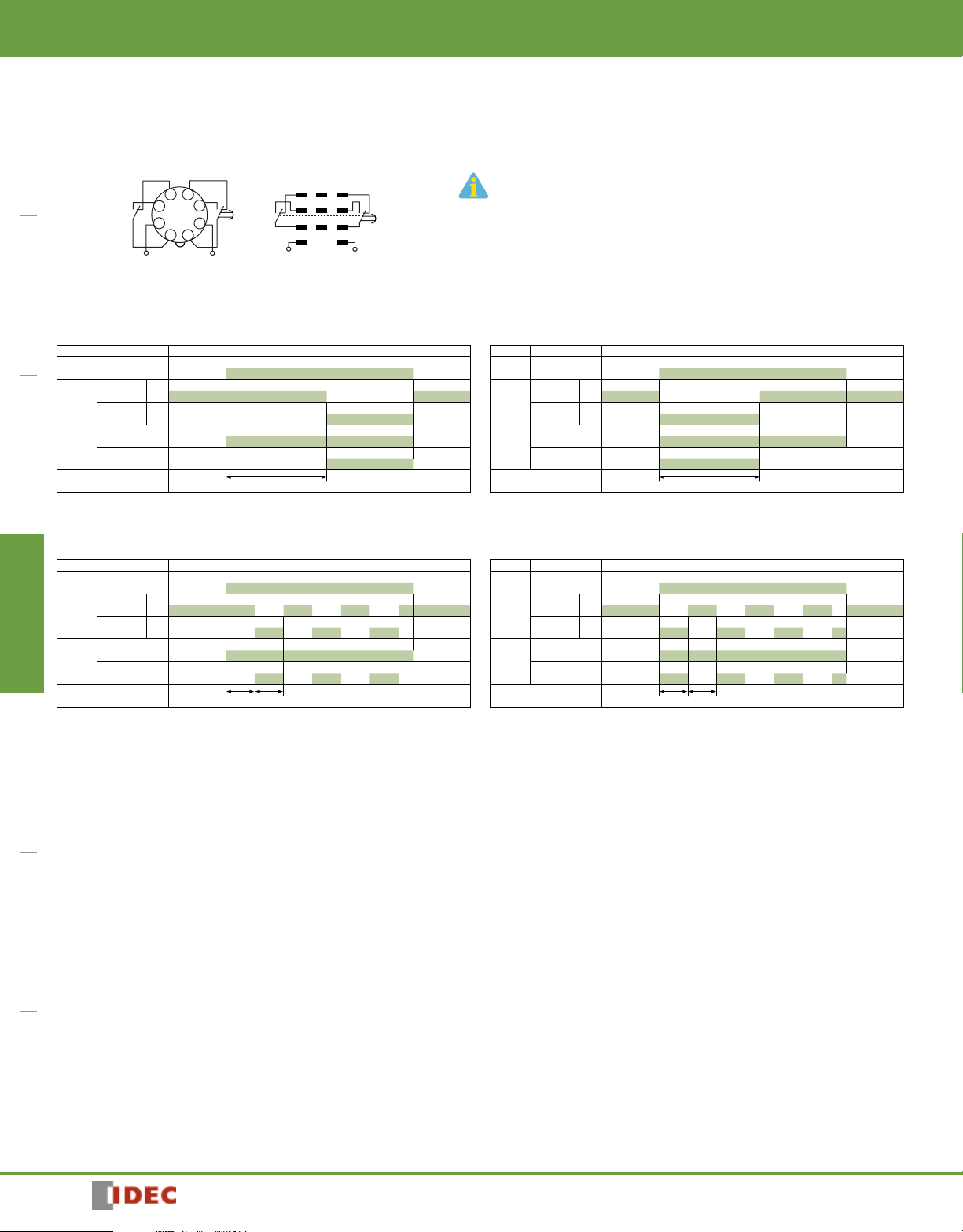
Timing Diagrams
RTE-P1, -B1
RTE-B1
1
3
5
6
7
8
(~/-)(~/+)
2
5
4
6
7
8
9
A
B
(~/-)(~/+)
1. RTE-B1: Do not apply voltage to terminals #2, #5 & #8.
2. IDEC sockets are as follows: RTE-P1: SR2P-06* pin type socket,
RTE-B1: SR3B-05* blade type socket, (*-may be followed by suffix
letter A,B,C or U).
A: ON-Delay 1 (power start)
Set timer for desired delay, apply power to coil. Contacts transfer after preset time has elapsed, and
remain in transferred position until timer is reset. Reset occurs with removal of power.
Item Terminal Number Operation
(1) 2 - 7
Power
(2) A - B
Delayed
Contact
Indicator
Set Time
(1) 1 - 4, 5 - 8
(2) 1 - 7, 3 - 9
(1) 1 - 3, 6 - 8
(2) 4 - 7, 6 - 9
PWR
OUT
(NC)
(NO)
T
C: Cycle 1 (power start, OFF first)
Set timer for desired delay, apply power to coil. First transfer of contacts occurs after preset delay has
elapsed, after the next elapse of preset delay contacts return to original position. The timer now cycles
between on and off as long as power is applied (duty ratio 1:1).
Item Terminal Number Operation
(1) 2 - 7
Power
(2) A - B
Delayed
Contact
Indicator
Set Time
(1) 1 - 4, 5 - 8
(2) 1 - 7, 3 - 9
(1) 1 - 3, 6 - 8
(2) 4 - 7, 6 - 9
PWR
OUT
(NC)
(NO)
T T
B: Interval (power start)
Set timer for desired delay, apply power to coil. Contacts transfer immediately, and return to original
position after preset time has elapsed. Reset occurs with removal of power.
Item Terminal Number Operation
(1) 2 - 7
Power
(2) A - B
Delayed
Contact
Indicator
Set Time
(1) 1 - 4, 5 - 8
(2) 1 - 7, 3 - 9
(1) 1 - 3, 6 - 8
(2) 4 - 7, 6 - 9
PWR
OUT
(NC)
(NO)
T
C: Cycle 3 (power start, ON first)
Functions in same manner as Mode C, with the exception that first transfer of contacts occurs as soon
as power is applies. The ratio is 1:1. Time On = Time Off
Item Terminal Number Operation
(1) 2 - 7
Power
(2) A - B
Delayed
Contact
Indicator
Set Time
(1) 1 - 4, 5 - 8
(2) 1 - 7, 3 - 9
(1) 1 - 3, 6 - 8
(2) 4 - 7, 6 - 9
PWR
OUT
(NC)
(NO)
T T
838
www.IDEC.com

Timers
RTE-B2
2
3
A
B
9
1
(~/-)(~/+)
4
5
6
7
8
2
3
A
B
9
1
(~/-)(~/+)
4
5
6
7
8
RTE-B1
start
external
control
signal
(~/-)(~/+)
RTE
Timing Diagrams con’t
RTE-P2
external
start
control
signal
6
5
7
4
8
9
3
2
10
11
1
A: ON-Delay 2 (signal start)
When a preset time has elapsed after the start input turned on while power is on, the NO output
contact goes on.
Item Terminal Number Operation
(A) 2 - 10
Power
(B) A - B
(A) 5 - 6
Start
(B) 2 - 5
(A) 1 - 4, 8 - 11
(B) 1 - 7, 3 - 9
Delayed
Contact
(A) 1 - 3, 9 - 11
(B) 4 - 7, 6 - 9
PWR
Indicator
OUT
Set Time
C: Cycle 4 (signal start, ON first)
When the start input turns on while power is on, the NO contact goes on. The output oscillates at a
preset cycle (duty ratio 1:1).
Item Terminal Number Operation
(A) 2 - 10
Power
(B) A - B
(A) 5 - 6
Start
(B) 2 - 5
(A) 1 - 4, 8 - 11
(B) 1 - 7, 3 - 9
Delayed
Contact
(A) 1 - 3, 9 - 11
(B) 4 - 7, 6 - 9
PWR
Indicator
OUT
Set Time
E: Signal OFF-Delay
When power is turned on while the start input is on, the NO output contact goes on. When a preset
time has elapsed after the start input turned off, the NO output contact goes off.
Item Terminal Number Operation
(A) 2 - 10
Power
(B) A - B
(A) 5 - 6
Start
(B) 2 - 5
(A) 1 - 4, 8 - 11
(B) 1 - 7, 3 - 9
Delayed
Contact
(A) 1 - 3, 9 - 11
(B) 4 - 7, 6 - 9
PWR
Indicator
OUT
Set Time
(NC)
(NO)
(NC)
(NO)
T T T T T T T T Ta
(NC)
(NO)
T Ta T Ta
external
control
signal
T
RTE-B2
start
1
2
5
4
7
8
A
3
6
9
B
RTE-P2, -B2
1. RTE-P2: Do not apply voltage to terminals #5, #6 & #7.
2. RTE-B2: Do not apply voltage to terminals #2, #5 & #8.
3. IDEC sockets are as follows: RTE-P2: SR3P-05* pin type socket,
RTE-B2: SR3B-05* blade type socket, (*-may be followed by suffix
letter A,B,C or U).
B: Cycle 2 (signal start, OFF first)
When the start input turns on while power is on, the output oscillates at a preset cycle (duty ratio 1:1),
starting while the NO contact off.
Item Terminal Number Operation
(A) 2 - 10
Power
(B) A - B
(A) 5 - 6
Start
(B) 2 - 5
(A) 1 - 4, 8 - 11
(B) 1 - 7, 3 - 9
Delayed
Contact
(A) 1 - 3, 9 - 11
(B) 4 - 7, 6 - 9
PWR
Indicator
OUT
Set Time
D: Signal ON/OFF-Delay
When the start input turns on while power is on, the NO output contact goes on. When a preset time
has elapsed while the start input remains on, the output contact goes off. When the start input turns
off, the NO contact goes on again. When a preset time has elapsed after the start input turned off, the
NO contact goes off.
Item Terminal Number Operation
(A) 2 - 10
Power
(B) A - B
(A) 5 - 6
Start
(B) 2 - 5
(A) 1 - 4, 8 - 11
(B) 1 - 7, 3 - 9
Delayed
Contact
(A) 1 - 3, 9 - 11
(B) 4 - 7, 6 - 9
PWR
Indicator
OUT
Set Time
F: One-Shot (signal start)
When the start input turns on while power is on, the NO output contact goes on. When a preset time
has elapsed, the NO output contact goes off.
Item Terminal Number Operation
(A) 2 - 10
Power
(B) A - B
(A) 5 - 6
Start
(B) 2 - 5
(A) 1 - 4, 8 - 11
(B) 1 - 7, 3 - 9
Delayed
Contact
(A) 1 - 3, 9 - 11
(B) 4 - 7, 6 - 9
PWR
Indicator
OUT
Set Time
(NC)
(NO)
T T T T T T T T T Ta
(NC)
(NO)
T T Ta T T Ta
(NC)
(NO)
Switches & Pilot Lights Signaling Lights Relays & Sockets Timers Contactors Terminal Blocks Circuit Breakers
800-262-IDEC (4332) • USA & Canada
839

RTE
Mounting A
Switches & Pilot LightsSignaling LightsRelays & SocketsTimersContactorsTerminal BlocksCircuit Breakers
Timers
Temperature Derating Curves
10A
7A
Mounting A
Allowable
Current
Derating Curve
Ambient Temperature
65
º
C
50ºC
Instructions
Mounting B
7A
5A
Mounting B
Allowable
Current
Derating Curve
Ambient Temperature
50ºC
65
º
C
Installation of Hold-Down Springs
DIN Rail Mount Socket
Socket SR2P-06
Insert the springs into the outer
slots with the projections
facing inside.
Hold-down Spring (sold separately)
SFA-202 (use two springs)
Socket SR2P-05
Insert the springs
into the slots.
Hold-down Spring (sold separately)
SFA-203 (use two springs)
Safety Precautions
Special expertise is required to use Electronic Timers.
• All Electronic Timers are manufactured under IDEC’s rigorous quality control
system, but users must add a backup or fail safe provision to the control
system when using the Electronic Timer in applications where heavy damage
or personal injury may occur should the Electronic Timer fail.
• Install the Electronic Timer according to instructions described in this catalog.
• Make sure that the operating conditions are as described in the specifica-
tions. If you are uncertain about the specifications, contact IDEC in advance.
• In these directions, safety precautions are categorized in order of importance
under Warning and Caution.
Warnings
Warning notices are used to emphasize that improper operation may cause
severe personal injury or death.
• Turn power off to the Electronic timer before starting installation, removal,
wiring, maintenance, and inspection on the Electronic Timer.
• Failure to turn power off may cause electrical shocks or fire hazard.
Switch Settings
j
jOperator Mode Selector
kScale Selector
lTime Range Selector
1. Turn the selectors securely using a flat screwdriver 4mm wide (maximum).
Note that incorrect setting may cause malfunction. Do not turn the selectors beyond their limits.
2. Since changing the setting during timer operation
may cause malfunction, turn power off before
changing.
• Do not use the Electronic Timer for an emergency stop circuit or inter-
locking circuit. If the Electronic Timer should fail, a machine malfunction,
breakdown, or accident may occur.
l
k
Caution
Caution notices are used where inattention might cause personal injury or damage to equipment.
• The Electronic Timer is designed for installation in equipment. Do not install
the Electronic Timer outside equipment.
• Install the Electronic Timer in environments described in the specifications. If
the Electronic Timer is used in places where it will be subjected to high-temperature, high-humidity, condensation, corrosive gases, excessive vibrations,
or excessive shocks, then electrical shocks, fire hazard, or malfunction could
result.
• Use an IEC60127-approved fuse and circuit breaker on the power and output
line outside the Electronic Timer.
• Do not disassemble, repair, or modify the Electronic Timer.
• When disposing of the Electronic Timer, do so as industrial waste.
840
www.IDEC.com

Timers
RTE
DIN Rail Mounting Accessories
DIN Rail/Surface Mount Sockets and Hold-Down Springs
DIN Rail Mount Socket Applicable Hold-Down Springs
Style Appearance Use with Timers Part Number Appearance Part Number
11-Pin Screw Terminal
(dual tier)
11-Pin FingerSafe Socket
8-Pin Screw Terminal
Accessories
RTE-P2 SR3P-05
RTE-P2 SR3P-05C
RTE-P1
Switches & Pilot Lights Signaling Lights Relays & Sockets Timers Contactors Terminal Blocks Circuit Breakers
SFA-203
SR2P-06
SFA-2028-Pin Fingersafe Socket SR2P-05C
11-Blade Screw Terminal
DIN Mounting Rail
Length 1000mm
RTE-B1
RTE-B2
— BNDN1000
SR3B-05
Panel Mounting Accessories
Flush Panel Mount Adapter and Sockets that use an Adapter
Accessory Description Appearance Use with Part No.
Panel Mount Adapter
Sockets for use with
Panel Mount Adapter
Adaptor for flush panel
mounting RTE timers
8-pin screw terminal
11-pin screw terminal RTE-P2 SR6P-M11G
(Shown: SR6P-M08G Wiring Socket Adapter)
8-pin solder terminal
All RTE timers RTB-G01
RTE-P1 SR6P-M08G
RTE-P1 SR6P-S08
11-pin solder terminal
800-262-IDEC (4332) • USA & Canada
RTE-P2 SR6P-S11
841

RTE
40.0
13.0
48
Switches & Pilot LightsSignaling LightsRelays & SocketsTimersContactorsTerminal BlocksCircuit Breakers
36.0
Timers
Dimensions
77.9
13.7
RTE-P1 (8 pin) Terminal Style
RTE-P2 (11 pin)Terminal Style
RTE Timer, 8-Pin and 11-Pin with SR6P-S08 or SR6P-S11
Panel Thickness 0.8 to 5mm
RTE-B1/RTE-B2 (11 blade) Terminal Style
Panel Mount Adapter
Panel Thickness 0.8 to 5mm
48
80.5
11 61.2
RTE Timer, 8-Pin with SR6P-M08G
44.6
RTE Timer, 11-Pin with SR6P-M11G
11-M3.5 Teminal Screws
45
34
98 maximum
8-M3.5 Terminal Screw
44.6
3456
30.4
2187
7
9.8 x 3
45
16.7
11
2
176
5
4 389
Back Wiring Socket
3.5 max.
6.9 max.
10
7.3
1.7
42.5
3.5 max. 5.6 min.
6.9 max.
5.8 min.
ø3.6 min.
ø3.6 min.
842
30.5 7
92
8.5 x 4
www.IDEC.com

General Instructions
Timers
General Instructions for All Timer Series
Load Current
With inductive, capacitive, and incandescent lamp loads, inrush current more
than 10 times the rated current may cause welded contacts and other undesired
effects. The inrush current and steady-state current must be taken into consider-
Switches & Pilot LightsSignaling LightsRelays & SocketsTimersContactorsTerminal BlocksCircuit Breakers
ation when specifying a timer.
Contact Protection
Switching an inductive load generates a counter-electromotive force (back EMF)
in the coil. The back EMF will cause arcing, which may shorten the contact life
and cause imperfect contact. Application of a protection circuit is recommended
to safeguard the contacts.
Temperature and Humidity
Use the timer within the operating temperature and operating humidity ranges
and prevent freezing or condensation. After the timer has been stored below
its operating temperature, leave the timer at room temperature for a sufficient
period of time to allow it to return to operating temperatures before use.
Environment
Avoid contact between the timer and sulfurous or ammonia gases, organic solvents (alcohol, benzine, thinner, etc.), strong alkaline substances, or strong acids.
Do not use the timer in an environment where such substances are prevalent. Do
not allow water to run or splash on the timer.
Vibration and Shock
Excessive vibration or shocks can cause the output contacts to bounce, the
timer should be used only within the operating extremes for vibration and shock
resistance. In applications with significant vibration or shock, use of hold down
springs or clips is recommended to secure a timer to its socket.
Time Setting
The time range is calibrated at its maximum time scale; so it is desirable to use
the timer at a setting as close to its maximum time scale as possible. For a more
accurate time delay, adjust the control knob by measuring the operating time
with a watch before application.
Input Contacts
Use mechanical contact switch or relay to supply power to the timer. When
driving the timer with a solid-state output device (such as a two-wire proximity
switch, photoelectric switch, or solid-state relay), malfunction may be caused by
leakage current from the solid-state device. Since AC types comprise a capacitive load, the SSR dielectric strength should be two or more times the power
voltage when switching the timer power using an SSR.
Generally, it is desirable to use mechanical contacts whenever possible to apply
power to a timer or its signal inputs. When using solid state devices, be cautious
of inrushes and back-EMF that may exceed the ratings on such devices. Some
timers are specially designed so that signal inputs switch at a lower voltage
than is used to power the timer (models designated as “B” type).
Timing accuracies are calculated from the following formulas:
Repeat Error
Voltage Error
Tv: Average of measured values at voltage V
Tr: Average of measured values at the rated voltage
Temperature Error
Tt: Average of measured values at °C
T20: Average of measured values at 20°C
Setting Error
= ± 1 x Maximum Measured Value – Minimum Measured Value x 100%
2 Maximum Scale Value
= ± Tv - Tr x 100%
Tr
= ± Tt - T20 x 100%
T20
= ± Average of Measured Values - Set Value x 100%
Maximum Scale Value
Timing Accuracy Formulas
880
www.IDEC.com
 Loading...